EP1000635A1 - Ventil und mit einem solchen Ventil ausgerüsteter tragbarer Dauerdruckfeuerlöscher - Google Patents
Ventil und mit einem solchen Ventil ausgerüsteter tragbarer Dauerdruckfeuerlöscher Download PDFInfo
- Publication number
- EP1000635A1 EP1000635A1 EP99420226A EP99420226A EP1000635A1 EP 1000635 A1 EP1000635 A1 EP 1000635A1 EP 99420226 A EP99420226 A EP 99420226A EP 99420226 A EP99420226 A EP 99420226A EP 1000635 A1 EP1000635 A1 EP 1000635A1
- Authority
- EP
- European Patent Office
- Prior art keywords
- valve
- bore
- tap
- pin
- tap according
- Prior art date
- Legal status (The legal status is an assumption and is not a legal conclusion. Google has not performed a legal analysis and makes no representation as to the accuracy of the status listed.)
- Withdrawn
Links
Images


Classifications
-
- A—HUMAN NECESSITIES
- A62—LIFE-SAVING; FIRE-FIGHTING
- A62C—FIRE-FIGHTING
- A62C13/00—Portable extinguishers which are permanently pressurised or pressurised immediately before use
- A62C13/62—Portable extinguishers which are permanently pressurised or pressurised immediately before use with a single permanently pressurised container
- A62C13/64—Portable extinguishers which are permanently pressurised or pressurised immediately before use with a single permanently pressurised container the extinguishing material being released by means of a valve
Definitions
- the invention relates to a tap for a portable fire extinguisher. with permanent pressure and a portable pressure fire extinguisher permanent fitted with such a tap.
- a tap is mounted on the outlet of a fire extinguisher tank at permanent pressure to control the discharge of the fire treatment fluid.
- This tap can be connected to a diffuser or flexible hose at the free end which is mounted a spray head allowing direct the product, this head possibly being equipped a controlled shutter mechanism.
- Document FR-A-2 741 811 discloses a fire extinguisher permanent pressure comprising a tap with a head spray.
- a trigger of this spray head is engaged with a lever provided to move a valve from the fire extinguisher valve against prevailing pressure in the tank, in order to port the volume inside the tank and a tap outlet.
- a small locking rod is used for do this but this rod is small and the most great care must be taken during assembly for it to be positioned correctly, and over the lifetime of the extinguisher so that it is not lost, for example when fire extinguisher maintenance operations.
- the known system provides for the operation of the valve by the head of spraying, which requires the relative positioning of the valve, its control lever and the spray head in the rest position. This may not be timely, especially ergonomically.
- user may not fire on the spray head in a direction allowing the operation of the valve control lever, which induces the trigger failure and failure to open the valve.
- the invention relates to a tap for portable fire extinguisher with permanent pressure, this tap comprising a body intended to be mounted on the orifice of a tank of fire treatment fluid and a movable valve in translation between an open position and a valve closing position, while this valve is intended to pass from the closed position to the position opening of the tap by a translational movement in a sense of distance from the tank.
- This tap includes a removable valve locking member in valve closing position, this member being provided for oppose the movement of translation of the valve in the direction distance from the tank.
- the movement of the valve, during opening the tap does not require overcoming the pressure prevailing inside the tank but takes place in one direction compatible with this pressure, whatever its value.
- the valve can be constructed so that the valve disappears from the path of the fluid towards the outlet of the tap, that is to say is removed from this path and this, without use of a lever or complicated means of locking in open position.
- the removable locking member can be easily handled by a user and formed of a simple construction device, so that its cost is modest while fulfilling its function particularly reliable, without risk of jamming and / or necessity a power supply.
- the body includes a bore in which is housed, slidingly, the valve, a tap outlet conduit being provided into this body and opening into this bore.
- This bore effectively guides the valve over the entire length of its race. Means capable of elastic loading of the valve away from the tank can be planned.
- the bore advantageously forms an internal support shoulder for a compression spring, while the valve carries a corresponding external shoulder, the spring being disposed between these shoulders.
- the bore advantageously defines a seat of range of the valve, while the valve carries an O-ring suitable for come to rest against this seat.
- the valve is able to move from its closed valve position to its open position under the effect of the forces of pressure exerted by the fluid contained in the reservoir, without the action of a mechanical means such as a spring, the valve being provided with at least one seal with the surface radial of a bore in the body in which the valve.
- the organ advantageously is a removable pin intended to be received in the valve body in a position generally perpendicular to the direction of moving the valve.
- the side of the valve opposite the tank can carry a pawn capable of entering a corresponding housing of this pin. This pawn contributes to blocking in position of the pin in relation to the valve.
- the bottom of the bore includes a housing for receiving this pin in the open position of the valve.
- the bottom of the bore carries a means of damping the impact of the valve against this background.
- the invention also relates to a portable fire extinguisher with permanent pressure which includes a tap as above described.
- a fire extinguisher is particularly simple of use since it suffices to release the valve so that this no longer prevents the passage of the treatment fluid without taking special precautions to lock the valve in the open position.
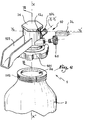
- the fire extinguisher 1 shown in FIG. 1 comprises a reservoir 2 of powder or additivated water provided with a bottom of range 3 allowing it to rest on a flat surface.
- the extinguisher is provided with a cap 4 which forms a handle 5 for handling the extinguisher.
- a flexible tube 6 extends from a rear region 4a of the cap 4 to a front region 4b of the same cap which is received in a discharge head 7 to be grasped by hand by a user .
- the head 7 is provided with a screen 7 a for protecting the hand of a user and with a lever 7 b for operating a relief valve not shown.
- a ring 8 makes it possible to operate a pin whose operation is explained in the following.
- a tap 10 is provided to be mounted on the orifice 2 a of the reservoir 2 and comprises a body 12 intended to be screwed into the orifice 2 a , thanks to an external thread 12 a , by being connected to a dip tube 14 whose open lower end, not shown, is disposed within the fire treatment fluid.
- a valve 16 is movable inside a bore 18 formed in the body 12. The axis of symmetry of the bore 18 is denoted XX ′.
- the bore 18 defines a seat 20 with a conical bearing intended to cooperate with the valve 16 in the closed position of the valve 10, as shown in Figures 3 and 4.
- the valve 16 comprises a head 22 of diameter less than the main part 24 of the valve 16, so that it defines a shoulder 26 for receiving an O-ring 28, this seal being intended to come into abutment against the seat 20 in the position of FIGS. 2 to 4.
- a bore 30 is provided in the body 12 in a direction Y 1 -Y 1 ′ generally perpendicular to the axis XX ′ and receives a connector 32 for connecting the flexible tube 6.
- valve 16 closes the bore 18 at the seat 20 and the bore 30 at its connection zone with the bore 18.
- the valve 16 is held in its position in FIGS. 2 to 4 by a pin 34 secured to the ring 8 visible in Figure 1.
- This pin which can be made of metal or plastic such as polyamide, is intended to pass right through the bore 18 according to a direction Y 2 -Y 2 'and also perpendicular to the axis X-X'.
- the body 12 is equipped with a plug 36, while the socket 12 b of the body 12 in which the bore 18 is formed is provided with two notches 12 c and 12 d which are not completely closed when the plug 36 is screwed in the upper part of the socket 12 b . It is thus possible to insert the pin 34 in the direction of the arrow F in FIG. 3. In this position, the pin 36 blocks the valve 16 in a position for closing the valve.
- the face 38 of the valve 16 opposite the tank 2 is equipped with a pin 40 at the level of its central part, that is to say at the level of the axis XX '.
- the pin 34 is equipped with a housing 42 for receiving the end of the pin 40.
- the pin 34 has a bevelled face 44 which facilitates its introduction, in the direction of arrow F, because its end front is fine, while its extraction in the opposite direction arrow F is also facilitated because the effect exerted by the valve 16 tends to drive out the pin.
- the plug 36 carries, on its internal face directed towards the bore 18, a housing 46 for receiving the pin 40 in open position of the tap, as shown in the figure 5.
- the face 38 of valve 16 may not bear a pin of the type of pin 40, the pin then being held in place only thanks to the pressure exerted by the valve.
- the bore 18 forms an internal shoulder 48 while the valve 16 has, at its rear face 38, a base 50 of diameter greater than its main part 24, such so that an external shoulder 52 is created on the valve 16.
- a spring 54 is arranged, between the shoulders 48 and 52, inside bore 18, around the main part 24 of the valve 16. This spring resiliently loads the valve 16 in a direction away from the seat 20, that is to say in a direction away from the reservoir 2, which corresponds to the opening of tap 10.
- Ring 8 and pin 34 can be secured after mounting the valve 10 on the tank 2 and putting in place of the cap 4.
- a pressure indicator 60 is mounted on a nozzle 62 of the body 12 in communication with the interior volume of the tank 2 in order to constantly know the pressure prevailing inside this tank.
- a fitting 64 provided a valve 66 makes it possible to feed, through a filter 68, the internal volume of the reservoir 2 in pressurization fluid.
- valve 10 it is possible to climb the valve 10 on the tank 2 while the pin 34 is in place in bore 18 and that valve 16 is held in the closed position.
- valve 66 which can be controlled thanks to the pressure indicator 60.
- the installation of a seal, the breaking of which can detect a displacement of the pin 34 can be carried out before fitting the cap 4, such a seal then being protected by the cap.
- the invention has been presented with a tap 10 protected by a cap and connected to a flexible tube. It is however applicable independently of such a cap 4 and, in particular, in the case of a tap connected directly to a projection nozzle connected directly to its outlet orifice, as shown in FIGS. 6 and 7, where the elements similar to those of the embodiment of FIGS. 1 to 5 bear identical references.
- a ring 101 makes it possible to screw the tap 10 onto an external thread 102 of the orifice 2 a of the reservoir 2.
- the body 12 of the tap 10 is extended by a handle 103 on one side while it carries, on the opposite side, a nozzle 104 for spraying the product contained in the tank.
- the nozzle 104 is connected to the interior volume of the body 12 by a conduit 30 for the outlet of the fire treatment fluid.
- a valve 16 is housed in a bore 18 of the body 12 and operates as indicated with reference to the first embodiment, the valve being shown in the closed position of the valve 10 on the left of FIG. 7 and in the open position on the right of this figure.
- the recoil movement of the valve in the body 12 in a direction away from the reservoir is limited by a plug 36.
- a pin 34 can block this movement by insertion in the notches of the body 12, only one of which is visible with the reference 12 c .
- a pressure indicator 60 is connected to a nozzle 62 of the body 12.
- the valve 16 is equipped with two O-rings 128 a and 128 b intended to bear respectively against two parts 118 a and 118 b of the radial surface of the bore 18 which are of different diameters.
- the seals 128 a and 128 b thus constitute sealing segments between the valve 16 and the bore 18.
- a shoulder 48 provided, in the body 12, between the surfaces 118 a and 118 b cooperates with a corresponding shoulder 148 provided on the valve 16.
- No spring is provided to elastically load the valve 16 in the direction of the plug 36 because the pressure prevailing in tank 2 is sufficient to push the piston in valve opening position, as shown in the right of Figure 7, as soon as the pin 34 has been removed.
- the cover 36 carries a central pin 136 around which is immobilized, by cooperation of forms, a ring elastic 137 made of elastomer or equivalent which allows cushioning the impact of the valve 16 against the plug 36 during its passage from its closed position to its open position.
- the handle 103 can be removable relative to the body 12.
- the body 12 may be made of metal, in particular brass, or of material plastic while the valve can also be made of metal or made of plastic, especially of polyamide filled with fibers reinforcement.
- the invention was shown with a dip tube 14, it is however applicable in the absence of such a dip tube, in particular when the extinguisher is intended to be used "head on low".
Applications Claiming Priority (2)
| Application Number | Priority Date | Filing Date | Title |
|---|---|---|---|
| FR9814371A FR2785817B1 (fr) | 1998-11-12 | 1998-11-12 | Robinet et extincteur portable a pression permanente equipe d'un tel robinet |
| FR9814371 | 1998-11-12 |
Publications (1)
| Publication Number | Publication Date |
|---|---|
| EP1000635A1 true EP1000635A1 (de) | 2000-05-17 |
Family
ID=9532776
Family Applications (1)
| Application Number | Title | Priority Date | Filing Date |
|---|---|---|---|
| EP99420226A Withdrawn EP1000635A1 (de) | 1998-11-12 | 1999-11-10 | Ventil und mit einem solchen Ventil ausgerüsteter tragbarer Dauerdruckfeuerlöscher |
Country Status (2)
| Country | Link |
|---|---|
| EP (1) | EP1000635A1 (de) |
| FR (1) | FR2785817B1 (de) |
Cited By (5)
| Publication number | Priority date | Publication date | Assignee | Title |
|---|---|---|---|---|
| EP1302710A3 (de) * | 2001-10-09 | 2003-08-13 | L.P.G. Tecnicas en Extincion de Incendios, S.A. | Ventil für einen Behälter mit Hochdrucklöschmittel |
| EP1510235A1 (de) * | 2003-08-27 | 2005-03-02 | KIDDE-DEUGRA Brandschutzsysteme GmbH | Feuerlöscheinrichtung |
| CN101695595B (zh) * | 2009-10-14 | 2011-07-27 | 攀钢集团冶金工程技术有限公司 | 气瓶放气结构、放气工具及气瓶嘴 |
| CN102145217A (zh) * | 2010-02-10 | 2011-08-10 | 庄诸葛 | 一种ig541气体灭火系统的容器阀多功能组合接口单元 |
| CN102614609A (zh) * | 2012-04-16 | 2012-08-01 | 厦门一泰消防科技开发有限公司 | 一种灭火器阀门压把安全防护装置 |
Citations (6)
| Publication number | Priority date | Publication date | Assignee | Title |
|---|---|---|---|---|
| US3719231A (en) * | 1971-05-14 | 1973-03-06 | K Haggard | Attachment for automatic override of manually operated compressed gas fire extinguishers and alarms |
| DE2659113A1 (de) * | 1976-12-28 | 1978-07-06 | Hahn Metallbau Gmbh | Feuerloeschgeraet |
| FR2505970A1 (fr) * | 1981-05-15 | 1982-11-19 | Sicli | Tete a valve protegee pour extincteur a pression permanente |
| DE4225997A1 (de) | 1992-08-06 | 1994-02-10 | Total Feuerschutz Gmbh | Schnellöffnungsventil |
| FR2741811A1 (fr) | 1995-12-05 | 1997-06-06 | Snc S2E Services | Appareil extincteur et berceau pour la fixation de cet appareil, lorsqu'il est portable, a un support |
| EP0867204A1 (de) * | 1997-03-26 | 1998-09-30 | Gloria-Werke H. Schulte-Frankenfeld GmbH & Co. | Vorrichtung zur Aktivierung eines Feuerlöschers |
-
1998
- 1998-11-12 FR FR9814371A patent/FR2785817B1/fr not_active Expired - Fee Related
-
1999
- 1999-11-10 EP EP99420226A patent/EP1000635A1/de not_active Withdrawn
Patent Citations (6)
| Publication number | Priority date | Publication date | Assignee | Title |
|---|---|---|---|---|
| US3719231A (en) * | 1971-05-14 | 1973-03-06 | K Haggard | Attachment for automatic override of manually operated compressed gas fire extinguishers and alarms |
| DE2659113A1 (de) * | 1976-12-28 | 1978-07-06 | Hahn Metallbau Gmbh | Feuerloeschgeraet |
| FR2505970A1 (fr) * | 1981-05-15 | 1982-11-19 | Sicli | Tete a valve protegee pour extincteur a pression permanente |
| DE4225997A1 (de) | 1992-08-06 | 1994-02-10 | Total Feuerschutz Gmbh | Schnellöffnungsventil |
| FR2741811A1 (fr) | 1995-12-05 | 1997-06-06 | Snc S2E Services | Appareil extincteur et berceau pour la fixation de cet appareil, lorsqu'il est portable, a un support |
| EP0867204A1 (de) * | 1997-03-26 | 1998-09-30 | Gloria-Werke H. Schulte-Frankenfeld GmbH & Co. | Vorrichtung zur Aktivierung eines Feuerlöschers |
Cited By (8)
| Publication number | Priority date | Publication date | Assignee | Title |
|---|---|---|---|---|
| EP1302710A3 (de) * | 2001-10-09 | 2003-08-13 | L.P.G. Tecnicas en Extincion de Incendios, S.A. | Ventil für einen Behälter mit Hochdrucklöschmittel |
| ES2214926A1 (es) * | 2001-10-09 | 2004-09-16 | L.P.G. Tecnicas En Extincion De Incendios, S.A. | Valvula para recipientes contendores de agentes extintores a alta presion. |
| EP1510235A1 (de) * | 2003-08-27 | 2005-03-02 | KIDDE-DEUGRA Brandschutzsysteme GmbH | Feuerlöscheinrichtung |
| CN101695595B (zh) * | 2009-10-14 | 2011-07-27 | 攀钢集团冶金工程技术有限公司 | 气瓶放气结构、放气工具及气瓶嘴 |
| CN102145217A (zh) * | 2010-02-10 | 2011-08-10 | 庄诸葛 | 一种ig541气体灭火系统的容器阀多功能组合接口单元 |
| CN102145217B (zh) * | 2010-02-10 | 2012-10-03 | 庄诸葛 | 一种ig541气体灭火系统的容器阀多功能组合接口单元 |
| CN102614609A (zh) * | 2012-04-16 | 2012-08-01 | 厦门一泰消防科技开发有限公司 | 一种灭火器阀门压把安全防护装置 |
| CN102614609B (zh) * | 2012-04-16 | 2014-04-09 | 厦门一泰消防科技开发有限公司 | 一种灭火器阀门压把安全防护装置 |
Also Published As
| Publication number | Publication date |
|---|---|
| FR2785817B1 (fr) | 2001-01-26 |
| FR2785817A1 (fr) | 2000-05-19 |
Similar Documents
| Publication | Publication Date | Title |
|---|---|---|
| EP1943458B1 (de) | Vorrichtung zur steuerung einer fluidfüllung oder -extraktion und tank mit einer solchen vorrichtung | |
| EP1346946B1 (de) | Zapfpistole mit einer sicheren Arbeitsweise und Betankungsanlage mit einer derartigen Zapfpistole | |
| WO2007048957A1 (fr) | Organe de controle du remplissage et/ou du soutirage d'un gaz sous pression, reservoir et circuit munis d'un tel organe | |
| EP2878872B1 (de) | Schnellanschluss zur lösbaren Verbindung von zwei Rohren | |
| EP2354002B1 (de) | Verfahren und Vorrichtung zum Leeren eines Tanks, Tank und mit einer solchen Vorrichtung ausgestattetes Luftfahrzeug | |
| EP0900966B1 (de) | Sicherheits-Abschaltgerät für Flüssigkeitshandhabungs-Anlage | |
| EP3693653A1 (de) | Liefervorrichtung für ein unter druck stehendes fluid, und speichereinheit für unter druck stehendes fluid, die eine solche vorrichtung umfasst | |
| EP0010465A2 (de) | Sich automatisch öffnendes Ventil, insbesondere für Feuerlöschanlagen | |
| EP3578871A1 (de) | Zuführungsvorrichtung für unter druck stehende fluide | |
| EP1000635A1 (de) | Ventil und mit einem solchen Ventil ausgerüsteter tragbarer Dauerdruckfeuerlöscher | |
| EP3519323B1 (de) | Vorrichtung zur bereitstellung eines unter druck stehenden materials | |
| FR2779194A1 (fr) | Dispositif a fluide compressible | |
| FR2686680A1 (fr) | Appareillage de securite pour le chargement de capacites en gaz sous haute pression. | |
| EP0274452B1 (de) | Vorrichtung zum Aufstechen von Druckgasflaschen | |
| LU87670A1 (fr) | Cartouche de securite pour gaz comprime ou liquefie | |
| FR2944378A1 (fr) | Dispositif de conditionnement pour le stockage et/ou entreposage d'un milieu liquide radioactif | |
| WO2009138628A1 (fr) | Dispositif receveur de gaz sous pression, ensemble distributeur-dispositif receveur, et système d'alimentation correspondant | |
| FR2466643A1 (fr) | Ensemble a obturateur de l'orifice d'aspiration d'une pompe et mecanisme de commande de cet obturateur | |
| FR2537689A1 (fr) | Vanne d'extincteur a pression de fluide permanente | |
| EP0607770A1 (de) | Doppelarmatur Anordnung | |
| EP0340111A2 (de) | Differential-Auslöseventil für Leitungen von Flüssigkeiten unter Druck | |
| EP0792665A1 (de) | Flüssigkeitszerstäubungsfeuerlöscher | |
| FR2767901A1 (fr) | Coupe-circuit de securite pour installation de manutention de fluide | |
| FR2483789A1 (fr) | Mecanisme de commande d'un extincteur | |
| FR2556571A1 (fr) | Fermeture a separation rapide pour systemes de sauvetage |
Legal Events
| Date | Code | Title | Description |
|---|---|---|---|
| PUAI | Public reference made under article 153(3) epc to a published international application that has entered the european phase |
Free format text: ORIGINAL CODE: 0009012 |
|
| AK | Designated contracting states |
Kind code of ref document: A1 Designated state(s): AT BE CH CY DE DK ES FI FR GB GR IE IT LI LU MC NL PT SE |
|
| AX | Request for extension of the european patent |
Free format text: AL;LT;LV;MK;RO;SI |
|
| 17P | Request for examination filed |
Effective date: 20000901 |
|
| AKX | Designation fees paid |
Free format text: AT BE CH CY DE DK ES FI FR GB GR IE IT LI LU MC NL PT SE |
|
| RAP1 | Party data changed (applicant data changed or rights of an application transferred) |
Owner name: USINES DESAUTEL |
|
| 17Q | First examination report despatched |
Effective date: 20080317 |
|
| STAA | Information on the status of an ep patent application or granted ep patent |
Free format text: STATUS: THE APPLICATION IS DEEMED TO BE WITHDRAWN |
|
| 18D | Application deemed to be withdrawn |
Effective date: 20080930 |