EP1000635A1 - Valve and portable permanently presurized fire extinguisher provided with such a valve - Google Patents
Valve and portable permanently presurized fire extinguisher provided with such a valve Download PDFInfo
- Publication number
- EP1000635A1 EP1000635A1 EP99420226A EP99420226A EP1000635A1 EP 1000635 A1 EP1000635 A1 EP 1000635A1 EP 99420226 A EP99420226 A EP 99420226A EP 99420226 A EP99420226 A EP 99420226A EP 1000635 A1 EP1000635 A1 EP 1000635A1
- Authority
- EP
- European Patent Office
- Prior art keywords
- valve
- bore
- tap
- pin
- tap according
- Prior art date
- Legal status (The legal status is an assumption and is not a legal conclusion. Google has not performed a legal analysis and makes no representation as to the accuracy of the status listed.)
- Withdrawn
Links
Images


Classifications
-
- A—HUMAN NECESSITIES
- A62—LIFE-SAVING; FIRE-FIGHTING
- A62C—FIRE-FIGHTING
- A62C13/00—Portable extinguishers which are permanently pressurised or pressurised immediately before use
- A62C13/62—Portable extinguishers which are permanently pressurised or pressurised immediately before use with a single permanently pressurised container
- A62C13/64—Portable extinguishers which are permanently pressurised or pressurised immediately before use with a single permanently pressurised container the extinguishing material being released by means of a valve
Definitions
- the invention relates to a tap for a portable fire extinguisher. with permanent pressure and a portable pressure fire extinguisher permanent fitted with such a tap.
- a tap is mounted on the outlet of a fire extinguisher tank at permanent pressure to control the discharge of the fire treatment fluid.
- This tap can be connected to a diffuser or flexible hose at the free end which is mounted a spray head allowing direct the product, this head possibly being equipped a controlled shutter mechanism.
- Document FR-A-2 741 811 discloses a fire extinguisher permanent pressure comprising a tap with a head spray.
- a trigger of this spray head is engaged with a lever provided to move a valve from the fire extinguisher valve against prevailing pressure in the tank, in order to port the volume inside the tank and a tap outlet.
- a small locking rod is used for do this but this rod is small and the most great care must be taken during assembly for it to be positioned correctly, and over the lifetime of the extinguisher so that it is not lost, for example when fire extinguisher maintenance operations.
- the known system provides for the operation of the valve by the head of spraying, which requires the relative positioning of the valve, its control lever and the spray head in the rest position. This may not be timely, especially ergonomically.
- user may not fire on the spray head in a direction allowing the operation of the valve control lever, which induces the trigger failure and failure to open the valve.
- the invention relates to a tap for portable fire extinguisher with permanent pressure, this tap comprising a body intended to be mounted on the orifice of a tank of fire treatment fluid and a movable valve in translation between an open position and a valve closing position, while this valve is intended to pass from the closed position to the position opening of the tap by a translational movement in a sense of distance from the tank.
- This tap includes a removable valve locking member in valve closing position, this member being provided for oppose the movement of translation of the valve in the direction distance from the tank.
- the movement of the valve, during opening the tap does not require overcoming the pressure prevailing inside the tank but takes place in one direction compatible with this pressure, whatever its value.
- the valve can be constructed so that the valve disappears from the path of the fluid towards the outlet of the tap, that is to say is removed from this path and this, without use of a lever or complicated means of locking in open position.
- the removable locking member can be easily handled by a user and formed of a simple construction device, so that its cost is modest while fulfilling its function particularly reliable, without risk of jamming and / or necessity a power supply.
- the body includes a bore in which is housed, slidingly, the valve, a tap outlet conduit being provided into this body and opening into this bore.
- This bore effectively guides the valve over the entire length of its race. Means capable of elastic loading of the valve away from the tank can be planned.
- the bore advantageously forms an internal support shoulder for a compression spring, while the valve carries a corresponding external shoulder, the spring being disposed between these shoulders.
- the bore advantageously defines a seat of range of the valve, while the valve carries an O-ring suitable for come to rest against this seat.
- the valve is able to move from its closed valve position to its open position under the effect of the forces of pressure exerted by the fluid contained in the reservoir, without the action of a mechanical means such as a spring, the valve being provided with at least one seal with the surface radial of a bore in the body in which the valve.
- the organ advantageously is a removable pin intended to be received in the valve body in a position generally perpendicular to the direction of moving the valve.
- the side of the valve opposite the tank can carry a pawn capable of entering a corresponding housing of this pin. This pawn contributes to blocking in position of the pin in relation to the valve.
- the bottom of the bore includes a housing for receiving this pin in the open position of the valve.
- the bottom of the bore carries a means of damping the impact of the valve against this background.
- the invention also relates to a portable fire extinguisher with permanent pressure which includes a tap as above described.
- a fire extinguisher is particularly simple of use since it suffices to release the valve so that this no longer prevents the passage of the treatment fluid without taking special precautions to lock the valve in the open position.
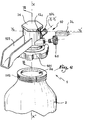
- the fire extinguisher 1 shown in FIG. 1 comprises a reservoir 2 of powder or additivated water provided with a bottom of range 3 allowing it to rest on a flat surface.
- the extinguisher is provided with a cap 4 which forms a handle 5 for handling the extinguisher.
- a flexible tube 6 extends from a rear region 4a of the cap 4 to a front region 4b of the same cap which is received in a discharge head 7 to be grasped by hand by a user .
- the head 7 is provided with a screen 7 a for protecting the hand of a user and with a lever 7 b for operating a relief valve not shown.
- a ring 8 makes it possible to operate a pin whose operation is explained in the following.
- a tap 10 is provided to be mounted on the orifice 2 a of the reservoir 2 and comprises a body 12 intended to be screwed into the orifice 2 a , thanks to an external thread 12 a , by being connected to a dip tube 14 whose open lower end, not shown, is disposed within the fire treatment fluid.
- a valve 16 is movable inside a bore 18 formed in the body 12. The axis of symmetry of the bore 18 is denoted XX ′.
- the bore 18 defines a seat 20 with a conical bearing intended to cooperate with the valve 16 in the closed position of the valve 10, as shown in Figures 3 and 4.
- the valve 16 comprises a head 22 of diameter less than the main part 24 of the valve 16, so that it defines a shoulder 26 for receiving an O-ring 28, this seal being intended to come into abutment against the seat 20 in the position of FIGS. 2 to 4.
- a bore 30 is provided in the body 12 in a direction Y 1 -Y 1 ′ generally perpendicular to the axis XX ′ and receives a connector 32 for connecting the flexible tube 6.
- valve 16 closes the bore 18 at the seat 20 and the bore 30 at its connection zone with the bore 18.
- the valve 16 is held in its position in FIGS. 2 to 4 by a pin 34 secured to the ring 8 visible in Figure 1.
- This pin which can be made of metal or plastic such as polyamide, is intended to pass right through the bore 18 according to a direction Y 2 -Y 2 'and also perpendicular to the axis X-X'.
- the body 12 is equipped with a plug 36, while the socket 12 b of the body 12 in which the bore 18 is formed is provided with two notches 12 c and 12 d which are not completely closed when the plug 36 is screwed in the upper part of the socket 12 b . It is thus possible to insert the pin 34 in the direction of the arrow F in FIG. 3. In this position, the pin 36 blocks the valve 16 in a position for closing the valve.
- the face 38 of the valve 16 opposite the tank 2 is equipped with a pin 40 at the level of its central part, that is to say at the level of the axis XX '.
- the pin 34 is equipped with a housing 42 for receiving the end of the pin 40.
- the pin 34 has a bevelled face 44 which facilitates its introduction, in the direction of arrow F, because its end front is fine, while its extraction in the opposite direction arrow F is also facilitated because the effect exerted by the valve 16 tends to drive out the pin.
- the plug 36 carries, on its internal face directed towards the bore 18, a housing 46 for receiving the pin 40 in open position of the tap, as shown in the figure 5.
- the face 38 of valve 16 may not bear a pin of the type of pin 40, the pin then being held in place only thanks to the pressure exerted by the valve.
- the bore 18 forms an internal shoulder 48 while the valve 16 has, at its rear face 38, a base 50 of diameter greater than its main part 24, such so that an external shoulder 52 is created on the valve 16.
- a spring 54 is arranged, between the shoulders 48 and 52, inside bore 18, around the main part 24 of the valve 16. This spring resiliently loads the valve 16 in a direction away from the seat 20, that is to say in a direction away from the reservoir 2, which corresponds to the opening of tap 10.
- Ring 8 and pin 34 can be secured after mounting the valve 10 on the tank 2 and putting in place of the cap 4.
- a pressure indicator 60 is mounted on a nozzle 62 of the body 12 in communication with the interior volume of the tank 2 in order to constantly know the pressure prevailing inside this tank.
- a fitting 64 provided a valve 66 makes it possible to feed, through a filter 68, the internal volume of the reservoir 2 in pressurization fluid.
- valve 10 it is possible to climb the valve 10 on the tank 2 while the pin 34 is in place in bore 18 and that valve 16 is held in the closed position.
- valve 66 which can be controlled thanks to the pressure indicator 60.
- the installation of a seal, the breaking of which can detect a displacement of the pin 34 can be carried out before fitting the cap 4, such a seal then being protected by the cap.
- the invention has been presented with a tap 10 protected by a cap and connected to a flexible tube. It is however applicable independently of such a cap 4 and, in particular, in the case of a tap connected directly to a projection nozzle connected directly to its outlet orifice, as shown in FIGS. 6 and 7, where the elements similar to those of the embodiment of FIGS. 1 to 5 bear identical references.
- a ring 101 makes it possible to screw the tap 10 onto an external thread 102 of the orifice 2 a of the reservoir 2.
- the body 12 of the tap 10 is extended by a handle 103 on one side while it carries, on the opposite side, a nozzle 104 for spraying the product contained in the tank.
- the nozzle 104 is connected to the interior volume of the body 12 by a conduit 30 for the outlet of the fire treatment fluid.
- a valve 16 is housed in a bore 18 of the body 12 and operates as indicated with reference to the first embodiment, the valve being shown in the closed position of the valve 10 on the left of FIG. 7 and in the open position on the right of this figure.
- the recoil movement of the valve in the body 12 in a direction away from the reservoir is limited by a plug 36.
- a pin 34 can block this movement by insertion in the notches of the body 12, only one of which is visible with the reference 12 c .
- a pressure indicator 60 is connected to a nozzle 62 of the body 12.
- the valve 16 is equipped with two O-rings 128 a and 128 b intended to bear respectively against two parts 118 a and 118 b of the radial surface of the bore 18 which are of different diameters.
- the seals 128 a and 128 b thus constitute sealing segments between the valve 16 and the bore 18.
- a shoulder 48 provided, in the body 12, between the surfaces 118 a and 118 b cooperates with a corresponding shoulder 148 provided on the valve 16.
- No spring is provided to elastically load the valve 16 in the direction of the plug 36 because the pressure prevailing in tank 2 is sufficient to push the piston in valve opening position, as shown in the right of Figure 7, as soon as the pin 34 has been removed.
- the cover 36 carries a central pin 136 around which is immobilized, by cooperation of forms, a ring elastic 137 made of elastomer or equivalent which allows cushioning the impact of the valve 16 against the plug 36 during its passage from its closed position to its open position.
- the handle 103 can be removable relative to the body 12.
- the body 12 may be made of metal, in particular brass, or of material plastic while the valve can also be made of metal or made of plastic, especially of polyamide filled with fibers reinforcement.
- the invention was shown with a dip tube 14, it is however applicable in the absence of such a dip tube, in particular when the extinguisher is intended to be used "head on low".
Abstract
Description
L'invention a trait à un robinet pour extincteur portable à pression permanente et à un extincteur portable à pression permanente équipé d'un tel robinet.The invention relates to a tap for a portable fire extinguisher. with permanent pressure and a portable pressure fire extinguisher permanent fitted with such a tap.
Un robinet est monté sur le débouché d'un réservoir d'extincteur à pression permanente pour contrôler la décharge du fluide de traitement d'incendie. Ce robinet peut être relié à un diffuseur ou à un tuyau flexible à l'extrémité libre duquel est montée une tête de pulvérisation permettant de diriger le produit, cette tête étant éventuellement équipée d'un mécanisme d'obturation commandée.A tap is mounted on the outlet of a fire extinguisher tank at permanent pressure to control the discharge of the fire treatment fluid. This tap can be connected to a diffuser or flexible hose at the free end which is mounted a spray head allowing direct the product, this head possibly being equipped a controlled shutter mechanism.
Par le document FR-A-2 741 811, on connaít un extincteur à pression permanente comprenant un robinet pourvu d'une tête de pulvérisation. Une gâchette de cette tête de pulvérisation est en prise avec un levier prévu pour déplacer un clapet du robinet de l'extincteur contre la force de la pression régnant dans le réservoir, afin de mettre en communication le volume intérieur du réservoir et un orifice de sortie du robinet. Le tait que le clapet est déplacé à l'encontre de la pression régnant dans le réservoir rend cette manoeuvre relativement difficile dans la mesure où cette pression s'oppose au mouvement d'ouverture du clapet. En outre, un moyen de verrouillage du clapet en position ouverte doit être prévu, faute de quoi le clapet est refermé dès que l'utilisateur cesse d'exercer sur le levier un effort de déplacement du clapet, en particulier lorsqu'il se sert de l'extincteur pour éteindre un incendie. Une petite tige de verrouillage est utilisée pour ce faire, mais cette tige est de faibles dimensions et le plus grand soin doit être apporté lors du montage pour qu'elle soit positionnée correctement, et au cours de la durée de vie de l'extincteur pour qu'elle ne soit pas égarée, par exemple lors des opérations de maintenance de l'extincteur. En outre, le système connu prévoit la manoeuvre du clapet par la tête de pulvérisation, ce qui impose le positionnement relatif du clapet, de son levier de commande et de la tête de pulvérisation dans la position de repos. Ceci peut ne pas être opportun, notamment sur le plan ergonomique. Enfin, lors d'une manoeuvre rapide de la tête de pulvérisation, notamment en cas de panique devant un incendie, l'utilisateur peut ne pas tirer sur la tête de pulvérisation dans un sens permettant la manoeuvre du levier de commande du clapet, ce qui induit la rupture de la gâchette et la non-ouverture du robinet.Document FR-A-2 741 811 discloses a fire extinguisher permanent pressure comprising a tap with a head spray. A trigger of this spray head is engaged with a lever provided to move a valve from the fire extinguisher valve against prevailing pressure in the tank, in order to port the volume inside the tank and a tap outlet. The was that the valve was moved against the pressure reigning in the tank makes this maneuver relatively difficult since this pressure is opposed to the movement opening the valve. In addition, a locking means the valve in the open position must be provided, otherwise the valve is closed as soon as the user stops exercising on the lever an effort to move the valve, in particular when using the extinguisher to extinguish a fire. A small locking rod is used for do this but this rod is small and the most great care must be taken during assembly for it to be positioned correctly, and over the lifetime of the extinguisher so that it is not lost, for example when fire extinguisher maintenance operations. In addition, the known system provides for the operation of the valve by the head of spraying, which requires the relative positioning of the valve, its control lever and the spray head in the rest position. This may not be timely, especially ergonomically. Finally, during a rapid operation of the spray head, especially in the event of panic in the face of fire, user may not fire on the spray head in a direction allowing the operation of the valve control lever, which induces the trigger failure and failure to open the valve.
Par ailleurs, il est connu de DE-A-42 25 997 de réaliser une vanne à ouverture rapide au moyen d'une cartouche pyrotechnique apte à agir sur un piston, de telle sorte que sont libérées des billes d'ancrage d'un élément cylindrique dans un manchon fixe, l'élément cylindrique étant alors libéré pour permettre un mouvement de retrait d'un clapet monté en partie supérieure d'un réservoir. Un tel système est particulièrement complexe sur le plan mécanique et peut présenter des défauts de fiabilité, notamment en cas de grippage des billes qui peuvent demeurer dans leur logement pendant plusieurs années. En outre, la charge pyrotechnique doit être alimentée en courant pour déclencher l'étincelle nécessaire à l'expansion du gaz, ce qui requiert l'utilisation d'une ligne d'alimentation électrique à partir d'une source de tension, une telle construction n'étant pas adaptée à un extincteur portable. Dans tous les cas, un tel système est particulièrement onéreux et doit être réservé à des installations élaborées.Furthermore, it is known from DE-A-42 25 997 to carry out a quick-opening valve by means of a cartridge pyrotechnic capable of acting on a piston, so that are released from the anchor balls of a cylindrical element in a fixed sleeve, the cylindrical element then being released to allow a withdrawal movement of a valve mounted in upper part of a tank. Such a system is particularly mechanically complex and may have reliability defects, especially in the event of seizure of the balls who can stay in their accommodation for several years. In addition, the pyrotechnic charge must be supplied running to trigger the spark needed for expansion gas, which requires the use of a line power supply from a voltage source, such a construction not being suitable for a fire extinguisher portable. In any case, such a system is particularly expensive and must be reserved for installations developed.
C'est à ces inconvénients qu'entend plus particulièrement remédier l'invention, en proposant un robinet dont l'ouverture est facilitée par rapport aux robinets de l'état de la technique et qui ne nécessite ni l'utilisation d'un levier de manoeuvre d'un clapet, ni l'utilisation d'un organe de verrouillage d'un tel levier en position ouverte du robinet, ni le recours à un système électro-mécanique complexe avec charge pyrotechnique.It is to these disadvantages that we hear more particularly remedy the invention, by proposing a tap whose opening is facilitated compared to the taps of the state of the technical and which does not require the use of a operation of a valve, or the use of a locking of such a lever in the open position of the valve, nor the use of a complex electro-mechanical system with pyrotechnic charge.
Dans cet esprit, l'invention concerne un robinet pour extincteur portable à pression permanente, ce robinet comprenant un corps prévu pour être monté sur l'orifice d'un réservoir de fluide de traitement d'incendie et un clapet mobile en translation entre une position de d'ouverture et une position de fermeture du robinet, alors que ce clapet est prévu pour passer de la position de fermeture à la position d'ouverture du robinet par un mouvement de translation dans un sens d'éloignement par rapport au réservoir. Ce robinet comprend un organe amovible de verrouillage du clapet en position de fermeture du robinet, cet organe étant prévu pour s'opposer au mouvement de translation du clapet dans le sens d'éloignement par rapport au réservoir.In this spirit, the invention relates to a tap for portable fire extinguisher with permanent pressure, this tap comprising a body intended to be mounted on the orifice of a tank of fire treatment fluid and a movable valve in translation between an open position and a valve closing position, while this valve is intended to pass from the closed position to the position opening of the tap by a translational movement in a sense of distance from the tank. This tap includes a removable valve locking member in valve closing position, this member being provided for oppose the movement of translation of the valve in the direction distance from the tank.
Grâce à l'invention, le mouvement du clapet, lors de l'ouverture du robinet ne nécessite pas de vaincre la pression régnant à l'intérieur du réservoir, mais a lieu dans un sens compatible avec cette pression, quelle que soit sa valeur. Le robinet peut être construit de telle sorte que le clapet s'efface du trajet du fluide vers l'orifice de sortie du robinet, c'est-à-dire est écarté de ce trajet et ce, sans utilisation d'un levier ou de moyens compliqués de blocage en position ouverte. L'organe amovible de verrouillage peut être aisément manipulé par un utilisateur et être formé d'un dispositif de construction simple, de telle sorte que son coût est modique alors qu'il remplit sa fonction de façon particulièrement fiable, sans risque de coincement et/ou nécessité d'une alimentation électrique.Thanks to the invention, the movement of the valve, during opening the tap does not require overcoming the pressure prevailing inside the tank but takes place in one direction compatible with this pressure, whatever its value. The valve can be constructed so that the valve disappears from the path of the fluid towards the outlet of the tap, that is to say is removed from this path and this, without use of a lever or complicated means of locking in open position. The removable locking member can be easily handled by a user and formed of a simple construction device, so that its cost is modest while fulfilling its function particularly reliable, without risk of jamming and / or necessity a power supply.
Selon un premier aspect avantageux de l'invention, le corps comprend un alésage dans lequel est logé, à coulissement, le clapet, un conduit de sortie du robinet étant ménagé dans ce corps et débouchant dans cet alésage. Cet alésage guide efficacement le clapet sur toute la longueur de sa course. Des moyens aptes à charger élastiquement le clapet dans un sens d'éloignement par rapport au réservoir peuvent être prévus. En particulier, l'alésage forme avantageusement un épaulement interne d'appui d'un ressort de compression, alors que le clapet porte un épaulement externe correspondant, le ressort étant disposé entre ces épaulements. D'autre part, l'alésage définit avantageusement un siège de portée du clapet, alors que le clapet porte un joint torique apte à venir en appui contre ce siège.According to a first advantageous aspect of the invention, the body includes a bore in which is housed, slidingly, the valve, a tap outlet conduit being provided into this body and opening into this bore. This bore effectively guides the valve over the entire length of its race. Means capable of elastic loading of the valve away from the tank can be planned. In particular, the bore advantageously forms an internal support shoulder for a compression spring, while the valve carries a corresponding external shoulder, the spring being disposed between these shoulders. On the other hand, the bore advantageously defines a seat of range of the valve, while the valve carries an O-ring suitable for come to rest against this seat.
Selon un mode de réalisation de l'invention, le clapet est apte à passer de sa position de fermeture du robinet à sa position d'ouverture sous l'effet des seules forces de pression exercées par le fluide contenu dans le réservoir, sans action d'un moyen mécanique tel qu'un ressort, le clapet étant pourvu d'au moins un joint d'étanchéité avec la surface radiale d'un alésage du corps dans lequel peut coulisser le clapet.According to one embodiment of the invention, the valve is able to move from its closed valve position to its open position under the effect of the forces of pressure exerted by the fluid contained in the reservoir, without the action of a mechanical means such as a spring, the valve being provided with at least one seal with the surface radial of a bore in the body in which the valve.
Selon un autre aspect avantageux de l'invention, l'organe de verrouillage est avantageusement une goupille extractible prévue pour être reçue dans le corps du robinet dans une position globalement perpendiculaire à la direction de déplacement du clapet. La face du clapet opposée au réservoir peut porter un pion apte à pénétrer dans un logement correspondant de cette goupille. Ce pion contribue au blocage en position de la goupille par rapport au robinet. On peut également prévoir que le fond de l'alésage comprend un logement de réception de ce pion en position d'ouverture du clapet.According to another advantageous aspect of the invention, the organ advantageously is a removable pin intended to be received in the valve body in a position generally perpendicular to the direction of moving the valve. The side of the valve opposite the tank can carry a pawn capable of entering a corresponding housing of this pin. This pawn contributes to blocking in position of the pin in relation to the valve. We can also provide that the bottom of the bore includes a housing for receiving this pin in the open position of the valve.
En variante, on peut prévoir que le fond de l'alésage porte un moyen d'amortissement de l'impact du clapet contre ce fond.Alternatively, it can be provided that the bottom of the bore carries a means of damping the impact of the valve against this background.
L'invention concerne également un extincteur portable à pression permanente qui comprend un robinet tel que précédemment décrit. Un tel extincteur est particulièrement simple d'utilisation puisqu'il suffit de libérer le clapet pour que celui-ci ne s'oppose plus au passage du fluide de traitement d'incendie sans prendre des précautions particulières pour bloquer le clapet en position d'ouverture.The invention also relates to a portable fire extinguisher with permanent pressure which includes a tap as above described. Such a fire extinguisher is particularly simple of use since it suffices to release the valve so that this no longer prevents the passage of the treatment fluid without taking special precautions to lock the valve in the open position.
L'invention sera mieux comprise et d'autres avantages de celle-ci apparaítront plus clairement à la lumière de la description qui va suivre de deux modes de réalisation d'un extincteur conforme à son principe donnée uniquement à titre d'exemple et faite en référence aux dessins annexés dans lesquels :
- la figure 1 est une vue en perspective d'un extincteur conforme à l'invention ;
- la figure 2 est une vue en perspective avec arrachement partiel d'un robinet monté sur l'extincteur de la figure 1 ;
- la figure 3 est une coupe longitudinale selon la ligne III-III à la figure 2 ;
- la figure 4 est une coupe longitudinale selon la ligne IV-IV à la figure 3 ;
- la figure 5 est une vue analogue à la figure 4 alors que le robinet est en position ouverte ;
- la figure 6 est une vue en perspective d'un robinet conforme à un second mode de réalisation de l'invention et de la partie supérieure d'un réservoir d'extincteur et
- la figure 7 est une coupe selon la ligne VII-VII à la figure 6.
- Figure 1 is a perspective view of a fire extinguisher according to the invention;
- Figure 2 is a perspective view with partial cutaway of a valve mounted on the fire extinguisher of Figure 1;
- Figure 3 is a longitudinal section along the line III-III in Figure 2;
- Figure 4 is a longitudinal section along the line IV-IV in Figure 3;
- Figure 5 is a view similar to Figure 4 while the valve is in the open position;
- FIG. 6 is a perspective view of a tap according to a second embodiment of the invention and of the upper part of a fire extinguisher tank, and
- FIG. 7 is a section along line VII-VII in FIG. 6.
L'extincteur 1 représenté à la figure 1 comprend un
réservoir 2 de poudre ou d'eau additivée muni d'un fond de
portée 3 permettant son appui sur une surface plane. Dans sa
partie supérieure, l'extincteur est muni d'une coiffe 4 qui
forme une poignée 5 de prise en main de l'extincteur. Un tube
flexible 6 s'étend à partir d'une zone arrière 4a de la coiffe
4 jusqu'à une zone avant 4b de cette même coiffe dans laquelle
est reçue une tête de décharge 7 destinée à être prise en main
par un utilisateur. La tête 7 est pourvue d'un écran 7a de
protection de la main d'un utilisateur et d'un levier 7b de
manoeuvre d'une vanne de décharge non représentée. Un anneau
8 permet de manoeuvrer une goupille dont le fonctionnement est
expliqué dans ce qui suit.The
Comme il ressort plus clairement de la figure 2, un
robinet 10 est prévu pour être monté sur l'orifice 2a du
réservoir 2 et comprend un corps 12 destiné à être vissé dans
l'orifice 2a, grâce à un filet externe 12a, en étant raccordé
à un tube plongeur 14 dont une extrémité inférieure ouverte,
non représentée, est disposée au sein du fluide de traitement
d'un incendie. Un clapet 16 est mobile à l'intérieur d'un
alésage 18 formé dans le corps 12. On note X-X' l'axe de
symétrie de l'alésage 18. L'alésage 18 définit un siège 20 à
portée conique destiné à coopérer avec le clapet 16 en
position fermée du robinet 10, comme représenté aux figures
3 et 4. Le clapet 16 comprend une tête 22 de diamètre
inférieur à la partie principale 24 du clapet 16, de telle
sorte qu'il définit un épaulement 26 de réception d'un joint
torique 28, ce joint étant prévu pour venir en appui contre
le siège 20 dans la position des figures 2 à 4.As can be seen more clearly from FIG. 2, a
Un perçage 30 est prévu dans le corps 12 selon une
direction Y1-Y1' globalement perpendiculaire à l'axe X-X' et
reçoit un raccord 32 de connexion du tube flexible 6.A
Dans la position des figures 2 à 4, le clapet 16 obture
l'alésage 18 au niveau du siège 20 et le perçage 30 au niveau
de sa zone de raccordement à l'alésage 18. Le clapet 16 est
maintenu dans sa position des figures 2 à 4 par une goupille
34 solidaire de l'anneau 8 visible à la figure 1. Cette
goupille, qui peut être réalisée en métal ou en matière
plastique telle qu'en polyamide, est prévue pour traverser de
part en part l'alésage 18 selon une direction Y2-Y2' et
également perpendiculaire à l'axe X-X'.In the position of FIGS. 2 to 4, the
Le corps 12 est équipé d'un bouchon 36, alors que la
douille 12b du corps 12 dans laquelle est ménagé l'alésage 18
est pourvue de deux encoches 12c et 12d qui ne sont pas
complètement obturées lorsque le bouchon 36 est vissé en
partie supérieure de la douille 12b. Il est ainsi possible
d'insérer la goupille 34 dans le sens de la flèche F à la
figure 3. Dans cette position, la goupille 36 bloque le clapet
16 dans une position de fermeture du robinet.The
Afin de positionner, avec une précision acceptable, la
goupille 34 par rapport au clapet et au corps 12, la face 38
du clapet 16 opposée au réservoir 2 est équipée d'un pion 40
au niveau de sa partie centrale, c'est-à-dire au niveau de
l'axe X-X'. Par ailleurs, la goupille 34 est équipée d'un
logement 42 de réception de l'extrémité du pion 40. Ainsi, la
coopération des éléments 40 et 42 résulte dans la création
d'un point dur lors de l'introduction de la goupille 34 dans
l'alésage 18, ce qui permet à un opérateur de détecter le bon
positionnement de la goupille par rapport au clapet. Ce point
dur diminue également les risques de déplacement intempestif
de la goupille lorsque celle-ci est en place, c'est-à-dire de
déverrouillage inopiné du robinet 10. Par ailleurs, la
goupille 34 possède une face en biseau 44 qui facilite son
introduction, dans le sens de la flèche F, car son extrémité
avant est fine, alors que son extraction dans le sens opposé
à la flèche F est également facilitée car l'effet exercé par
la clapet 16 tend à chasser la goupille.In order to position, with acceptable precision, the
Le bouchon 36 porte, sur sa face interne dirigée vers
l'alésage 18, un logement 46 de réception du pion 40 en
position ouverte du robinet, comme cela ressort de la figure
5.The
Selon une variante non représentée de l'invention, la
face 38 du clapet 16 peut ne pas porter de pion du type du
pion 40, la goupille étant alors maintenue en place uniquement
grâce à la pression exercée par le clapet.According to a variant not shown of the invention, the
L'alésage 18 forme un épaulement interne 48 alors que le
clapet 16 possède, au niveau de sa face arrière 38, une base
50 de diamètre supérieur à sa partie principale 24, de telle
sorte qu'il est créé un épaulement externe 52 sur le clapet
16. Un ressort 54 est disposé, entre les épaulements 48 et 52,
à l'intérieur de l'alésage 18, autour de la partie principale
24 du clapet 16. Ce ressort charge élastiquement le clapet 16
dans une direction d'éloignement du siège 20, c'est-à-dire
dans une direction d'éloignement par rapport au réservoir 2,
ce qui correspond à l'ouverture du robinet 10.The
Le fonctionnement est le suivant :The operation is as follows:
Lorsqu'il est nécessaire de se servir de l'extincteur 1,
l'utilisateur tire sur l'anneau 8 afin de le séparer de la
coiffe 4, de telle sorte que la goupille 34 est extraite de
l'alésage 18, par un déplacement dans le sens inverse de la
flèche F de la figure 3. L'effort combiné de la pression
s'exerçant sur la tête 22 et de la force de compression du
ressort 54 a pour effet de repousser le clapet 16 contre le
bouchon 36, libérant ainsi un passage entre le tube plongeur
14 et le perçage 30, ce passage permettant la circulation du
fluide de traitement d'incendie jusque vers la tête de
décharge 7. Le robinet est alors dans la position ouverte de
la figure 5.When it is necessary to use
Le déplacement du clapet 16 de sa position des figures
2 à 4 à sa position de la figure 5 est réalisé automatiquement
dès que la goupille 34 est retirée et sans intervention de
leviers et/ou d'organes de verrouillage. En d'autres termes,
l'ouverture du robinet 10 a lieu directement, dès le retrait
de la goupille 34.The displacement of the
En outre, la mise sous pression du tuyau flexible 6 qui résulte de l'ouverture du robinet 10 a lieu sans manipulation de la tête 7, de sorte que la séquence de mise en oeuvre de l'extincteur est particulièrement simple et logique pour un utilisateur, même paniqué :
- il dégoupille le robinet 10 ;
- il prend en main
la tête 7 pour la diriger vers les flammes et il contrôle le jet de fluide de traitement au moyen du levier 7b.
- he pins the
tap 10; - he takes the
head 7 in hand to direct it towards the flames and he controls the jet of treatment fluid by means of thelever 7 b .
L'anneau 8 et la goupille 34 peuvent être solidarisés
après le montage du robinet 10 sur le réservoir 2 et la mise
en place de la coiffe 4.
Un indicateur de pression 60 est monté sur un piquage 62
du corps 12 en communication avec le volume intérieur du
réservoir 2 afin de connaítre en permanence la pression
régnant à l'intérieur de ce réservoir. Un raccord 64 muni
d'une valve 66 permet d'alimenter, à travers un filtre 68, le
volume intérieur du réservoir 2 en fluide de pressurisation.A
Compte tenu de ce qui précède, il est possible de monter
le robinet 10 sur le réservoir 2 alors que la goupille 34 est
en place dans l'alésage 18 et que le clapet 16 est maintenu
en position fermée. On procède alors à la mise en pression du
réservoir 2, à travers la valve 66, ce qui peut être contrôlé
grâce à l'indicateur de pression 60. Il est ensuite possible
de monter la coiffe 4 autour du robinet 10 en partie supérieure
du réservoir 2 et de solidariser la goupille 34 et
l'anneau 8 par tout moyen approprié, alors que la coiffe 4
laisse apparaítre l'indicateur de pression 60, comme représenté
à la figure 1. La pose d'un scellé, dont la rupture
permet de détecter un déplacement de la goupille 34 peut être
effectué avant mise en place de la coiffe 4, un tel scellé
étant ensuite protégé par la coiffe.In view of the above, it is possible to climb
the
De la même manière, lors des intervention de maintenance
sur l'extincteur de l'invention, il est possible d'ouvrir la
coiffe 4 pour accéder au robinet 10, notamment à son raccord
de mise en pression 64.Similarly, during maintenance interventions
on the fire extinguisher of the invention, it is possible to open the
cover 4 to access the
L'invention a été présentée avec un robinet 10 protégé
par une coiffe et relié à un tube flexible. Elle est cependant
applicable indépendamment d'une telle coiffe 4 et, notamment,
dans le cas d'un robinet relié directement à une buse de
projection branchée directement sur son orifice de sortie,
comme représenté aux figures 6 et 7, où les éléments analogues
à ceux du mode de réalisation des figures 1 à 5 portent des
références identiques. Une bague 101 permet de visser le
robinet 10 sur un filet externe 102 de l'orifice 2a du réservoir
2. Le corps 12 du robinet 10 se prolonge par une poignée
103 sur un côté alors qu'il porte, sur le côté opposé, une
buse 104 de pulvérisation du produit contenu dans le réservoir.
La buse 104 est reliée au volume intérieur du corps 12
par un conduit 30 de sortie du fluide de traitement d'incendie.
Un clapet 16 est logé dans un alésage 18 du corps 12 et
fonctionne comme indiqué en référence au premier mode de
réalisation, le clapet étant représenté en position fermée du
robinet 10 sur la gauche de la figure 7 et en position ouverte
sur la droite de cette figure. Le mouvement de recul du clapet
dans le corps 12 dans un sens d'éloignement par rapport au
réservoir est limité par un bouchon 36. Une goupille 34 peut
bloquer ce mouvement par insertion dans des encoches du corps
12, dont une seule est visible avec la référence 12c. Un
indicateur de pression 60 est raccordé sur un piquage 62 du
corps 12.The invention has been presented with a
Le clapet 16 est équipé de deux joints toriques 128a et
128b destinés à venir en appui respectivement contre deux
parties 118a et 118b de la surface radiale de l'alésage 18 qui
sont de diamètres différents. Les joints 128a et 128b
constituent ainsi des segments d'étanchéité entre le clapet
16 et l'alésage 18. Un épaulement 48 prévu, dans le corps 12,
entre les surfaces 118a et 118b coopère avec un épaulement
correspondant 148 prévu sur le clapet 16.The
Aucun ressort n'est prévu pour charger élastiquement le
clapet 16 en direction du bouchon 36 car la pression régnant
dans le réservoir 2 est suffisante pour pousser le piston en
position d'ouverture du robinet, telle que représentée sur la
droite de la figure 7, dès que la goupille 34 a été retirée.No spring is provided to elastically load the
Le couvercle 36 porte un pion central 136 autour duquel
est immobilisée, par coopération de formes, une bague
élastique 137 en élastomère ou équivalent qui permet d'amortir
l'impact du clapet 16 contre le bouchon 36 lors de son passage
de sa position fermée à sa position ouverte.The
Selon une variante non représentée de ce second mode de
réalisation de l'invention, la poignée 103 peut être amovible
par rapport au corps 12.According to a variant not shown of this second mode of
embodiment of the invention, the
Quel que soit le mode de réalisation considéré, le corps
12 peut être en métal, notamment en laiton, ou en matière
plastique alors que le clapet peut également être en métal ou
en matière plastique, notamment en polyamide chargé de fibres
de renfort.Whatever the embodiment considered, the
Dans le premier mode de réalisation, l'invention a été
représentée avec un tube plongeur 14, elle est cependant
applicable en l'absence d'un tel tube plongeur, notamment
lorsque l'extincteur est prévu pour être utilisé "tête en
bas".In the first embodiment, the invention was
shown with a
Claims (11)
Applications Claiming Priority (2)
| Application Number | Priority Date | Filing Date | Title |
|---|---|---|---|
| FR9814371A FR2785817B1 (en) | 1998-11-12 | 1998-11-12 | PERMANENT PRESSURE PORTABLE TAP AND EXTINGUISHER EQUIPPED WITH SUCH A TAP |
| FR9814371 | 1998-11-12 |
Publications (1)
| Publication Number | Publication Date |
|---|---|
| EP1000635A1 true EP1000635A1 (en) | 2000-05-17 |
Family
ID=9532776
Family Applications (1)
| Application Number | Title | Priority Date | Filing Date |
|---|---|---|---|
| EP99420226A Withdrawn EP1000635A1 (en) | 1998-11-12 | 1999-11-10 | Valve and portable permanently presurized fire extinguisher provided with such a valve |
Country Status (2)
| Country | Link |
|---|---|
| EP (1) | EP1000635A1 (en) |
| FR (1) | FR2785817B1 (en) |
Cited By (5)
| Publication number | Priority date | Publication date | Assignee | Title |
|---|---|---|---|---|
| EP1302710A3 (en) * | 2001-10-09 | 2003-08-13 | L.P.G. Tecnicas en Extincion de Incendios, S.A. | Valve for recipient containers for high pressure extinguishing agents |
| EP1510235A1 (en) * | 2003-08-27 | 2005-03-02 | KIDDE-DEUGRA Brandschutzsysteme GmbH | Fire extinguishing system |
| CN101695595B (en) * | 2009-10-14 | 2011-07-27 | 攀钢集团冶金工程技术有限公司 | Air discharging structure of air bottle, air discharging tool and air bottle nozzle |
| CN102145217A (en) * | 2010-02-10 | 2011-08-10 | 庄诸葛 | Multi-functional combined interface unit of container valve of IG541 gas fire-extinguishing system |
| CN102614609A (en) * | 2012-04-16 | 2012-08-01 | 厦门一泰消防科技开发有限公司 | Safety device of fire extinguisher valve pressing handle |
Citations (6)
| Publication number | Priority date | Publication date | Assignee | Title |
|---|---|---|---|---|
| US3719231A (en) * | 1971-05-14 | 1973-03-06 | K Haggard | Attachment for automatic override of manually operated compressed gas fire extinguishers and alarms |
| DE2659113A1 (en) * | 1976-12-28 | 1978-07-06 | Hahn Metallbau Gmbh | Hand held fire extinguisher - has propellant gas cylinder and controls mounted separated by plastic seal from extinguishing agent |
| FR2505970A1 (en) * | 1981-05-15 | 1982-11-19 | Sicli | Fire extinguisher lever-operated valve - has tamper-proof enclosure for valve and sealed safety pin |
| DE4225997A1 (en) | 1992-08-06 | 1994-02-10 | Total Feuerschutz Gmbh | Quick opening valve |
| FR2741811A1 (en) | 1995-12-05 | 1997-06-06 | Snc S2E Services | EXTINGUISHING APPARATUS AND CRADLE FOR FIXING THIS APPARATUS, WHEN PORTABLE, TO A SUPPORT |
| EP0867204A1 (en) * | 1997-03-26 | 1998-09-30 | Gloria-Werke H. Schulte-Frankenfeld GmbH & Co. | Device for activating a fire extinguisher |
-
1998
- 1998-11-12 FR FR9814371A patent/FR2785817B1/en not_active Expired - Fee Related
-
1999
- 1999-11-10 EP EP99420226A patent/EP1000635A1/en not_active Withdrawn
Patent Citations (6)
| Publication number | Priority date | Publication date | Assignee | Title |
|---|---|---|---|---|
| US3719231A (en) * | 1971-05-14 | 1973-03-06 | K Haggard | Attachment for automatic override of manually operated compressed gas fire extinguishers and alarms |
| DE2659113A1 (en) * | 1976-12-28 | 1978-07-06 | Hahn Metallbau Gmbh | Hand held fire extinguisher - has propellant gas cylinder and controls mounted separated by plastic seal from extinguishing agent |
| FR2505970A1 (en) * | 1981-05-15 | 1982-11-19 | Sicli | Fire extinguisher lever-operated valve - has tamper-proof enclosure for valve and sealed safety pin |
| DE4225997A1 (en) | 1992-08-06 | 1994-02-10 | Total Feuerschutz Gmbh | Quick opening valve |
| FR2741811A1 (en) | 1995-12-05 | 1997-06-06 | Snc S2E Services | EXTINGUISHING APPARATUS AND CRADLE FOR FIXING THIS APPARATUS, WHEN PORTABLE, TO A SUPPORT |
| EP0867204A1 (en) * | 1997-03-26 | 1998-09-30 | Gloria-Werke H. Schulte-Frankenfeld GmbH & Co. | Device for activating a fire extinguisher |
Cited By (8)
| Publication number | Priority date | Publication date | Assignee | Title |
|---|---|---|---|---|
| EP1302710A3 (en) * | 2001-10-09 | 2003-08-13 | L.P.G. Tecnicas en Extincion de Incendios, S.A. | Valve for recipient containers for high pressure extinguishing agents |
| ES2214926A1 (en) * | 2001-10-09 | 2004-09-16 | L.P.G. Tecnicas En Extincion De Incendios, S.A. | Valve for recipient containers for high pressure extinguishing agents |
| EP1510235A1 (en) * | 2003-08-27 | 2005-03-02 | KIDDE-DEUGRA Brandschutzsysteme GmbH | Fire extinguishing system |
| CN101695595B (en) * | 2009-10-14 | 2011-07-27 | 攀钢集团冶金工程技术有限公司 | Air discharging structure of air bottle, air discharging tool and air bottle nozzle |
| CN102145217A (en) * | 2010-02-10 | 2011-08-10 | 庄诸葛 | Multi-functional combined interface unit of container valve of IG541 gas fire-extinguishing system |
| CN102145217B (en) * | 2010-02-10 | 2012-10-03 | 庄诸葛 | Multi-functional combined interface unit of container valve of IG541 gas fire-extinguishing system |
| CN102614609A (en) * | 2012-04-16 | 2012-08-01 | 厦门一泰消防科技开发有限公司 | Safety device of fire extinguisher valve pressing handle |
| CN102614609B (en) * | 2012-04-16 | 2014-04-09 | 厦门一泰消防科技开发有限公司 | Safety device of fire extinguisher valve pressing handle |
Also Published As
| Publication number | Publication date |
|---|---|
| FR2785817B1 (en) | 2001-01-26 |
| FR2785817A1 (en) | 2000-05-19 |
Similar Documents
| Publication | Publication Date | Title |
|---|---|---|
| EP1943458B1 (en) | Fluid filling and/or extraction control device and tank including one such device | |
| EP1346946B1 (en) | Secure operation filling nozzle and filling installation including such a filling nozzle | |
| WO2007048957A1 (en) | Element for controlling filling and/or drawing of a pressurized gas, tank and circuit provided with such an element | |
| EP2878872B1 (en) | Quick coupling for detachable connection of two pipes | |
| EP2354002B1 (en) | Method and device for emptying a tank, tank and aircraft provided with such a device | |
| EP0900966B1 (en) | Safety disconnection device for fluid handling plant | |
| EP2737234A1 (en) | Filling connector, container, filling method and filling nozzle | |
| EP3693653A1 (en) | Device for supplying fluid under pressure and assembly for storing pressurised fluid including such a device | |
| EP0010465A2 (en) | Automatic discharge valve, especially for fire extinguishing systems | |
| EP3578871A1 (en) | Device for delivering fluid under pressure | |
| EP1000635A1 (en) | Valve and portable permanently presurized fire extinguisher provided with such a valve | |
| EP3519323B1 (en) | Device for supplying a pressurised material | |
| FR2686680A1 (en) | Safety equipment for loading volumes with high pressure gas | |
| EP0274452B1 (en) | System for perforating compressed-gas cartridges | |
| LU87670A1 (en) | SAFETY CARTRIDGE FOR COMPRESSED OR LIQUEFIED GAS | |
| FR2944378A1 (en) | PACKAGING DEVICE FOR STORING AND / OR STORING A RADIOACTIVE LIQUID MEDIUM | |
| FR2466643A1 (en) | SHUTTER ASSEMBLY OF THE PUMP SUCTION PORT AND CONTROL MECHANISM OF THE SHUTTER | |
| FR2537689A1 (en) | Extinguisher valve with permanent fluid pressure. | |
| EP0607770A1 (en) | Double valve arrangement | |
| EP0340111A2 (en) | Triggered differential valve for a pressurized-fluid circuit | |
| FR2767901A1 (en) | Breakable connection in supply of fluid under pressure | |
| FR2808081A1 (en) | Safety device for preventing use of shotgun includes a stator engaged in the gun barrel, housing a lock mechanism actuated via a key | |
| FR2483789A1 (en) | Fire extinguisher control mechanism - has screw-threaded bush forming abutment for return spring acting against striker | |
| FR2556571A1 (en) | RAPID SEPARATION CLOSURE FOR LIFE-SAVING SYSTEMS | |
| EP1000636A1 (en) | Extinguisher with reservoir, discharge head and flexible conduit |
Legal Events
| Date | Code | Title | Description |
|---|---|---|---|
| PUAI | Public reference made under article 153(3) epc to a published international application that has entered the european phase |
Free format text: ORIGINAL CODE: 0009012 |
|
| AK | Designated contracting states |
Kind code of ref document: A1 Designated state(s): AT BE CH CY DE DK ES FI FR GB GR IE IT LI LU MC NL PT SE |
|
| AX | Request for extension of the european patent |
Free format text: AL;LT;LV;MK;RO;SI |
|
| 17P | Request for examination filed |
Effective date: 20000901 |
|
| AKX | Designation fees paid |
Free format text: AT BE CH CY DE DK ES FI FR GB GR IE IT LI LU MC NL PT SE |
|
| RAP1 | Party data changed (applicant data changed or rights of an application transferred) |
Owner name: USINES DESAUTEL |
|
| 17Q | First examination report despatched |
Effective date: 20080317 |
|
| STAA | Information on the status of an ep patent application or granted ep patent |
Free format text: STATUS: THE APPLICATION IS DEEMED TO BE WITHDRAWN |
|
| 18D | Application deemed to be withdrawn |
Effective date: 20080930 |