EP1000464B1 - Messverfahren und messeinrichtung zum messen der verzerrung eines hochfrequenz-leistungsverstärkers und entzerrungsverfahren und entzerrungseinrichtung - Google Patents
Messverfahren und messeinrichtung zum messen der verzerrung eines hochfrequenz-leistungsverstärkers und entzerrungsverfahren und entzerrungseinrichtung Download PDFInfo
- Publication number
- EP1000464B1 EP1000464B1 EP98943792A EP98943792A EP1000464B1 EP 1000464 B1 EP1000464 B1 EP 1000464B1 EP 98943792 A EP98943792 A EP 98943792A EP 98943792 A EP98943792 A EP 98943792A EP 1000464 B1 EP1000464 B1 EP 1000464B1
- Authority
- EP
- European Patent Office
- Prior art keywords
- phase
- power amplifier
- frequency power
- amplitude
- envelope
- Prior art date
- Legal status (The legal status is an assumption and is not a legal conclusion. Google has not performed a legal analysis and makes no representation as to the accuracy of the status listed.)
- Expired - Lifetime
Links
- 238000012937 correction Methods 0.000 title claims abstract description 45
- 238000000034 method Methods 0.000 title claims description 34
- 230000001360 synchronised effect Effects 0.000 claims abstract description 30
- 239000000969 carrier Substances 0.000 claims description 7
- 230000001419 dependent effect Effects 0.000 claims description 5
- 238000005259 measurement Methods 0.000 claims description 2
- 239000003607 modifier Substances 0.000 abstract 1
- 238000001228 spectrum Methods 0.000 description 17
- 230000006870 function Effects 0.000 description 12
- 238000010586 diagram Methods 0.000 description 5
- 230000005540 biological transmission Effects 0.000 description 4
- 238000004088 simulation Methods 0.000 description 4
- 230000010363 phase shift Effects 0.000 description 3
- 230000032683 aging Effects 0.000 description 2
- 238000011161 development Methods 0.000 description 2
- 230000018109 developmental process Effects 0.000 description 2
- 230000003321 amplification Effects 0.000 description 1
- 238000013459 approach Methods 0.000 description 1
- 238000010276 construction Methods 0.000 description 1
- 238000003199 nucleic acid amplification method Methods 0.000 description 1
- 238000012545 processing Methods 0.000 description 1
- 230000003014 reinforcing effect Effects 0.000 description 1
Images


Classifications
-
- H—ELECTRICITY
- H03—ELECTRONIC CIRCUITRY
- H03F—AMPLIFIERS
- H03F1/00—Details of amplifiers with only discharge tubes, only semiconductor devices or only unspecified devices as amplifying elements
- H03F1/32—Modifications of amplifiers to reduce non-linear distortion
- H03F1/3241—Modifications of amplifiers to reduce non-linear distortion using predistortion circuits
- H03F1/3276—Modifications of amplifiers to reduce non-linear distortion using predistortion circuits using the nonlinearity inherent to components, e.g. a diode
-
- H—ELECTRICITY
- H03—ELECTRONIC CIRCUITRY
- H03F—AMPLIFIERS
- H03F1/00—Details of amplifiers with only discharge tubes, only semiconductor devices or only unspecified devices as amplifying elements
- H03F1/32—Modifications of amplifiers to reduce non-linear distortion
- H03F1/3241—Modifications of amplifiers to reduce non-linear distortion using predistortion circuits
- H03F1/3247—Modifications of amplifiers to reduce non-linear distortion using predistortion circuits using feedback acting on predistortion circuits
-
- H—ELECTRICITY
- H03—ELECTRONIC CIRCUITRY
- H03F—AMPLIFIERS
- H03F1/00—Details of amplifiers with only discharge tubes, only semiconductor devices or only unspecified devices as amplifying elements
- H03F1/32—Modifications of amplifiers to reduce non-linear distortion
- H03F1/3241—Modifications of amplifiers to reduce non-linear distortion using predistortion circuits
- H03F1/3282—Acting on the phase and the amplitude of the input signal
Definitions
- the invention relates to a measuring method for measuring the distortion of a high-frequency power amplifier and a corresponding measuring device.
- the invention further relates to an equalization method for automatically equalizing a high frequency power amplifier and a corresponding equalization device.
- High-frequency power amplifiers usually have a not completely linear Characteristic on. There is therefore a distortion caused by the high-frequency power amplifier amplified high-frequency signal. Due to the nonlinearities of the High frequency power amplifier creates an undesirable interference spectrum.
- Multi-carrier signals such as those used in the digital transmission of audio and video signals Find use, the interference spectrum is expressed in outside the transmission band lying out of band interference and in lying within the transmission band Inbandspatien. To ensure proper transmission of the multi-carrier signal ensure, the interference spectrum must be a predetermined level distance from the Have useful signal.
- the linearity of the high frequency power amplifier in the Power amplifier for DAB (Digital Audio Broadcasting) signals and DVB (digital video broadcasting) signals are therefore subject to relatively high requirements.
- the Input a multi-carrier adjustment signal and the output signal of the High frequency power amplifiers with a spectrum analyzer.
- a Predistortion device which predistorts the gain to be amplified High frequency signal allowed.
- the predistortion characteristic is e.g. B. by a diode resistor network fixed with variable resistors so that the Curve of the pre-equalization characteristic variable through a variety of parameters is adjustable.
- the object is achieved with respect to the measuring method by the features of claim 1, with regard to the equalization process by the features of claim 8, with regard to the measuring device by the features of claim 16 and in terms of Equalization device solved by the features of claim 17.
- the measuring method according to the invention has the advantage that the modulation characteristic of the high-frequency power amplifier is displayed directly.
- the operator has therefore in the adjustment of the high-frequency power amplifier or one before High-frequency power amplifier arranged predistortion device an effective Alignment criterion, namely the greatest possible linearization of the To achieve the control characteristic.
- Claims 2 to 7 contain advantageous developments of the invention Measuring method.
- the output envelope and the input envelope are advantageously generated according to claims 2 and 3 by means of synchronous demodulation.
- to Display of the phase angle according to claims 4 and 5 is from the output envelope generates both an in-phase component and a quadrature component. From the ratio of these two components, the phase angle of the Determine output signal.
- the synchronous demodulation of the In-phase component and the quadrature component according to claim 6 in separate synchronous demodulators. It is also preferred according to claim 7 the reference carrier is subjected to a phase shift which the Corresponds to signal delay time by the high frequency amplifier.
- the advantage of the equalization method according to claim 8 is that in an adjustment mode by means of a suitable adjustment signal an amplitude correction factor obtained for the input signal of the high-frequency power amplifier and the input signal is subjected to automatic amplitude predistortion Consideration of the amplitude correction factor is subjected.
- the comparison of the Pre-distortion device takes place automatically, which increases the time required for the Commissioning significantly reduced.
- phase correction factor is also preferred obtained and the input signal under an automatic phase predistortion Subject to use of the phase correction factor.
- the amplitude correction factor and possibly the phase correction factor fed to a predistortion device whose modulation characteristic and possibly phase characteristic inverse to the modulation characteristic and phase characteristic of the High frequency amplifier can be set automatically.
- the input envelope and the output envelope digitized and for calculating the amplitude correction factor and possibly the phase correction factor fed to a control computer.
- a matching signal can be used in a particularly simple manner in accordance with claim 13 serve amplitude-modulated single carrier signal.
- Another particularly suitable one Alignment signal is a multi-carrier signal according to claim 14, in which all carriers are in the same phase state. This adjustment signal comes to the Useful signal relatively close, but has no phase fluctuations and is therefore for the Matching particularly suitable. Basically, however, this also comes as an adjustment signal Useful signal into consideration.
- the high-frequency power amplifier is made up of several parallel modules, structurally identical sub-amplifiers is composed, it is sufficient according to claim 15, only compare one of the sub-amplifiers with the equalization method according to the invention and the predistortion factors for the input signals of the other sub-amplifiers in to take over in the same way.
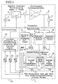
- Fig. 1 shows a block diagram of the measuring device according to the invention for measuring the Distortion of a high frequency power amplifier.
- Fig. 1 shows a block diagram of the measuring device according to the invention for measuring the Distortion of a high frequency power amplifier.
- a calibration signal generated by a signal source 1 is transmitted via a Predistortion device 2 the input of a high-frequency power amplifier 3 fed.
- a Load resistor 4 e.g. B. the feed resistance of a transmitting antenna.
- the power amplifier is not completely due to the construction linearized control characteristic and a phase characteristic.
- the control characteristic is in following the output power of the high frequency power amplifier as a function of it Understood input power.
- the control characteristic can also be used as Define the output amplitude as a function of the input amplitude.
- the output phase characteristic i. H. the initial phase of High frequency power amplifier understood as a function of its output power.
- the Phase characteristic can also be used as the output phase as a function of the output amplitude of the Define the function of the input power or input amplitude.
- Both the input signal 7 of the high-frequency power amplifier 3 and the output signal 6 of the high-frequency power amplifier are measured and fed to the measuring device 5 according to the invention.
- the input envelope U HE (t) can therefore be generated by means of a first synchronous demodulator 8, to which the reference carrier separated from the input signal and the input signal U E (t) are supplied.
- the output signal is a second synchronous demodulator 9 and a third synchronous demodulator 10.
- the reference carrier is preferably in a phase shifter 11 shifted by a phase amount that the Signal runtime in the high-frequency power amplifier 3 corresponds.
- the second Synchronous demodulator 9 is a synchronous demodulation with the measured Output signal 6 and the reference carrier phase-shifted by the signal transit time.
- the output signal of the synchronous demodulator 9 is an in-phase component of the envelope of the output signal.
- the output signal of the first phase shifter 11 becomes one second phase shifter 12 supplied, which the reference carrier additionally by 90 ° in the Phase shifts.
- the third synchronous demodulator 10 is the measured Output signal 6 and the reference carrier additionally phase-shifted by 90 ° are supplied, so that the third synchronous demodulator 10 is a quadrature component of the envelope of the Output signal generated.
- the synchronous demodulators 8 and 9 can for simplification or .. For reasons of cost can also be replaced by envelope rectifiers.
- a first display device 13 for. B. an oscillograph, one Storage oscillograph or a computer screen
- the amplitude characteristic of the high-frequency power amplifier 3 shown.
- an x input 14 is the first display device 13 the one obtained by the first synchronous demodulator 8 Input envelope and the y input of the first display device 13 by the second synchronous demodulator 9 obtained in-phase component of the output envelope fed.
- the output amplitude of the high-frequency power amplifier is therefore shown 3 as a function of the input amplitude of the high-frequency power amplifier 3.
- control characteristic of the High frequency power amplifier 3 is to be represented in the form that the Output power of the high frequency power amplifier as a function of Input power is shown, so are the input signals at inputs 14 and 15 to be squared in amplitude by corresponding squares, not shown.
- the quadrature component U quadrature represents the imaginary part of the output envelope and the in-phase component U inphase the real part of the output envelope, so that formula (2) can be used to calculate the output phase angle ⁇ .
- the output phase angle obtained in this way is fed to the y input 17 of a second display device 18.
- the input envelope generated by the first synchronous demodulator 8 is fed to the x input 19 of the second display device 18. 3, 7 and 12, the output phase ⁇ is shown as a function of the output power.
- the in-phase component of the output envelope curve squared in a squaring element (not shown) is to be fed to the x input of the second display device 18.
- the measuring method according to the invention or the measuring device 5 according to the invention allows the operator to adjust the predistortion device 2 in this way make the modulation characteristic or the amplitude characteristic as possible runs linearly and that caused by the high-frequency power amplifier 3 Phase shift for all amplitudes of the input signal or for all Output power is as constant as possible, preferably zero.
- the sum is the Amplitude distortions by the predistortion device 2 and the high-frequency power amplifier 3 and the sum of the phase distortion by the Pre-distortion device 2 and the high-frequency power amplifier 3 if possible low. This allows the operator to quickly set the predistortion device 2 taking into account the comparison criteria mentioned above.
- the comparison of the Pre-distortion device 2 is much faster and more targeted than in the sole observation of the shoulder distance between the useful signal and the interference signal in the output spectrum of the high-frequency power amplifier 3.
- the output spectrum of the high-frequency power amplifier 3 also in the Procedure according to the invention can be used as an additional criterion.
- the setting of the predistortion device 2 does not necessarily have to be manually according to the comparison criteria described above but can be done by means of the equalization method according to the invention and that from the described measuring device 5 and the predistortion device 20 existing equalization device 5, 20 according to the invention also take place automatically.
- the input envelope in a first analog / digital converter 21 the in-phase component of the output envelope in a second analog / digital converter and the quadrature component of the Output envelope curve digitized in a third analog / digital converter 23.
- the Digitized envelope signals are a control computer 24 to perform a digital signal processing supplied.
- the control computer 24 calculates one Amplitude correction factor and / or a phase correction factor with which the Useful input signal multiplied in the predistortion device 2 and thereby is pre-distorted.
- the amplitude correction factor dependent on the amplitude of the input signal becomes obtained in a simple manner in that the reverse function of the means of Measuring device 5 obtained amplitude characteristic is generated.
- the amplitude characteristic the predistortion device 2 is therefore inverse to the amplitude characteristic of the high-frequency power amplifier 3, which is indicated schematically in FIG. 1.
- the Reverse function can be generated easily in a memory the input values and the output values are interchanged.
- the Amplitude characteristic curve can be sampled and averaged at predetermined support points and subsequently subjected to interpolation.
- phase correction factor is e -i ⁇ , where ⁇ is the output phase of the high-frequency power amplifier 3 obtained by means of the measuring device 5 as a function of the amplitude of the input signal.
- ⁇ is the output phase of the high-frequency power amplifier 3 obtained by means of the measuring device 5 as a function of the amplitude of the input signal.
- the control can of course also be carried out by means of an analog network.
- the advantage of automatically generating the predistortion characteristic for the Predistortion device 2 consists in that an automatic adjustment at Commissioning of the high-frequency power amplifier 3 is carried out relatively quickly and if necessary the predistortion characteristic can be changed automatically from time to time can be adjusted if z.
- the operating temperature of the high frequency power amplifier 3 changes or the components, especially the active one Amplification element, the high-frequency power amplifier 3 due to aging change in their characteristic.
- the useful signal can serve as the adjustment signal in the adjustment mode.
- a special adjustment signal e.g. B. a amplitude-modulated single carrier or a narrow-band multi-carrier signal used, in which all carriers in a defined, preferably the are in the same phase state.
- the high frequency power amplifier 3 off several parallel, identical sub-amplifiers are modular. can the adjustment can also be carried out on a single sub-amplifier and the obtained predistortion characteristics for the assigned predistortion unit 2 for the other sub-amplifiers are taken over.
- FIGS. 2 to 12 For a better understanding of the invention and to illustrate the mode of operation of the Several simulation results are shown in FIGS. 2 to 12 by Measurement results on a real high-frequency power amplifier 3 have been verified.
- the signal A (t) of the input signal source 30 is applied to a reinforcing element 31 via a resistance network Ri and Rein.
- the capacitance Crü provides feedback from the output to the input of the Gain element 31.
- the output network of the high frequency power amplifier 3 consists of three resonant circuits 32, 33 and 34 connected together as a ⁇ filter the resonant circuits 32 and 34 as parallel resonant circuits and the resonant circuit 33 as Series resonant circuit are formed.
- the resonant circuits 32-33 are each by their Center frequencies f01p, f0k, f02p and their qualities Q1p, Qk and Q2p characterized.
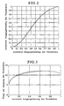
- Fig. 2 shows the control characteristic of a non-equalized high-frequency power amplifier 3, d. H. a high-frequency power amplifier 3 without Predistortion device 2.
- the input power and the output power are each normalized.
- Fig. 3 shows the phase at the output of the high-frequency power amplifier 3 as Function of the rated output power.
- the input signal of the in FIGS. 2 and 3 The simulation example shown is an amplitude-modulated single carrier signal.
- Fig. 2 it can be clearly seen that the modulation characteristic curve has an S-shaped curvature and is not linear. There are therefore considerable amplitude distortions.
- the phase characteristic curve shown in FIG. 3 shows that the initial phase differs considerably from that Output power of the high-frequency power amplifier 3 is dependent. Therefore occur significant phase distortions.
- phase 4 shows a multicarrier signal with a total of 8 useful carriers.
- the individual carriers are 4PSK modulated and can therefore assume four different phase states.
- the following random distribution of the phases assigned to the individual carriers was assumed: Frequency in MHz phase 396 0 397 0 398 ⁇ 399 1 ⁇ 2 ⁇ 401 0 402 ⁇ 403 1 ⁇ 2 ⁇ 404 0
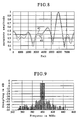
- Fig. 5 shows the output spectrum of the undistorted high frequency power amplifier 3, d. H. without pre-distortion of the input signal.
- the simulation made here shows only eight Carrier frequencies nevertheless the basic mode of operation of the invention.
- the output spectrum that, as expected, in addition to the eight Carrier frequencies of the useful signal an interference spectrum occurs that compared to the useful signal only has a shoulder distance of about 18 dB. Such a small shoulder distance is completely unsatisfactory in practice.
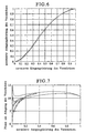
- FIG. 6 shows the associated modulation characteristic curve
- FIG. 7 shows the associated phase characteristic curve.
- the modulation characteristic has large non-linearities and the output phase depends to a large extent on the output power is.
- Fig. 8 shows the undistorted input envelope of the Multicarrier signal shown in Fig. 4.
- the reference numeral 41 is the input envelope one predistorted in amplitude with the method according to the invention Input signal shown.
- the output spectrum of the High-frequency power amplifier 3 results in a significantly increased shoulder distance of 36 dB between the useful signal and the interference spectrum.
- the control characteristic is essential due to the predistortion in comparison to FIG. 6 better linearized.
- Fig. 11 shows the output spectrum of the high frequency power amplifier 3 when in addition to amplitude predistortion, phase predistortion is made.
- the shoulder distance between the useful signal and the interference spectrum can be increased to approx. 40 dB.
- the phase characteristic curve shown in FIG. 12 shows the associated initial phase, which is approximately zero on average and significantly lower is subject to power-related fluctuations than that in Fig. 7 for the predistorted high-frequency power amplifier 3 shown phase characteristic.
Landscapes
- Physics & Mathematics (AREA)
- Nonlinear Science (AREA)
- Engineering & Computer Science (AREA)
- Power Engineering (AREA)
- Amplifiers (AREA)
Applications Claiming Priority (5)
| Application Number | Priority Date | Filing Date | Title |
|---|---|---|---|
| DE19732465 | 1997-07-28 | ||
| DE19732465 | 1997-07-28 | ||
| DE19813703A DE19813703A1 (de) | 1997-07-28 | 1998-03-27 | Meßverfahren und Meßeinrichtung zum Messen der Verzerrung eines Hochfrequenz-Leistungsverstärkers und Entzerrungsverfahren und Entzerrungseinrichtung zum automatischen Entzerren eines Hochfrequenz-Leistungsverstärkers |
| DE19813703 | 1998-03-27 | ||
| PCT/EP1998/004717 WO1999005784A1 (de) | 1997-07-28 | 1998-07-28 | Messverfahren und messeinrichtung zum messen der verzerrung eines hochfrequenz-leistungsverstärkers und entzerrungsverfahren und entzerrungseinrichtung zum automatischen entzerren eines hochfrequenz-leistungsverstärkers |
Publications (2)
| Publication Number | Publication Date |
|---|---|
| EP1000464A1 EP1000464A1 (de) | 2000-05-17 |
| EP1000464B1 true EP1000464B1 (de) | 2002-04-10 |
Family
ID=26038639
Family Applications (1)
| Application Number | Title | Priority Date | Filing Date |
|---|---|---|---|
| EP98943792A Expired - Lifetime EP1000464B1 (de) | 1997-07-28 | 1998-07-28 | Messverfahren und messeinrichtung zum messen der verzerrung eines hochfrequenz-leistungsverstärkers und entzerrungsverfahren und entzerrungseinrichtung |
Country Status (4)
| Country | Link |
|---|---|
| EP (1) | EP1000464B1 (enExample) |
| JP (1) | JP4287587B2 (enExample) |
| AT (1) | ATE216152T1 (enExample) |
| WO (1) | WO1999005784A1 (enExample) |
Families Citing this family (8)
| Publication number | Priority date | Publication date | Assignee | Title |
|---|---|---|---|---|
| EP1273098B1 (de) * | 2000-03-16 | 2004-05-06 | Rohde & Schwarz GmbH & Co. KG | Verfahren zur bestimmung von parametern eines n-tors |
| DE10136071A1 (de) † | 2001-07-25 | 2003-02-13 | Infineon Technologies Ag | Verfahren und Vorrichtung zur Kompensation eines Phasenfehlers eines Empfangs- und/oder Sendesystems mit I/Q-Schnittstelle |
| DE102005002207A1 (de) * | 2004-11-26 | 2006-06-01 | Rohde & Schwarz Gmbh & Co. Kg | Verfahren und System zur Ermittlung der Amplitude und/oder Phase des Ausgangssignals eines Übertragungsgliedes in Abhängigkeit der Amplitude des Eingangsignals |
| DE102005037880A1 (de) | 2005-05-19 | 2006-11-23 | Rohde & Schwarz Gmbh & Co. Kg | Verfahren und System zur Ermittlung der Amplitude und/oder Phase des Ausgangssignals eines Übertragungsgliedes in Abhängigkeit der Amplitude des Eingangssignals |
| JP2008177899A (ja) * | 2007-01-19 | 2008-07-31 | Sumitomo Electric Ind Ltd | 増幅回路及び無線通信装置 |
| JP5282172B2 (ja) * | 2010-12-23 | 2013-09-04 | 華為技術有限公司 | 信号処理装置及び信号処理方法 |
| CN104515944B (zh) * | 2014-12-18 | 2017-04-26 | 华中科技大学 | 一种基于pid反馈的预失真修正方法及led结温温度测量方法 |
| EP3306817B8 (en) | 2016-10-07 | 2021-04-21 | Rohde & Schwarz GmbH & Co. KG | Predistortion system and method |
Family Cites Families (1)
| Publication number | Priority date | Publication date | Assignee | Title |
|---|---|---|---|---|
| GB2204202B (en) * | 1987-04-28 | 1991-11-27 | Racal Communications Equip | Radio transmitters |
-
1998
- 1998-07-28 EP EP98943792A patent/EP1000464B1/de not_active Expired - Lifetime
- 1998-07-28 WO PCT/EP1998/004717 patent/WO1999005784A1/de not_active Ceased
- 1998-07-28 AT AT98943792T patent/ATE216152T1/de not_active IP Right Cessation
- 1998-07-28 JP JP2000504654A patent/JP4287587B2/ja not_active Expired - Fee Related
Also Published As
| Publication number | Publication date |
|---|---|
| ATE216152T1 (de) | 2002-04-15 |
| EP1000464A1 (de) | 2000-05-17 |
| JP4287587B2 (ja) | 2009-07-01 |
| WO1999005784A1 (de) | 1999-02-04 |
| JP2001511614A (ja) | 2001-08-14 |
Similar Documents
| Publication | Publication Date | Title |
|---|---|---|
| DE69324210T2 (de) | Automatische Kalibrierung der Quadraturbalance in einem kartesischen Verstärker | |
| DE60006674T2 (de) | Verminderung von signalverzerrungen | |
| DE602004001616T2 (de) | Hocheffizienter, linearer Leistungsverstärker | |
| DE69220514T2 (de) | Vorverzerrer und Methode für elektronische und optische Signallinearisierung | |
| DE60006102T2 (de) | Rundfunkübertragungssystem mit verteilter korrektur | |
| DE69820472T2 (de) | Linearisierungsverfahren und verstärkeranordnung | |
| DE60003954T2 (de) | Vorrichtung zur reduzierung von nachbarkanalstörungen durch vorlinearisierung und vorverzerrung | |
| DE69709560T2 (de) | Verfahren zur Korrektur von nichtlinearen Verzerrungen in einem Verstärker und ein solches Verfahren verwendenden Funksenders | |
| DE102004023480B4 (de) | Digitale Vorverzerrung zur Linearisierung von Leistungsverstärkern mit Asymmetrie-Eigenschaften | |
| DE68926603T2 (de) | Vorverzerrungskompensierter linearer Verstärker | |
| DE69032831T2 (de) | Vorverzerrungsschaltung für elektronische und optische Signalenlinearisierung | |
| DE10392344T5 (de) | Frequenzabhängige Amplitudenvorverzerrung zum Abschwächen von Störemissionen in Übertragungsnetzen | |
| US6239657B1 (en) | Method and device for measuring the distortion of a high-frequency power amplifier and method and means for automatically equalizing a high-frequency power amplifier | |
| DE10320420B4 (de) | Anordnung und Verfahren zur digitalen Vorverzerrung eines komplexen Basisband-Eingangssignals | |
| US8594231B2 (en) | Power series digital predistorter and distortion compensation control method therefor | |
| DE69623909T2 (de) | Verstärkereinrichtung | |
| EP0885482A1 (de) | Vorverzerrung für eine nichtlineare übertragungsstrecke im hochfrequenzbereich | |
| EP0465709A1 (de) | Verfahren zur Kompensation von Nichtlinearitäten einer Verstärkerschaltung | |
| JPH09512692A (ja) | 適応型前置補償器においてベースバンド・デジタル誤差信号を与える装置および方法 | |
| DE69907464T3 (de) | Verfahren und gerät zur kompensierung der verzerrung in i q modulatoren | |
| EP1000464B1 (de) | Messverfahren und messeinrichtung zum messen der verzerrung eines hochfrequenz-leistungsverstärkers und entzerrungsverfahren und entzerrungseinrichtung | |
| DE102008046689B4 (de) | Vorverzerrungslinearisierer | |
| EP1195005B1 (de) | Vorrichtung und verfahren zum vorverzerren eines über eine nicht-lineare übertragungsstrecke zu übertragenden übertragungssignals | |
| DE102004011494A1 (de) | Verfahren zur Erfassung von Signalabtastwerten | |
| DE69028835T2 (de) | Sendereinstellungssystem und -verfahren bei Funkverbindungen mit hoher Kapazität |
Legal Events
| Date | Code | Title | Description |
|---|---|---|---|
| PUAI | Public reference made under article 153(3) epc to a published international application that has entered the european phase |
Free format text: ORIGINAL CODE: 0009012 |
|
| 17P | Request for examination filed |
Effective date: 19990928 |
|
| AK | Designated contracting states |
Kind code of ref document: A1 Designated state(s): AT DE FI FR GB IT NL SE |
|
| GRAG | Despatch of communication of intention to grant |
Free format text: ORIGINAL CODE: EPIDOS AGRA |
|
| GRAG | Despatch of communication of intention to grant |
Free format text: ORIGINAL CODE: EPIDOS AGRA |
|
| GRAH | Despatch of communication of intention to grant a patent |
Free format text: ORIGINAL CODE: EPIDOS IGRA |
|
| 17Q | First examination report despatched |
Effective date: 20010920 |
|
| GRAH | Despatch of communication of intention to grant a patent |
Free format text: ORIGINAL CODE: EPIDOS IGRA |
|
| REG | Reference to a national code |
Ref country code: GB Ref legal event code: IF02 |
|
| GRAA | (expected) grant |
Free format text: ORIGINAL CODE: 0009210 |
|
| AK | Designated contracting states |
Kind code of ref document: B1 Designated state(s): AT DE FI FR GB IT NL SE |
|
| REF | Corresponds to: |
Ref document number: 216152 Country of ref document: AT Date of ref document: 20020415 Kind code of ref document: T |
|
| GBT | Gb: translation of ep patent filed (gb section 77(6)(a)/1977) |
Effective date: 20020412 |
|
| REF | Corresponds to: |
Ref document number: 59803758 Country of ref document: DE Date of ref document: 20020516 |
|
| ET | Fr: translation filed | ||
| PLBE | No opposition filed within time limit |
Free format text: ORIGINAL CODE: 0009261 |
|
| STAA | Information on the status of an ep patent application or granted ep patent |
Free format text: STATUS: NO OPPOSITION FILED WITHIN TIME LIMIT |
|
| 26N | No opposition filed |
Effective date: 20030113 |
|
| PGFP | Annual fee paid to national office [announced via postgrant information from national office to epo] |
Ref country code: SE Payment date: 20090727 Year of fee payment: 12 Ref country code: NL Payment date: 20090724 Year of fee payment: 12 Ref country code: GB Payment date: 20090724 Year of fee payment: 12 Ref country code: AT Payment date: 20090723 Year of fee payment: 12 |
|
| REG | Reference to a national code |
Ref country code: NL Ref legal event code: V1 Effective date: 20110201 |
|
| GBPC | Gb: european patent ceased through non-payment of renewal fee |
Effective date: 20100728 |
|
| PG25 | Lapsed in a contracting state [announced via postgrant information from national office to epo] |
Ref country code: NL Free format text: LAPSE BECAUSE OF NON-PAYMENT OF DUE FEES Effective date: 20110201 Ref country code: AT Free format text: LAPSE BECAUSE OF NON-PAYMENT OF DUE FEES Effective date: 20100728 |
|
| PG25 | Lapsed in a contracting state [announced via postgrant information from national office to epo] |
Ref country code: GB Free format text: LAPSE BECAUSE OF NON-PAYMENT OF DUE FEES Effective date: 20100728 |
|
| PG25 | Lapsed in a contracting state [announced via postgrant information from national office to epo] |
Ref country code: SE Free format text: LAPSE BECAUSE OF NON-PAYMENT OF DUE FEES Effective date: 20100729 |
|
| PGFP | Annual fee paid to national office [announced via postgrant information from national office to epo] |
Ref country code: FI Payment date: 20130722 Year of fee payment: 16 Ref country code: DE Payment date: 20130927 Year of fee payment: 16 |
|
| PGFP | Annual fee paid to national office [announced via postgrant information from national office to epo] |
Ref country code: FR Payment date: 20130719 Year of fee payment: 16 |
|
| PGFP | Annual fee paid to national office [announced via postgrant information from national office to epo] |
Ref country code: IT Payment date: 20130726 Year of fee payment: 16 |
|
| REG | Reference to a national code |
Ref country code: DE Ref legal event code: R119 Ref document number: 59803758 Country of ref document: DE |
|
| REG | Reference to a national code |
Ref country code: FR Ref legal event code: ST Effective date: 20150331 |
|
| PG25 | Lapsed in a contracting state [announced via postgrant information from national office to epo] |
Ref country code: FI Free format text: LAPSE BECAUSE OF NON-PAYMENT OF DUE FEES Effective date: 20140728 Ref country code: DE Free format text: LAPSE BECAUSE OF NON-PAYMENT OF DUE FEES Effective date: 20150203 Ref country code: IT Free format text: LAPSE BECAUSE OF NON-PAYMENT OF DUE FEES Effective date: 20140728 |
|
| REG | Reference to a national code |
Ref country code: DE Ref legal event code: R119 Ref document number: 59803758 Country of ref document: DE Effective date: 20150203 |
|
| PG25 | Lapsed in a contracting state [announced via postgrant information from national office to epo] |
Ref country code: FR Free format text: LAPSE BECAUSE OF NON-PAYMENT OF DUE FEES Effective date: 20140731 |