EP0999008B1 - Method of laser drilling an airfoil - Google Patents
Method of laser drilling an airfoil Download PDFInfo
- Publication number
- EP0999008B1 EP0999008B1 EP99307681A EP99307681A EP0999008B1 EP 0999008 B1 EP0999008 B1 EP 0999008B1 EP 99307681 A EP99307681 A EP 99307681A EP 99307681 A EP99307681 A EP 99307681A EP 0999008 B1 EP0999008 B1 EP 0999008B1
- Authority
- EP
- European Patent Office
- Prior art keywords
- passage
- airfoil
- blocking material
- gas
- pressure
- Prior art date
- Legal status (The legal status is an assumption and is not a legal conclusion. Google has not performed a legal analysis and makes no representation as to the accuracy of the status listed.)
- Expired - Lifetime
Links
Images
Classifications
-
- B—PERFORMING OPERATIONS; TRANSPORTING
- B23—MACHINE TOOLS; METAL-WORKING NOT OTHERWISE PROVIDED FOR
- B23K—SOLDERING OR UNSOLDERING; WELDING; CLADDING OR PLATING BY SOLDERING OR WELDING; CUTTING BY APPLYING HEAT LOCALLY, e.g. FLAME CUTTING; WORKING BY LASER BEAM
- B23K26/00—Working by laser beam, e.g. welding, cutting or boring
- B23K26/18—Working by laser beam, e.g. welding, cutting or boring using absorbing layers on the workpiece, e.g. for marking or protecting purposes
-
- B—PERFORMING OPERATIONS; TRANSPORTING
- B23—MACHINE TOOLS; METAL-WORKING NOT OTHERWISE PROVIDED FOR
- B23K—SOLDERING OR UNSOLDERING; WELDING; CLADDING OR PLATING BY SOLDERING OR WELDING; CUTTING BY APPLYING HEAT LOCALLY, e.g. FLAME CUTTING; WORKING BY LASER BEAM
- B23K26/00—Working by laser beam, e.g. welding, cutting or boring
- B23K26/36—Removing material
- B23K26/38—Removing material by boring or cutting
- B23K26/382—Removing material by boring or cutting by boring
- B23K26/389—Removing material by boring or cutting by boring of fluid openings, e.g. nozzles, jets
-
- Y—GENERAL TAGGING OF NEW TECHNOLOGICAL DEVELOPMENTS; GENERAL TAGGING OF CROSS-SECTIONAL TECHNOLOGIES SPANNING OVER SEVERAL SECTIONS OF THE IPC; TECHNICAL SUBJECTS COVERED BY FORMER USPC CROSS-REFERENCE ART COLLECTIONS [XRACs] AND DIGESTS
- Y10—TECHNICAL SUBJECTS COVERED BY FORMER USPC
- Y10T—TECHNICAL SUBJECTS COVERED BY FORMER US CLASSIFICATION
- Y10T29/00—Metal working
- Y10T29/49—Method of mechanical manufacture
- Y10T29/49316—Impeller making
- Y10T29/49336—Blade making
- Y10T29/49339—Hollow blade
- Y10T29/49341—Hollow blade with cooling passage
Definitions
- This invention relates to a method for laser drilling an airfoil which includes disposing material in passages of the airfoil for blocking a laser beam from striking the interior once the cooling air hole is drilled through the wall of the airfoil. More particularly, this invention relates to a method for disposing material in passages in the airfoil, such as a leading edge passage through an adjacent passage which is in flow communication with the leading edge passage.
- Airfoils for gas turbine engines are disposed in a flowpath for working medium gases. Examples of such airfoils are turbine blades and turbine vanes. The airfoils are bathed in hot gases as the gases are flowed through the engine. Cooling air is flowed though passages on the interior of the airfoil under operative conditions to keep the temperature of the airfoil, such as a turbine, vane or turbine blade, within acceptable limits.
- the airfoil may have cooling air holes extending from the interior to the exterior of the airfoil.
- the cooling air holes duct cooling air from passages on the interior of the airfoil through the hot walls to the exterior.
- the exhausted cooling air provides transpiration cooling as the air passes through the wall and film cooling with a film of cooling air on the exterior as the air is discharged from the airfoil.
- the film of cooling air provides a barrier between the airfoil and the hot, working medium gasses.
- the cooling air holes are small and may have diameters that are in a range of 0.3 to 0.5 millimeters (0.011 - 0.017 inches).
- the holes are drilled in predetermined patterns and are contoured to insure adequate cooling of the airfoil.
- One way to drill the holes uses a laser to direct a beam of coherent energy at the exterior of the airfoil.
- the intense radiation from the laser beam burns through the wall of the airfoil, leaving behind a hole which provides a satisfactory conduit for cooling air.
- the laser beam may strike adjacent structure on the other side of the cavity causing unacceptable damage to the airfoil.
- blocking material may be disposed in the cavity to block the laser beam from striking walls bounding the cavity after the beam penetrates through the airfoil wall.
- One approach is to leave disposed within the airfoil the ceramic casting core around which the blade is poured during the manufacturing process.
- the ceramic core provides a suitable blocking material.
- the ceramic core is subsequently removed by well known leaching techniques. This approach is described in U.S. Patent 5, 222, 617 entitled "Drilling Turbine Blades" issued to Gregore, Griffith and Stroud.
- the presence of the core after casting prevents initial inspection of the interior of the airfoil.
- the ceramic material may also be difficult to remove once the cooling air holes are drilled.
- the core is not available during repair processes for the airfoil which may require redrilling of the cooling air holes.
- a blocking material is wax or a wax-like material.
- the material is melted so that it may easily flow into interior passages, such as the leading edge passage of the airfoil.
- the temperature of the molten material above its melting point may exceed 121°C (250°F).
- the molten material may be poured or injected into the cavity or may even be sprayed or painted on the surface to be protected. However, the molten material may severely scald personnel working with the material.
- the wax may extend between two closely adjacent cooling air holes. The wax adjacent the first hole, which blocks the laser beam as the second hole is drilled, may melt as the first hole is drilled by the laser beam. This causes a void to form in the wax.
- the energy from the laser beam at the second hole may not be sufficiently dissipated by the wax as it passes through the portion of the passage having the void. Damage may occur to the airfoil as the second hole is drilled because the beam, after it penetrates through the wall at the second hole, may strike the interior wall of the airfoil.
- Still another approach is to use a masking agent, such as an epoxy resin, which is disposed in the airfoil in a fluid state.
- the epoxy resin is disposed in the airfoil by simply pouring the resin into the airfoil.
- the epoxy resin is at room temperature and poses no scalding hazard to personnel.
- the epoxy resin is further processed to harden the fluid and cause it to become a more solid material similar to the PTFE wax mentioned in U.S. Patent 5, 049,722.
- the resin is relatively viscous compared to molten wax and has difficulty in flowing through small connecting passages on the interior of the airfoil.
- air bubbles tend to form in blocking material in blind cavities, such as the leading edge passage, and in passages which are blocked by the in flowing viscous material. These air bubbles result from not flowing enough epoxy resin into the leading edge region to eliminate the voids.
- the structural design of the airfoil may cause the airfoil to trap an air bubble with structure within the leading edge passage.
- EP 0854005 A2 discloses a method of forming and inspecting beam drilled holes in an airfoil which includes flowing blocking material in a first environment having a gas at a first pressure P 1 into a leading edge passage and into an adjacent passage that traps gas in the passages.
- the present invention is characterised over EP 0854005 in that it provides a method for disposing blocking material through a plurality of impingement holes in a leading edge passage of an airfoil and by displacing the blocking material by placing the airfoil in a second environment having a gas at a second pressure P 2 which is less than the first pressure P 1 , to form a partial vacuum which increases the volume of the gas escaping through the passages.
- the method includes flowing a fluid blocking material formed of a mixture of epoxy resin and a curing agent at room temperature into the airfoil in an environment that is at room temperature.
- enough fluid mixture is mixed for the airfoils such that the time of filling the airfoils is approximately equal to the amount of time that the filled airfoils spend at a reduced pressure to limit the length of time the epoxy resin and curing agent are interacting prior to disposing the mixture in a reduced atmosphere environment.
- the blocking material hardens in an environment having a pressure which is greater than the second pressure P 2 to decrease the volume of any trapped gas in the blocking material disposed within the airfoil.
- a primary feature of the present invention is the step of forming gas bubbles having increased volume through use of a reduced pressure, with the expanded bubbles forcing blocking material in fluid form through impingement holes that connect a second passage to the leading edge passage of the airfoil.
- Another preferred feature of the present invention is the pressure at which the hardening step is carried out which compresses the volume of any pockets of gas molecules remaining in the blocking material.
- Still another feature of one embodiment of the present invention is the level of temperature of the blocking material flowed into the airfoil.
- Another preferred feature of the present invention is the step of removing the blocking material by heating the blocking material to an elevated temperature to vaporize the blocking material.
- a principal advantage of the present invention is the speed at which airfoils may be filled with a blocking material which results from forcing the blocking material into the leading edge region of the airfoil through small impingement holes. Another advantage is the cost of performing the drilling function which results from the ease of handling the airfoils filled with blocking material and avoiding scraped parts or parts needing rework which results from forcing enough blocking material at room temperature into the leading edge region. Another principal advantage of the present invention is the health and safety of personnel using the method by avoiding the possibility of scalding of personnel handling blocking material and airfoils filled with blocking material which results from using a fluid epoxy resin and hardener at room temperature for the blocking material during the filling operation. Still another advantage of the present invention is the ease of removing the blocking material after completion of the drilling operation by heating the filled airfoil after drilling to a temperature which vaporizes the blocking material.
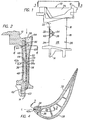
- Fig. 1 is a side elevation view of an airfoil for a gas turbine engine as represented by stator vane 10 for such an engine.
- airfoil includes without limitation turbine blades and turbine vanes and refers to all portions of the turbine blade and the stator vane including their flow directing surfaces, platforms and buttresses.
- the airfoil has an outer end 12 and an inner end 14.
- the airfoil has a trailing edge region 16 having a trailing edge 18 which extends in the spanwise direction.
- a leading edge region 22 is spaced chordwisely forward of the trailing edge region.
- the leading edge region has a leading edge 24 which extends in the spanwise direction.
- the airfoil 10 further has a flow-directing surface 26 which extends between the inner end 14 and the outer end 12.
- the flow-directing surface includes a suction sidewall 28 and a pressure sidewall 32.
- the suction sidewall and pressure sidewall are joined at the leading edge 24 and the trailing edge 18 leaving a cavity 34 for cooling air disposed therebetween.
- the airfoil 10 has a first internal wall 36 disposed in the cavity 34.
- the first wall 36 is spaced chordwise from the leading edge 24.
- the first wall extends between the suction sidewall 28 and the pressure sidewall 32 leaving a first passage 38 for cooling air therebetween.
- the first passage extends spanwise in the leading edge region 22.
- cooling air holes 42 are drilled by appropriate means. The cooling air holes extend through the sidewalls to the interior of the airfoil in the leading edge region and in other regions of the airfoil (not shown).
- the first passage is not in flow communication with the exterior of the airfoil through the leading edge region in a partially formed airfoil.
- Fig. 2 is a cross-sectional view of a portion of a partially formed airfoil 10 corresponding to the finished airfoil 10 shown in Fig. 1. A part of the partially formed airfoil is broken away to show the leading edge region of the airfoil. As shown in Fig. 2, the airfoil does not yet have cooling air holes 42 drilled in the leading edge region.
- the airfoil has a second internal wall 44 extending chordwise to divide the first spanwise passage 38 into a first spanwise region 46 and a second spanwise region 48.
- the airfoil 10 has a third internal wall 52 spaced chordwise from the leading edge 24 and from the first wall 36.
- the third internal wall extends between the sidewalls 28, 32 leaving a second passage 54 extending spanwise adjacent to the first passage 38.
- a plurality of impingement holes 56 extend through the first wall to place the first passage in flow communication with the second passage.
- a first opening 58 at the outer end 12 and a second opening 62 at the inner end 14 of the airfoil place the second passage in flow communication with the exterior of the airfoil.
- a cover 63 extends over the second opening to seal the opening during manufacture.
- a blocking material 64 in the fluid state is shown disposed in the leading edge region 22. Bubbles of gas are trapped during filling of the airfoil with blocking material. The bubbles are shown in schematic fashion as represented by the gas bubble 66, the gas bubble 68 and the gas bubble 72.
- the first passage 38 is always in fluid communication and generally in gas communication with the second passage 54 through the impingement holes 56 depending on the orientation of the airfoil. As a result, the first passage and the second passage generally have flow communication with the exterior of the airfoil through the first opening 58 at the outer end 12 and the second opening 62 at the inner end 14. However, regions of reduced circulation form for the gas as blocking material in fluid form is flowed during filling into the second passage and into the first passage from the second passage.
- impingement hole 56a is closest to the second wall, and is spaced spanwise from the second wall.
- the fluid blocking material might fill to this level leaving a region of restricted circulation R for gas above the hole.
- the impingement hole places a portion of the second region that is closest to the region R in gas communication with the second passage but does not extend to the region R.
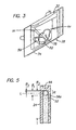
- Fig. 3 is a view from above of the first outer end 12 of the airfoil 10 taken along the lines 3-3 of Fig. 1.
- Fig. 1 and Fig. 3 show the relationship to the outer end 12 of a first dam 74 (shown in phantom on Fig. 1 and in full on Fig. 3) on the suction side of the airfoil.
- a second dam 76 on the pressure side of the airfoil faces the first dam.
- a cover or a barrier (shown in phantom) 84 extends over certain other openings 78, 82 in the airfoil to block the flow of fluid blocking material to these locations. The dams and the barriers cooperate with the first side of the airfoil to form a bowl 86 to receive and funnel the fluid toward the first opening.
- Fig. 4 is a cross sectional view through the airfoil shown in Fig. 2 along the lines 4-4.
- the method of drilling a cooling hole 42 at the leading edge 24 of the airfoil employs a laser beam of focused coherent light.
- the laser beam impacts the exterior of the airfoil.
- Fig. 4 shows the relationship of a laser beam to the exterior of the airfoil and to the first passage 38 during the process of drilling the cooling air hole 42.
- the laser beam is schematically represented by the center line L.
- the line of strike of the laser beam is coincident with the center line L.
- the line of the laser beam is shown extending across the first passage 38 to strike the first wall 36 as if blocking material were not present.
- the laser beam may strike the exterior wall of the airfoil or, depending on the orientation of the cooling air hole, the first internal wall in the leading edge region. Unless blocking material absorbs and dissipates the energy of the beam. Holes may be drilled or partially drilled into the first wall or into the exterior wall in this region. These holes may result in scrapping of the airfoil or costly rework of the airfoil.
- the method of drilling the cooling air hole 42 requires disposing a blocking material in regions of the airfoil adjacent the location of cooling air holes in the leading edge region.
- This includes orienting the airfoil 10 with respect to a source of blocking material such that the blocking material may be flowed into the second passage 54 of the airfoil and thence into the first passage 38 of the airfoil.
- the airfoil is disposed in a fixture for holding the airfoil that tilts the inner end of the airfoil rearwardly about five degrees (5°) from the vertical.
- the first passage 38 in the leading edge region 22 is a blind cavity having no exit holes (cooling air holes 42) in the leading edge region.
- the impingement holes 56 extending between the first passage and the second passage 54 must provide both an inlet for the blocking material 64 and an exit for trapped gases on the interior of the airfoil.
- the step of flowing blocking material 64 into the second passage 54 and thence into the first passage 38 typically takes place in a first environment.
- environment such as first environment, second environment, and third environment
- gas includes a gas made up of molecules of a single type of atom, such as argon, or many types of atoms, such as air.
- the gas in the first environment is air at a first pressure P 1 and a first temperature T 1 .
- the first pressure P 1 is atmospheric pressure, approximately 101 kPA (14.7 psia) and the first temperature is approximately equal to room temperature.
- Room temperature typically lies in a range of about 21°C (70°F) to 27°C (80°F).
- One material which was found acceptable for blocking material is a curable fluid epoxy resin and fluid curing agent.
- the mixture is cured prior to the drilling operation.
- the curing agent is EPI-CURE Curing Agent 3140 material. Equal volume parts of the resin and the curing agent are mixed together.
- the curing agent is a low viscosity curative, applicable typically to adhesive flooring and general coatings. At temperatures of about 27°C (80°F), the viscosity of the curing agent is about 3 to 6 Pascal-seconds (3,000-6,000 centipoise) and the viscosity of the resin is about 0.5 to 0.7 Pascal-seconds(500-700 centipoise).
- the mixture of the resin and curing agent at room temperature has a viscosity that approximates that of molasses, and may lie in a range of about 1.75 Pascal-seconds(1750 centipoise) to about 3.4 Pascal-seconds (3400 centipoise).
- the method Prior to pouring the molasses-like mixture of epoxy resin and curing agent into the first passage, the method includes forming the dams 74, 76 and installing covers at selected locations of the airfoil.
- the method includes forming the bowl 86 at the outer end of the vane.
- the bowl is adjacent the first opening 58 of the vane and is formed by applying aluminum tape to the sides of the airfoil.
- the tape forms a dam 74 on the suction side and dam 76 on the pressure side of the end of the vane.
- Aluminum Foil Glass Cloth Tape Part Number 2925-7, from Furon Inc., 14 McCaffrey Street, Hoosick Falls, New York 12090.
- the height H1 of the tape is about 9.5 millimeters (3/8 of an inch) above the portion of the airfoil which is adjacent to the first opening.
- the airfoil has other openings 78, 82 at the outer end of the vane.
- the method includes blocking these other openings if necessary.
- the same aluminum tape is used for the cover 63 at the second opening 62. The opening is covered prior to flowing blocking material into the second passage 54.
- Blocking material is poured into the bowl formed by the dams and into the second passage until the blocking material reaches a height above the opening.
- the height the blocking material reaches above the opening is less than the height of the dam and typically is about 6.4 millimeters (.25 of an inch).
- the blocking material traps gas, such as the air of the first environment, in pockets in the second passage.
- the aluminum tape might be applied to provide a barrier at the second opening after the blocking material has flowed into the second passage. This would ensure that as much air as possible was driven out of the second passage but is time consuming because the airfoil must be manipulated and cleaned of any resin that reaches the exterior of the airfoil. This would occur prior to substantial amounts of the blocking material flowing into the first passage.
- Enough fluid blocking material is mixed so that it is all substantially consumed in filling the next batch of airfoils going into the vacuum oven.
- the amount of time filling a batch of the airfoils is about equal to the time spent in the partial vacuum by the previous batch of filled airfoils.
- the airfoil filled with blocking material is disposed in a vacuum oven having a second environment of air at a second temperature T 2 and a second pressure P 2 to form a partial vacuum for a period of about twenty (20) to thirty (30) minutes.
- the second pressure P 2 is less than the first pressure P 1 (typically, atmospheric pressure) of the first environment.
- the second pressure is typically less than 16.7 kPa (125 Torr) that is, less than about 2.5 psia.
- the temperature T 2 . of the atmosphere at the partial vacuum is about room temperature.
- the temperature T 2 in alternate embodiments of the invention might increase above the temperature T 1 as long as hardening of the blocking material is not increased by an amount that would capture air bubbles in the leading edge region as the air is evacuated from the blocking material into the second environment.
- a temperature T 2 higher than the temperature T 1 might be advantageous in situations where the viscosity of the blocking material decreases with temperature.
- the method includes orienting the airfoil such that buoyant forces act on the bubbles of gas trapped in the blocking material.
- the vane is a free standing structure supported by its inner end and may be placed in the vacuum oven without further support.
- the vane is disposed in a fixture which cants the second end of the vane rearwardly about five (5) degrees. Once such fixture has a pair of parallel rods which each engage the underside of the outer end of the vane platform. This avoids the need for special fixturing , speeding handling of the vanes and reducing handling costs.
- the partial vacuum causes the air bubble 68 to expand, increasing the buoyant forces acting on the bubble.
- An expanded bubble in the first passage 38 is urged by buoyant forces from the first passage into the second passage 54.
- This expanded bubble joins other expanded bubbles disposed in the second passage.
- the bubbles urge the blocking material to flow into the first passage through the impingement holes 56 extending between the second passage and the first passage. Blocking material urged into the first passage in turn helps force air from the first passage through the impingement holes into the second passage increasing the effect of the bubbles passing through the second passage and urging more blocking medium into the first passage.
- the airfoil filled with blocking material is disposed in a third environment.
- the third environment has a gas at a third pressure P 3 which is greater than the second pressure P 2 .
- the gas is typically air at a temperature T 3 which is greater than the temperature T 2 .
- the temperature used with this particular mixture of epoxy resin and curing agent is in a range of about 107°C (225°F) to 135°C (275°F).
- the environment is at a temperature of about 121°C (250°F).
- the mixture of epoxy resin and curing agent is held in this temperature range for about twenty (20) minutes to thirty (30) minutes causing the mixture to harden. This is followed by a curing time in a fourth environment of about forty-eight hours at room temperature and atmospheric pressure to finally cure the mixture of epoxy resin and curing agent.
- An alternate embodiment of the present invention might use another material such as wax. In such a case, the step of flowing the blocking material into the second passage in a first environment might be carried out at a higher temperature. Another approach would use wax in the molten state at such an elevated temperature that the heat in the wax keeps the wax molten as it is flowed into the vane.
- the step of disposing the filled airfoil in a second environment would be carried out in a vacuum oven in a partial vacuum at an elevated temperature to keep the wax molten.
- the step of disposing the airfoil filled with wax in the third environment for curing would take place at a temperature T 3 lower than the temperature T 2 and at a pressure P 3 which is higher than the pressure P 2 to solidify the wax.
- a particular advantage of the present method occurs in filling articles with blocking material that have regions of reduced circulation such as the region R shown in Fig. 2 and shown in an enlarged view in Fig. 5.
- regions of reduced circulation such as the region R shown in Fig. 2 and shown in an enlarged view in Fig. 5.
- the phenomena is not well understood, empirical data suggests that the following occurs in this region. It is possible for the region R to trap a bubble of gas which is coextensive in spanwise height with the height B of the region R.
- Disposing the airfoil filled with blocking material in the second environment at a pressure which is less than approximately 16.7 kPa (125 Torr) decreases the external pressure of the gas in the environment on the blocking material. This, in turn, decreases the pressure on the trapped gas in the bubble.
- the ideal-gas law provides a good approximation of the effect of pressure of the environment and temperature of the blocking material on the volume of the trapped bubble.
- the ideal-gas law suggests that decreasing the external pressure by a factor of six (from 101 kPa (760 Torr) to less than 16.7 kPa (125 Torr)) will result in a sixfold increase in volume of the trapped gas.
- the bubble In the absence of the array of impingement holes 56, the bubble would expand spanwisely to a spanwise height B 2 in the second portion of the passage.
- the new spanwise height B 2 with the partial vacuum would be about six (6) times greater than the spanwise height B 1 .
- Impingement holes are not absent from the airfoil. In fact, there are impingement cooling air holes which place the first passage in flow communication with the exterior of the airfoil. Decreasing the pressure to pressure P 2 allows the trapped gas to expand to the impingement hole 56a which is closest to the second wall 44 and which is adjacent to the region R. The buoyant forces acting on the trapped bubble 72 push the bubble out through the impingement hole 56a and into the second passage and thence to the exterior of the airfoil. This continues until the gas bubble no longer extends out of the region R. Thus at the reduced pressure P 2 , the trapped gas bubble still extends for the same spanwise height B 1 but many molecules of air have escaped.
- Disposing the airfoil filled with a blocking material in the third environment at the third pressure P 3 causes the volume of the gas to decrease to a spanwise height B 3 and to less than a sixth of its original volume.
- the trapped gas still displaces a small portion of the blocking material and forms a void of height B 3 .
- the shrunken void is not aligned with the drilling axis L of the laser beam for the cooling air hole 42a which extends through the leading edge of the airfoil between the impingement hole and the second wall 44. Heating the blocking material during the hardening step does cause the volume of the gas to increase above the temperature T 2 .
- the volume increase is small (approximately a two to threefold increase in volume depending on the temperature of the gas in the bubble) compared to the decrease in volume that results from decreasing the pressure to a sixth (1/6) of its normal value during the process of removing the trapped gas.
- the laser beam L does not intercept the void formed by the bubble and the laser beam does not strike the wall.
- This method may also be applied to any blocking material which is fluid in form and hardened.
- a blocking material which has a wax base is evacuated in the second environment at an elevated temperature to keep the wax in fluid form and then cooled to room temperature to harden the wax.
- both the pressure and temperature of the second and third environments act to reduce the volume of the trapped gas during the evacuation and hardening process.
- the hardening process is completed by curing the resin mixture at room temperature and atmosphere pressure for forty-eight (48) hours in a fourth environment. Once the hardening process is complete, the blocking material maintains its shape by reason of its increased resistance to differences in ambient pressure.
- the epoxy resin is particularly resistant to any effect of pressure but it is believed that wax-like material would work equally well.
- the method includes the step of drilling cooling air holes through the external wall of the airfoil into the leading edge cavity and at such other locations as may be required. This step is carried out using conventional laser drilling techniques.
- the interior of the airfoil is cleaned of the blocking material by placing the airfoil in a fifth environment having air, such as an oven, and heating the environment to a temperature of 705°C (1,300°F).
- the epoxy resin is vaporized leaving at most some fine particles which may pass through the cooling air holes.
- This is followed by performing a water flow test on the airfoil to ensure that the cooling air holes are of acceptable size. The water flow test flows water through the airfoil and would carry any oxidized particles of resin away if any such particles exist.
- An advantage of the present invention is the reduced cost of fabricating the airfoil which results from using a blocking material which does not require extensive manipulation of the airfoil in many directions to remove trapped gas bubbles with buoyant forces.
- Another advantage in one embodiment is the reduced level of risk of scalding personnel handling the airfoil during the filling operation which results from using an epoxy resin and curing agent at room temperature.
- Another advantage is the level of cost for the process which results from avoiding costs associated with scrapped airfoils or the costs associated with reworking airfoils which may be damaged during the drilling operation but which are reworked to bring them into acceptable configuration.
- Still another advantage is the removal of the blocking material by heating the airfoil to an elevated temperature which vaporizes most, if not all, of the blocking material. Any fine particles of powder left behind are easily washed away during further processing of the airfoil.
Landscapes
- Engineering & Computer Science (AREA)
- Physics & Mathematics (AREA)
- Optics & Photonics (AREA)
- Plasma & Fusion (AREA)
- Mechanical Engineering (AREA)
- Turbine Rotor Nozzle Sealing (AREA)
Applications Claiming Priority (2)
| Application Number | Priority Date | Filing Date | Title |
|---|---|---|---|
| US09/162,832 US5914060A (en) | 1998-09-29 | 1998-09-29 | Method of laser drilling an airfoil |
| US162832 | 1998-09-29 |
Publications (3)
| Publication Number | Publication Date |
|---|---|
| EP0999008A2 EP0999008A2 (en) | 2000-05-10 |
| EP0999008A3 EP0999008A3 (en) | 2001-01-24 |
| EP0999008B1 true EP0999008B1 (en) | 2005-02-02 |
Family
ID=22587314
Family Applications (1)
| Application Number | Title | Priority Date | Filing Date |
|---|---|---|---|
| EP99307681A Expired - Lifetime EP0999008B1 (en) | 1998-09-29 | 1999-09-29 | Method of laser drilling an airfoil |
Country Status (5)
| Country | Link |
|---|---|
| US (1) | US5914060A (hu) |
| EP (1) | EP0999008B1 (hu) |
| JP (1) | JP2000110506A (hu) |
| DE (1) | DE69923521T2 (hu) |
| SG (1) | SG73650A1 (hu) |
Families Citing this family (18)
| Publication number | Priority date | Publication date | Assignee | Title |
|---|---|---|---|---|
| US6329633B1 (en) * | 1998-11-20 | 2001-12-11 | United Technologies Corporation | Method and material for processing a component for laser machining |
| US6251315B1 (en) * | 1998-11-20 | 2001-06-26 | United Technologies Corporation | Method for disposing a laser blocking material on the interior of an airfoil |
| US6359254B1 (en) * | 1999-09-30 | 2002-03-19 | United Technologies Corporation | Method for producing shaped hole in a structure |
| US6339208B1 (en) * | 2000-01-19 | 2002-01-15 | General Electric Company | Method of forming cooling holes |
| US6441341B1 (en) | 2000-06-16 | 2002-08-27 | General Electric Company | Method of forming cooling holes in a ceramic matrix composite turbine components |
| GB2365497A (en) * | 2000-08-08 | 2002-02-20 | Rolls Royce Plc | Gas turbine aerofoil cooling with pressure attenuation chambers |
| SE521759C2 (sv) * | 2000-11-09 | 2003-12-02 | Volvo Aero Corp | Förfarande för framställning av ett blad till en gasturbinkomponent samt framställning av en gasturbinkomponent |
| GB2410204B (en) * | 2001-05-30 | 2005-10-19 | Btu Internat Inc | Filtering apparatus |
| US20050248060A1 (en) * | 2002-06-28 | 2005-11-10 | 3M Innovative Properties Company | Manufacture of valve stems |
| US7387817B2 (en) * | 2005-03-30 | 2008-06-17 | Pratt & Whitney Canada Corp. | Method for masking a workpiece before encapsulation in a casting block |
| DE102006010927A1 (de) * | 2006-03-09 | 2007-09-13 | Mtu Aero Engines Gmbh | Gasturbinenbauteil sowie Verfahren zur Bearbeitung von Gasturbinenbauteilen im Rahmen der Herstellung oder Instandsetzung dieser Gasturbinenbauteile |
| US7686582B2 (en) * | 2006-07-28 | 2010-03-30 | United Technologies Corporation | Radial split serpentine microcircuits |
| DE102006061444A1 (de) * | 2006-12-23 | 2008-06-26 | Mtu Aero Engines Gmbh | Verfahren und Vorrichtung zur Aufbringung eines Schutzmediums auf eine Turbinenschaufel sowie Verfahren zur Einbringung von Kühlbohrungen in eine Turbinenschaufel |
| EP2335855A1 (de) * | 2009-12-04 | 2011-06-22 | Siemens Aktiengesellschaft | Füllstoff beim Bohren von Durchgangslöchern von hohlen Bauteilen, ein Verfahren und Vorrichtung dafür |
| US8525073B2 (en) * | 2010-01-27 | 2013-09-03 | United Technologies Corporation | Depth and breakthrough detection for laser machining |
| US9862057B2 (en) | 2012-12-12 | 2018-01-09 | United Technologies Corporation | Vacuum degassing laser-blocking material system and process |
| US10668654B2 (en) | 2015-01-30 | 2020-06-02 | Raytheon Technologies Corporation | Method for disposing a blocking material |
| JP7469917B2 (ja) * | 2020-03-13 | 2024-04-17 | 本田技研工業株式会社 | 孔開け加工方法 |
Family Cites Families (16)
| Publication number | Priority date | Publication date | Assignee | Title |
|---|---|---|---|---|
| DE1227228B (de) * | 1958-09-19 | 1966-10-20 | Wacker Chemie Gmbh | Verfahren zur Herstellung von Schaumkoerpern aus Polyvinylchloridpasten |
| FR2608089A1 (fr) * | 1986-12-12 | 1988-06-17 | Delorme Patrick | Procede de production de produits decoratifs, notamment a base de fragments ou morceaux de bois, et produits obtenus |
| US5011626A (en) * | 1988-06-13 | 1991-04-30 | Rolls-Royce Inc. | Barrier materials for laser drilling |
| US4873414A (en) * | 1988-06-13 | 1989-10-10 | Rolls Royce Inc. | Laser drilling of components |
| GB8921040D0 (en) * | 1989-09-16 | 1989-11-01 | Rolls Royce Plc | Laser barrier material |
| US5140127A (en) * | 1989-09-20 | 1992-08-18 | Rolls-Royce Plc | Laser barrier material |
| GB2241186A (en) * | 1990-02-24 | 1991-08-28 | Rolls Royce Plc | Anti-sputtercoating |
| JPH0441090A (ja) * | 1990-06-06 | 1992-02-12 | Toshiba Corp | レーザ穴あけ方法 |
| GB2249279B (en) * | 1990-10-17 | 1994-01-05 | Rolls Royce Plc | Improvements in or relating to drilling turbine blades |
| JPH04172194A (ja) * | 1990-11-05 | 1992-06-19 | Mitsubishi Heavy Ind Ltd | 中空部材のレーザ穴明時の内面保護方法 |
| JP3158667B2 (ja) * | 1991-08-01 | 2001-04-23 | セイコーエプソン株式会社 | 液晶表示素子の製造方法及び液晶表示素子の再生方法 |
| US5368634A (en) * | 1993-07-26 | 1994-11-29 | Hughes Aircraft Company | Removing bubbles from small cavities |
| JPH07279611A (ja) * | 1994-04-07 | 1995-10-27 | Ishikawajima Harima Heavy Ind Co Ltd | タービン翼の冷却孔加工方法 |
| GB9514447D0 (en) * | 1995-07-14 | 1995-09-13 | Rolls Royce Plc | Laser barrier material and method |
| US5776222A (en) * | 1996-01-31 | 1998-07-07 | Lucent Technologies Inc. | Method of eliminating light scattering bubbles in optical fiber preforms |
| US5773790A (en) * | 1997-01-21 | 1998-06-30 | General Electric Company | Beam blocking material and method for beam drilling and inspecting cooling holes |
-
1998
- 1998-09-29 US US09/162,832 patent/US5914060A/en not_active Expired - Lifetime
-
1999
- 1999-05-28 SG SG1999002878A patent/SG73650A1/en unknown
- 1999-07-23 JP JP11208464A patent/JP2000110506A/ja active Pending
- 1999-09-29 EP EP99307681A patent/EP0999008B1/en not_active Expired - Lifetime
- 1999-09-29 DE DE69923521T patent/DE69923521T2/de not_active Expired - Lifetime
Also Published As
| Publication number | Publication date |
|---|---|
| DE69923521D1 (de) | 2005-03-10 |
| DE69923521T2 (de) | 2006-01-12 |
| SG73650A1 (en) | 2000-06-20 |
| EP0999008A2 (en) | 2000-05-10 |
| JP2000110506A (ja) | 2000-04-18 |
| US5914060A (en) | 1999-06-22 |
| EP0999008A3 (en) | 2001-01-24 |
Similar Documents
| Publication | Publication Date | Title |
|---|---|---|
| EP0999008B1 (en) | Method of laser drilling an airfoil | |
| EP0992315B1 (en) | Method for reducing void volumes in cavities for laser drilling | |
| JP3069563B2 (ja) | エアフォイルにレ―ザ遮断材料を配置するための固定具 | |
| US7192622B2 (en) | Process of masking cooling holes of a gas turbine component | |
| EP1497476B1 (en) | Process of masking cooling holes of a gas turbine component | |
| US5222617A (en) | Drilling turbine blades | |
| JP2520672B2 (ja) | 金属物品の溶接による修理方法 | |
| EP1387040B1 (en) | Method of protecting partial areas of a component | |
| US7610946B2 (en) | Cooled turbine blade cast tip recess | |
| EP1118419A2 (en) | Method of forming cooling holes | |
| EP1764171A1 (en) | Method of forming a cast component | |
| KR20060115588A (ko) | 초합금 수리 방법 및 삽입체 | |
| EP3059044B1 (en) | Component repair using confined laser drilling | |
| KR20070025935A (ko) | 초합금 수리 방법 | |
| US6177038B1 (en) | Method for orienting an airfoil for processing and for forming a mask for the airfoil | |
| JP2001025863A (ja) | 溶接方法および溶接用アセンブリ | |
| JP3069564B2 (ja) | エアフォイルにレ―ザ遮断材料を配置するための工具 | |
| US6329633B1 (en) | Method and material for processing a component for laser machining | |
| US6251315B1 (en) | Method for disposing a laser blocking material on the interior of an airfoil | |
| EP3050668B1 (en) | Method for disposing a blocking material |
Legal Events
| Date | Code | Title | Description |
|---|---|---|---|
| PUAI | Public reference made under article 153(3) epc to a published international application that has entered the european phase |
Free format text: ORIGINAL CODE: 0009012 |
|
| AK | Designated contracting states |
Kind code of ref document: A2 Designated state(s): DE FR GB |
|
| AX | Request for extension of the european patent |
Free format text: AL;LT;LV;MK;RO;SI |
|
| PUAL | Search report despatched |
Free format text: ORIGINAL CODE: 0009013 |
|
| AK | Designated contracting states |
Kind code of ref document: A3 Designated state(s): AT BE CH CY DE DK ES FI FR GB GR IE IT LI LU MC NL PT SE |
|
| AX | Request for extension of the european patent |
Free format text: AL;LT;LV;MK;RO;SI |
|
| RIC1 | Information provided on ipc code assigned before grant |
Free format text: 7B 23K 26/00 A, 7B 23K 26/18 B |
|
| 17P | Request for examination filed |
Effective date: 20010717 |
|
| AKX | Designation fees paid |
Free format text: DE FR GB |
|
| 17Q | First examination report despatched |
Effective date: 20030401 |
|
| GRAP | Despatch of communication of intention to grant a patent |
Free format text: ORIGINAL CODE: EPIDOSNIGR1 |
|
| RIN1 | Information on inventor provided before grant (corrected) |
Inventor name: WALLER, JAMES F., JR. Inventor name: JONES, JAMES D. Inventor name: FLIS, JEFFREY D. |
|
| GRAS | Grant fee paid |
Free format text: ORIGINAL CODE: EPIDOSNIGR3 |
|
| GRAA | (expected) grant |
Free format text: ORIGINAL CODE: 0009210 |
|
| AK | Designated contracting states |
Kind code of ref document: B1 Designated state(s): DE FR GB |
|
| REG | Reference to a national code |
Ref country code: GB Ref legal event code: FG4D |
|
| REF | Corresponds to: |
Ref document number: 69923521 Country of ref document: DE Date of ref document: 20050310 Kind code of ref document: P |
|
| PLBE | No opposition filed within time limit |
Free format text: ORIGINAL CODE: 0009261 |
|
| STAA | Information on the status of an ep patent application or granted ep patent |
Free format text: STATUS: NO OPPOSITION FILED WITHIN TIME LIMIT |
|
| ET | Fr: translation filed | ||
| 26N | No opposition filed |
Effective date: 20051103 |
|
| PGFP | Annual fee paid to national office [announced via postgrant information from national office to epo] |
Ref country code: FR Payment date: 20110922 Year of fee payment: 13 |
|
| PGFP | Annual fee paid to national office [announced via postgrant information from national office to epo] |
Ref country code: GB Payment date: 20120926 Year of fee payment: 14 |
|
| PGFP | Annual fee paid to national office [announced via postgrant information from national office to epo] |
Ref country code: DE Payment date: 20120927 Year of fee payment: 14 |
|
| REG | Reference to a national code |
Ref country code: FR Ref legal event code: ST Effective date: 20130531 |
|
| PG25 | Lapsed in a contracting state [announced via postgrant information from national office to epo] |
Ref country code: FR Free format text: LAPSE BECAUSE OF NON-PAYMENT OF DUE FEES Effective date: 20121001 |
|
| GBPC | Gb: european patent ceased through non-payment of renewal fee |
Effective date: 20130929 |
|
| REG | Reference to a national code |
Ref country code: DE Ref legal event code: R119 Ref document number: 69923521 Country of ref document: DE Effective date: 20140401 |
|
| PG25 | Lapsed in a contracting state [announced via postgrant information from national office to epo] |
Ref country code: GB Free format text: LAPSE BECAUSE OF NON-PAYMENT OF DUE FEES Effective date: 20130929 |
|
| PG25 | Lapsed in a contracting state [announced via postgrant information from national office to epo] |
Ref country code: DE Free format text: LAPSE BECAUSE OF NON-PAYMENT OF DUE FEES Effective date: 20140401 |