EP0997228A1 - Machine à meuler des verres à lunettes - Google Patents
Machine à meuler des verres à lunettes Download PDFInfo
- Publication number
- EP0997228A1 EP0997228A1 EP99308533A EP99308533A EP0997228A1 EP 0997228 A1 EP0997228 A1 EP 0997228A1 EP 99308533 A EP99308533 A EP 99308533A EP 99308533 A EP99308533 A EP 99308533A EP 0997228 A1 EP0997228 A1 EP 0997228A1
- Authority
- EP
- European Patent Office
- Prior art keywords
- lens
- spindle
- tool
- cutting
- axis
- Prior art date
- Legal status (The legal status is an assumption and is not a legal conclusion. Google has not performed a legal analysis and makes no representation as to the accuracy of the status listed.)
- Withdrawn
Links
Images

Classifications
-
- B—PERFORMING OPERATIONS; TRANSPORTING
- B24—GRINDING; POLISHING
- B24B—MACHINES, DEVICES, OR PROCESSES FOR GRINDING OR POLISHING; DRESSING OR CONDITIONING OF ABRADING SURFACES; FEEDING OF GRINDING, POLISHING, OR LAPPING AGENTS
- B24B13/00—Machines or devices designed for grinding or polishing optical surfaces on lenses or surfaces of similar shape on other work; Accessories therefor
- B24B13/06—Machines or devices designed for grinding or polishing optical surfaces on lenses or surfaces of similar shape on other work; Accessories therefor grinding of lenses, the tool or work being controlled by information-carrying means, e.g. patterns, punched tapes, magnetic tapes
-
- B—PERFORMING OPERATIONS; TRANSPORTING
- B24—GRINDING; POLISHING
- B24B—MACHINES, DEVICES, OR PROCESSES FOR GRINDING OR POLISHING; DRESSING OR CONDITIONING OF ABRADING SURFACES; FEEDING OF GRINDING, POLISHING, OR LAPPING AGENTS
- B24B13/00—Machines or devices designed for grinding or polishing optical surfaces on lenses or surfaces of similar shape on other work; Accessories therefor
- B24B13/01—Specific tools, e.g. bowl-like; Production, dressing or fastening of these tools
Definitions
- This invention relates generally to the making of ophthalmic lenses and more particularly concerns machines used to cut or grind ophthalmic lens blanks.
- Ophthalmic lens lathing machines with high rates of production are now available in the marketplace. They produce lenses to very high finish standards. However, they are relatively large, heavy, complex and expensive machines. They require a high degree of calibration and tuning to attain the standard of quality they are capable of achieving. They are relatively difficult to maintain in service. Consequently, while they are excellent for high volume lens makers, they are generally not a practical choice for lens makers in a more modest market niche.
- a machine for cutting or grinding ophthalmic lenses in which the lens blank to be cut or ground is chucked to the upper end of a spindle which is aligned on a vertical longitudinal axis.
- One motor rotates the lens spindle and the chucked lens blank about the vertical longitudinal axis while another motor reciprocates the lens spindle and the chucked lens blank in a vertical direction.
- a cutting/grinding tool is mounted on the lower end of another spindle which is aligned on an axis angled with respect to the lens spindle.
- a third motor rotates the tool spindle and the tool about the angled axis while a fourth motor linearly horizontally reciprocates the tool spindle and the tool.
- a microprocessor coordinates the rotation and reciprocation of the spindles to cause the tool to cut or grind the lens blank in accordance with its predetermined contour.
- the tool has a spherical cutting or grinding surface of diameter approximating but not greater than twice the radius of the steepest lens curvature to be cut or ground.
- the radius r of a 20 diopter lens would be 26.5 millimeters and the diameter 53 millimeters.
- the optimal tool would, therefore, have a diameter of 2 1/16".
- a tool for a 22 diopter lens would have a diameter of not more than 48 millimeters, so the optimal tool would have a 1 5/16 inch diameter. It is anticipated that eventually 30 diopter lenses will be cut or ground using optimal tools of 1 3/8" diameter.
- the angle between the tool axis and the lens axis is approximately 125 to 145 degrees and most preferably 135 degrees and the microprocessor causes the tool spindle to rotate at an angular velocity of approximately 8,000 to 10,000 rpm and the lens spindle to rotate at an angular velocity of approximately 20 to 150 rpm.
- Aligning the tool spindle at the most preferred 45 degree angle or a 135 degree displacement from the lens spindle minimizes horizontal movement of the tool and averages the tool wear over the maximum surface area of the spherical grinder. It is this angled relationship which allows the use of a large diameter tool which approximates the steepest curve to be cut or ground into the lens, thus requiring minimal horizontal movement of the tool.
- Smaller tools are typically rotated in a range of 30,000 rpm and while the lenses must be rotated in a range of 4,000 rpm to provide a suitable relative surface speed.
- the large sphere lens cutter/grinder by using a spherical tool more than three times the diameter of cutting/grinding tools presently used in the industry, operates at lower spindle speeds, applies lesser cutting/grinding forces to the lens and better distributes the forces applied to the lens.
- the angular velocity of the tool is decreased as the tool moves radially inwardly in relation to the lens.
- the lens reciprocates vertically in conformance to the complexity of the lens being ground.
- lens thickness is a function of lens movement in a vertical direction only. Since the lens movement is along a unidirectional thrust line, the possibility of error is minimized.
- the cutting forces are lower than the forces of any known machine, lens blocking problems are greatly reduced and the lens chuck requires approximately one-half the gripping force of chucks of higher cutting force machines. Furthermore, the machine can make deep cuts in the range of one-half inch as opposed to making sixteen shallower cuts of 1/32 each as is done with presently known machines.
- carbide inserts will be used in the grinding tool for dry cutting plastic.
- a variety of other materials can be used for tools used in a wet cutting process.
- Diamond grinders will be used for grinding glass.
- an advantage of this invention to provide a lens making machine that is relatively small and lightweight. Another advantage of this invention is to provide a lens making machine that is highly reliable. A further advantage of this invention is to provide a lens making machine that is easily serviceable. Yet another advantage of this invention is to provide a lens making machine that is relatively easy to calibrate and tune in comparison to known machines. It is also an advantage of this invention to provide a lens making machine that is relatively inexpensive. Another advantage of this invention is to provide a lens making machine that produces lenses of good quality finish. A further advantage of this invention is to provide a lens making machine which has a reasonable production rate. In keeping with the above advantages, it is also an advantage of this invention to provide a lens making machine that operates at relatively low rotational speeds in comparison to known machines. A further advantage of this invention is to provide a lens making machine that controls lens thickness as a function of lens movement only. A further advantage of this invention is to provide a lens making machine that is controlled by a relatively simple microprocessor.
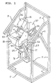
- FIG. 1 and 2 a preferred embodiment of a machine for cutting/grinding a lens blank L to a predetermined contour using a tool T is illustrated. While the contour to be cut/ground into the lens blank L is not necessarily spherical, the tool T is spherically shaped and must have a diameter that is not greater than twice the radius of the steepest curvature to be cut/ground into the lens blank L.
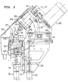
- the lens blank L is chucked to a lens spindle 11 and the tool T is mounted on a tool spindle 13.
- the lens spindle 11 has a vertical longitudinal central axis 15 and the tool spindle 13 has a longitudinal central axis 17. With the axes 15 and 17 aligned to intersect at the center 19 of the tool T, the angle 21 therebetween is in a range of approximately 125 to 145 degrees and preferably is 135 degrees, as shown.
- the lens spindle 11 is mounted for rotation about its longitudinal axis 15 in a lens spindle bearing assembly 23 which is in turn mounted on a Z carriage casting 25.
- the Z carriage casting 25 is slidably engaged on guide rails 27 which are mounted vertically on a Z base casting 29 which is in turn fixed to the machine frame F.
- the lens spindle 11 may rotate in the spindle bearing assembly 23 and reciprocate with the Z carriage casting 25 vertically on the guide rails 27.
- a motor 31 connected to the lower end of the lens spindle 11 provides the rotational drive for the lens spindle 11.
- Another motor 33 reciprocates the Z carriage casting 25 on the guide rails 27.
- the tool spindle 13 is mounted for rotation about its central axis 17 in a tool spindle bearing assembly 35 which is mounted on an X carriage casting 37.
- the X carriage casting 37 is in turn slidably mounted on guide rails 39 fixed horizontally on an X base casting 41 which is in turn fixed to the frame F of the machine.
- the tool spindle 13 may rotate in the tool spindle assembly 35 about its central axis 17 and reciprocate horizontally with the X carriage casting 37.
- a third motor 43 reciprocates the X carriage casting 37 on the guide rails 39 while a fourth motor 45 connected by a belt 47 to the upper end of the tool spindle 13 rotationally drives the tool spindle 13.
- all four motors 31, 33, 43 and 45 be DC brushless motors with encoders.
- the structure of the spindle bearing assemblies 23 and 35 and the structure connecting the motors 31, 33, 43 and 45 to the spindles 11 and 13 and to the Z and X carriage castings 25 and 27 need no further explanation for the purposes of the present disclosure, such structural configurations being well known in the art.
- the cutter/grinding area of the machine is enclosed in a chamber 51 which is connected to the frame F by brackets 53.
- a chuck assembly 55 on which the lens blank L will be mounted and which may be of any configuration known in the art is reciprocally and rotatively mounted on the upper end of the lens spindle 11.
- the chuck assembly 55 is situated in the lower portion of the chamber 51 with the lens spindle 11 extending through the bottom of the chamber 51.
- the tool T mounted on the tool spindle 13 is situated in the upper portion of the chamber 51 with the tool spindle 13 extending through a horizontal slot in an upper rear wall of the chamber 51.
- a user access opening 57 into the chamber 51 is covered by a sliding door 59 which is operated by an air cylinder 61.
- the opening 57 permits mounting and removal of the lens blank L on the chuck assembly 55 and replacement of the tool T.
- the frame F supporting the machine components preferably includes tubular members arranged to form a rectangular base, tubular upright members extending vertically from the corners of the base, a horizontal top member connecting the rear uprights and downwardly angled members extending from the rear uprights to their corresponding front uprights to provide a tilted work face for the machine. Additional tubular members are angled inwardly from the uprights to support the base castings 29 and 41.
- the machine includes a microprocessor 63 connected to a user interface including a keyboard 65 and a visual display 67 which will preferably be mounted in the slanted front face of the machine proximate the user access opening 57.
- the angular velocity of the tool spindle 13 is preferably constant, so the tool spindle drive motor 45 is connected directly to the microprocessor 63.
- the horizontal or X axis reciprocation of the tool spindle 13 and the angular velocity and vertical reciprocation of the lens spindle 11, however, are varied to control the contour to be cut/ground into the lens blank L. Therefore, the tool reciprocating motor 43 and the lens reciprocating and rotating motors 33 and 31 are connected to the microprocessor 63 through an I/O card 69.
- a second I/O card 71 may also be used to connect the microprocessor 63 to other equipment associated with the machine, such as swarf cutting equipment, a vacuum system, a water cooling system for glass grinding applications and pneumatic and hydraulic systems and the like (not shown).
- An outlet drain 73 is provided in the bottom of the chamber 51 for liquid coolant and waste material collected therewith to be ejected from the chamber 51.
- Microprocessor control of cutting/grinding machines for ophthalmic lenses is well known. It is, however, of significance to the present invention that the motions controlled by the microprocessor 63 are limited to a constant tool rotational speed, a horizontal or X axis reciprocation of the tool T, a nominal rotational speed of the lens spindle 11 and a vertical reciprocation of the lens spindle 11. The only nonrotational movement of the lens spindle 11 is its vertical reciprocation. The simplicity of this operation further permits the preferred use of passive I/O cards 69 and 71. Most importantly, the above structural configuration enables the use of a tool having a diameter approximating but not greater than twice the radius of the steepest curvature to be cut/ground into the lens blank L.
- the same machine can be used to cut/grind both plastic and glass lenses.
- Efficient glass grinding requires relative tool to lens blank surface speeds in a range of 5,000 feet per minute.
- the large diameter tool T permits tool angular velocities in a range of 8 to 10,000 rotations per minute and lens angular velocities in a range of 20 to 150 revolutions per minute.
- the angular velocity of the lens is negligible when considered in terms of the relative surface speed desired for grinding glass.
- a single machine using the above angular velocity parameters can therefore be used to cut plastic and glass.
- tools employing carbide inserts are preferable.
- a variety of other materials can be used in the tools.
- Diamond grinders will be used for grinding glass in a wet process.
- the machine can be switched to either a wet or dry process by the user via the microprocessor user interface.
Landscapes
- Engineering & Computer Science (AREA)
- Mechanical Engineering (AREA)
- Grinding And Polishing Of Tertiary Curved Surfaces And Surfaces With Complex Shapes (AREA)
Applications Claiming Priority (2)
| Application Number | Priority Date | Filing Date | Title |
|---|---|---|---|
| US182133 | 1998-10-29 | ||
| US09/182,133 US6106366A (en) | 1998-10-29 | 1998-10-29 | Lens grinder |
Publications (1)
| Publication Number | Publication Date |
|---|---|
| EP0997228A1 true EP0997228A1 (fr) | 2000-05-03 |
Family
ID=22667195
Family Applications (1)
| Application Number | Title | Priority Date | Filing Date |
|---|---|---|---|
| EP99308533A Withdrawn EP0997228A1 (fr) | 1998-10-29 | 1999-10-28 | Machine à meuler des verres à lunettes |
Country Status (3)
| Country | Link |
|---|---|
| US (1) | US6106366A (fr) |
| EP (1) | EP0997228A1 (fr) |
| JP (1) | JP2000153438A (fr) |
Cited By (4)
| Publication number | Priority date | Publication date | Assignee | Title |
|---|---|---|---|---|
| DE10106659A1 (de) * | 2001-02-12 | 2002-08-14 | Schneider Gmbh & Co Kg | Linsenpoliermaschine |
| EP1923686A3 (fr) * | 2006-11-17 | 2010-04-28 | Leica Mikrosysteme GmbH | Dispositif destiné au traitement d'un échantillon |
| US8113099B2 (en) | 2006-11-17 | 2012-02-14 | Leica Mikrosysteme Gmbh | Apparatus for processing a specimen |
| US10967475B2 (en) * | 2013-03-19 | 2021-04-06 | XI'AN JIAOTONG UNIVERSITY et al. | Polishing method for optical elements |
Families Citing this family (12)
| Publication number | Priority date | Publication date | Assignee | Title |
|---|---|---|---|---|
| JP4186286B2 (ja) * | 1998-12-11 | 2008-11-26 | 日本精工株式会社 | 位相合わせ装置 |
| DE10029967B4 (de) * | 2000-06-26 | 2006-08-03 | Satisloh Gmbh | Vorrichtung zur Bearbeitung von optischen Werkstücken |
| US20080286458A1 (en) * | 2005-03-09 | 2008-11-20 | The Walman Optical Company | Method and Apparatus for Coating Optics |
| JP4510710B2 (ja) * | 2005-07-05 | 2010-07-28 | 株式会社永田製作所 | 研摩装置 |
| US7591710B2 (en) * | 2005-12-30 | 2009-09-22 | Essilor International (Compagnie Generale D'optique) | Polishing machine comprising a work chamber and a platform |
| US7396275B2 (en) * | 2005-12-30 | 2008-07-08 | Essilor International (Compagnie General D'optique) | Polishing machine comprising sliding means transverse to the front face |
| FR2902683B1 (fr) * | 2006-06-22 | 2008-10-10 | Essilor Int | Procede et machine d'usinage pour objet optique. |
| US7373936B1 (en) * | 2006-12-06 | 2008-05-20 | Viateheslav Zagorouiko | Portable finishing apparatus for hard material |
| US20080230006A1 (en) * | 2007-03-19 | 2008-09-25 | The Walman Optical Company | Lens coating system |
| JP5080300B2 (ja) * | 2008-02-01 | 2012-11-21 | 有限会社コジマエンジニアリング | レンズ加工装置 |
| WO2010030798A2 (fr) * | 2008-09-10 | 2010-03-18 | The Walman Optical Company | Manipulation de lentille dans des systèmes de revêtement de lentille |
| WO2016070238A1 (fr) * | 2014-11-07 | 2016-05-12 | Dresden Optics Pty Ltd | Montures de lunettes et système |
Citations (4)
| Publication number | Priority date | Publication date | Assignee | Title |
|---|---|---|---|---|
| US3772832A (en) * | 1972-08-16 | 1973-11-20 | J Smith | Method of manufacturing contact lenses |
| EP0281754A2 (fr) * | 1987-03-09 | 1988-09-14 | Gerber Scientific Products, Inc. | Méthode et appareil pour la fabrication de lentilles pour lunettes d'après ordonnance |
| EP0453627A2 (fr) * | 1990-04-24 | 1991-10-30 | NATIONAL OPTRONICS, Inc. | Méthode et appareil pour la réalisation de lentilles en matière plastique |
| EP0844048A2 (fr) * | 1996-11-26 | 1998-05-27 | The Institute Of Physical & Chemical Research | Machine d'usinage de surface gauche |
Family Cites Families (7)
| Publication number | Priority date | Publication date | Assignee | Title |
|---|---|---|---|---|
| US1630253A (en) * | 1924-10-06 | 1927-05-31 | Continental Optical Corp | Machine for grinding lenses |
| US3353303A (en) * | 1964-11-13 | 1967-11-21 | Ait Ind Inc | Art of edging |
| FR2551382B1 (fr) * | 1983-09-02 | 1986-05-16 | Essilor Int | Procede et dispositif pour le surfacage d'une lentille optique |
| JPH02109671A (ja) * | 1988-10-20 | 1990-04-23 | Olympus Optical Co Ltd | レンズ研削機およびレンズ加工方法 |
| US5482495A (en) * | 1993-09-29 | 1996-01-09 | Matsushita Electric Industrial Co., Ltd. | Apparatus for polishing a spherical surface |
| EP0807491B1 (fr) * | 1996-05-17 | 1999-01-20 | Opto Tech GmbH | Support pour lentille optique et procédé pour polir des lentilles |
| EP0868972B1 (fr) * | 1997-03-26 | 1999-06-09 | Optotech Optikmaschinen GmbH | Procédé et dispositif pour l'usinage de lentilles optiques |
-
1998
- 1998-10-29 US US09/182,133 patent/US6106366A/en not_active Expired - Fee Related
-
1999
- 1999-10-28 EP EP99308533A patent/EP0997228A1/fr not_active Withdrawn
- 1999-10-28 JP JP11306604A patent/JP2000153438A/ja active Pending
Patent Citations (4)
| Publication number | Priority date | Publication date | Assignee | Title |
|---|---|---|---|---|
| US3772832A (en) * | 1972-08-16 | 1973-11-20 | J Smith | Method of manufacturing contact lenses |
| EP0281754A2 (fr) * | 1987-03-09 | 1988-09-14 | Gerber Scientific Products, Inc. | Méthode et appareil pour la fabrication de lentilles pour lunettes d'après ordonnance |
| EP0453627A2 (fr) * | 1990-04-24 | 1991-10-30 | NATIONAL OPTRONICS, Inc. | Méthode et appareil pour la réalisation de lentilles en matière plastique |
| EP0844048A2 (fr) * | 1996-11-26 | 1998-05-27 | The Institute Of Physical & Chemical Research | Machine d'usinage de surface gauche |
Cited By (5)
| Publication number | Priority date | Publication date | Assignee | Title |
|---|---|---|---|---|
| DE10106659A1 (de) * | 2001-02-12 | 2002-08-14 | Schneider Gmbh & Co Kg | Linsenpoliermaschine |
| EP1923686A3 (fr) * | 2006-11-17 | 2010-04-28 | Leica Mikrosysteme GmbH | Dispositif destiné au traitement d'un échantillon |
| US8113099B2 (en) | 2006-11-17 | 2012-02-14 | Leica Mikrosysteme Gmbh | Apparatus for processing a specimen |
| DE102006054617B4 (de) * | 2006-11-17 | 2017-06-01 | Leica Mikrosysteme Gmbh | Vorrichtung zum Bearbeiten einer Probe |
| US10967475B2 (en) * | 2013-03-19 | 2021-04-06 | XI'AN JIAOTONG UNIVERSITY et al. | Polishing method for optical elements |
Also Published As
| Publication number | Publication date |
|---|---|
| JP2000153438A (ja) | 2000-06-06 |
| US6106366A (en) | 2000-08-22 |
Similar Documents
| Publication | Publication Date | Title |
|---|---|---|
| US6106366A (en) | Lens grinder | |
| US6712671B2 (en) | Device for edge-machining of optical lenses | |
| US7597033B2 (en) | Machine for machining optical workpieces, in particular plastic spectacle lenses | |
| EP0655297B1 (fr) | Dispositif pour le polissage d'une lentille optique | |
| US7338347B2 (en) | Spectacle-lens edging machine | |
| KR19990082691A (ko) | 유리물품의가공마무리장치 | |
| KR100483738B1 (ko) | 연삭기 및 연삭방법 | |
| US6332386B1 (en) | Transmission mechanism for spindle head of five-axis machine tool | |
| EP1799383B1 (fr) | Outil de guidage multi-lame, dresseuse avec outil de guidage multi-lame et technique de dressage des bords de verres de lunette | |
| EP0043233B1 (fr) | Appareil de doucissage et de polissage | |
| CA2079148C (fr) | Tour pour la fabrication de produits ophtalmiques a partir d'ebauches et mode de mise en oeuvre | |
| CN213889594U (zh) | 数控砂轮修整装置 | |
| JP5456550B2 (ja) | レンズ加工装置 | |
| JPH05329762A (ja) | 曲面研磨方法および装置 | |
| US5335560A (en) | Table-top grinder power transmission mechanism | |
| JPH01127261A (ja) | トーリック面の研面研磨装置 | |
| CN214642583U (zh) | 一种高精准度磨床 | |
| JPS597550A (ja) | 曲面研削加工機械 | |
| CN212043971U (zh) | 圆形镜片抛光系统 | |
| US5085007A (en) | Toric lens fining apparatus | |
| CN109366286B (zh) | 一种具有倾斜倒角模的自动倒边机 | |
| US4271636A (en) | Lens generating apparatus | |
| US3838542A (en) | Lens polishing machine | |
| CN221390388U (zh) | 一种多角度磨削的磨床结构 | |
| JP4183892B2 (ja) | 研磨工具およびこの研磨工具を用いた研磨装置 |
Legal Events
| Date | Code | Title | Description |
|---|---|---|---|
| PUAI | Public reference made under article 153(3) epc to a published international application that has entered the european phase |
Free format text: ORIGINAL CODE: 0009012 |
|
| AK | Designated contracting states |
Kind code of ref document: A1 Designated state(s): DE FR GB |
|
| AX | Request for extension of the european patent |
Free format text: AL;LT;LV;MK;RO;SI |
|
| 17P | Request for examination filed |
Effective date: 20001102 |
|
| AKX | Designation fees paid |
Free format text: DE FR GB |
|
| 17Q | First examination report despatched |
Effective date: 20030114 |
|
| STAA | Information on the status of an ep patent application or granted ep patent |
Free format text: STATUS: THE APPLICATION IS DEEMED TO BE WITHDRAWN |
|
| 18D | Application deemed to be withdrawn |
Effective date: 20030527 |