EP0996385B1 - Systeme pour poser des plaques d'osteosynthese squelettiques - Google Patents
Systeme pour poser des plaques d'osteosynthese squelettiques Download PDFInfo
- Publication number
- EP0996385B1 EP0996385B1 EP98906158A EP98906158A EP0996385B1 EP 0996385 B1 EP0996385 B1 EP 0996385B1 EP 98906158 A EP98906158 A EP 98906158A EP 98906158 A EP98906158 A EP 98906158A EP 0996385 B1 EP0996385 B1 EP 0996385B1
- Authority
- EP
- European Patent Office
- Prior art keywords
- plate
- bone
- bone screw
- locking
- screw
- Prior art date
- Legal status (The legal status is an assumption and is not a legal conclusion. Google has not performed a legal analysis and makes no representation as to the accuracy of the status listed.)
- Expired - Lifetime
Links
Images


Classifications
-
- A—HUMAN NECESSITIES
- A61—MEDICAL OR VETERINARY SCIENCE; HYGIENE
- A61B—DIAGNOSIS; SURGERY; IDENTIFICATION
- A61B17/00—Surgical instruments, devices or methods, e.g. tourniquets
- A61B17/16—Bone cutting, breaking or removal means other than saws, e.g. Osteoclasts; Drills or chisels for bones; Trepans
- A61B17/1604—Chisels; Rongeurs; Punches; Stamps
-
- A—HUMAN NECESSITIES
- A61—MEDICAL OR VETERINARY SCIENCE; HYGIENE
- A61B—DIAGNOSIS; SURGERY; IDENTIFICATION
- A61B17/00—Surgical instruments, devices or methods, e.g. tourniquets
- A61B17/56—Surgical instruments or methods for treatment of bones or joints; Devices specially adapted therefor
- A61B17/58—Surgical instruments or methods for treatment of bones or joints; Devices specially adapted therefor for osteosynthesis, e.g. bone plates, screws, setting implements or the like
- A61B17/68—Internal fixation devices, including fasteners and spinal fixators, even if a part thereof projects from the skin
- A61B17/80—Cortical plates, i.e. bone plates; Instruments for holding or positioning cortical plates, or for compressing bones attached to cortical plates
- A61B17/8052—Cortical plates, i.e. bone plates; Instruments for holding or positioning cortical plates, or for compressing bones attached to cortical plates immobilised relative to screws by interlocking form of the heads and plate holes, e.g. conical or threaded
-
- A—HUMAN NECESSITIES
- A61—MEDICAL OR VETERINARY SCIENCE; HYGIENE
- A61B—DIAGNOSIS; SURGERY; IDENTIFICATION
- A61B17/00—Surgical instruments, devices or methods, e.g. tourniquets
- A61B17/16—Bone cutting, breaking or removal means other than saws, e.g. Osteoclasts; Drills or chisels for bones; Trepans
- A61B17/17—Guides or aligning means for drills, mills, pins or wires
- A61B17/1739—Guides or aligning means for drills, mills, pins or wires specially adapted for particular parts of the body
- A61B17/1757—Guides or aligning means for drills, mills, pins or wires specially adapted for particular parts of the body for the spine
-
- A—HUMAN NECESSITIES
- A61—MEDICAL OR VETERINARY SCIENCE; HYGIENE
- A61B—DIAGNOSIS; SURGERY; IDENTIFICATION
- A61B17/00—Surgical instruments, devices or methods, e.g. tourniquets
- A61B17/56—Surgical instruments or methods for treatment of bones or joints; Devices specially adapted therefor
- A61B17/58—Surgical instruments or methods for treatment of bones or joints; Devices specially adapted therefor for osteosynthesis, e.g. bone plates, screws, setting implements or the like
- A61B17/68—Internal fixation devices, including fasteners and spinal fixators, even if a part thereof projects from the skin
- A61B17/70—Spinal positioners or stabilisers ; Bone stabilisers comprising fluid filler in an implant
- A61B17/7059—Cortical plates
-
- A—HUMAN NECESSITIES
- A61—MEDICAL OR VETERINARY SCIENCE; HYGIENE
- A61B—DIAGNOSIS; SURGERY; IDENTIFICATION
- A61B17/00—Surgical instruments, devices or methods, e.g. tourniquets
- A61B17/56—Surgical instruments or methods for treatment of bones or joints; Devices specially adapted therefor
- A61B17/58—Surgical instruments or methods for treatment of bones or joints; Devices specially adapted therefor for osteosynthesis, e.g. bone plates, screws, setting implements or the like
- A61B17/68—Internal fixation devices, including fasteners and spinal fixators, even if a part thereof projects from the skin
- A61B17/80—Cortical plates, i.e. bone plates; Instruments for holding or positioning cortical plates, or for compressing bones attached to cortical plates
- A61B17/8004—Cortical plates, i.e. bone plates; Instruments for holding or positioning cortical plates, or for compressing bones attached to cortical plates with means for distracting or compressing the bone or bones
- A61B17/8019—Cortical plates, i.e. bone plates; Instruments for holding or positioning cortical plates, or for compressing bones attached to cortical plates with means for distracting or compressing the bone or bones where the means are a separate tool rather than being part of the plate
-
- A—HUMAN NECESSITIES
- A61—MEDICAL OR VETERINARY SCIENCE; HYGIENE
- A61B—DIAGNOSIS; SURGERY; IDENTIFICATION
- A61B17/00—Surgical instruments, devices or methods, e.g. tourniquets
- A61B17/56—Surgical instruments or methods for treatment of bones or joints; Devices specially adapted therefor
- A61B17/58—Surgical instruments or methods for treatment of bones or joints; Devices specially adapted therefor for osteosynthesis, e.g. bone plates, screws, setting implements or the like
- A61B17/68—Internal fixation devices, including fasteners and spinal fixators, even if a part thereof projects from the skin
- A61B17/80—Cortical plates, i.e. bone plates; Instruments for holding or positioning cortical plates, or for compressing bones attached to cortical plates
- A61B17/8033—Cortical plates, i.e. bone plates; Instruments for holding or positioning cortical plates, or for compressing bones attached to cortical plates having indirect contact with screw heads, or having contact with screw heads maintained with the aid of additional components, e.g. nuts, wedges or head covers
- A61B17/8042—Cortical plates, i.e. bone plates; Instruments for holding or positioning cortical plates, or for compressing bones attached to cortical plates having indirect contact with screw heads, or having contact with screw heads maintained with the aid of additional components, e.g. nuts, wedges or head covers the additional component being a cover over the screw head
-
- A—HUMAN NECESSITIES
- A61—MEDICAL OR VETERINARY SCIENCE; HYGIENE
- A61B—DIAGNOSIS; SURGERY; IDENTIFICATION
- A61B17/00—Surgical instruments, devices or methods, e.g. tourniquets
- A61B17/56—Surgical instruments or methods for treatment of bones or joints; Devices specially adapted therefor
- A61B17/58—Surgical instruments or methods for treatment of bones or joints; Devices specially adapted therefor for osteosynthesis, e.g. bone plates, screws, setting implements or the like
- A61B17/68—Internal fixation devices, including fasteners and spinal fixators, even if a part thereof projects from the skin
- A61B17/84—Fasteners therefor or fasteners being internal fixation devices
- A61B17/86—Pins or screws or threaded wires; nuts therefor
- A61B17/8625—Shanks, i.e. parts contacting bone tissue
- A61B17/863—Shanks, i.e. parts contacting bone tissue with thread interrupted or changing its form along shank, other than constant taper
-
- A—HUMAN NECESSITIES
- A61—MEDICAL OR VETERINARY SCIENCE; HYGIENE
- A61B—DIAGNOSIS; SURGERY; IDENTIFICATION
- A61B17/00—Surgical instruments, devices or methods, e.g. tourniquets
- A61B17/16—Bone cutting, breaking or removal means other than saws, e.g. Osteoclasts; Drills or chisels for bones; Trepans
- A61B17/1662—Bone cutting, breaking or removal means other than saws, e.g. Osteoclasts; Drills or chisels for bones; Trepans for particular parts of the body
- A61B17/1671—Bone cutting, breaking or removal means other than saws, e.g. Osteoclasts; Drills or chisels for bones; Trepans for particular parts of the body for the spine
-
- A—HUMAN NECESSITIES
- A61—MEDICAL OR VETERINARY SCIENCE; HYGIENE
- A61B—DIAGNOSIS; SURGERY; IDENTIFICATION
- A61B17/00—Surgical instruments, devices or methods, e.g. tourniquets
- A61B17/16—Bone cutting, breaking or removal means other than saws, e.g. Osteoclasts; Drills or chisels for bones; Trepans
- A61B17/17—Guides or aligning means for drills, mills, pins or wires
- A61B17/1728—Guides or aligning means for drills, mills, pins or wires for holes for bone plates or plate screws
-
- A—HUMAN NECESSITIES
- A61—MEDICAL OR VETERINARY SCIENCE; HYGIENE
- A61B—DIAGNOSIS; SURGERY; IDENTIFICATION
- A61B17/00—Surgical instruments, devices or methods, e.g. tourniquets
- A61B17/56—Surgical instruments or methods for treatment of bones or joints; Devices specially adapted therefor
- A61B17/58—Surgical instruments or methods for treatment of bones or joints; Devices specially adapted therefor for osteosynthesis, e.g. bone plates, screws, setting implements or the like
- A61B17/68—Internal fixation devices, including fasteners and spinal fixators, even if a part thereof projects from the skin
- A61B17/80—Cortical plates, i.e. bone plates; Instruments for holding or positioning cortical plates, or for compressing bones attached to cortical plates
- A61B17/8033—Cortical plates, i.e. bone plates; Instruments for holding or positioning cortical plates, or for compressing bones attached to cortical plates having indirect contact with screw heads, or having contact with screw heads maintained with the aid of additional components, e.g. nuts, wedges or head covers
-
- A—HUMAN NECESSITIES
- A61—MEDICAL OR VETERINARY SCIENCE; HYGIENE
- A61B—DIAGNOSIS; SURGERY; IDENTIFICATION
- A61B17/00—Surgical instruments, devices or methods, e.g. tourniquets
- A61B17/56—Surgical instruments or methods for treatment of bones or joints; Devices specially adapted therefor
- A61B17/58—Surgical instruments or methods for treatment of bones or joints; Devices specially adapted therefor for osteosynthesis, e.g. bone plates, screws, setting implements or the like
- A61B17/68—Internal fixation devices, including fasteners and spinal fixators, even if a part thereof projects from the skin
- A61B17/80—Cortical plates, i.e. bone plates; Instruments for holding or positioning cortical plates, or for compressing bones attached to cortical plates
- A61B17/8085—Cortical plates, i.e. bone plates; Instruments for holding or positioning cortical plates, or for compressing bones attached to cortical plates with pliable or malleable elements or having a mesh-like structure, e.g. small strips
-
- A—HUMAN NECESSITIES
- A61—MEDICAL OR VETERINARY SCIENCE; HYGIENE
- A61B—DIAGNOSIS; SURGERY; IDENTIFICATION
- A61B17/00—Surgical instruments, devices or methods, e.g. tourniquets
- A61B17/56—Surgical instruments or methods for treatment of bones or joints; Devices specially adapted therefor
- A61B17/58—Surgical instruments or methods for treatment of bones or joints; Devices specially adapted therefor for osteosynthesis, e.g. bone plates, screws, setting implements or the like
- A61B17/68—Internal fixation devices, including fasteners and spinal fixators, even if a part thereof projects from the skin
- A61B17/84—Fasteners therefor or fasteners being internal fixation devices
- A61B17/86—Pins or screws or threaded wires; nuts therefor
- A61B17/8605—Heads, i.e. proximal ends projecting from bone
- A61B17/861—Heads, i.e. proximal ends projecting from bone specially shaped for gripping driver
-
- A—HUMAN NECESSITIES
- A61—MEDICAL OR VETERINARY SCIENCE; HYGIENE
- A61B—DIAGNOSIS; SURGERY; IDENTIFICATION
- A61B17/00—Surgical instruments, devices or methods, e.g. tourniquets
- A61B17/56—Surgical instruments or methods for treatment of bones or joints; Devices specially adapted therefor
- A61B17/58—Surgical instruments or methods for treatment of bones or joints; Devices specially adapted therefor for osteosynthesis, e.g. bone plates, screws, setting implements or the like
- A61B17/68—Internal fixation devices, including fasteners and spinal fixators, even if a part thereof projects from the skin
- A61B17/84—Fasteners therefor or fasteners being internal fixation devices
- A61B17/86—Pins or screws or threaded wires; nuts therefor
- A61B17/8625—Shanks, i.e. parts contacting bone tissue
-
- A—HUMAN NECESSITIES
- A61—MEDICAL OR VETERINARY SCIENCE; HYGIENE
- A61B—DIAGNOSIS; SURGERY; IDENTIFICATION
- A61B17/00—Surgical instruments, devices or methods, e.g. tourniquets
- A61B17/56—Surgical instruments or methods for treatment of bones or joints; Devices specially adapted therefor
- A61B17/58—Surgical instruments or methods for treatment of bones or joints; Devices specially adapted therefor for osteosynthesis, e.g. bone plates, screws, setting implements or the like
- A61B17/68—Internal fixation devices, including fasteners and spinal fixators, even if a part thereof projects from the skin
- A61B17/84—Fasteners therefor or fasteners being internal fixation devices
- A61B17/86—Pins or screws or threaded wires; nuts therefor
- A61B17/8695—Washers
-
- A—HUMAN NECESSITIES
- A61—MEDICAL OR VETERINARY SCIENCE; HYGIENE
- A61B—DIAGNOSIS; SURGERY; IDENTIFICATION
- A61B17/00—Surgical instruments, devices or methods, e.g. tourniquets
- A61B17/56—Surgical instruments or methods for treatment of bones or joints; Devices specially adapted therefor
- A61B17/58—Surgical instruments or methods for treatment of bones or joints; Devices specially adapted therefor for osteosynthesis, e.g. bone plates, screws, setting implements or the like
- A61B17/88—Osteosynthesis instruments; Methods or means for implanting or extracting internal or external fixation devices
- A61B17/8875—Screwdrivers, spanners or wrenches
-
- A—HUMAN NECESSITIES
- A61—MEDICAL OR VETERINARY SCIENCE; HYGIENE
- A61B—DIAGNOSIS; SURGERY; IDENTIFICATION
- A61B17/00—Surgical instruments, devices or methods, e.g. tourniquets
- A61B2017/0046—Surgical instruments, devices or methods, e.g. tourniquets with a releasable handle; with handle and operating part separable
-
- A—HUMAN NECESSITIES
- A61—MEDICAL OR VETERINARY SCIENCE; HYGIENE
- A61B—DIAGNOSIS; SURGERY; IDENTIFICATION
- A61B17/00—Surgical instruments, devices or methods, e.g. tourniquets
- A61B17/56—Surgical instruments or methods for treatment of bones or joints; Devices specially adapted therefor
- A61B17/58—Surgical instruments or methods for treatment of bones or joints; Devices specially adapted therefor for osteosynthesis, e.g. bone plates, screws, setting implements or the like
- A61B17/68—Internal fixation devices, including fasteners and spinal fixators, even if a part thereof projects from the skin
- A61B17/84—Fasteners therefor or fasteners being internal fixation devices
- A61B17/86—Pins or screws or threaded wires; nuts therefor
- A61B2017/8655—Pins or screws or threaded wires; nuts therefor with special features for locking in the bone
-
- A—HUMAN NECESSITIES
- A61—MEDICAL OR VETERINARY SCIENCE; HYGIENE
- A61F—FILTERS IMPLANTABLE INTO BLOOD VESSELS; PROSTHESES; DEVICES PROVIDING PATENCY TO, OR PREVENTING COLLAPSING OF, TUBULAR STRUCTURES OF THE BODY, e.g. STENTS; ORTHOPAEDIC, NURSING OR CONTRACEPTIVE DEVICES; FOMENTATION; TREATMENT OR PROTECTION OF EYES OR EARS; BANDAGES, DRESSINGS OR ABSORBENT PADS; FIRST-AID KITS
- A61F2/00—Filters implantable into blood vessels; Prostheses, i.e. artificial substitutes or replacements for parts of the body; Appliances for connecting them with the body; Devices providing patency to, or preventing collapsing of, tubular structures of the body, e.g. stents
- A61F2/0077—Special surfaces of prostheses, e.g. for improving ingrowth
-
- Y—GENERAL TAGGING OF NEW TECHNOLOGICAL DEVELOPMENTS; GENERAL TAGGING OF CROSS-SECTIONAL TECHNOLOGIES SPANNING OVER SEVERAL SECTIONS OF THE IPC; TECHNICAL SUBJECTS COVERED BY FORMER USPC CROSS-REFERENCE ART COLLECTIONS [XRACs] AND DIGESTS
- Y10—TECHNICAL SUBJECTS COVERED BY FORMER USPC
- Y10S—TECHNICAL SUBJECTS COVERED BY FORMER USPC CROSS-REFERENCE ART COLLECTIONS [XRACs] AND DIGESTS
- Y10S606/00—Surgery
- Y10S606/907—Composed of particular material or coated
- Y10S606/909—Bone
Definitions
- the invention relates to a skeletal plating system according to the preamble of claim 1. Accordingly, the present invention relates generally to skeletal plate systems for aligning and maintaining bone portions of the same bone or of different bones in a selected spatial relationship for healing or fusion of the bone portions, respectively.
- a system of the above mentioned type is known, e.g., from US 5, 364, 399 .
- Another plate of this type is known, e.g., from US 4, 488, 543 .
- plating systems for joining portions of a broken bone, or for fusion of portions of separate bones.
- Such systems are composed essentially of plates and screws for aligning and holding the bone portions in a desired position relative to one another.
- Plating systems have usefulness in the spine, and have general skeletal use on the flat bones, such as the scapula and the pelvis by way of example, and for use on tubular bones, such as the humerus, ulna, radius, femur, and tibia by way of example.
- Plates are usually provided to the surgeon for use in sets having a range of sizes so as to provide for such features as biological variability in size, the numbers of segments to be joined, and the length of the portions of bone to be joined.
- a plating system for use on the anterior cervical spine and for joining from two to five vertebrae to comprise of from forty to sixty plates. This requires manufacturers to make a large number of different plates, resulting in increased manufacturing costs and inventory costs and increased costs for hospitals to stock large numbers of plates.
- the ability to provide to a patient the best care could be compromised.
- the invention provides a skeletal plating system having the features of claims 1. Further embodiments of the invention are described in the dependent claims.
- a skeletal plating system comprising a plate, that has a lower surface that is convex curved along a substantial portion of the longitudinal axis of the plate, bone screws, and locks for locking the bone screws to the plate for skeletal use.
- the plating system of a first embodiment of the, present invention comprises a general use skeletal plate having a bottom surface for placement against bone portions, wherein a substantial portion of the bottom surface of the plate is convex along the longitudinal axis of the plate. It is appreciated that a lesser portion of the lower surface of the plate may be otherwise shaped.
- the plate of the present invention has a plurality of bone screw receiving holes which extend through the plate, from the upper surface to the lower surface.
- the plate and its component parts may be made of any implant quality material suitable for this purpose and suitable for use in the human body, such as, but not limited to, titanium or its alloys.
- the plate and/or the associated components may be made of a bioresorbable material and may comprise or be coated at least in part with fusion promoting chemical substances, such as bone morphogenetic proteins and the like.
- Bone screws are each insertable into a respective bone screw receiving hole for attaching the plate to bone.
- a locking element preferably, but not necessarily, in the form of a screw, is engageable in the locking screw hole of the plate and has a head formed to lock at least two of the bone screws to the plate.
- the locking elements are pre-installed prior to use by the surgeon in a manner so as to not impede installation of the bone screws into the bone screw receiving holes.
- the locking elements can be in many forms to achieve their intended purpose, such as, but not limited to, screws, threaded caps, rivets, set screws, projecting elements, and the like.
- a plate provides for the crossing over of the shafts of at least a pair of bone screws within a bone portion.
- a crossed orientation of the screws within the bone provides a more secure engagement of the plate to the bone to which it is to be applied because longer screws may be used and because an area of bone is wedged and trapped between the screws as compared to plates which do not allow paired screws to cross.
- the use of further screws crossed and/or not crossed in combination with the crossed screw pair can be utilized to trap a still larger section of bone.
- the plate of the present invention may have multiple bone screw receiving bores (with fixed central longitudinal axes) in which the bores are oriented in a staggered configuration, such that the center points of each of the paired bone screw hole receiving bores are on different transverse lines to permit at least a pair of bone screws to be inserted in a crossed-over configuration within a bone portion.
- the screw bores have defined longitudinal axes in the transverse plane of the plate though the screws may be capable of a variation in positioning as will subsequently be described.
- the included angle formed by the shafts of the crossed screws is between 25 to 90 degrees.
- the paired screws are staggered, but are still alignable within the same vertebra so as to be diagonally crossed within that same vertebra and preferably crossed within the posterior two thirds of the vertebral body.
- a segmentable plating system is disclosed combined with the multiple lock plating system.
- the segmentable plating system provides a single plate, or a limited set of plates, for aligning and maintaining bone portions in selected spatial relationship in which the plates are manufactured so as to be strong in use, but separable into shorter lengths by the surgeon as needed, thereby eliminating the need to stock a multitude of plate lengths.
- an embodiment of the segmentable plating system of the present invention comprises a plate that is capable of spanning multiple segments of a cervical spine and has predetermined separation zones.
- the separation zones may be positioned in a segmentable plate such that when a portion of the segmentable plate would be applied to the vertebrae, the remaining separation zones in the plate, if any, would be supported by an underlying vertebrae.
- the surgeon would determine the appropriate plate length needed and if the length needed was less than the length of the provided plate, the surgeon would remove the unneeded portion of the plate at the appropriate separation zone.
- this procedure may be easily performed when the plate is made of titanium or one of its alloys, as the properties of titanium are such that when the plate is bent and then returned to its original position, a clean separation is made at the bend.
- the parts of the segmentable plates that are being separated can be held to either side of the separation zone to ensure that a precise separation is effected.
- the separation zones of the segmentable plate may comprise of the plate being scored along its upper, lower, or both upper and lower surfaces. The depth of such scores being dependent on the thickness of the plate, and being sufficient to create surface notchings and a path of least resistance for the plate separation, and yet of limited depth and shape, so as to not weaken the plate so as to render it less than sufficiently strong for its intended use.
- each segmentable plate having generally a similar length for example sufficient to span five vertebrae (a length of from 80 to 120 mm), and each having different spacings between pairs of bone screw holes could comprise a complete set of plates allowing a surgeon to have all lengths and hole spacings needed to fuse from two to five vertebrae. While the described plates may be separable into a multitude of usable portions, because of regulatory issues involving the identification of each implant with a distinct and singular implant identification number for tracking purposes it may be desirable to configure the plates of the present invention such that each plate will yield only one usable portion.
- the segmentable plating system of the present invention also has application in reconstructive surgery. For example, during repair of a broken eye socket, the segmentable plating system of the present invention can be used to align and maintain the broken bone portions in correct spatial relationship.
- the curved characteristic of an eye socket would require the plate used to repair the socket to match the curvature.
- the correct length of the segmentable plate can also be easily obtained by the surgeon as already described.
- the ability to separate a plate into segments also provides significant advantages in the manufacturing process.
- a process commonly used to produce plates The investment casting cost of material is minor relative to the labor involved in the casting process for the production of each plate regardless of size. It is far more economical to cast one eight inch long plate, which is later separable into four two inch long plates, than to make four two inch castings. If machining is included in production, as from bare stock or stamping or casting, that work can be automated, but the placing of the piece into the machine and securing it (fixturing) generally requires hands on attention, is time consuming, and is a potential manufacturing bottleneck.
- An eight inch long plate yielding four two inch plates potentially separable at the end by the machine doing the machining may be fixtured only once.
- the prior art method of manufacturing would require each of the four two inch long plates to be fixtured separately, one at a time. Therefore, the manufacturer can cast one long segmentable plate which can then be separated in the later manufacturing stages to yield multiple plates at an overall lower cost.
- the plate were in the alternative to be manufactured by machining from solid stock, great labor could be saved by fixturing and securing a single long plate that is later separable into multiple plates rather than having to fixture and secure each of those plates individually.
- three types of combination screw-lock-plate systems are taught, each capable of intersegmentable shortening and/or compression.
- Each of the taught systems is designed to counteract and compensate for the lack of contact between bone portions to be joined that may occur as a result of creeping substitution described above.
- the present invention will allow the vertebrae to move toward an interposed bone graft, and each other if necessary, instead of keeping the vertebrae apart during the occurrence of the resorption phase of the creeping substitution process.
- the present invention may allow for the preservation and/or enhancement of lordosis while otherwise restricting the motion of the bone screws relative to the plate.
- Screw-plate-lock systems which are themselves combinable with one another, are as follows: (1) Passive Dynamic; (2) Self-Compressing; and (3) Active Dynamic and are described below.
- locked means the screws are locked to the plate and can not backout.
- dynamic means the screw is capable of movement even though it is locked within the plate to allow bone portions to move closer together.
- passive means motion of the screw relative to the plate is allowed, but not caused.
- the passive dynamic system allows a bone screw to move relative to the plate even after being locked to the plate when a force is presented against the screw.
- This system does not cause screw movement, but only allows for movement of the screw to occur and thus is a "passive" system.
- motion of the screw relative to the plate is confined to but one direction, that direction permitting bone portions to move closer to one another along the longitudinal axis of the plate.
- a plate having a screw hole passing through the top and bottom surfaces of the plate for receiving a bone screw may have a round opening at the top of the plate and may have a bottom opening that is oblong-shaped with a length greater than the diameter of a bone screw shaft locatable the screw hole when in use.
- the head of the bone screw is secured to the plate against backing out and generally against significant linear motion with a locking element, while the shaft of the bone screw is capable of angular motion relative to the plate.
- the oblong-shaped bottom opening of the screw hole allows the shaft of the bone screw to travel relative to the plate while the bone screw head rotates. The movement of the screw is greatest at the distal end of the screw, allowing for differential shortening of the bone portions being joined. For example, if such a plating system is applied to the anterior aspect of the cervical spine, lordosis (a convex curvature forward of the aligned vertebrae of the neck when viewed from the side) is enhanced when said passive movement occurs.
- a purpose of the self-compressing system is to provide a fixed and locked angle of the bone screw relative to the plate for providing compression of bone portions to be joined, such as for example the cervical vertebrae adjacent a disc space, with movement of the bone screw as it is seated to the plate, producing compression and lordosis.
- the screws are only allowed to move in one direction, that being the direction that would bring bone portions to be joined closer together by angular motion, rather than to produce translational motion of a screw as a whole, without angular change.
- This induction of a compressive load across bone portions to be joined or fused induces bone growth and when bone resorption occurs at the interface of the bone portions to be joined, those bone portions are urged to move closer together, thus avoiding the formation of a gap so as to mitigate against non-union or pseudoarthrosis.
- the self-compressing system may comprise a plate having a bone screw receiving hole passing through the top and bottom surfaces of the plate with a top opening that is round and has a rounded seat.
- the bone screw receiving hole has bottom opening that has a central longitudinal axis that is offset from the central longitudinal axis of the top opening.
- the bone screw may have a partially rounded head which fits within the upper portion of the bone screw opening and permits movement of the screw head within the top opening in order to provide the appropriate angle for the bone screw shaft with respect to the plate as the bone screw shaft passes through the bottom opening.
- a pre-load force is applied to a bone screw such that while the screw may undergo no added motion initially, there is a selective force applied to the screwhead and the screw is capable of motion in only one direction, such that should resorption occur at the interfaces of the bone portions to be joined then the screw is not only free to move in that, and only that direction, but is also urged to do so as it moves to relieve the preload force.
- a plating system may utilize bone screw holes that have a lower surface opening that is oblong and extends from the center aligned to the longitudinal axis of the bone screw receiving bore in a direction for which screw motion is desired.
- a loading means such as a Bellville washer, lock washer, or other springing means is employed to bear upon the screw head when the screw is locked within the plate from backing out. Such a system urges the bone portions together over time as resorption permits.
- the Belville-type washer can have a tab which fits into a recess formed within the top opening of the screw hole in order to facilitate proper orientation of the washer or the washer or spring means can be other than round so as to be directionally orientable when placed within the top opening of the screw hole.
- a further object of the invention is to provide plates which are textured or otherwise treated to promote bone growth beneath the plate.
- Yet another object of the invention is to provide a system in which the bone screws and locking mechanisms, when fully installed, have a low profile.
- It is another object of the present invention is to provide means for preventing distraction pseudoarthrosis of the anterior cervical spine, while providing.for cervical lordosis.
- a plurality of bone screws are locked to a plate with a pre-installed locking element.
- This is referred to as the multiple locking plate system.
- the multiple locking plates will be described, then the locking elements for locking the bone screws to the plate, and then novel bone screws for use with the plates of the present invention.
- a single locking element locks a single bone screw to the plate and is referred to as the single lock system.
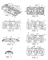
- Plate 2 has a generally elongated form whose outline is generally rectangular. It is recognized that other shapes for plate 2 may be employed. Plate 2 has a bottom surface 27 for placement against bone portions, wherein a substantial portion of bottom surface 27 is either flat and/or convex along the longitudinal axis of the plate. Plate 2 is for general skeletal use other than in the anterior cervical spine.
- plate 2 is provided with three locking screw holes 12, each of which in the preferred embodiment is internally threaded 3, and each of which is surrounded by a shallow countersunk region 14.
- bone screws are inserted in the bone screw receiving holes and a single locking element associated with each of the locking screw holes 12 locks a number of bone screws 30 in position at one time.
- the locking element may be pre-installed to the plate.
- each end locking element 20 will lock three bone screws 30 in place, while locking screw 21 in central locking hole 12 locks two bone screws 30 in place.
- central locking element 25 can also be configured so that four bone screws 30 are locked at one time.
- Plate 2 may have a thickness appropriate for the strength required for the bone or bones to which it is to be applied and generally in a range from 2 to 8 mm is preferred.
- bottom surface 27 of plate 2 preferably has a porous, and/or textured surface and may be coated with, impregnated with, or comprise of fusion promoting substances (such as bone morphogenetic proteins) so as to encourage the growth of bone along the underside of plate 2 from bone portion to bone portion.
- the textured bottom surface 27 also provides a medium for retaining fusion promoting substances with which the bottom surface 27 layer can be impregnated prior to installation.
- the bottom surface 27 of plate 2 may be given the desired porous textured form by rough blasting or any other conventional technology, such as etching, plasma spraying, sintering, and casting for example.
- the bottom surface 27 is formed to have a porosity or pore size in the order of 50-500 microns, and preferably 100-300 microns.
- Bone growth promoting substances with which the porous, textured bottom surface 27 can be impregnated include, but are not limited to, bone morphogenetic proteins, hydroxyapatite, or hydroxyapatite tricalcium phosphate.
- the plate 2 may comprise of at least in part a resorbable material which can further be impregnated with a bone growth material so that as the resorbable material is resorbed by the body of the patient, the bone growth material is released, thus acting as a time release mechanism.
- At least one end of plate 2 may have a recess 18 that can cooperate with a compression apparatus.
- FIG. 6 is a top plan view of plate 2 of FIG. 1 with locking elements 20, 21 inserted.
- the locking elements are in the form of screws that cooperate with the threaded interior 3 of the locking holes 12.
- Each of these locking elements 20, 21 is shown in its initial open orientation, where the orientation of the cutouts 22 in the head 23 of each locking element 20, 21 is oriented so as to permit introduction of bone screws 30 into adjacent bone screw receiving holes 6,8 without interference by the head 23 of the locking element 20, 21.
- FIG. 8 is a top view of another embodiment of plate 2 of FIGS. 1-5, and is generally referred to as plate 120.
- Plate 120 is provided with a longitudinally extending elongated slot 122 along its longitudinal axis which is superimposed on the middle locking hole 12.
- Elongated slot 122 allows additional relative movement between plate 120 and a compression post 54 associated with a compression tool during a compression procedure.
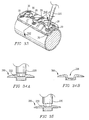
- FIGS. 14 and 15 an alternative embodiment of a multiple locking plate referred to by the number 70 is shown.
- plate 70 rather than the threaded locking hole 12, a central opening 200 for receiving a removable rivet 202, of the type shown in FIGS. 17-20, is provided.
- FIG. 15 is a bottom view of the plate 70 shown in FIG. 14. The contour of plate 70 is the same as that of plate 2 shown in FIGS. 1-5.
- the rivet 202 is removable and fits within the unthreaded opening 200, comparable to the locking hole 12 and slot 122 described above.
- Other embodiments may employ a rivet that is not removable, but is manufactured as part of plate 70 as would be used in the end locking holes 19 of FIGS. 14 and 15.
- FIG. 22 another alternative embodiment of a multiple locking plate is shown and is generally referred to by the number 230.
- the plate 230 uses threaded caps, such as cap 300 shown in FIGS. 9 and 23, for a locking element or preferably one with cut outs as described herein having an appearance in a top view such as the locking screw element in FIGS. 10-11, for example.
- the central locking hole 602 has an elongated slot 234 for providing an increased compression capability, if desired.
- FIG. 10 is a top plan view illustrating the head 23 of the central locking element 25 shown in FIG. 7.
- the shaft 46 of locking element 25 is threaded 47 to mate with the threading 3 within the associated locking hole 12 of plate 2.
- each segment 49 on each side of cutouts 22 of the locking element 21 has a bearing surface 48 formed at the lower surface of locking element head 23.
- the locking element head 23 can be provided with two slits 42 for providing flexibility to the locking element head 23 to assist in the locking element's ability to ride over the top of the bone screw head 32 during the locking action when the locking element is rotated.
- a ramp or wedge shaped surface 44 may be used to increase the force applied to the bone screw head 32.
- cam design when locked the leading end of the ramped portion 44 of locking element 21 would be lower than the prominence of the bone screw head 32 so that more force is needed to lift the locking element 21 and untighten it than is needed for the locking element 21 to remain tight and locked.
- the locking element head 23 need not have slits, be cammed or have a ramped surface to achieve the locking of bone screw 30 in place. Pressure, friction, interference fits, or other engagement means capable of preventing the locking element from moving from its locked position may be employed.
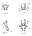
- Rivet 202 intended for use in association with plate 70 of FIGS. 14-15, is shown and is also shown in detail in cross section in FIGS. 19 and 20.
- Rivet 202 has a head 204, a shaft 206, and an elongated bottom segment 208 for fitting within the corresponding opening 200 in plate 70.
- the lower surface 210 of the head 204 of the rivet 202 has a bearing surface, such as on the bottom of locking element 20, 21, for engaging the top surface 39 of the bone screw head 32.
- the upper surface of the elongated bottom segment 208 can have a camming surface for cooperating with the camming surface 17 of the bottom of plate 70 to hold the rivet 202 in the locked position against the bone screw head 32, as shown in FIG. 15. While the rivet of FIG. 18 is a separate, removable component from the plate, the rivets, and particularly those for use with the end locking holes, can be formed as part of the plate during the manufacturing process of the plate and rivet can be non removable if so desired.
- the bearing surface of the rivet 202 may also be cammed to prevent the rivet from unlocking once the cammed portion passes over the screw head.
- Each of the above embodiments provides tight attachment of the locking element relative the bone screw 30 and relevant plate.
- the locking element can be in the form of threaded locking cap 300 shown in FIG. 23.
- the threaded locking cap 300 has a thread 302 on its outer circumference corresponding to the thread 303 on the inner circumference of the locking element depressions 304 in the top of plate 230 shown in FIG. 22.
- the locking cap 300 is relatively thin, particularly compared to its width.
- the top 305 of locking cap 300 may be provided with a noncircular recess or through hole 306 for receiving a similarly configured driving tool or employ other tool engaging means.
- Plate 400 has an opening in its top surface for insertion of the thin locking member 412, a recess 402 associated with each of the bone screw receiving holes 408 and a slot 410 in the side wall of the bone screw receiving holes 408 to permit the thin locking member 412, having a series of thin projections or blades 414, thinner than the slot 410, that give this locking member 412 an appearance similar to that of a propeller.
- the thin locking member 412 is able to be rotated within the plate so as to not cover the bone screw holes, thus allowing the thin locking member 412 to be pre-installed prior to the installation of the bone screws by the surgeon. Limited rotation of the thin locking member 412 allows the blades 414 to protrude through the slot 410 and to cover a portion of the top of the associated bone screws 30.
- the blades 414 of the thin locking member 412 are flexible and, when rotated, slide over the top surface 39 of the bone screw head 32 to lock the bone screw 30 in place.
- each of the embodiments of the locking element is capable of locking more than one bone screw 30. It is appreciated that the various multiple locking plates and locking element combinations are capable of locking as many as four bone screws at once, but are equally effective for locking a lesser number or none at all, that is securing itself to the plate.
- each of the above described locking element embodiments is to have a driver engagement means, in these cases for example, a recess 24 as large as the recess 34 in the bone screws 30 so that the same tool can be used to turn both the bone screws 30 and the locking elements.
- the locking elements are sufficiently strong and have sufficient mass so as to be able to withstand being locked without breakage.
- Bone screw 30' is a variable angle screw having a head 32' with a rounded top and has neck below the head 32' with relieved portions 33'a and 33'b to allow universal motion of the bone screw 30' within the bone screw receiving hole of a plate as the relieved portions provide clearance for the screw to move.
- bone screw 30' may be secured to the plate by a locking element that prevents the screw from backing out, but allows the locking element to bear down on the top of the screw head 32' still move relative to the plate.
- the bottom surface of the seat of the bone screw receiving hole and the bottom of the screw head 32' may be roughened to provide some resistance to movement of the screw head 32' within the bone screw receiving hole and/or the lock may bind the screw head with sufficient force such that once the lock is tightened no movement of the screw within the plate is possible.
- the multiple locking elements have a number of cutout portions having an arc with a radius greater than that of the bone screw head.
- preinstallable multiple locking elements can have a configuration without any cutout portions and still permit for clearance of the bone screw head.
- FIGS. 31A-31D Some examples of such locking elements are shown in FIGS. 31A-31D in which alternative embodiments of locking elements 20a-20d without cutout portions and in which the bone screws can be installed into the bone screw receiving hole 6 even when the locking element is pre-installed to the plate.
- the locking elements may be rotated in the direction of arrow A to bear upon at least a portion of the screw head to lock the bone screws to the plate.
- each locking element 20, 21 is provided at its center with a noncircular recess 24, such as shown in FIG. 9 which is engageable by an appropriate manipulation tool, such as shown in FIGS. 33-35.
- the associated tool would have a hex head, it is appreciated that other shapes of recesses in the head 23 may be used or other male or female driver engaging means may be used without departing from the scope of the present invention.
- the thread of each locking hole 12 and of each locking element 20, 21 has a close tolerance so that they will reliably retain their orientations so as to permit introduction of bone screws 30 into bone screw receiving holes 6, 8 without interference. Alternatively, the threads can be slightly mismatched or a thread or threads can be made irregular or imperfect.
- FIG. 71 an alternative multiple locking plate 990 is shown having additional intermediate bone screw receiving holes 980 and, associated locking elements 960 for locking the bone screws 30 in place.
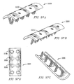
- FIGS. 72A-72H various plates 700a-h are shown. Each of these plates 700a-h have bone screws inserted through the bone screw receiving holes 6 and then locked in place. As shown in Figures 72A-72H, one locking element 710, or two locking elements can be used to lock four bone screws in place. In FIGS. 72A-72H, each of plates 700a-h is shown with the locking elements in their open orientation, before being rotated to lock the bone screws. Plates 700a-700h each have locking elements 710 for locking bone screws inserted into bone screw receiving hole 6 of the plate.
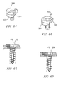
- FIG. 24 provides a side view of one embodiment of a bone screw 30 for use with a plating system according to the present invention.
- Bone screw 30 has a bone screw head 32, a shaft 33, and a tip 36.
- FIG. 27 is a top view of the bone screw 30.
- a profiled recess 34 which may have the same form as the recess 24 of each locking element 20, 21 in which case it may be turned with the same tool as that employed for turning locking elements 20, 21. It is appreciated that the driver engaging portion of the bone screw 30 could be slotted, and be either male or female.
- the bone screw head 32 is stepped, with the first lower head portion 35 being contiguous with the screw shank 33 and has a smaller diameter than the upper portion of the bone screw head 32.
- each bone screw receiving hole 6, 8 of plate 2 has a countersunk region 14 matching the diameter of the upper portion of the bone screw head 32 and dimensioned for an interference fit.
- the lower portion 35 of the bone screw head 32 is dimensioned to achieve an interference fit with its associated portion of bone screw receiving holes 6, 8.
- the larger diameter upper portion of bone screw head 32 assures that the bone screw 30 cannot be advanced completely through bone screw receiving holes 6, 8 of plate 2.
- the bone screw 30 passes completely through the upper surface of plate 2 without engaging the upper surface in any way.
- the head 32 of screw 30 passes unobstructed through the upper surface of the plate until the lower surface of enlarged screw head 32 engages the upper face of the narrowed bone screw receiving portion at the midsubstance or below the midsubstance of the plate.
- This is considered optimal for allowing for the greatest screw to plate stability, even absent the lock, against all forces except those reverse the path of insertion, while still providing for the greatest plate strength beneath the bone screw head 23.
- a sheer vertical circumferential wall is best able to constrain the motion of a screw, if the head is similarly configured and there is little tolerance between them.
- Placing the support of the head near the mid thickness of the plate is preferred as it allows the upper head to remain large to accommodate the recess for the driver without being weakened, while placing the support of the head away from the upper surface of the plate allows the screw head to be deep into the plate. Placing the support of the head at approximately the mid thickness of the plate assures plenty of plate material beneath the head to support while providing adequate head length above and below the contact point to prevent the contact point from acting as a fulcrum by providing adequate lever arms to prevent unwanted motion.
- bone screw head 32' is tapered in the direction from the top of the bone screw head 32' toward screw tip 36'. Again, the bone screw head 32' is dimensioned to achieve an interference fit in the associated bone screw receiving hole 6,8 when the bone screw 30' has been fully installed.
- bone screw receiving holes 6, 8 need not be provided with a countersunk region 14.
- the bone screws 30 and 30' present a unique combination of a tapered screw shaft 33 and a helical thread 31.
- the diameter of screw shaft 33 generally increases from a distal portion of the shaft near the screw tip 36 toward proximal portion of the shaft near screw head 32. In the preferred embodiment, the rate of increase in diameter is also greater near the bone screw head 32. Such a shape avoids stress risers and provides increased strength to the screw at the screw-plate junction, where it is needed the most.
- the tapering of screw shaft 33 may have a concave form, as shown in FIG. 24, or may be linear. The distal portion of the screw shaft 33 may assume a constant diameter.
- the thread 31 of the bone screw 30 has a substantially constant outer, or crest, diameter "d" from below the bone screw head 32 to near the bone screw tip 36.
- the crest diameter of thread 31 may be reduced for preferably one to two turns to facilitate the insertion and penetration of the bone screw 30 into the bone.
- the thread 31 of each bone screw 30 has an outer diameter slightly smaller than the diameter of the lowest portion 35 of the bone screw head 32, which is adjacent the trailing, or upper, end of the associated thread 31.
- the thread 31 is relatively thin, in the direction of the longitudinal axis of the screw, and tapers outwardly, and has a cross section of a triangle, though the sides need not be straight.
- plate holder 870 has a hollow tubular housing 872, with a central rod 874 having a thread 878 at one end for engaging one of the threaded locking holes 12 in plate 2.
- the bottom end of the housing 872 has projections 880, 882 that extend outwardly and then downwardly to fit into the bone screw receiving holes 8 of plate 2 preventing the housing 872 from rotating.
- the central rod 874 is located in the housing 872 such that it can be rotated by rotating a handle (not shown) which is fixed to the central rod 874 at its upper end.
- FIG. 39A an alternative embodiment of the plate holder 890 is shown.
- a single solid member 890 has a threaded projection 894 at its bottom end for attachment to the central threaded locking hole 12 in the plate.
- the bottom surface of the holder 890 of this embodiment is contoured so as to match the contours of the top surface of the plate adjacent to the locking hole 12, shown as a depression 14.
- Plate holder 890' has a hollow tubular housing 872' having a handle 891' at its top end and a bottom end 873' configured for insertion into a bone screw receiving holes 6 of a plate.
- a rod 874' having a sharp tip 875' is contained within housing 872' and is spring biased by a spring 875'.
- a lever 893' is provided for advancing rod 874' from within housing 872'.
- Lever 893' has a cammed portion 892' to lock rod 874' in position.
- the bottom end of the housing 872 is slitted to form projections 880, 881, 882, and 883' that are moved outwardly by the shaft of rod 872' above tip 875' in the direction indicated by arrow A when rod 874' is advanced from within housing 872' to engage and lock into the bone screw receiving holes 6 of plate 2 preventing the housing 872' from separating from plate 2.
- the plate holder 890' functions as both a holder for a plate and also as a temporary plate fixation device to hold the plate in the correct position to the bone prior to the insertion of the bone screws. Further, holder 890' can be used to form pilot holes for screw insertion into the bone portions.
- FIG. 32A Certain structural features of hole forming apparatus 60 are shown in greater detail in FIG. 32A.
- the bottom end of housing 62 has a projecting portion 69 dimensioned to fit precisely in a bone screw receiving hole 6 or 8 of plate 2.
- the bottom 71 of the projecting portion 69 is flat in a plane perpendicular to the axis of housing 62.
- the lower end of the pilot hole forming apparatus 60 is threaded so as to engage the thread in the bone screw receiving hole 6, 8 thereby fixing the plate and the pilot hole forming apparatus together, assuring a stable fit between the pilot hole forming apparatus and plate 2.
- the diameter of the leading end 66 of the shaft 64 is small since it has to fit within the small space left between the inside wall of the pilot hole forming apparatus. Since it is only a pilot hole for a self tapping bone screw 30 that is being formed, the small diameter is satisfactory.
- a drill guide 80 having a lower end as shown in FIG. 32B.
- the drill 80 guide consists of a tubular member 82 and a small diameter lower end 84 which is dimensioned to achieve a precise interference fit in the associated bone screw receiving hole 6, 8 of plate 2.
- drill guide 80 has an axial end surface in a plane perpendicular to the longitudinal axis of the drill guide 80 so that when the small diameter portion 84 is fitted into the bone screw receiving hole 6 and the surface surrounding the small diameter portion 84 is flush against the upper surface of plate 2, the axis of the drill guiding bore 86 in drill guide 80 will be precisely perpendicular to the upper and lower surfaces of the associated portion of plate 2.
- the bottom end of the drill guide 80 can be threaded so as to engage to the threaded opening of plate 2.
- Hole forming apparatus 60' is similar to hole forming apparatus 60, except that it has a ball end 62' that fits within bone screw receiving hole 6. As shown in FIG. 32D, the ball end 62' may be oriented at any angle relative to the plate for angular hole formation into the bone. Hole forming apparatus 60' provides for variable angle preparation of the pilot holes for the bone screws relative to the plate.
- bone screws 30 are threaded into the bone 50 while holding plate 2 firmly against the bone 50 with plate holder 800.
- FIG. 33 is a perspective view showing plate 2 of FIGS. 1-5, at a stage of a surgical procedure when bone screws 30 have been fully installed in bones or pieces of the same bone, and locking screws 20, 21 have been rotated to lock three bone screws 30 in place; the left-hand locking screw 20 as viewed has been rotated through an angle of about 45 ⁇ to lock three bone screws 30 in place and the central locking element 21 has been rotated through an angle of about 90 to lock two other bone screws 30 in place.
- one of the bearing surfaces 44 of each locking element 20, 21 rests atop the screw head 32 of a respective bone screw 30.
- locking elements 20, 21 are provided to the user almost fully tightened, but in the open position such that bone screws can be inserted. Full locking of the bone screw requires 90° or less of turning of the locking element and often 45° will suffice to lock the bone screws.
- Installation of the multilock locking element 300 can also be performed with a tool 220 such as shown in FIGS. 34A and 35 having a suitably shaped tip 222 with a length corresponding to the depth of hole 306 in a locking cap 300.
- the end 222 of tool 220 is flared just proximal to the most distal end so that it creates a friction fit with the screw cap 300 for ease of manipulation, and prevents the locking element 300 from falling off the tool 200.
- the tool receiving hole 306 can be flared to cooperatively engage a tool having a tip with a corresponding configuration.
- FIG. 36 is a cross-sectional view in the plane of the center of the two end locking screw holes 6 of plate 2, with two bone screws 30 in their installed positions and locking element 21 in its locking position.
- FIG. 37 is an enlarged view of one of the bone screws 30 in plate 2 of FIG. 36.
- the axis of each screw 30 is generally perpendicular to tangents to the upper and lower surfaces of plate 2 at points which are intersected by the longitudinal axis of the associated bone screw 30.
- bone screws 30 can be directed so as to converge toward one another at a desired angle.
- the curvature of the plate from side to side may be so as to conform to the surface of the bone to which the plate is being applied and the axis of the paired screw hole may deviate from being perpendicular to the plate when viewed on end to achieve the optimal convergence.
- a "claw" of a rigid triangular frame structure is obtained at each pair of bone screws 30 such that the attachment of plate 2 to the bone would be highly secure due to the trapping of a wedged mass of bone material between the angled bone screws, even if any thread stripping should occur.
- the "claw” may be further formed by three angled bone screws in a tripod configuration or by four bone screws in a four sided claw configuration.
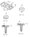
- FIGS. 40-45 are views of a first embodiment of a single locking plate system generally referred to by the numeral 600.
- Plate 600 has the same contour as plate 2 shown in FIGS. 1-5.
- Plate 600 has a bottom surface 27 for placement against bone portions, wherein a substantial portion of bottom surface 27 is either flat and/or convex along the longitudinal axis of the plate though a lesser portion of bottom surface 27 may be otherwise configured.
- plate 600 contains bone screw receiving holes 602 which are internally threaded 603 for receiving corresponding locking elements in the form of a locking cap 610, shown in Figures 49-52.
- the bone screw hole 602 may have an outer diameter appropriate to the screw diameter appropriate to the bone(s) for which the plating system is to be applied.
- a bone screw of a diameter of 4.0 to 6.5 mm would be used and generally the screw head would be slightly larger in diameter.
- the opening in the upper plate surface to receive the locking cap would be similar to generally 0.2 mm to 4.0 mm greater than the screw head size which could be 0.2 mm to 6 mm larger in diameter than the threaded shaft diameter of the bone screw of approximately 5 mm with a preferred range of 4-6 mm though possibly greater.
- Cap attaching means other than threads may be used, such as bayonet type attachment elements.
- each bone screw receiving hole 602 of plate 600 has an inwardly stepped portion of properly selected dimensions for retaining an associated bone screw 170, as shown in FIGS. 46-48.
- the difference between the bone screw 170 used in the single locking embodiment of the plate from the bone screw used in association with the multiple locking plate is essentially due to the fact that whereas in the multiple locking plate embodiment the locking elements slide over a portion of the top 39 of the screw head 32 by a pressing, camming, or ramp action, in the single locking embodiment the locking cap 610 presses directly on the head 172 of the bone screw 170. Therefore, the head 172 of the bone screw 170 of the present embodiment need not be smooth.
- FIG. 55 shows two bone screws 170 and associated threaded locking caps 610 in their fully installed positions. In these positions, head portions 174 and 176 of each bone screw 170 form an interference fit with corresponding portions of an associated bone screw receiving hole 602. Rim 612 of each threaded locking cap 610 forms an interference fit with upper portion 178 of the head of its associated bone screw 170. Because the thread 608 of each locking cap 610 mates precisely with the internal thread in an associated bone screw receiving hole 602, each threaded locking cap 610 is additionally subjected to a clamping force between associated head portion 178 and the internal threads 603 of associated bone screw receiving hole 602. Preferably the rounded head 614 of each threaded locking cap 610 assures that the upper surface of an assembled plating system will be free of sharp edges, or projections.
- FIG. 45 is a top plan view of the plate 600 partially installed, with threaded locking caps 600 installed in bone screw receiving holes 602.
- FIGS. 47-49 show a bone screw 170 for use with the single locking plating system according to the invention.
- Bone screw 170 differs from bone screw 30 previously described in detail, only with regard to the stepped configuration of head 172.
- bone screw 170 includes a lower portion 174 which is contiguous with the screw shank and has a reduced diameter equal to the maximum diameter of the shank 176.
- Portion 178 of head 172 also has smaller diameter than lower portion 174.
- the thread 182 has the same configuration as for the bone screw 30 discussed above. However, either embodiment of bone screws can be used with any of the plates.
- the bone screws 170 for use in the single locking plating system are preferably solid, where the screws adjoin the lower plate surface, where as some screws used with prior art plates are hollow and are prone to breakage, the only recess in the heads of the present invention screws being for engagement of the tip 222 of driving tool 220 and with the recess being above the critical area of the lower plate surface screw junction. Therefore, these bone screws 170 remain robust.
- the screw heads are not deeply slitted into portions as per some prior art screws and the locking caps do not impose a radial outer force to expand the bone screw heads, so again the screw heads of the present invention are not spread apart and stressed and weakened, and so remain robust.
- variable angle screws 30' shown in FIG. 30B may be used in association with the single-lock plating system of the present invention.
- the plate 500 may have any contour as any of the plates of the present invention appropriate for skeletal use and in which a substantial portion of the lower surface of the plate is either flat and/or convex along the longitudinal axis of the plate.
- locking element 506 may have a cutout portion with a radius greater than the radius of a bone screw head as is shown in connection with locking element 508 in FIG. 64.
- the heads 507 and 526 of the locking elements 508 and 522 have a recess 510 and 524 corresponding to the radius of the bone screw openings 502 and 528 so that the locking element 508 and 522 may be installed in place prior to the insertion of the bone screw 170 into the bone screw receiving hole 502 and 528.
- the locking elements 508 and 522 are rotated, a portion of its head extends over the top of the head of bone screw 170 to lock it in place.
- the bottom surface of the locking screws 508 and 522 can have a ramped, cammed, or other configuration for engagement with at least a portion of the screw head.
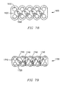
- a locking plate 900 is shown in which there are a number of bone screw receiving holes 950 along the longitudinal axis of plate 900.
- the close spacing and increased number of bone screw receiving holes permits the surgeon to locate appropriate holes to be aligned with each of the bone portions to be fixated, as well as allowing for more points of fixation to the bone.
- FIG. 69A an alternative embodiment of the plate of the present invention is shown and generally referred to by the numeral 960.
- the plate 960 has multiple bone screw receiving holes 970 passing through plate 960.
- the bone screw receiving holes 970 are spaced apart in a staggered configuration such that the center point of each of the bone screw receiving holes 970 are on transverse lines that are offset from one another.
- the center point of the bone screw receiving holes 970 are also offset from the midline of plate 970, but with less longitudinal distance between one another, while providing for sufficient distance between holes 970 to assure plate strength, than plate 900 shown in FIG. 68.
- plate 960 is shown and generally referred to by the numeral 960'.
- Plate 960' has the same staggered pattern of bone screw holes 970 as plate 960 to permit crossing over of two bone screws 30.
- plate 960' has an overall configuration suitable for use in the spine including the anterior cervical spine.
- an embodiment could have openings 910 in lobed portions at the corner of plate 960' and recesses 930 for use with a compressing apparatus.
- Plate 960 could have additional pairs of lobes along the plate length. It is appreciated that the overall configuration of plate 960' can vary as can the offset pattern of the bone screw holes.
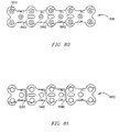
- the offset pattern of bone screw receiving holes 970 permits longer bone screws 30 to be used than would otherwise be possible if the screws were aligned in transverse pairs without having bone screws 30 touch each other, due to the fact that the bone screws 30 are in different planes, and each bone screw 30 gets to travel a much longer diagonal path in crossing the sagittal midline, providing greater fixation.
- the shafts of two bone screws 30 cross over in close proximity to each other and define an included angle IA preferably between 25 to 90 degrees.
- IA preferably between 25 to 90 degrees.
- FIGS. 70B-70D end views of alternative embodiments of plate 960' are shown wherein the bottom surface of the plate may be in the transverse plane relatively flat, curved, or otherwise configured to fit the surface configuration of the bone or bones to which the plate is to be applied.
- plates 960' overall are generally shaped to conform to the bone(s) B to which they are applied.
- Segmentable plate 1000 has an elongated body with a plurality of bone screw receiving holes 1010 spaced apart along a substantial portion of the length of the segmentable plate 1000.
- Segmentable plate 1000 has a multiple locking system 1020 for locking bone screws to plate 1010 as described above in connection with multi-lock plate 2 shown in FIGS. 1-7.
- Plate 1000 is preferably, but not limited to being made of a malleable material, such as titanium or one of its surgically acceptable alloys.
- Plate 1000 comprises a plurality of segments 1030-1038 which can be separated from each other.
- a first segment 1030 of plate 1000 is marked by a segmentation zone 1040 along which the plate may be separated to separate first segment 1030 from the remainder of plate 1000.
- Segmentation zone 1040 can be any type of scoring which creates a place of least resistance along which when the plate 1000 is bent sufficiently to create a separation in the material of plate 1000, the separation will occur along the segmentation zone.
- segmentation zone 1040 may be formed by removing approximately 0.25 mm to 0.5 mm of material in total from the upper surface, lower surface or both upper and low plate surfaces combined of the plate.
- the scoring can be relatively thicker or thinner in width, variable in depth and of variable shape (e.g. "V" notched, rounded, etc.) to achieve the desired qualities.
- plate 1000 is made of titanium, the inherent qualities of titanium are such that the plate may be separated simply by bending the plate sufficiently along segmentation zone 1040 while supporting the plate with appropriate plate holders to either side of segmentation zone 1040 and then bending the plate towards its original position at which time the plate will separate apart along the segmentation zone 1040, providing a sufficiently clean edge suitable for surgical use.
- a set of four segmentable plates 1000 to cover the various combinations required for application to one to four levels of the cervical spine would include a first segmentable plate having a first segment with a spacing distance between the bone screw receiving holes of 10 mm, and subsequent segments similarly spaced at 10 mm intervals between the holes; a second segmentable plate having a first segment with a spacing distance between the bone screw receiving holes of 12.5 mm, and subsequent segments spaced at 12.5 mm intervals between the screw holes; a third segmentable plate having a first segment with a spacing distance between the bone screw receiving holes of 15 mm and subsequent segments spaced apart at 15 mm intervals between the holes; and a fourth segmentable plate having a first segment with a spacing distance between the bone screw receiving holes of 17.5 mm and subsequent segments spaced apart at 17.5 mm intervals between the holes
- the longitudinal spacing between the bone screw receiving holes 1010 may be varied by changing the length of the portion of plate 1000 between bone screw receiving holes 1010 as illustrated by the dotted lines in FIG. 74.
- the described plates may be separable into a multitude of usable portions, as would be desirable for manufacturing purposes and possibly for clinical use, because of regulatory issues involving the identification of each implant with a distinct and singular implant identification number for tracking purposes it may be desirable to configure the plates of the present invention such that each plate will yield only one usable portion.
- the segmentation zone 1040 is made as shown in FIG. 79, such that the unused, separated pieces of the segmentable plates would not be usable as plates and would be discarded.
- the ability to separate a plate into segments also provides significant advantages in the manufacturing process.
- the cost of the material is not as significant as the labor involved in the manufacturing. Therefore, the manufacturer can cast one long segmentable plate which can then be separated in the later manufacturing stages to yield multiple plates at an overall lower cost.
- the plate were in the alternative to be manufactured by machining from solid stock, great labor could be saved by fixturing and securing a single long plate that is later separable into multiple plates rather than having to fixture and secure each of those plates individually.
- FIGS. 75-79 various segmentable plates 1300-1700 are shown for application in reconstructive surgery.
- Plates 1300-1700 have bone screw receiving holes 1310-1710, locking elements 1320-1720, and separation zones 1340-1740 respectively.
- the segmentable plates 1300-1700 can be used to align and maintain the broken bone portions in correct spatial relationship.
- the curved characteristics of an eye socket would require the plate used to repair the socket to match the curvature.
- the segmentable plates 1300-1700 are made of a malleable metal, the malleability of which is enhanced by the segmentation of the plate, and can be easily contoured by the surgeon to the appropriate curvature.
- the correct length of the segmentable plate can also be easily be selected by the surgeon by separating the plate at the appropriate segment as described above in connection with plate 1000 shown in FIG. 73.
- the separation zones allow the plate to be more easily bent, but without separating.
- the present invention makes a virtue of the material property of that alloy in that it may be bent without damage, but fails with surprisingly little force if first bent and then bent back. Back bending is therefore only done for plate separation and is not needed for contouring which requires only primary bending.
- segmentable plate 1800 and 1900 alternative embodiments of the segmentable plate are shown and generally referred to by the numeral 1800 and 1900.
- Segmentable plates 1800-1900 may be segmented at segmentation zones 1840 and 1940 as described above in connection with the multiple lock embodiment of the segmentation plate 1000.
- the passive dynamic system 2000 is shown having a plate with a screw hole 2010 passing through the top and bottom surfaces of the plate 2020 for receiving a bone screw 2030.
- the screw hole 2010 has a round opening 2040 at the top of the plate 2020 and an opening 2050 in the bottom of the plate that is in part coaxial with the top opening 2040, but extends in one direction to form an oblong.
- the rounded head 2032 of bone screw 2030 is prevented from backing out of plate 2020 with a locking element 2060 that is engaged to plate 2020, while the shaft of bone screw 2030 is capable of angular motion in the direction of arrow A relative to plate 2020, since there is space in the oblong-shaped bottom opening 2040 of the screw hole 2010 for the shaft of the bone screw 2030 to travel in the one permitted direction relative to the plate 2020.
- the passive dynamic system allows bone screw 2030 to move relative to plate 2020 even after being locked to plate when a force is presented against the screw. This system does not cause screw movement, but only allows for movement of the screw to occur and this is a "passive" system. Nevertheless, screw 2030 retains the ability to resist any unwanted motion in all other directions.
- the use of variable screw 30' as already described may also allow for passive dynamic action, but is not generally preferred as it does not limit the motion to but a single direction.
- a self-compressing system 2100 comprising a plate 2120 having a bone screw receiving 2110 hole with a top opening 2140 that is preferably but not necessarily round, and having a rounded recessed portion 2142 is shown.
- the bone screw receiving hole has bottom opening 2150 that is smaller in diameter than the top opening 2140 and has a central longitudinal axis 2153 that is offset from the central longitudinal axis 2151 of the top opening 2140.
- the bone screw has a rounded head portion 2132 which fits within the rounded bottom 2142 of the top opening 2140 and permits movement of the screw head 2132 within the top opening in order to provide the appropriate angle A of the bone screw shaft with respect to the plate 2120 as the bone screw shaft passes through the bottom opening 2150.
- the self-compressing system As the bone screw 2130 is being locked to the plate 2120 with a locking element 2160, the-locking element 2160 puts pressure on the bone screw head 2132 to make the bone screw 2130 move in one direction. The bone screw 2130 cannot move back once it is locked to the plate 2120 by the locking element 2160.
- the purpose of the self-compressing system 2100 is to provide a fixed and locked angle A on the bone screw 2130 for providing compression of bone portions.
- the active dynamic system 2200 of the present invention is shown comprising a screw 2230 that is mounted to a plate 2220 under a spring loaded force, such as with a Belville type washer 2270 that applies a selected force to the screw 2230.
- the bone screw 2230 will move in the direction of the force that is being applied as bottom opening 2250 of the bone screw receiving hole is oblong shaped.
- the big end 2272 of the spring formed by washer 2270 bears down on the screw head 2232 away from the direction that the bone screw 2230 is to be moved.
- plate, screw, hole, and spring it is simple to determine correct resistance, that being an amount less than would separate the bone.
- the washer 2270 may also have a tab 2290 which fits into a recess 2292 formed within the top opening in order to facilitate proper orientation of the washer when placed within the opening or alternatively the washer 2270 may have a non-circular shape so as to not rotate when positioned.
- a pre-loaded force is applied to a bone screw that keeps the screw in a certain orientation with respect to the plate.
- the bone screw will only move further in the pre-oriented direction if there is space available and if there is no opposing force present to counteract the pre-loaded force on the screw.
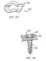
- Plate 3000 has a bottom surface 3027 that is convex along a substantial portion of the longitudinal axis of the plate and is concave along the transverse axis of the plate 3000.
- Plate 3000 has a single-locking element 3022 for locking a single bone screw 3030 to plate 3000.
- Plate 3100 has a bottom surface that is flat along a substantial portion of the longitudinal axis of the plate and is concave along the transverse axis of the plate.
- Plate 3100 has a multiple locking element 3120 for locking two bone screws 3130 and single locking elements 3122 for locking individual bone screws 3130 to plate 3100.
- Bone screw receiving holes 3140 are staggered such that the center point of each of the bone screw receiving holes 3142 and 3144 are on transverse lines that are offset from one another. The center point of the bone screw receiving holes 970 are also offset from the midline of plate.
- the shafts of two bone screws 30 cross over in close proximity to each other and define an included angle IA between 25 to 9.0 degrees.
- Such a crossed configuration of bone screws 30 provides an extremely stable engagement of plate 960 to the bone as they are very close together and diagonally crossed within the same bone, thus trapping an area of bone between them.
- Plate 3100 comprises a plurality of segments 3150-3156 which can be separated from each other.
- a first segment 3150 of plate 3100 is marked by segmentation zones 3160-3164 along which the plate may be separated to separate segments 3150, 3152, 3154, or 3156 from the remainder of plate 3100.
- Segmentation zones 3160-3164 can be any type of scoring which creates a place of least resistance along which when the plate 3100 is bent sufficiently to create a separation in the material of plate 3100, the separation will occur along the segmentation zone.
- plate 3100 may include one or more of the screw-lock-plating systems 2000, 2100, or 2200 described above in FIGS. 82-84.
- Plate 3200 has a bottom surface that is flat along a substantial portion of the longitudinal axis of the plate and is concave along the transverse axis of the plate and has an upper surface that is concave along the transverse axis of the plate 3200.
- plate 3000 may include one or more of the screw-lock-plating systems 2000, 2100, or 2200 described above in FIGS. 82-94.
Abstract
Claims (17)
- Système à plaque d'ostéosynthèse squelettique pour aligner et maintenir des parties osseuses du même os ou d'os différents dans une relation spatiale sélectionnée pour la cicatrisation ou la fusion des parties osseuses, comprenant :une plaque (2, 70, 120, 230, 400, 700a-h, 990, 1000, 1100, 1300, 1400, 1500, 1600, 1700) ayant une longueur suffisante pour recouvrir au moins deux parties osseuses, ladite plaque ayant une surface supérieure et une surface inférieure (27) pour la mise en place contre les parties osseuses, ladite plaque ayant une pluralité de trous de réception de vis à os (12) s'étendant à travers ladite plaque de ladite surface supérieure à ladite surface inférieure, au moins un premier trou de ladite pluralité de trous de réception de vis à os étant associé à une première des parties osseuses et au moins un second trou de ladite pluralité de trous de réception de vis à os étant associé à une seconde des parties osseuses ; caractérisé en ce que :ladite surface inférieure (27) de ladite plaque est convexe le long d'une partie significative de l'axe longitudinal de ladite plaque, ladite plaque comprenant un élément à blocage multiple (20, 21, 202, 300, 412, 710a-h, 1020, 1120, 1320, 1420, 1620, 1720) pour bloquer sur ladite plaque au moins deux vis à os (30) pouvant être insérées dans au moins deux de ladite pluralité de trous de réception de vis à os, respectivement, ledit élément de blocage lorsqu'il est couplé à ladite plaque, étant mobile d'au moins une première position à une seconde position, ledit élément de blocage étant configuré afin de permettre l'insertion d'au moins une vis à os (30) dans chacun desdits premier et second trous de réception de vis à os (12), lorsqu'il est dans ladite première position et étant configuré afin de s'appuyer contre au moins une partie de chacune des vis à os dans lesdits premier et second trous de réception de vis lors du passage dans ladite seconde position, ledit élément de blocage étant adapté pour être couplé à ladite plaque avant l'insertion des vis à os (30) dans les trous de réception de vis à os (12).
- Système à plaque d'ostéosynthèse squelettique selon la revendication 1, la plaque comprenant en outre un évidement (14), dans lequel ledit élément de blocage (20, 21, 202, 300, 412, 710a-h, 1020, 1120, 1320, 1420, 1620, 1720) peut être mis en prise de manière mobile dans ledit évidement.
- Système à plaque d'ostéosynthèse squelettique selon la revendication 1, dans lequel ledit élément de blocage (20, 21, 202, 300, 412, 710a-h, 1020, 1120, 1320, 1420, 1620, 1720) est fixé de manière permanente à ladite plaque.
- Système à plaque d'ostéosynthèse squelettique selon la revendication 1, dans lequel ledit élément de blocage (20, 21, 202, 300, 412, 710a-h, 1020, 1120, 1320, 1420, 1620, 1720) est préinstallé avant l'insertion des vis à os dans lesdits trous de réception de vis à os.
- Système à plaque d'ostéosynthèse squelettique selon la revendication 1, dans lequel ledit élément de blocage (20, 21, 202, 300, 412, 710a-h, 1020, 1120, 1320, 1420, 1620, 1720) bloque au moins trois vis à os.
- Système à plaque d'ostéosynthèse squelettique selon la revendication 1, dans lequel ledit élément de blocage comprend un rivet (202).
- Système à plaque d'ostéosynthèse squelettique selon la revendication 1, dans lequel ledit élément de blocage (20, 21, 202, 300, 412, 710a-h, 1020, 1120, 1320, 1420, 1620, 1720) bloque au moins quatre vis à os (30).
- Système à plaque d'ostéosynthèse squelettique selon la revendication 1, la plaque comprenant en outre un évidement (14) associé avec au moins deux trous de ladite pluralité de trous de réception de vis à os (12), ledit élément de blocage (20, 21, 202, 300, 412, 710a-h, 1020, 1120, 1320, 1420, 1620, 1720) étant mobile dans ledit évidement d'une première position à une seconde position pour bloquer au moins deux vis à os sur ladite plaque, ledit élément de blocage étant configuré afin de permettre l'insertion d'au moins une vis à os (30) dans au moins deux trous de ladite pluralité de trous de réception de vis à os lorsqu'il est dans ladite première position.
- Système à plaque d'ostéosynthèse squelettique selon la revendication 1, dans lequel au moins deux desdits trous de réception de vis à os (970) sont par paire, au moins un premier trou de réception de vis à os dans lesdits trous de réception de vis à os en paire étant positionné en décalage par rapport à un second trou de réception de vis à os dans ladite paire, et les points centraux desdits premier et second trous de réception de vis à os en paire étant sur des lignes transversales différentes le long de l'axe transversal de ladite plaque, de sorte que les axes longitudinaux centraux desdits premiers trous de réception de vis à os en paire forment un angle inclus l'un par rapport à l'autre supérieur à 25 degrés et inférieur à 90 degrés.
- Système à plaque d'ostéosynthèse squelettique selon la revendication 1, la plaque comprenant en outre au moins une zone de segmentation (1040, 1140, 1340, 1440, 1540, 1640, 1740, 1840, 1940, 3160), dans lequel ladite plaque peut être séparée en plus d'un segment.
- Système à plaque d'ostéosynthèse squelettique selon la revendication 1, dans lequel au moins l'un desdits premiers trous de réception de vis à os a une ouverture ronde (2240) au niveau de ladite surface supérieure de ladite plaque et une ouverture oblongue (2250) au niveau de ladite surface inférieure de ladite plaque, ladite ouverture oblongue étant coaxiale au moins en partie avec ladite ouverture ronde, dans lequel lorsqu'une vis à os est insérée dans ledit trou de réception de vis à os et bloquée sur ladite plaque, la vis à os est capable d'un mouvement passif par rapport à ladite plaque.
- Système à plaque d'ostéosynthèse squelettique selon la revendication 11, comprenant en outre des moyens pour appliquer une force sélective (2270) sur la tête de vis d'une vis à os insérée dans ledit trou de réception de vis à os et bloquée sur ladite plaque pour provoquer un mouvement actif de ladite vis à os par rapport à ladite plaque.
- Système à plaque d'ostéosynthèse squelettique selon la revendication 1, dans lequel au moins l'un desdits trous de réception de vis à os a une première ouverture (2140) au niveau de ladite surface supérieure de ladite plaque avec un siège arrondi (2142) et a une seconde ouverture (2150) au niveau de ladite surface inférieure de ladite plaque, ladite seconde ouverture ayant un axe longitudinal central décalé par rapport à l'axe longitudinal central de ladite première ouverture, dans lequel lorsqu'une vis à os est insérée dans au moins l'un desdits trous de réception de vis à os et bloquée sur ladite plaque, on ménage un angle fixe et bloqué de la vis à os par rapport à ladite plaque.
- Système à plaque d'ostéosynthèse squelettique selon l'une quelconque des revendications précédentes, en combinaison avec une substance favorisant la fusion pour faciliter la croissance osseuse.
- Système à plaque d'ostéosynthèse squelettique selon la revendication 14, dans lequel ladite substance favorisant la fusion comprend au moins l'un parmi l'os, la protéine morphogénétique osseuse, l'hydroxyapatite, et le phosphate tricalcique d'hydroxyapatite.
- Système à plaque d'ostéosynthèse squelettique selon l'une quelconque des revendications précédentes, dans lequel ladite plaque est au moins en partie résorbable.
- Système à plaque d'ostéosynthèse squelettique selon l'une quelconque des revendications précédentes, en combinaison avec un greffon osseux.
Priority Applications (1)
| Application Number | Priority Date | Filing Date | Title |
|---|---|---|---|
| EP07112067A EP1847229A3 (fr) | 1997-02-11 | 1998-02-11 | Système de plaquage squelettique à verrou unique |
Applications Claiming Priority (5)
| Application Number | Priority Date | Filing Date | Title |
|---|---|---|---|
| US3713997P | 1997-02-11 | 1997-02-11 | |
| US37139P | 1997-02-11 | ||
| PCT/US1998/002213 WO1998034556A1 (fr) | 1997-02-11 | 1998-02-11 | Systeme pour poser des plaques d'osteosynthese squelettiques |
| US09/022,344 US6139550A (en) | 1997-02-11 | 1998-02-11 | Skeletal plating system |
| 2000-10-04 |
Related Child Applications (1)
| Application Number | Title | Priority Date | Filing Date |
|---|---|---|---|
| EP07112067A Division EP1847229A3 (fr) | 1997-02-11 | 1998-02-11 | Système de plaquage squelettique à verrou unique |
Publications (3)
| Publication Number | Publication Date |
|---|---|
| EP0996385A1 EP0996385A1 (fr) | 2000-05-03 |
| EP0996385A4 EP0996385A4 (fr) | 2001-10-31 |
| EP0996385B1 true EP0996385B1 (fr) | 2008-01-16 |
Family
ID=26695828
Family Applications (1)
| Application Number | Title | Priority Date | Filing Date |
|---|---|---|---|
| EP98906158A Expired - Lifetime EP0996385B1 (fr) | 1997-02-11 | 1998-02-11 | Systeme pour poser des plaques d'osteosynthese squelettiques |
Country Status (7)
| Country | Link |
|---|---|
| US (9) | US6139550A (fr) |
| EP (1) | EP0996385B1 (fr) |
| JP (1) | JP4467647B2 (fr) |
| AU (1) | AU6145998A (fr) |
| CA (2) | CA2523814C (fr) |
| DE (1) | DE69839011T2 (fr) |
| WO (1) | WO1998034556A1 (fr) |
Cited By (2)
| Publication number | Priority date | Publication date | Assignee | Title |
|---|---|---|---|---|
| US9592083B2 (en) | 2013-08-30 | 2017-03-14 | New South Innovations Pty Limited | Spine stabilization device |
| US9931143B2 (en) | 2012-08-31 | 2018-04-03 | New South Innovations Pty Limited | Bone stabilization device and methods of use |
Families Citing this family (571)
| Publication number | Priority date | Publication date | Assignee | Title |
|---|---|---|---|---|
| AU7178698A (en) | 1996-11-15 | 1998-06-03 | Advanced Bio Surfaces, Inc. | Biomaterial system for in situ tissue repair |
| US7201751B2 (en) * | 1997-01-02 | 2007-04-10 | St. Francis Medical Technologies, Inc. | Supplemental spine fixation device |
| US7306628B2 (en) * | 2002-10-29 | 2007-12-11 | St. Francis Medical Technologies | Interspinous process apparatus and method with a selectably expandable spacer |
| US7959652B2 (en) | 2005-04-18 | 2011-06-14 | Kyphon Sarl | Interspinous process implant having deployable wings and method of implantation |
| US6068630A (en) | 1997-01-02 | 2000-05-30 | St. Francis Medical Technologies, Inc. | Spine distraction implant |
| DE69837626T2 (de) | 1997-02-11 | 2007-12-20 | Warsaw Orthopedic, Inc., Warsaw | Platte mit Verriegelungsmechanismus für die vordere Halswirbelsäule |
| CA2523814C (fr) * | 1997-02-11 | 2007-02-06 | Gary Karlin Michelson | Systeme pour poser des plaques d'osteosynthese squelettiques |
| ZA983955B (en) | 1997-05-15 | 2001-08-13 | Sdgi Holdings Inc | Anterior cervical plating system. |
| FR2778088B1 (fr) * | 1998-04-30 | 2000-09-08 | Materiel Orthopedique En Abreg | Implant anterieur notamment pour le rachis cervical |
| US6533786B1 (en) * | 1999-10-13 | 2003-03-18 | Sdgi Holdings, Inc. | Anterior cervical plating system |
| US20040220571A1 (en) * | 1998-04-30 | 2004-11-04 | Richard Assaker | Bone plate assembly |
| US6258089B1 (en) * | 1998-05-19 | 2001-07-10 | Alphatec Manufacturing, Inc. | Anterior cervical plate and fixation system |
| US6187000B1 (en) | 1998-08-20 | 2001-02-13 | Endius Incorporated | Cannula for receiving surgical instruments |
| US6241770B1 (en) | 1999-03-05 | 2001-06-05 | Gary K. Michelson | Interbody spinal fusion implant having an anatomically conformed trailing end |
| US6342055B1 (en) * | 1999-04-29 | 2002-01-29 | Theken Surgical Llc | Bone fixation system |
| US7094239B1 (en) * | 1999-05-05 | 2006-08-22 | Sdgi Holdings, Inc. | Screws of cortical bone and method of manufacture thereof |
| US6261291B1 (en) * | 1999-07-08 | 2001-07-17 | David J. Talaber | Orthopedic implant assembly |
| FR2897259B1 (fr) | 2006-02-15 | 2008-05-09 | Ldr Medical Soc Par Actions Si | Cage intersomatique transforaminale a greffon de fusion intervetebrale et instrument d'implantation de la cage |
| US6224602B1 (en) * | 1999-10-11 | 2001-05-01 | Interpore Cross International | Bone stabilization plate with a secured-locking mechanism for cervical fixation |
| US6692503B2 (en) | 1999-10-13 | 2004-02-17 | Sdgi Holdings, Inc | System and method for securing a plate to the spinal column |
| US6328738B1 (en) * | 1999-11-24 | 2001-12-11 | Loubert Suddaby | Anterior cervical fusion compression plate and screw guide |
| EP1255498B1 (fr) * | 2000-01-27 | 2005-11-23 | SYNTHES AG Chur | Plaque pour osteosynthese |
| US20040153073A1 (en) * | 2000-02-01 | 2004-08-05 | Hand Innovations, Inc. | Orthopedic fixation system including plate element with threaded holes having divergent axes |
| US6767351B2 (en) * | 2000-02-01 | 2004-07-27 | Hand Innovations, Inc. | Fixation system with multidirectional stabilization pegs |
| US7282053B2 (en) * | 2003-03-27 | 2007-10-16 | Depuy Products, Inc. | Method of using fracture fixation plate for performing osteotomy |
| US6706046B2 (en) * | 2000-02-01 | 2004-03-16 | Hand Innovations, Inc. | Intramedullary fixation device for metaphyseal long bone fractures and methods of using the same |
| US6893444B2 (en) * | 2000-02-01 | 2005-05-17 | Hand Innovations, Llc | Bone fracture fixation systems with both multidirectional and unidirectional stabilization pegs |
| US7695502B2 (en) | 2000-02-01 | 2010-04-13 | Depuy Products, Inc. | Bone stabilization system including plate having fixed-angle holes together with unidirectional locking screws and surgeon-directed locking screws |
| US20060041260A1 (en) * | 2000-02-01 | 2006-02-23 | Orbay Jorge L | Fixation system with plate having holes with divergent axes and multidirectional fixators for use therethrough |
| US7857838B2 (en) * | 2003-03-27 | 2010-12-28 | Depuy Products, Inc. | Anatomical distal radius fracture fixation plate |
| FR2810532B1 (fr) * | 2000-06-26 | 2003-05-30 | Stryker Spine Sa | Implant osseux a moyens de blocage annulaires |
| AU757023B2 (en) | 2000-06-26 | 2003-01-30 | Stryker European Holdings I, Llc | Bone screw retaining system |
| US7985247B2 (en) | 2000-08-01 | 2011-07-26 | Zimmer Spine, Inc. | Methods and apparatuses for treating the spine through an access device |
| US7056321B2 (en) | 2000-08-01 | 2006-06-06 | Endius, Incorporated | Method of securing vertebrae |
| US20050038435A1 (en) * | 2000-08-22 | 2005-02-17 | J. Dean Cole | Intramerdullary canal diameter reducer background of the invention |
| US7833250B2 (en) | 2004-11-10 | 2010-11-16 | Jackson Roger P | Polyaxial bone screw with helically wound capture connection |
| US6953462B2 (en) | 2000-10-05 | 2005-10-11 | The Cleveland Clinic Foundation | Apparatus for implantation into bone |
| US6740088B1 (en) | 2000-10-25 | 2004-05-25 | Sdgi Holdings, Inc. | Anterior lumbar plate and method |
| EP1205154A3 (fr) * | 2000-11-08 | 2003-04-02 | Aesculap AG & Co. KG | Dispositif de plaque pour ostéosynthèse et méthode avec une plaque à extension |
| DE10055888C1 (de) * | 2000-11-10 | 2002-04-25 | Biedermann Motech Gmbh | Knochenschraube |
| US6503250B2 (en) * | 2000-11-28 | 2003-01-07 | Kamaljit S. Paul | Bone support assembly |
| US20050010227A1 (en) * | 2000-11-28 | 2005-01-13 | Paul Kamaljit S. | Bone support plate assembly |
| US6726689B2 (en) | 2002-09-06 | 2004-04-27 | Roger P. Jackson | Helical interlocking mating guide and advancement structure |
| US8377100B2 (en) | 2000-12-08 | 2013-02-19 | Roger P. Jackson | Closure for open-headed medical implant |
| US6413259B1 (en) * | 2000-12-14 | 2002-07-02 | Blackstone Medical, Inc | Bone plate assembly including a screw retaining member |
| US6972019B2 (en) | 2001-01-23 | 2005-12-06 | Michelson Gary K | Interbody spinal implant with trailing end adapted to receive bone screws |
| KR20040015670A (ko) * | 2001-01-24 | 2004-02-19 | 트리콘 호울딩즈 리미티드 | 탄탈륨 필름 침착방법 |
| US6673113B2 (en) | 2001-10-18 | 2004-01-06 | Spinecore, Inc. | Intervertebral spacer device having arch shaped spring elements |
| US7169182B2 (en) * | 2001-07-16 | 2007-01-30 | Spinecore, Inc. | Implanting an artificial intervertebral disc |
| US6872210B2 (en) | 2001-02-23 | 2005-03-29 | James P. Hearn | Sternum fixation device |
| US6890355B2 (en) * | 2001-04-02 | 2005-05-10 | Gary K. Michelson | Artificial contoured spinal fusion implants made of a material other than bone |
| FR2823096B1 (fr) * | 2001-04-06 | 2004-03-19 | Materiel Orthopedique En Abreg | Plaque pour dispositif d'osteosynthese des vertebres l5 et s1, dispositif d'osteosynthese incluant une telle plaque, et instrument pour la pose d'une telle plaque |
| US6599290B2 (en) | 2001-04-17 | 2003-07-29 | Ebi, L.P. | Anterior cervical plating system and associated method |
| US20050049594A1 (en) * | 2001-04-20 | 2005-03-03 | Wack Michael A. | Dual locking plate and associated method |
| US7537604B2 (en) * | 2002-11-19 | 2009-05-26 | Acumed Llc | Bone plates with slots |
| US7118573B2 (en) * | 2001-06-04 | 2006-10-10 | Sdgi Holdings, Inc. | Dynamic anterior cervical plate system having moveable segments, instrumentation, and method for installation thereof |
| EP1404225A4 (fr) | 2001-06-04 | 2009-09-16 | Warsaw Orthopedic Inc | Systeme a plaque cervicale anterieure munie de moyens d'ancrage en prise avec les corps de vertebres, plaque de connexion et procede de mise en place y relatif |
| US7097645B2 (en) | 2001-06-04 | 2006-08-29 | Sdgi Holdings, Inc. | Dynamic single-lock anterior cervical plate system having non-detachably fastened and moveable segments |
| US7186256B2 (en) | 2001-06-04 | 2007-03-06 | Warsaw Orthopedic, Inc. | Dynamic, modular, single-lock anterior cervical plate system having assembleable and movable segments |
| US7044952B2 (en) | 2001-06-06 | 2006-05-16 | Sdgi Holdings, Inc. | Dynamic multilock anterior cervical plate system having non-detachably fastened and moveable segments |
| US7041105B2 (en) * | 2001-06-06 | 2006-05-09 | Sdgi Holdings, Inc. | Dynamic, modular, multilock anterior cervical plate system having detachably fastened assembleable and moveable segments |
| EP1408884A1 (fr) * | 2001-07-12 | 2004-04-21 | Osteotech, Inc. | Implant intervertebral comportant une structure resistant au mouvement |
| US6890335B2 (en) * | 2001-08-24 | 2005-05-10 | Zimmer Spine, Inc. | Bone fixation device |
| US6974460B2 (en) * | 2001-09-14 | 2005-12-13 | Stryker Spine | Biased angulation bone fixation assembly |
| US7771477B2 (en) | 2001-10-01 | 2010-08-10 | Spinecore, Inc. | Intervertebral spacer device utilizing a belleville washer having radially spaced concentric grooves |
| US7713302B2 (en) | 2001-10-01 | 2010-05-11 | Spinecore, Inc. | Intervertebral spacer device utilizing a spirally slotted belleville washer having radially spaced concentric grooves |
| WO2003032848A2 (fr) * | 2001-10-19 | 2003-04-24 | Baylor College Of Medicine | Dispositifs et systemes de compression osseuse, et procede de remodelage osseux, ainsi que leur utilisation |
| US6783527B2 (en) | 2001-10-30 | 2004-08-31 | Sdgi Holdings, Inc. | Flexible spinal stabilization system and method |
| US6679883B2 (en) | 2001-10-31 | 2004-01-20 | Ortho Development Corporation | Cervical plate for stabilizing the human spine |
| US7766947B2 (en) | 2001-10-31 | 2010-08-03 | Ortho Development Corporation | Cervical plate for stabilizing the human spine |
| US6755833B1 (en) * | 2001-12-14 | 2004-06-29 | Kamaljit S. Paul | Bone support assembly |
| US7008426B2 (en) | 2001-12-14 | 2006-03-07 | Paul Kamaljit S | Bone treatment plate assembly |
| US7070599B2 (en) * | 2002-07-24 | 2006-07-04 | Paul Kamaljit S | Bone support assembly |
| US7066937B2 (en) | 2002-02-13 | 2006-06-27 | Endius Incorporated | Apparatus for connecting a longitudinal member to a bone portion |
| US7879075B2 (en) | 2002-02-13 | 2011-02-01 | Zimmer Spine, Inc. | Methods for connecting a longitudinal member to a bone portion |
| AR038680A1 (es) | 2002-02-19 | 2005-01-26 | Synthes Ag | Implante intervertebral |
| US6695846B2 (en) | 2002-03-12 | 2004-02-24 | Spinal Innovations, Llc | Bone plate and screw retaining mechanism |
| US20030187443A1 (en) * | 2002-03-27 | 2003-10-02 | Carl Lauryssen | Anterior bone plate system and method of use |
| US8038713B2 (en) | 2002-04-23 | 2011-10-18 | Spinecore, Inc. | Two-component artificial disc replacements |
| US20080027548A9 (en) | 2002-04-12 | 2008-01-31 | Ferree Bret A | Spacerless artificial disc replacements |
| US6706068B2 (en) | 2002-04-23 | 2004-03-16 | Bret A. Ferree | Artificial disc replacements with natural kinematics |
| US7799086B2 (en) * | 2002-04-25 | 2010-09-21 | Zimmer Technology, Inc. | Modular bone implant, tools, and method |
| US20030233093A1 (en) * | 2002-06-13 | 2003-12-18 | Randall Moles | Osteogenic distraction device |
| US7077843B2 (en) * | 2002-06-24 | 2006-07-18 | Lanx, Llc | Cervical plate |
| US7175623B2 (en) * | 2002-06-24 | 2007-02-13 | Lanx, Llc | Cervical plate with backout protection |
| US7001389B1 (en) | 2002-07-05 | 2006-02-21 | Navarro Richard R | Fixed and variable locking fixation assembly |
| US7004944B2 (en) * | 2002-07-16 | 2006-02-28 | Sdgi Holdings, Inc. | Bone plate fastener retaining mechanisms and methods |
| US6989012B2 (en) * | 2002-07-16 | 2006-01-24 | Sdgi Holdings, Inc. | Plating system for stabilizing a bony segment |
| NL1021137C2 (nl) | 2002-07-23 | 2004-01-27 | Fondel Finance B V | Steunelement voor bevestiging aan bot. |
| US7060067B2 (en) * | 2002-08-16 | 2006-06-13 | Sdgi Holdings, Inc. | Systems, instrumentation and techniques for retaining fasteners relative to a bone plate |
| US7862597B2 (en) | 2002-08-22 | 2011-01-04 | Warsaw Orthopedic, Inc. | System for stabilizing a portion of the spine |
| US8282673B2 (en) | 2002-09-06 | 2012-10-09 | Jackson Roger P | Anti-splay medical implant closure with multi-surface removal aperture |
| US8876868B2 (en) * | 2002-09-06 | 2014-11-04 | Roger P. Jackson | Helical guide and advancement flange with radially loaded lip |
| US8257402B2 (en) | 2002-09-06 | 2012-09-04 | Jackson Roger P | Closure for rod receiving orthopedic implant having left handed thread removal |
| US20040111090A1 (en) * | 2002-10-03 | 2004-06-10 | The University Of North Carolina At Chapel Hill | Modification of percutaneous intrafocal plate system |
| US7220263B2 (en) * | 2002-10-04 | 2007-05-22 | Seaspine, Inc. | Cervical plate/screw system for immobilizing vertebral bodies |
| FR2845588B1 (fr) * | 2002-10-09 | 2006-12-15 | Biotech Internat | Dispositif d'osteosynthese autobloquant |
| JP2006503667A (ja) | 2002-10-28 | 2006-02-02 | ブラックストーン メディカル,インコーポレーテッド | ねじロック機構を備えた骨板組立体 |
| US7931674B2 (en) | 2005-03-21 | 2011-04-26 | Kyphon Sarl | Interspinous process implant having deployable wing and method of implantation |
| US7909853B2 (en) | 2004-09-23 | 2011-03-22 | Kyphon Sarl | Interspinous process implant including a binder and method of implantation |
| US8070778B2 (en) | 2003-05-22 | 2011-12-06 | Kyphon Sarl | Interspinous process implant with slide-in distraction piece and method of implantation |
| US7549999B2 (en) | 2003-05-22 | 2009-06-23 | Kyphon Sarl | Interspinous process distraction implant and method of implantation |
| US7833246B2 (en) | 2002-10-29 | 2010-11-16 | Kyphon SÀRL | Interspinous process and sacrum implant and method |
| US8048117B2 (en) | 2003-05-22 | 2011-11-01 | Kyphon Sarl | Interspinous process implant and method of implantation |
| US7682392B2 (en) | 2002-10-30 | 2010-03-23 | Depuy Spine, Inc. | Regenerative implants for stabilizing the spine and devices for attachment of said implants |
| WO2004045389A2 (fr) * | 2002-11-19 | 2004-06-03 | Acumed Llc | Plaques vissees reglables |
| US20050187551A1 (en) * | 2002-12-02 | 2005-08-25 | Orbay Jorge L. | Bone plate system with bone screws fixed by secondary compression |
| US7811312B2 (en) | 2002-12-04 | 2010-10-12 | Morphographics, Lc | Bone alignment implant and method of use |
| US7780664B2 (en) | 2002-12-10 | 2010-08-24 | Depuy Products, Inc. | Endosteal nail |
| US7736365B2 (en) * | 2002-12-20 | 2010-06-15 | Zimmer Technology, Inc. | Provisional bone plate |
| US7175624B2 (en) | 2002-12-31 | 2007-02-13 | Depuy Spine, Inc. | Bone plate and screw system allowing bi-directional assembly |
| US7914561B2 (en) | 2002-12-31 | 2011-03-29 | Depuy Spine, Inc. | Resilient bone plate and screw system allowing bi-directional assembly |
| US7048739B2 (en) * | 2002-12-31 | 2006-05-23 | Depuy Spine, Inc. | Bone plate and resilient screw system allowing bi-directional assembly |
| US7341591B2 (en) | 2003-01-30 | 2008-03-11 | Depuy Spine, Inc. | Anterior buttress staple |
| WO2004071276A2 (fr) | 2003-02-05 | 2004-08-26 | Pioneer Laboratories, Inc. | Systeme de plaque vissee |
| ES2393099T3 (es) | 2003-02-06 | 2012-12-18 | Synthes Gmbh | Implante intervertebral |
| CA2518096C (fr) * | 2003-03-06 | 2009-05-12 | Spinecore, Inc. | Instruments et leurs procedes d'utilisation dans l'implant d'un dispositif de remplacement de disque cervical |
| US6908484B2 (en) * | 2003-03-06 | 2005-06-21 | Spinecore, Inc. | Cervical disc replacement |
| US7278997B1 (en) | 2003-03-07 | 2007-10-09 | Theken Spine, Llc | Instrument guide and implant holder |
| JP4427056B2 (ja) * | 2003-03-26 | 2010-03-03 | スイス オーソペディック ソリューションズ ソシエテ アノニム | 骨接合用固定プレート |
| US20040193155A1 (en) * | 2003-03-27 | 2004-09-30 | Hand Innovations, Inc. | Fracture fixation plate with particular plate hole and fastener engagement and methods of using the same |
| US7819903B2 (en) | 2003-03-31 | 2010-10-26 | Depuy Spine, Inc. | Spinal fixation plate |
| ATE450221T1 (de) * | 2003-04-03 | 2009-12-15 | Medartis Ag | Aufnahme für ein verblockungselement und verblockungselement |
| US7935123B2 (en) * | 2003-04-09 | 2011-05-03 | Depuy Acromed, Inc. | Drill guide with alignment feature |
| US7776047B2 (en) | 2003-04-09 | 2010-08-17 | Depuy Spine, Inc. | Guide for spinal tools, implants, and devices |
| US7909829B2 (en) | 2003-06-27 | 2011-03-22 | Depuy Spine, Inc. | Tissue retractor and drill guide |
| US8348982B2 (en) * | 2003-04-21 | 2013-01-08 | Atlas Spine, Inc. | Bone fixation plate |
| US7481829B2 (en) * | 2003-04-21 | 2009-01-27 | Atlas Spine, Inc. | Bone fixation plate |
| US20040215196A1 (en) * | 2003-04-24 | 2004-10-28 | Loubert Suddaby | Cervical fusion screw guide |
| US6945973B2 (en) * | 2003-05-01 | 2005-09-20 | Nuvasive, Inc. | Slidable bone plate system |
| US7377923B2 (en) | 2003-05-22 | 2008-05-27 | Alphatec Spine, Inc. | Variable angle spinal screw assembly |
| ES2250784T3 (es) * | 2003-05-26 | 2006-04-16 | HALFEN GMBH & CO. KOMMANDITGESELLSCHAFT | Dispositivo para unir extremos de barras. |
| US8926670B2 (en) | 2003-06-18 | 2015-01-06 | Roger P. Jackson | Polyaxial bone screw assembly |
| US8398682B2 (en) | 2003-06-18 | 2013-03-19 | Roger P. Jackson | Polyaxial bone screw assembly |
| US8137386B2 (en) | 2003-08-28 | 2012-03-20 | Jackson Roger P | Polyaxial bone screw apparatus |
| US7766915B2 (en) | 2004-02-27 | 2010-08-03 | Jackson Roger P | Dynamic fixation assemblies with inner core and outer coil-like member |
| US7967850B2 (en) | 2003-06-18 | 2011-06-28 | Jackson Roger P | Polyaxial bone anchor with helical capture connection, insert and dual locking assembly |
| US7776067B2 (en) | 2005-05-27 | 2010-08-17 | Jackson Roger P | Polyaxial bone screw with shank articulation pressure insert and method |
| US8366753B2 (en) | 2003-06-18 | 2013-02-05 | Jackson Roger P | Polyaxial bone screw assembly with fixed retaining structure |
| US7309340B2 (en) | 2003-06-20 | 2007-12-18 | Medicinelodge, Inc. | Method and apparatus for bone plating |
| US7087057B2 (en) | 2003-06-27 | 2006-08-08 | Depuy Acromed, Inc. | Polyaxial bone screw |
| US7909848B2 (en) | 2003-06-27 | 2011-03-22 | Depuy Spine, Inc. | Tissue retractor and guide device |
| US7455673B2 (en) * | 2003-07-08 | 2008-11-25 | Yechiel Gotfried | Intramedullary nail system and method for fixation of a fractured bone |
| US7731721B2 (en) | 2003-07-16 | 2010-06-08 | Synthes Usa, Llc | Plating system with multiple function drill guide |
| AU2004260688A1 (en) | 2003-08-01 | 2005-02-10 | Synthes Gmbh | Drill guide assembly for a bone fixation device. |
| US7357804B2 (en) | 2003-08-13 | 2008-04-15 | Synthes (U.S.A.) | Quick-release drill-guide assembly for bone-plate |
| US7338494B2 (en) * | 2003-08-19 | 2008-03-04 | Synthes (U.S.A.) | Spring-loaded awl |
| US7635365B2 (en) * | 2003-08-28 | 2009-12-22 | Ellis Thomas J | Bone plates |
| US20050049595A1 (en) * | 2003-09-03 | 2005-03-03 | Suh Sean S. | Track-plate carriage system |
| US7909860B2 (en) * | 2003-09-03 | 2011-03-22 | Synthes Usa, Llc | Bone plate with captive clips |
| US7857839B2 (en) * | 2003-09-03 | 2010-12-28 | Synthes Usa, Llc | Bone plate with captive clips |
| US8105367B2 (en) | 2003-09-29 | 2012-01-31 | Smith & Nephew, Inc. | Bone plate and bone plate assemblies including polyaxial fasteners |
| US8372152B2 (en) | 2003-09-30 | 2013-02-12 | X-Spine Systems, Inc. | Spinal fusion system utilizing an implant plate having at least one integral lock and ratchet lock |
| US7182782B2 (en) * | 2003-09-30 | 2007-02-27 | X-Spine Systems, Inc. | Spinal fusion system and method for fusing spinal bones |
| US8062367B2 (en) * | 2003-09-30 | 2011-11-22 | X-Spine Systems, Inc. | Screw locking mechanism and method |
| US9078706B2 (en) | 2003-09-30 | 2015-07-14 | X-Spine Systems, Inc. | Intervertebral fusion device utilizing multiple mobile uniaxial and bidirectional screw interface plates |
| US8821553B2 (en) | 2003-09-30 | 2014-09-02 | X-Spine Systems, Inc. | Spinal fusion system utilizing an implant plate having at least one integral lock |
| US7641701B2 (en) * | 2003-09-30 | 2010-01-05 | X-Spine Systems, Inc. | Spinal fusion system and method for fusing spinal bones |
| ES2276026T3 (es) * | 2003-10-01 | 2007-06-16 | Warsaw Orthopedic, Inc. | Dispositivo para la columna vertebral con mecanismo de bloqueo. |
| US7306605B2 (en) * | 2003-10-02 | 2007-12-11 | Zimmer Spine, Inc. | Anterior cervical plate |
| US20050131412A1 (en) * | 2003-10-20 | 2005-06-16 | Boris Olevsky | Bone plate and method for using bone plate |
| WO2005048857A1 (fr) * | 2003-11-18 | 2005-06-02 | Synthes Gmbh | Assemblage de plaques d'osteosynthese |
| US7588576B2 (en) * | 2003-12-09 | 2009-09-15 | Michael Teague | Bone plate holder and screw guide |
| US8182518B2 (en) * | 2003-12-22 | 2012-05-22 | Life Spine, Inc. | Static and dynamic cervical plates and cervical plate constructs |
| EP1699371A4 (fr) * | 2003-12-30 | 2008-09-24 | Depuy Spine Sarl | Ensembles d'ancrage osseux |
| EP2050407A1 (fr) * | 2003-12-30 | 2009-04-22 | DePuy Spine Sàrl | Ensembles d'ancrage d'os |
| US20050143737A1 (en) * | 2003-12-31 | 2005-06-30 | John Pafford | Dynamic spinal stabilization system |
| US7678137B2 (en) | 2004-01-13 | 2010-03-16 | Life Spine, Inc. | Pedicle screw constructs for spine fixation systems |
| ES2363154T3 (es) | 2004-02-04 | 2011-07-22 | Ldr Medical | Prótesis de disco intervertebral. |
| US7468069B2 (en) * | 2004-02-10 | 2008-12-23 | Atlas Spine, Inc. | Static anterior cervical plate |
| US9492203B2 (en) * | 2004-02-17 | 2016-11-15 | Globus Medical, Inc. | Facet joint replacement instruments and methods |
| US7740649B2 (en) | 2004-02-26 | 2010-06-22 | Pioneer Surgical Technology, Inc. | Bone plate system and methods |
| US8900277B2 (en) | 2004-02-26 | 2014-12-02 | Pioneer Surgical Technology, Inc. | Bone plate system |
| US20050216027A1 (en) * | 2004-03-24 | 2005-09-29 | Suh Sean S | Extraction screwdriver |
| US7918891B1 (en) * | 2004-03-29 | 2011-04-05 | Nuvasive Inc. | Systems and methods for spinal fusion |
| US7163542B2 (en) * | 2004-03-30 | 2007-01-16 | Synthes (U.S.A.) | Adjustable depth drill bit |
| US7942913B2 (en) | 2004-04-08 | 2011-05-17 | Ebi, Llc | Bone fixation device |
| US7488327B2 (en) | 2004-04-12 | 2009-02-10 | Synthes (U.S.A.) | Free hand drill guide |
| US7963981B2 (en) * | 2004-04-19 | 2011-06-21 | Globus Medical, Inc. | Bone fixation plate |
| US8236034B2 (en) | 2004-04-19 | 2012-08-07 | Globus Medical, Inc. | Bone fixation plate |
| US7435257B2 (en) | 2004-05-05 | 2008-10-14 | Direct Flow Medical, Inc. | Methods of cardiac valve replacement using nonstented prosthetic valve |
| US7938848B2 (en) | 2004-06-09 | 2011-05-10 | Life Spine, Inc. | Spinal fixation system |
| US7744635B2 (en) * | 2004-06-09 | 2010-06-29 | Spinal Generations, Llc | Spinal fixation system |
| US7727266B2 (en) | 2004-06-17 | 2010-06-01 | Warsaw Orthopedic, Inc. | Method and apparatus for retaining screws in a plate |
| US7488328B2 (en) * | 2004-07-20 | 2009-02-10 | Yechiel Gotfried | Targeting apparatus for bone fixation device |
| US20060036250A1 (en) * | 2004-08-12 | 2006-02-16 | Lange Eric C | Antero-lateral plating systems for spinal stabilization |
| US8012209B2 (en) | 2004-09-23 | 2011-09-06 | Kyphon Sarl | Interspinous process implant including a binder, binder aligner and method of implantation |
| US9615866B1 (en) | 2004-10-18 | 2017-04-11 | Nuvasive, Inc. | Surgical fixation system and related methods |
| US8366747B2 (en) * | 2004-10-20 | 2013-02-05 | Zimmer Spine, Inc. | Apparatus for connecting a longitudinal member to a bone portion |
| US8062296B2 (en) * | 2005-03-17 | 2011-11-22 | Depuy Products, Inc. | Modular fracture fixation plate system with multiple metaphyseal and diaphyseal plates |
| JP2008519656A (ja) | 2004-11-10 | 2008-06-12 | ロジャー・ピー・ジャクソン | 破断伸張部付の螺旋状案内及び前進フランジ |
| US8926672B2 (en) | 2004-11-10 | 2015-01-06 | Roger P. Jackson | Splay control closure for open bone anchor |
| US8394130B2 (en) * | 2005-03-17 | 2013-03-12 | Biomet C.V. | Modular fracture fixation system |
| US9918745B2 (en) | 2009-06-15 | 2018-03-20 | Roger P. Jackson | Polyaxial bone anchor with pop-on shank and winged insert with friction fit compressive collet |
| US9168069B2 (en) | 2009-06-15 | 2015-10-27 | Roger P. Jackson | Polyaxial bone anchor with pop-on shank and winged insert with lower skirt for engaging a friction fit retainer |
| US8444681B2 (en) | 2009-06-15 | 2013-05-21 | Roger P. Jackson | Polyaxial bone anchor with pop-on shank, friction fit retainer and winged insert |
| US7648508B2 (en) * | 2004-11-30 | 2010-01-19 | Stryker Trauma S.A. | Bone plating implants, instruments and methods |
| US7931678B2 (en) * | 2004-12-08 | 2011-04-26 | Depuy Spine, Inc. | Hybrid spinal plates |
| US7601170B2 (en) | 2004-12-13 | 2009-10-13 | Kyphon Sarl | Inter-cervical facet implant and method |
| US7763050B2 (en) | 2004-12-13 | 2010-07-27 | Warsaw Orthopedic, Inc. | Inter-cervical facet implant with locking screw and method |
| US8029540B2 (en) | 2005-05-10 | 2011-10-04 | Kyphon Sarl | Inter-cervical facet implant with implantation tool |
| US8128660B2 (en) * | 2004-12-13 | 2012-03-06 | Kyphon Sarl | Inter-cervical facet joint implant with locking screw system |
| WO2006069089A2 (fr) | 2004-12-21 | 2006-06-29 | Packaging Service Corporation Of Kentucky | Systeme de plaque cervicale |
| US7527640B2 (en) * | 2004-12-22 | 2009-05-05 | Ebi, Llc | Bone fixation system |
| US7322984B2 (en) * | 2005-01-06 | 2008-01-29 | Spinal, Llc | Spinal plate with internal screw locks |
| US7662174B2 (en) * | 2005-01-06 | 2010-02-16 | Spinal, Llc | Spinal plate with screw locks and cam locks |
| US20060195089A1 (en) * | 2005-02-03 | 2006-08-31 | Lehuec Jean-Charles | Spinal plating and intervertebral support systems and methods |
| US7901437B2 (en) | 2007-01-26 | 2011-03-08 | Jackson Roger P | Dynamic stabilization member with molded connection |
| US10076361B2 (en) | 2005-02-22 | 2018-09-18 | Roger P. Jackson | Polyaxial bone screw with spherical capture, compression and alignment and retention structures |
| US8496691B2 (en) | 2005-03-17 | 2013-07-30 | Spinal Elements, Inc. | Side-biased orthopedic fastener retention |
| US8016887B1 (en) * | 2005-03-24 | 2011-09-13 | Cardinal Spine, Llc | Spinal implant with overlay |
| US7678113B2 (en) | 2005-04-19 | 2010-03-16 | Warsaw Orthopedic, Inc. | Antero-lateral plating systems and methods for spinal stabilization |
| US8070749B2 (en) | 2005-05-12 | 2011-12-06 | Stern Joseph D | Revisable anterior cervical plating system |
| US20060271052A1 (en) * | 2005-05-12 | 2006-11-30 | Stern Joseph D | Revisable anterior cervical plating system |
| WO2006133086A2 (fr) * | 2005-06-03 | 2006-12-14 | Southern Spine, Llc | Systeme de stabilisation chirurgicale |
| JP5119148B2 (ja) | 2005-06-07 | 2013-01-16 | ダイレクト フロウ メディカル、 インク. | 半径方向の強度が高いステントレス大動脈弁置換 |
| US7288094B2 (en) * | 2005-06-10 | 2007-10-30 | Sdgi Holdings, Inc. | System and method for retaining screws relative to a vertebral plate |
| US20070055250A1 (en) * | 2005-07-11 | 2007-03-08 | Kamran Aflatoon | Cervical plates with spacer mechanism |
| US8382807B2 (en) | 2005-07-25 | 2013-02-26 | Smith & Nephew, Inc. | Systems and methods for using polyaxial plates |
| CN101272743B (zh) | 2005-07-25 | 2011-01-26 | 史密夫和内修有限公司 | 使用多轴式板的系统 |
| US8062294B2 (en) * | 2005-09-15 | 2011-11-22 | Spineform Llc | Implant with integral fastener retention |
| EP1928361B1 (fr) * | 2005-09-16 | 2017-10-25 | Zimmer GmbH | Plateau et coquille d'un dispositif de reception d'une rotule |
| US7662154B2 (en) | 2005-09-16 | 2010-02-16 | Blackstone Medical, Inc. | Anterior cervical plating system |
| US7905909B2 (en) | 2005-09-19 | 2011-03-15 | Depuy Products, Inc. | Bone stabilization system including multi-directional threaded fixation element |
| US7955364B2 (en) * | 2005-09-21 | 2011-06-07 | Ebi, Llc | Variable angle bone fixation assembly |
| FR2891135B1 (fr) | 2005-09-23 | 2008-09-12 | Ldr Medical Sarl | Prothese de disque intervertebral |
| US20070093834A1 (en) * | 2005-10-06 | 2007-04-26 | Stevens Peter M | Bone alignment implant and method of use |
| CN100349552C (zh) * | 2005-10-19 | 2007-11-21 | 中国人民解放军第三军医大学第一附属医院 | 腰椎体前方自锁固定钉板 |
| US7699880B2 (en) | 2005-10-24 | 2010-04-20 | Depuy Products, Inc. | Bone fixation system and bone screws having anti-back out feature |
| JP4898192B2 (ja) * | 2005-10-31 | 2012-03-14 | 浩 三上 | 人工股関節用の大腿骨ステム及びそれを含む人工股関節 |
| EP1787603A1 (fr) * | 2005-11-18 | 2007-05-23 | Zimmer GmbH | Plate-forme de base pour une articulation artificielle |
| US7887595B1 (en) | 2005-12-05 | 2011-02-15 | Nuvasive, Inc. | Methods and apparatus for spinal fusion |
| ATE435631T1 (de) | 2005-12-08 | 2009-07-15 | Fbcdevice Aps | Bandscheibenimplantat |
| US9119677B2 (en) * | 2005-12-09 | 2015-09-01 | DePuy Synthes Products, Inc. | Spinal plate and drill guide |
| US8663287B2 (en) | 2006-01-10 | 2014-03-04 | Life Spine, Inc. | Pedicle screw constructs and spinal rod attachment assemblies |
| WO2007084939A2 (fr) | 2006-01-20 | 2007-07-26 | Zimmer Technology, Inc. | Système pour arthroplastie de l'épaule |
| DE502007001122D1 (de) * | 2006-01-20 | 2009-09-03 | Zimmer Gmbh | Humeruskomponente |
| AU2007217769A1 (en) * | 2006-02-21 | 2007-08-30 | Life Spine, Inc. | Structure for joining and retaining multi-part orthopedic implants |
| GB0603572D0 (en) * | 2006-02-23 | 2006-04-05 | Depuy Ireland Ltd | A glenoid component of a shoulder joint prosthesis |
| WO2007098288A2 (fr) | 2006-02-27 | 2007-08-30 | Synthes (U.S.A.) | Implant intervertebral avec geometrie de fixation |
| US7875062B2 (en) * | 2006-03-07 | 2011-01-25 | Warsaw Orthopedic, Inc. | Methods and devices for retaining bone plate anchors |
| US7867261B2 (en) * | 2006-03-17 | 2011-01-11 | Depuy Products, Inc. | Bone plate with variable torsional stiffness at fixed angle holes |
| WO2007114841A1 (fr) * | 2006-04-04 | 2007-10-11 | Smith & Nephew, Inc. | Systemes et procedes de couplage d'essai |
| US20070299442A1 (en) * | 2006-06-26 | 2007-12-27 | Sdgi Holdings, Inc. | Vertebral stabilizer |
| US8114162B1 (en) | 2006-08-09 | 2012-02-14 | Nuvasive, Inc. | Spinal fusion implant and related methods |
| USD708747S1 (en) | 2006-09-25 | 2014-07-08 | Nuvasive, Inc. | Spinal fusion implant |
| US8187276B1 (en) * | 2006-09-26 | 2012-05-29 | Zahiri Christopher A | Odd angle internal bone fixation device for use in a transverse fracture of a humerus |
| US8361130B2 (en) | 2006-10-06 | 2013-01-29 | Depuy Spine, Inc. | Bone screw fixation |
| US20080091186A1 (en) * | 2006-10-13 | 2008-04-17 | Tyco Electronics Corporation | Electro-surgical device RF energy needle electrical shorting plate |
| US7674279B2 (en) * | 2006-10-13 | 2010-03-09 | Spinal U.S.A. | Bone plate |
| US8133213B2 (en) | 2006-10-19 | 2012-03-13 | Direct Flow Medical, Inc. | Catheter guidance through a calcified aortic valve |
| US7935144B2 (en) | 2006-10-19 | 2011-05-03 | Direct Flow Medical, Inc. | Profile reduction of valve implant |
| US20080097445A1 (en) * | 2006-10-23 | 2008-04-24 | Weinstein Robert B | Bone fixation system |
| US8262710B2 (en) | 2006-10-24 | 2012-09-11 | Aesculap Implant Systems, Llc | Dynamic stabilization device for anterior lower lumbar vertebral fusion |
| US20080119856A1 (en) * | 2006-11-20 | 2008-05-22 | Yechiel Gotfried | Intramedullary nail system and method for fixation of a fractured bone |
| US20080177389A1 (en) * | 2006-12-21 | 2008-07-24 | Rob Gene Parrish | Intervertebral disc spacer |
| US9039768B2 (en) | 2006-12-22 | 2015-05-26 | Medos International Sarl | Composite vertebral spacers and instrument |
| US7763023B2 (en) * | 2007-02-09 | 2010-07-27 | Yechiel Gotfried | Intramedullary nail system and method for fixation of a fractured bone |
| WO2008098728A2 (fr) * | 2007-02-12 | 2008-08-21 | Stryker Trauma Gmbh | Dispositif de fixation |
| US20080195099A1 (en) * | 2007-02-13 | 2008-08-14 | The Brigham And Women's Hospital, Inc. | Osteotomy system |
| US8673005B1 (en) | 2007-03-07 | 2014-03-18 | Nuvasive, Inc. | System and methods for spinal fusion |
| US8702762B2 (en) | 2007-03-27 | 2014-04-22 | Depuy Spine, Inc. | Passive screw locking mechanism |
| US20080312699A1 (en) * | 2007-04-11 | 2008-12-18 | Jeffrey Johnson | Recessed plate system |
| US8734494B2 (en) * | 2007-04-19 | 2014-05-27 | Stryker Trauma Gmbh | Hip fracture device with static locking mechanism allowing compression |
| WO2008128662A1 (fr) * | 2007-04-19 | 2008-10-30 | Stryker Trauma Gmbh | Dispositif pour fracture de la hanche équipé d'un cylindre et bouchon de contrôle de charge |
| US20110245928A1 (en) | 2010-04-06 | 2011-10-06 | Moximed, Inc. | Femoral and Tibial Bases |
| US8088166B2 (en) | 2007-05-01 | 2012-01-03 | Moximed, Inc. | Adjustable absorber designs for implantable device |
| US8894714B2 (en) | 2007-05-01 | 2014-11-25 | Moximed, Inc. | Unlinked implantable knee unloading device |
| US20100137996A1 (en) | 2007-05-01 | 2010-06-03 | Moximed, Inc. | Femoral and tibial base components |
| US8979904B2 (en) | 2007-05-01 | 2015-03-17 | Roger P Jackson | Connecting member with tensioned cord, low profile rigid sleeve and spacer with torsion control |
| US7655041B2 (en) | 2007-05-01 | 2010-02-02 | Moximed, Inc. | Extra-articular implantable mechanical energy absorbing systems and implantation method |
| US20080275567A1 (en) | 2007-05-01 | 2008-11-06 | Exploramed Nc4, Inc. | Extra-Articular Implantable Mechanical Energy Absorbing Systems |
| US9907645B2 (en) * | 2007-05-01 | 2018-03-06 | Moximed, Inc. | Adjustable absorber designs for implantable device |
| US8709090B2 (en) * | 2007-05-01 | 2014-04-29 | Moximed, Inc. | Adjustable absorber designs for implantable device |
| US9655648B2 (en) * | 2007-05-01 | 2017-05-23 | Moximed, Inc. | Femoral and tibial base components |
| ES2366053T3 (es) | 2007-05-03 | 2011-10-14 | Medartis Ag | Dispositivo de fijación, combinación de un dispositivo de fijación con un elemento longitudinal, sistema con una combinación de esta clase así como un kit de osteosíntesis. |
| US8882813B2 (en) * | 2007-10-19 | 2014-11-11 | Spinesmith Partners, L.P. | Locking mechanisms and associated methods |
| US9072548B2 (en) * | 2007-06-07 | 2015-07-07 | Anthem Orthopaedics Llc | Spine repair assembly |
| FR2916956B1 (fr) | 2007-06-08 | 2012-12-14 | Ldr Medical | Cage intersomatique,prothese intervertebrale,dispositif d'ancrage et instrumentation d'implantation |
| FR2917596B1 (fr) * | 2007-06-21 | 2010-06-18 | Newdeal | Kit de fixation a usage medical ou chirurgical |
| US8361126B2 (en) | 2007-07-03 | 2013-01-29 | Pioneer Surgical Technology, Inc. | Bone plate system |
| WO2009006604A1 (fr) | 2007-07-03 | 2009-01-08 | Pioneer Surgical Technology, Inc. | Système de plaque vissée |
| US7846211B2 (en) * | 2007-07-09 | 2010-12-07 | Moximed, Inc. | Surgical implantation method and devices for an extra-articular mechanical energy absorbing apparatus |
| US7632310B2 (en) * | 2007-07-09 | 2009-12-15 | Moximed, Inc. | Surgical implantation method and devices for an extra-articular mechanical energy absorbing apparatus |
| US8262706B2 (en) * | 2007-07-11 | 2012-09-11 | Stryker Trauma Gmbh | Device for creating a bone implant |
| US8668725B2 (en) | 2007-07-13 | 2014-03-11 | Southern Spine, Llc | Bone screw |
| US7963982B2 (en) * | 2007-07-16 | 2011-06-21 | X-Spine Systems, Inc. | Implant plate screw locking system and screw having a locking member |
| CA2694734A1 (fr) | 2007-07-27 | 2009-02-05 | R Tree Innovations, Llc | Systeme et procede d'implantation intervertebrale |
| US20090177239A1 (en) * | 2007-08-06 | 2009-07-09 | Michael Castro | Cervical plate instrument kit |
| US8709054B2 (en) * | 2007-08-07 | 2014-04-29 | Transcorp, Inc. | Implantable vertebral frame systems and related methods for spinal repair |
| US7867263B2 (en) * | 2007-08-07 | 2011-01-11 | Transcorp, Inc. | Implantable bone plate system and related method for spinal repair |
| US20090099568A1 (en) * | 2007-08-07 | 2009-04-16 | David Lowry | Device and method for variably adjusting intervertebral distraction and lordosis |
| EP2190366A4 (fr) | 2007-08-20 | 2012-11-07 | Nuvasive Inc | Système de fixation chirurgical et procédés associés |
| US8343194B2 (en) | 2007-08-20 | 2013-01-01 | Kamran Aflatoon | Anterior cervical staple |
| US20090088836A1 (en) | 2007-08-23 | 2009-04-02 | Direct Flow Medical, Inc. | Translumenally implantable heart valve with formed in place support |
| US8894651B2 (en) * | 2007-09-11 | 2014-11-25 | Kamran Aflatoon | Method of lateral facet approach, decompression and fusion using screws and staples as well as arthroplasty |
| WO2009036360A1 (fr) * | 2007-09-13 | 2009-03-19 | Transcorp, Inc. | Dispositif et procédé pour écarter les tissus en chirurgie spinale |
| EP2194890A1 (fr) * | 2007-09-13 | 2010-06-16 | Transcorp, Inc. | Système transcorporel de décompression et de réparation de la colonne vertébrale et procédé associé |
| US8430882B2 (en) | 2007-09-13 | 2013-04-30 | Transcorp, Inc. | Transcorporeal spinal decompression and repair systems and related methods |
| US8388663B2 (en) * | 2007-09-13 | 2013-03-05 | Stryker Spine | Dynamic cervical plate |
| US20090088604A1 (en) * | 2007-09-28 | 2009-04-02 | David Lowry | Vertebrally-mounted tissue retractor and method for use in spinal surgery |
| US8496693B2 (en) * | 2007-10-16 | 2013-07-30 | Amendia Inc. | Bone screw retaining and removal system |
| US20090105756A1 (en) | 2007-10-23 | 2009-04-23 | Marc Richelsoph | Spinal implant |
| EP2397096B1 (fr) | 2007-11-02 | 2013-09-25 | Biomet C.V. | Outil de cintrage pour mettre en forme une plaque osseuse |
| EP3184065B1 (fr) * | 2007-11-09 | 2019-06-19 | Stryker European Holdings I, LLC | Plaque cervicale équipée d'un dispositif de rétroaction pour une association sélective avec un mécanisme de blocage de vis osseuse |
| CA2705684A1 (fr) | 2007-11-16 | 2009-05-22 | Synthes Usa, Llc | Implant intervertebral a profil bas |
| US8163021B2 (en) | 2007-11-27 | 2012-04-24 | Transcorp, Inc. | Methods and systems for repairing an intervertebral disc using a transcorporal approach |
| US8118850B2 (en) | 2007-12-10 | 2012-02-21 | Marcus Jeffrey R | Intermaxillary fixation device and method of using same |
| EP2237735B1 (fr) * | 2007-12-31 | 2015-10-07 | Jeffrey R. Marcus | Dispositif de fixation intermaxillaire |
| US20090177237A1 (en) * | 2008-01-04 | 2009-07-09 | Spartek Medical, Inc. | Cervical spine implant system and method |
| US8282675B2 (en) * | 2008-01-25 | 2012-10-09 | Depuy Spine, Inc. | Anti-backout mechanism |
| US8257406B2 (en) * | 2008-02-19 | 2012-09-04 | Orthohelix Surgical Designs, Inc. | Orthopedic plate for use on a single ray in the midfoot |
| US8257403B2 (en) * | 2008-02-19 | 2012-09-04 | Orthohelix Surgical Designs, Inc. | Orthopedic plate for use in the midfoot |
| WO2009105201A1 (fr) * | 2008-02-19 | 2009-08-27 | Orthohelix Surgical Designs, Inc. | Plaques orthopédiques destinées à être utilisées à mi-pied |
| US20090210008A1 (en) * | 2008-02-20 | 2009-08-20 | Life Spine, Inc. | Modular spine plate with projection and socket interface |
| US8267973B2 (en) * | 2008-02-27 | 2012-09-18 | Shoulder Options, Inc. | Fixable suture anchor plate and method for tendon-to-bone repair |
| US8083796B1 (en) | 2008-02-29 | 2011-12-27 | Nuvasive, Inc. | Implants and methods for spinal fusion |
| US20090248092A1 (en) | 2008-03-26 | 2009-10-01 | Jonathan Bellas | Posterior Intervertebral Disc Inserter and Expansion Techniques |
| SE532211C2 (sv) | 2008-03-27 | 2009-11-17 | Swemac Innovation Ab | Anordning för fixering av benfragment vid benbrott |
| US8257407B2 (en) * | 2008-04-23 | 2012-09-04 | Aryan Henry E | Bone plate system and method |
| WO2009132302A1 (fr) | 2008-04-25 | 2009-10-29 | Pioneer Surgical Technology, Inc. | Système de plaques vissées |
| KR101464983B1 (ko) | 2008-05-01 | 2014-11-25 | 스파인셀 프러프라이어테리 리미티드 | 조직 보형물의 형성 및 삽입기구 및 그의 시스템 및 방법 |
| US8100949B2 (en) * | 2008-06-03 | 2012-01-24 | Warsaw Orthopedic, Inc. | Transverse rod connectors with osteoconductive material |
| US8425514B2 (en) * | 2008-06-25 | 2013-04-23 | Westmark Medical, Llc. | Spinal fixation device |
| WO2010008593A1 (fr) | 2008-07-17 | 2010-01-21 | Alphatec Spine, Inc. | Ensemble de plaque osseuse |
| EP2442739A1 (fr) | 2008-08-01 | 2012-04-25 | Jackson, Roger P. | Élément longitudinal de liaison avec cordons tendus gainés |
| WO2010025405A1 (fr) * | 2008-08-29 | 2010-03-04 | Life Spine, Inc. | Plaques vertébrales dynamiques simple face |
| US8328872B2 (en) | 2008-09-02 | 2012-12-11 | Globus Medical, Inc. | Intervertebral fusion implant |
| US8709083B2 (en) | 2009-06-04 | 2014-04-29 | William E. Duffield | Intervertebral fusion implant |
| US9603629B2 (en) | 2008-09-09 | 2017-03-28 | Intelligent Implant Systems Llc | Polyaxial screw assembly |
| US8623062B2 (en) * | 2008-09-29 | 2014-01-07 | Dimitriy G. Kondrashov | System and method to stablize a spinal column including a spinolaminar locking plate |
| US8652182B1 (en) * | 2008-10-01 | 2014-02-18 | Spinal U.S.A. | Bone plate with retainer and stop for screw lock |
| FR2936700B1 (fr) * | 2008-10-02 | 2012-04-13 | Memometal Technologies | Implant orthopedique sous forme d'une plaque destinee a etre fixee entre deux parties d'os |
| US8328856B1 (en) | 2008-10-14 | 2012-12-11 | Nuvasive, Inc. | Surgical fixation system and related methods |
| WO2010054208A1 (fr) | 2008-11-07 | 2010-05-14 | Synthes Usa, Llc | Séparateur intervertébral sans profil et ensemble plaque couplé |
| US20100121383A1 (en) * | 2008-11-10 | 2010-05-13 | Todd Stanaford | Method, system, and apparatus for mammalian bony segment stabilization |
| US8821554B2 (en) | 2008-11-10 | 2014-09-02 | Amendia, Inc. | Method, system, and apparatus for mammalian bony segment stabilization |
| US20100137916A1 (en) * | 2008-12-03 | 2010-06-03 | Warsaw Orthopedic, Inc., An Indiana Corporation | Spinal plates for stabilizing segments |
| US20100152783A1 (en) * | 2008-12-11 | 2010-06-17 | Veterinary Implants Direct, Llc | Universal Surgical Plate with 30 Degree Compression Angle |
| US8246664B2 (en) | 2009-02-24 | 2012-08-21 | Osteomed Llc | Multiple bone fusion plate |
| USD754346S1 (en) | 2009-03-02 | 2016-04-19 | Nuvasive, Inc. | Spinal fusion implant |
| US8486115B2 (en) * | 2009-03-13 | 2013-07-16 | Lanx, Inc. | Spinal plate assemblies with backout protection cap and methods |
| US8366719B2 (en) | 2009-03-18 | 2013-02-05 | Integrated Spinal Concepts, Inc. | Image-guided minimal-step placement of screw into bone |
| US9220547B2 (en) | 2009-03-27 | 2015-12-29 | Spinal Elements, Inc. | Flanged interbody fusion device |
| US9526620B2 (en) | 2009-03-30 | 2016-12-27 | DePuy Synthes Products, Inc. | Zero profile spinal fusion cage |
| US8211154B2 (en) * | 2009-04-06 | 2012-07-03 | Lanx, Inc. | Bone plate assemblies with backout protection and visual indicator |
| US9408715B2 (en) | 2009-04-15 | 2016-08-09 | DePuy Synthes Products, Inc. | Arcuate fixation member |
| US8641766B2 (en) | 2009-04-15 | 2014-02-04 | DePuy Synthes Products, LLC | Arcuate fixation member |
| US8529608B2 (en) | 2009-04-28 | 2013-09-10 | Osteomed Llc | Bone plate with a transfixation screw hole |
| US8998959B2 (en) | 2009-06-15 | 2015-04-07 | Roger P Jackson | Polyaxial bone anchors with pop-on shank, fully constrained friction fit retainer and lock and release insert |
| US9668771B2 (en) | 2009-06-15 | 2017-06-06 | Roger P Jackson | Soft stabilization assemblies with off-set connector |
| US11229457B2 (en) | 2009-06-15 | 2022-01-25 | Roger P. Jackson | Pivotal bone anchor assembly with insert tool deployment |
| US8808333B2 (en) | 2009-07-06 | 2014-08-19 | Zimmer Gmbh | Periprosthetic bone plates |
| US8834532B2 (en) * | 2009-07-07 | 2014-09-16 | Zimmer Gmbh | Plate for the treatment of bone fractures |
| BRPI1012942B8 (pt) | 2009-07-09 | 2021-06-22 | R Tree Innovations Llc | sistema para inserção de um dispositivo intercorporal em um espaço de disco entre vértebras adjacentes |
| US8834536B2 (en) * | 2009-07-16 | 2014-09-16 | Nexxt Spine, LLC | Cervical plate fixation system |
| US9095444B2 (en) | 2009-07-24 | 2015-08-04 | Warsaw Orthopedic, Inc. | Implant with an interference fit fastener |
| AU2010275481B2 (en) | 2009-07-24 | 2013-10-10 | Spinal Usa, Inc. | Bone plate system and methods of using the same |
| AU2010275475B2 (en) | 2009-07-24 | 2013-10-03 | Spinal Usa, Inc. | Bone plate screw-blocking systems and methods |
| FR2948553B1 (fr) * | 2009-07-30 | 2012-06-08 | Clariance | Dispositif anti recul a tiroirs pour prothese |
| US9668868B2 (en) | 2009-08-27 | 2017-06-06 | Cotera, Inc. | Apparatus and methods for treatment of patellofemoral conditions |
| US9278004B2 (en) | 2009-08-27 | 2016-03-08 | Cotera, Inc. | Method and apparatus for altering biomechanics of the articular joints |
| US9861408B2 (en) | 2009-08-27 | 2018-01-09 | The Foundry, Llc | Method and apparatus for treating canine cruciate ligament disease |
| US10349980B2 (en) | 2009-08-27 | 2019-07-16 | The Foundry, Llc | Method and apparatus for altering biomechanics of the shoulder |
| EP2470090B1 (fr) | 2009-08-27 | 2014-04-16 | Cotera, Inc. | Appareil pour la redistribution de force dans des articulations |
| BR112012005663A2 (pt) | 2009-09-17 | 2021-07-27 | Synthes Gmbh | implante intervertebral com membros de fixação óssea expansíveis |
| US10390867B2 (en) | 2009-09-18 | 2019-08-27 | Biomet C.V. | Bone plate system and method |
| JP2013505071A (ja) | 2009-09-18 | 2013-02-14 | デピュイ・プロダクツ・インコーポレイテッド | 使い捨て整形外科キット及び構成要素 |
| US8496692B2 (en) * | 2009-09-21 | 2013-07-30 | Jmea Corporation | Locking securing member |
| US20110082506A1 (en) * | 2009-10-02 | 2011-04-07 | Spinefrontier, Inc | Cervical plate assembly |
| USD734853S1 (en) | 2009-10-14 | 2015-07-21 | Nuvasive, Inc. | Bone plate |
| US8747443B2 (en) * | 2009-10-21 | 2014-06-10 | International Spinal Innovations, Llc | Spinal plate with compression locking |
| US20110106157A1 (en) * | 2009-10-30 | 2011-05-05 | Warsaw Orthropedic, Inc. | Self-Locking Interference Bone Screw for use with Spinal Implant |
| US8740983B1 (en) | 2009-11-11 | 2014-06-03 | Nuvasive, Inc. | Spinal fusion implants and related methods |
| US8840668B1 (en) | 2009-11-11 | 2014-09-23 | Nuvasive, Inc. | Spinal implants, instruments and related methods |
| US9393129B2 (en) | 2009-12-10 | 2016-07-19 | DePuy Synthes Products, Inc. | Bellows-like expandable interbody fusion cage |
| US8568417B2 (en) | 2009-12-18 | 2013-10-29 | Charles River Engineering Solutions And Technologies, Llc | Articulating tool and methods of using |
| CN102781373B (zh) | 2009-12-31 | 2016-10-26 | Ldr医疗公司 | 锚定装置、椎间植入物和植入器械 |
| US8409259B1 (en) | 2010-01-06 | 2013-04-02 | Bernard M. Bedor | Cervical plate system and method |
| US8403970B1 (en) | 2010-01-06 | 2013-03-26 | Bernard M. Bedor | Cervical plate system and method |
| US8486116B2 (en) | 2010-01-08 | 2013-07-16 | Biomet Manufacturing Ring Corporation | Variable angle locking screw |
| US8882814B2 (en) * | 2010-02-02 | 2014-11-11 | Globus Medical, Inc. | Orthopedic plating assembly for bone fixation and subsidence |
| US8808335B2 (en) | 2010-03-08 | 2014-08-19 | Miami Device Solutions, Llc | Locking element for a polyaxial bone anchor, bone plate assembly and tool |
| US20110224736A1 (en) * | 2010-03-09 | 2011-09-15 | Humphrey C Scott | Proximal humerus fracture repair plate and system |
| US10219842B2 (en) * | 2010-03-23 | 2019-03-05 | Scapa Flow, Llc | Cervical link system |
| US9155631B2 (en) | 2010-04-08 | 2015-10-13 | Globus Medical Inc. | Intervertbral implant |
| US8425569B2 (en) | 2010-05-19 | 2013-04-23 | Transcorp, Inc. | Implantable vertebral frame systems and related methods for spinal repair |
| US9801669B2 (en) * | 2010-06-02 | 2017-10-31 | DePuy Synthes Products, Inc. | Bone plate |
| US8753396B1 (en) | 2010-09-13 | 2014-06-17 | Theken Spine, Llc | Intervertebral implant having back-out prevention feature |
| US9657766B2 (en) | 2010-09-14 | 2017-05-23 | Enduralock, Llc | Tools and ratchet locking mechanisms for threaded fasteners |
| US8784027B2 (en) | 2010-09-14 | 2014-07-22 | Enduralock, Llc | Ratchet locking mechanism for threaded fastener |
| US20120078372A1 (en) | 2010-09-23 | 2012-03-29 | Thomas Gamache | Novel implant inserter having a laterally-extending dovetail engagement feature |
| US20120078373A1 (en) | 2010-09-23 | 2012-03-29 | Thomas Gamache | Stand alone intervertebral fusion device |
| US11529241B2 (en) | 2010-09-23 | 2022-12-20 | DePuy Synthes Products, Inc. | Fusion cage with in-line single piece fixation |
| WO2012042592A1 (fr) * | 2010-09-28 | 2012-04-05 | オリンパステルモバイオマテリアル株式会社 | Lame osseuse et système de lame osseuse |
| US10258351B2 (en) * | 2010-10-07 | 2019-04-16 | Biedermann Technologies Gmbh & Co. Kg | Bone plate assembly with guide member |
| US8562656B2 (en) | 2010-10-15 | 2013-10-22 | Warsaw Orrthopedic, Inc. | Retaining mechanism |
| US9241809B2 (en) | 2010-12-21 | 2016-01-26 | DePuy Synthes Products, Inc. | Intervertebral implants, systems, and methods of use |
| US9220604B2 (en) | 2010-12-21 | 2015-12-29 | DePuy Synthes Products, Inc. | Intervertebral implants, systems, and methods of use |
| US9023085B2 (en) | 2010-12-22 | 2015-05-05 | Walter E. Strippgen | Dynamic surgical implant |
| US8231624B1 (en) | 2010-12-22 | 2012-07-31 | Strippgen Walter E | Dynamic surgical implant |
| US8728129B2 (en) | 2011-01-07 | 2014-05-20 | Biomet Manufacturing, Llc | Variable angled locking screw |
| US8940030B1 (en) | 2011-01-28 | 2015-01-27 | Nuvasive, Inc. | Spinal fixation system and related methods |
| FR2971144A1 (fr) | 2011-02-08 | 2012-08-10 | Tornier Sa | Implant glenoidien pour prothese d'epaule et kit chirurgical |
| US8992579B1 (en) | 2011-03-08 | 2015-03-31 | Nuvasive, Inc. | Lateral fixation constructs and related methods |
| US9044270B2 (en) | 2011-03-29 | 2015-06-02 | Moximed, Inc. | Apparatus for controlling a load on a hip joint |
| EP2514372A1 (fr) * | 2011-04-21 | 2012-10-24 | Deru GmbH | Instrumentation destinée à l'utilisation d'une prothèse articulaire, notamment une prothèse du genou |
| US9017412B2 (en) | 2011-04-29 | 2015-04-28 | Life Spine, Inc. | Spinal interbody implant with bone screw retention |
| US8771324B2 (en) | 2011-05-27 | 2014-07-08 | Globus Medical, Inc. | Securing fasteners |
| BR112013032140A2 (pt) | 2011-06-15 | 2016-12-13 | Smith & Nephew Inc | implante de travamento de ângulo variável |
| CN103826559B (zh) | 2011-06-30 | 2017-07-28 | 摩根·帕卡德·洛里奥 | 脊柱板 |
| US20130018424A1 (en) * | 2011-07-13 | 2013-01-17 | Michael Subik | Osteotomy and arthrodesis treatment system |
| US8668723B2 (en) | 2011-07-19 | 2014-03-11 | Neurostructures, Inc. | Anterior cervical plate |
| CN102293681A (zh) * | 2011-08-25 | 2011-12-28 | 尚鹏 | 回转止退型颈椎前路内固定装置 |
| US9248028B2 (en) | 2011-09-16 | 2016-02-02 | DePuy Synthes Products, Inc. | Removable, bone-securing cover plate for intervertebral fusion cage |
| US10245155B2 (en) | 2011-09-16 | 2019-04-02 | Globus Medical, Inc. | Low profile plate |
| US9848994B2 (en) | 2011-09-16 | 2017-12-26 | Globus Medical, Inc. | Low profile plate |
| US9237957B2 (en) | 2011-09-16 | 2016-01-19 | Globus Medical, Inc. | Low profile plate |
| US9539109B2 (en) | 2011-09-16 | 2017-01-10 | Globus Medical, Inc. | Low profile plate |
| US10881526B2 (en) | 2011-09-16 | 2021-01-05 | Globus Medical, Inc. | Low profile plate |
| US9681959B2 (en) | 2011-09-16 | 2017-06-20 | Globus Medical, Inc. | Low profile plate |
| US9149365B2 (en) | 2013-03-05 | 2015-10-06 | Globus Medical, Inc. | Low profile plate |
| EP2760354B1 (fr) | 2011-09-30 | 2019-05-08 | Acute Innovations, Llc | Système de fixation osseuse ayant des parties de montage opposées |
| CN103040509A (zh) * | 2011-10-14 | 2013-04-17 | 北京市春立正达医疗器械股份有限公司 | Y型前路骨板 |
| US9198765B1 (en) | 2011-10-31 | 2015-12-01 | Nuvasive, Inc. | Expandable spinal fusion implants and related methods |
| US8834484B2 (en) * | 2011-11-14 | 2014-09-16 | Biomet Manufacturing, Llc | Surgical instrument including angle adjustment mechanism and quick-connect mechanism |
| US9241807B2 (en) | 2011-12-23 | 2016-01-26 | Pioneer Surgical Technology, Inc. | Systems and methods for inserting a spinal device |
| WO2013098828A1 (fr) * | 2011-12-29 | 2013-07-04 | GEORGE, Samuel W. | Mécanisme de blocage de vis d'une plaque osseuse |
| US8911479B2 (en) | 2012-01-10 | 2014-12-16 | Roger P. Jackson | Multi-start closures for open implants |
| US9254149B2 (en) | 2012-01-18 | 2016-02-09 | Neurosurj Research and Development, LLC | Spinal fixation method and apparatus |
| WO2013113015A1 (fr) * | 2012-01-26 | 2013-08-01 | Acute Innovations Llc | Pince pour stabilisation de côte |
| US9271836B2 (en) | 2012-03-06 | 2016-03-01 | DePuy Synthes Products, Inc. | Nubbed plate |
| US9060815B1 (en) | 2012-03-08 | 2015-06-23 | Nuvasive, Inc. | Systems and methods for performing spine surgery |
| US20130325071A1 (en) | 2012-05-30 | 2013-12-05 | Marcin Niemiec | Aligning Vertebral Bodies |
| US9265531B2 (en) | 2012-06-05 | 2016-02-23 | Blackstone Medical, Inc. | Orthopedic devices with a locking mechanism |
| US10154913B2 (en) | 2012-06-21 | 2018-12-18 | Renovis Surgical Technologies, Inc. | Surgical implant devices incorporating porous surfaces and a locking plate |
| US20130345813A1 (en) * | 2012-06-22 | 2013-12-26 | Sheryl Frank | Dual Anchor Lateral Vertebral Body Fixation Plates |
| US8814912B2 (en) | 2012-07-27 | 2014-08-26 | Zimmer Spine, Inc. | Bone stabilization member with bone screw retention mechanism |
| US9326861B2 (en) | 2012-08-03 | 2016-05-03 | Globus Medical, Inc. | Stabilizing joints |
| US20150238233A1 (en) * | 2012-08-09 | 2015-08-27 | Trinity Orthopedics, Llc | Intervertebral Plate Systems and Methods of Use |
| US9468466B1 (en) | 2012-08-24 | 2016-10-18 | Cotera, Inc. | Method and apparatus for altering biomechanics of the spine |
| US9968466B2 (en) | 2012-10-12 | 2018-05-15 | Tai Lore Made, LLC | Prosthetic foot with programmable movement |
| WO2014059243A1 (fr) | 2012-10-12 | 2014-04-17 | Tai Lore Made, L.L.C. | Prothèse de pied à construction modulaire |
| DE102012219727A1 (de) * | 2012-10-29 | 2014-04-30 | Aesculap Ag | Atrium-Retraktor |
| US10182921B2 (en) | 2012-11-09 | 2019-01-22 | DePuy Synthes Products, Inc. | Interbody device with opening to allow packing graft and other biologics |
| US9060821B2 (en) | 2012-11-16 | 2015-06-23 | DePuy Synthes Products, Inc. | Locking and lagging bone screws |
| US8911478B2 (en) | 2012-11-21 | 2014-12-16 | Roger P. Jackson | Splay control closure for open bone anchor |
| US10058354B2 (en) | 2013-01-28 | 2018-08-28 | Roger P. Jackson | Pivotal bone anchor assembly with frictional shank head seating surfaces |
| US9642652B2 (en) * | 2013-02-13 | 2017-05-09 | Choice Spine, Lp | Variable angle bone plate with semi-constrained articulating screw |
| US10105239B2 (en) | 2013-02-14 | 2018-10-23 | Globus Medical, Inc. | Devices and methods for correcting vertebral misalignment |
| US9585765B2 (en) | 2013-02-14 | 2017-03-07 | Globus Medical, Inc | Devices and methods for correcting vertebral misalignment |
| US8852239B2 (en) | 2013-02-15 | 2014-10-07 | Roger P Jackson | Sagittal angle screw with integral shank and receiver |
| US10117754B2 (en) | 2013-02-25 | 2018-11-06 | Globus Medical, Inc. | Expandable intervertebral implant |
| US9433454B2 (en) | 2013-03-14 | 2016-09-06 | Amei Technologies, Inc. | Variable angle screws, plates and systems |
| US9233009B2 (en) | 2013-03-15 | 2016-01-12 | Globus Medical, Inc. | Expandable intervertebral implant |
| US9474622B2 (en) | 2013-03-15 | 2016-10-25 | Globus Medical, Inc | Expandable intervertebral implant |
| US10010423B2 (en) | 2013-03-15 | 2018-07-03 | Avinash Kumar | Anatomical humeral fixation system and method |
| US9539103B2 (en) | 2013-03-15 | 2017-01-10 | Globus Medical, Inc. | Expandable intervertebral implant |
| US9149367B2 (en) | 2013-03-15 | 2015-10-06 | Globus Medical Inc | Expandable intervertebral implant |
| US9186258B2 (en) | 2013-03-15 | 2015-11-17 | Globus Medical, Inc. | Expandable intervertebral implant |
| US20140277019A1 (en) * | 2013-03-15 | 2014-09-18 | Neuropace, Inc. | Surgical accessory for use in implanting medical device |
| US9456906B2 (en) | 2013-03-15 | 2016-10-04 | Globus Medical, Inc. | Expandable intervertebral implant |
| US9034045B2 (en) | 2013-03-15 | 2015-05-19 | Globus Medical, Inc | Expandable intervertebral implant |
| US9572677B2 (en) | 2013-03-15 | 2017-02-21 | Globus Medical, Inc. | Expandable intervertebral implant |
| US9517087B2 (en) | 2013-03-19 | 2016-12-13 | Javier Montejo | Bone fixation system and methods |
| FR3005569B1 (fr) | 2013-05-16 | 2021-09-03 | Ldr Medical | Implant vertebral, dispositif de fixation vertebrale d'implant et instrumentation d'implantation |
| US9451995B1 (en) * | 2013-06-11 | 2016-09-27 | Presidio Surgical, Inc. | Anterior cervical plate with fixed angle caudal screws |
| US9943341B2 (en) | 2013-07-16 | 2018-04-17 | K2M, Llc | Retention plate member for a spinal plate system |
| US9510880B2 (en) | 2013-08-13 | 2016-12-06 | Zimmer, Inc. | Polyaxial locking mechanism |
| US8992582B1 (en) | 2013-08-26 | 2015-03-31 | Stryker Leibinger Gmbh & Co. Kg | Fixation devices and method |
| US9468479B2 (en) | 2013-09-06 | 2016-10-18 | Cardinal Health 247, Inc. | Bone plate |
| EP3052036B1 (fr) | 2013-10-01 | 2020-01-01 | DeGen Medical, Inc. | Système d'ostéosynthèse, ensembles et composants |
| EP3052037B1 (fr) * | 2013-10-02 | 2022-08-24 | Kyocera Medical Technologies, Inc. | Dispositifs d'implant chirurgical comprenant des surfaces poreuses et une plaque de verrouillage |
| US9044273B2 (en) | 2013-10-07 | 2015-06-02 | Intelligent Implant Systems, Llc | Polyaxial plate rod system and surgical procedure |
| US9517089B1 (en) | 2013-10-08 | 2016-12-13 | Nuvasive, Inc. | Bone anchor with offset rod connector |
| USD745159S1 (en) | 2013-10-10 | 2015-12-08 | Nuvasive, Inc. | Intervertebral implant |
| US9566092B2 (en) | 2013-10-29 | 2017-02-14 | Roger P. Jackson | Cervical bone anchor with collet retainer and outer locking sleeve |
| US9717533B2 (en) | 2013-12-12 | 2017-08-01 | Roger P. Jackson | Bone anchor closure pivot-splay control flange form guide and advancement structure |
| US9451993B2 (en) | 2014-01-09 | 2016-09-27 | Roger P. Jackson | Bi-radial pop-on cervical bone anchor |
| US9629664B2 (en) | 2014-01-20 | 2017-04-25 | Neurostructures, Inc. | Anterior cervical plate |
| US9889014B2 (en) | 2014-02-06 | 2018-02-13 | Life Spine, Inc. | Implant for bone fixation |
| US9877759B2 (en) | 2014-02-06 | 2018-01-30 | Life Spine, Inc. | Foot implant for bone fixation |
| EP2907461B1 (fr) * | 2014-02-18 | 2020-08-19 | Werner, Clement Max Leonard | Système de fixation osseuse |
| US9486250B2 (en) | 2014-02-20 | 2016-11-08 | Mastros Innovations, LLC. | Lateral plate |
| EP2932927B1 (fr) * | 2014-04-17 | 2017-09-20 | Biedermann Technologies GmbH & Co. KG | Plaque osseuse à angle d'inclinaison élargi pour un ancrage osseux à un côté favorisé |
| US9987063B2 (en) * | 2014-04-22 | 2018-06-05 | Stryker European Holdings I, Llc | Plates with countersinks |
| FR3020756B1 (fr) | 2014-05-06 | 2022-03-11 | Ldr Medical | Implant vertebral, dispositif de fixation vertebrale d'implant et instrumentation d'implantation |
| WO2015175625A1 (fr) * | 2014-05-13 | 2015-11-19 | Wrdt, Llc | Dispositif de fixation |
| US11160666B2 (en) | 2014-05-15 | 2021-11-02 | Globus Medical, Inc. | Laterally insertable intervertebral spinal implant |
| US9968461B2 (en) | 2014-05-15 | 2018-05-15 | Globus Medical, Inc. | Standalone interbody implants |
| US9545320B2 (en) | 2014-05-15 | 2017-01-17 | Globus Medical, Inc. | Standalone interbody implants |
| US9486327B2 (en) | 2014-05-15 | 2016-11-08 | Globus Medical, Inc. | Standalone interbody implants |
| US9675465B2 (en) | 2014-05-15 | 2017-06-13 | Globus Medical, Inc. | Standalone interbody implants |
| US9597119B2 (en) | 2014-06-04 | 2017-03-21 | Roger P. Jackson | Polyaxial bone anchor with polymer sleeve |
| US10064658B2 (en) | 2014-06-04 | 2018-09-04 | Roger P. Jackson | Polyaxial bone anchor with insert guides |
| JP6594946B2 (ja) | 2014-07-03 | 2019-10-23 | アキュームド・エルエルシー | 移動可能な継手を備える骨プレート |
| US10561456B2 (en) | 2014-07-24 | 2020-02-18 | KYOCERA Medical Technologies, Inc. | Bone screw incorporating a porous surface formed by an additive manufacturing process |
| US9763705B2 (en) * | 2014-10-03 | 2017-09-19 | Globus Medical, Inc. | Orthopedic stabilization devices and methods for installation thereof |
| US10350053B2 (en) * | 2014-10-14 | 2019-07-16 | Avinash Kumar | Muscle tissue anchor plate |
| US9867718B2 (en) | 2014-10-22 | 2018-01-16 | DePuy Synthes Products, Inc. | Intervertebral implants, systems, and methods of use |
| WO2019209848A2 (fr) | 2018-04-23 | 2019-10-31 | Eca Medical Instruments | Plaque d'essai radio-opaque flexible réglable et procédé d'utilisation |
| US10716687B2 (en) * | 2014-11-05 | 2020-07-21 | Eca Medical Instruments | Flexible adjustable radiopaque trial, plate and method of use |
| USD858769S1 (en) | 2014-11-20 | 2019-09-03 | Nuvasive, Inc. | Intervertebral implant |
| DE102014117175A1 (de) * | 2014-11-24 | 2016-05-25 | Aesculap Ag | Pedikelschraubensystem und Wirbelsäulenstabilisierungssystem |
| US20170156739A1 (en) * | 2015-01-13 | 2017-06-08 | Eca Medical Instruments | Orbital trocar hole carving device with detachable handle and associated methods |
| WO2016114769A1 (fr) | 2015-01-13 | 2016-07-21 | Eca Medical Instruments | Dispositif de trocart avec poignée détachable et procédés associés |
| JP2018502693A (ja) | 2015-01-27 | 2018-02-01 | スパイナル・エレメンツ・インコーポレーテッド | 椎間関節インプラント |
| US9381093B1 (en) * | 2015-02-09 | 2016-07-05 | Alliance Partners, Llc | Locking device for fixation mechanism of medical implant |
| US9987052B2 (en) | 2015-02-24 | 2018-06-05 | X-Spine Systems, Inc. | Modular interspinous fixation system with threaded component |
| US10215217B2 (en) | 2015-04-17 | 2019-02-26 | Enduralock, Llc | Locking fastener with deflectable lock |
| CA2981885C (fr) | 2015-04-17 | 2023-09-26 | Enduralock, Llc | Element de fixation a verrouillage comprenant un verrou pouvant etre flechi |
| US10801540B2 (en) | 2015-04-17 | 2020-10-13 | Enduralock, Llc | Locking mechanisms with deflectable lock member |
| EP3332722A4 (fr) * | 2015-08-06 | 2019-03-27 | Industrias Medicas Sampedro S.A.S. | Plaque divergente biplanaire segmentée pour fixation osseuse |
| US11076898B2 (en) * | 2015-08-27 | 2021-08-03 | Globus Medical, Inc. | Proximal humeral stabilization system |
| US11197682B2 (en) * | 2015-08-27 | 2021-12-14 | Globus Medical, Inc. | Proximal humeral stabilization system |
| US10034768B2 (en) | 2015-09-02 | 2018-07-31 | Globus Medical, Inc. | Implantable systems, devices and related methods |
| CA3033078A1 (fr) | 2015-09-08 | 2017-03-16 | Enduralock, Llc | Mecanismes de verrouillage avec elements a rondelle deformable |
| GB2557840B (en) | 2015-09-18 | 2021-07-21 | Smith & Nephew Inc | Bone plate |
| US10357296B2 (en) * | 2015-09-28 | 2019-07-23 | Regenimmune, Inc. | Modular bone screw for surgical fixation to bone |
| KR101609581B1 (ko) * | 2015-10-19 | 2016-04-06 | (주)엘앤케이바이오메드 | 수술용 스크류 및 이를 이용한 융합장치 |
| US10932834B2 (en) * | 2015-12-03 | 2021-03-02 | Howard D. Stupak | Oblique three-dimensional plate |
| CN105496537B (zh) * | 2015-12-31 | 2018-09-21 | 林列 | 一种胸锁关节的内固定钢板 |
| KR101701990B1 (ko) | 2016-04-08 | 2017-02-13 | 주식회사 지에스메디칼 | 경추용 나사 장치 |
| US10687873B2 (en) * | 2016-08-17 | 2020-06-23 | Globus Medical Inc. | Stabilization systems |
| WO2018081545A1 (fr) | 2016-10-27 | 2018-05-03 | Eca Medical Instruments | Plaque d'essai radio-opaque souple et procédé d'utilisation |
| CA3044821A1 (fr) | 2016-11-23 | 2018-05-31 | Eca Medical Instruments | Dispositif de trocart orbital avec poignee detachable et procedes associes |
| EP3544521B1 (fr) * | 2016-11-23 | 2022-08-17 | ECA Medical Instruments | Une combinaison d'un ensemble de trocart et d'une plaque médicale |
| WO2018140375A1 (fr) | 2017-01-27 | 2018-08-02 | Zimmer, Inc. | Dispositifs et procédés de fixation poreuse |
| US10820931B2 (en) | 2017-02-10 | 2020-11-03 | Zimmer Biomet CMF and Thoracic, LLC | Pectus bar and stabilizer devices and methods |
| US20180271641A1 (en) * | 2017-02-15 | 2018-09-27 | Worcester Polytechnic Institute | Surgical fastening device |
| US11033303B2 (en) * | 2017-03-13 | 2021-06-15 | Extremity Medical, Llc | Calcaneal cross medullary plate |
| US11452608B2 (en) | 2017-04-05 | 2022-09-27 | Globus Medical, Inc. | Decoupled spacer and plate and method of installing the same |
| US10376385B2 (en) | 2017-04-05 | 2019-08-13 | Globus Medical, Inc. | Decoupled spacer and plate and method of installing the same |
| US10512547B2 (en) | 2017-05-04 | 2019-12-24 | Neurostructures, Inc. | Interbody spacer |
| US10980641B2 (en) | 2017-05-04 | 2021-04-20 | Neurostructures, Inc. | Interbody spacer |
| US11000321B2 (en) | 2017-05-25 | 2021-05-11 | Altus Partners Llc | Secondary screw blocking mechanism |
| WO2018222801A1 (fr) * | 2017-05-31 | 2018-12-06 | Marc Evan Richelsoph | Système de placage de répartition de charge et procédure chirurgicale |
| EP3424452B1 (fr) | 2017-06-16 | 2024-03-13 | Stryker European Operations Holdings LLC | Plaques de pontage spécifiques à un patient |
| US10940016B2 (en) | 2017-07-05 | 2021-03-09 | Medos International Sarl | Expandable intervertebral fusion cage |
| KR101989823B1 (ko) * | 2017-08-08 | 2019-06-17 | 주식회사 솔고 바이오메디칼 | 경추고정장치 |
| WO2019079104A2 (fr) * | 2017-10-16 | 2019-04-25 | Imascap Sas | Implants d'épaule et procédés d'utilisation et d'assemblage |
| US20190209215A1 (en) * | 2018-01-05 | 2019-07-11 | Atlas Spine, Inc. | Locking cervical plate |
| US11744619B2 (en) * | 2018-04-06 | 2023-09-05 | K2M, Inc. | Faceted bone plate |
| US10932922B2 (en) | 2018-04-20 | 2021-03-02 | JWD Products, LLC | Spinal implant insertion tool |
| US11324609B2 (en) | 2018-04-20 | 2022-05-10 | JWD Products, LLC | Spinal implant insertion tool |
| US10828076B2 (en) | 2018-05-17 | 2020-11-10 | Biedermann Technologies Gmbh & Co. Kg | Bone fixation assembly with enlarged angle of inclination for a bone anchor to a favored side |
| US10987140B2 (en) * | 2018-05-25 | 2021-04-27 | Mirus Llc | Anterior cervical fixation plate for fixating portions of a cervical spine to facilitate bone fusion |
| US11583323B2 (en) * | 2018-07-12 | 2023-02-21 | Treace Medical Concepts, Inc. | Multi-diameter bone pin for installing and aligning bone fixation plate while minimizing bone damage |
| US11076892B2 (en) | 2018-08-03 | 2021-08-03 | Neurostructures, Inc. | Anterior cervical plate |
| EP3852690A4 (fr) | 2018-09-20 | 2022-10-26 | Spinal Elements, Inc. | Dispositif d'implant rachidien |
| US11071629B2 (en) | 2018-10-13 | 2021-07-27 | Neurostructures Inc. | Interbody spacer |
| US10849665B2 (en) | 2018-10-29 | 2020-12-01 | Stryker European Operations Holdings Llc | Snap-fit cutting guides and plating systems |
| US11298244B2 (en) | 2019-01-31 | 2022-04-12 | K2M, Inc. | Interbody implants and instrumentation |
| CN109758221B (zh) * | 2019-03-29 | 2023-10-24 | 大博医疗科技股份有限公司 | 一种复合锁定接骨板 |
| US11111950B2 (en) | 2019-04-01 | 2021-09-07 | Enduralock, Llc | Locking mechanisms with deflectable lock member |
| AU2020328486B2 (en) | 2019-08-09 | 2024-01-25 | Howmedica Osteonics Corp. | Apparatuses and methods for implanting glenoid prostheses |
| US11793558B2 (en) * | 2019-08-30 | 2023-10-24 | K2M, Inc. | All in one plate holder and spring loaded awl |
| US11534307B2 (en) | 2019-09-16 | 2022-12-27 | K2M, Inc. | 3D printed cervical standalone implant |
| US11173042B2 (en) | 2019-11-26 | 2021-11-16 | GetSet Surgical SA | Spinal surgery devices, systems, and methods |
| US11278426B2 (en) | 2019-11-26 | 2022-03-22 | GetSet Surgical SA | Spinal surgery assemblies, systems, and methods |
| USD925740S1 (en) | 2019-11-26 | 2021-07-20 | GetSet Surgical SA | Spinal fusion cage |
| US11273057B2 (en) | 2019-11-26 | 2022-03-15 | GetSet Surgical SA | Spinal surgery instruments, systems, and methods |
| US11510708B2 (en) * | 2020-02-05 | 2022-11-29 | Adam Isaac Lewis | Thoracolumbar plate with cam lock |
| AU2021218686A1 (en) | 2020-02-14 | 2022-11-10 | KYOCERA Medical Technologies, Inc. | Lateral vertebral lumbar plate system with integrated rotational control mechanism for screw retention |
| US11877779B2 (en) | 2020-03-26 | 2024-01-23 | Xtant Medical Holdings, Inc. | Bone plate system |
| US11382761B2 (en) | 2020-04-11 | 2022-07-12 | Neurostructures, Inc. | Expandable interbody spacer |
| AU2021202888A1 (en) * | 2020-05-26 | 2021-12-16 | Howmedica Osteonics Corp. | Medial trochanteric plate fixation |
| US11304817B2 (en) | 2020-06-05 | 2022-04-19 | Neurostructures, Inc. | Expandable interbody spacer |
| US11911284B2 (en) | 2020-11-19 | 2024-02-27 | Spinal Elements, Inc. | Curved expandable interbody devices and deployment tools |
| US11717419B2 (en) | 2020-12-10 | 2023-08-08 | Neurostructures, Inc. | Expandable interbody spacer |
| US11464526B2 (en) * | 2021-01-15 | 2022-10-11 | DePuy Synthes Products, Inc. | Self-orienting drill sleeve |
Family Cites Families (217)
| Publication number | Priority date | Publication date | Assignee | Title |
|---|---|---|---|---|
| US31628A (en) * | 1861-03-05 | Improvement in sewing-machines | ||
| US74489A (en) * | 1868-02-18 | Improvement in wood-soeews | ||
| US824867A (en) | 1906-02-15 | 1906-07-03 | William Houghton | Combined marking-peg and center-punch. |
| US1105105A (en) * | 1912-02-10 | 1914-07-28 | William O'n Sherman | Surgical appliance. |
| US2460613A (en) * | 1945-04-12 | 1949-02-01 | Ohio Nut & Bolt Company | Captive screw assembly |
| US2423511A (en) | 1946-03-12 | 1947-07-08 | Raymond R Luben | Self-centering awl |
| US2526959A (en) | 1947-07-01 | 1950-10-24 | Frank A Lorenzo | Fracture reduction apparatus |
| US2550867A (en) * | 1948-08-12 | 1951-05-01 | Rosan Joseph | Flush head locked-in fastening device |
| US2825329A (en) * | 1953-02-04 | 1958-03-04 | Orville S Caesar | Internal fixation of fractures |
| US2757457A (en) | 1955-01-18 | 1956-08-07 | Sr Albert R Ziegelski | Center punch |
| US3244170A (en) * | 1962-11-23 | 1966-04-05 | Robert T Mcelvenny | Compression type bone splint |
| US3386437A (en) * | 1966-01-14 | 1968-06-04 | Richard Mfg Company | Compression device for use with a bone fracture plate |
| USRE31628E (en) | 1966-06-22 | 1984-07-10 | Synthes Ag | Osteosynthetic pressure plate construction |
| US3604414A (en) | 1968-08-29 | 1971-09-14 | Nicomedes Borges | Bone setting device |
| NL139565B (nl) | 1970-02-20 | 1973-08-15 | Stork Amsterdam | Werkwijze voor de galvanoplastische vervaardiging van cilindervormige, dunwandige zeefsjablonen voor het rotatiezeefdrukprocede, alsmede zeefsjabloon verkregen volgens deze werkwijze. |
| US3709219A (en) * | 1970-11-27 | 1973-01-09 | W Halloran | Bone compression device |
| US3750652A (en) | 1971-03-05 | 1973-08-07 | J Sherwin | Knee retractor |
| US3741205A (en) * | 1971-06-14 | 1973-06-26 | K Markolf | Bone fixation plate |
| US4081309A (en) * | 1971-06-23 | 1978-03-28 | Monarch Marking Systems, Inc. | Method of making a composite label web |
| GB1409052A (en) | 1971-09-24 | 1975-10-08 | Nat Res Dev | Surgical apparatus for bone manipulation |
| US3866523A (en) * | 1973-05-30 | 1975-02-18 | Lancaster Research And Dev Cor | Method and apparatus for forming bulk containers from articulatable composite panels |
| US3842825A (en) | 1973-11-12 | 1974-10-22 | R Wagner | Hip fixation device |
| US3960147A (en) * | 1975-03-10 | 1976-06-01 | Murray William M | Compression bone staples and methods of compressing bone segments |
| GB1551705A (en) | 1975-04-28 | 1979-08-30 | Downs Surgicial Ltd | Surgial implant |
| CH600862A5 (fr) | 1976-03-26 | 1978-06-30 | Synthes Ag | |
| US4069586A (en) * | 1976-05-19 | 1978-01-24 | Skelton Horace C | Center punch |
| US4164794A (en) | 1977-04-14 | 1979-08-21 | Union Carbide Corporation | Prosthetic devices having coatings of selected porous bioengineering thermoplastics |
| CH613858A5 (fr) * | 1977-04-22 | 1979-10-31 | Straumann Inst Ag | |
| CH648197A5 (de) | 1980-05-28 | 1985-03-15 | Synthes Ag | Implantat und zu dessen befestigung an einem knochen dienende schrauben. |
| CH645264A5 (de) * | 1980-05-28 | 1984-09-28 | Straumann Inst Ag | Einrichtung mit einer platte und zu deren befestigung an einem knochen dienenden schrauben. |
| CH651192A5 (de) * | 1980-11-20 | 1985-09-13 | Synthes Ag | Osteosynthetische vorrichtung und dazu passende bohrlehre. |
| US4338926A (en) * | 1980-11-21 | 1982-07-13 | Howmedica, Inc. | Bone fracture prosthesis with controlled stiffness |
| DE3114136C2 (de) * | 1981-04-08 | 1986-02-06 | Aesculap-Werke Ag Vormals Jetter & Scheerer, 7200 Tuttlingen | Osteosyntheseplatte |
| FR2519857A1 (fr) | 1982-01-19 | 1983-07-22 | Butel Jean | Dispositif pour osteosynthese des fractures des extremites du femur |
| US4542539A (en) * | 1982-03-12 | 1985-09-24 | Artech Corp. | Surgical implant having a graded porous coating |
| US4573458A (en) * | 1982-08-17 | 1986-03-04 | Zimmer, Inc. | Bone fixation plate |
| US4628923A (en) | 1983-11-28 | 1986-12-16 | Medoff Robert J | Axial compression device |
| US4563489A (en) * | 1984-02-10 | 1986-01-07 | University Of California | Biodegradable organic polymer delivery system for bone morphogenetic protein |
| DE3414374C2 (de) * | 1984-04-16 | 1986-12-18 | Patrick Dr. 3590 Bad Wildungen Kluger | Vorrichtung zum Einrichten einer Wirbelsäule mit geschädigten Wirbelkörpern |
| US4596574A (en) * | 1984-05-14 | 1986-06-24 | The Regents Of The University Of California | Biodegradable porous ceramic delivery system for bone morphogenetic protein |
| CH662936A5 (de) * | 1984-05-18 | 1987-11-13 | Technomed Gmk | Knochenverbindungsplatte. |
| US4863475A (en) | 1984-08-31 | 1989-09-05 | Zimmer, Inc. | Implant and method for production thereof |
| FR2570594B1 (fr) | 1984-09-26 | 1989-02-24 | Kehr Pierre | Prothese vertebrale, en particulier pour vertebres cervicales |
| DE8513288U1 (de) * | 1985-05-06 | 1986-09-04 | Wolter, Dietmar, Prof. Dr., 2000 Hamburg | Osteosyntheseplatte |
| US4599086A (en) | 1985-06-07 | 1986-07-08 | Doty James R | Spine stabilization device and method |
| CH668174A5 (de) * | 1985-08-30 | 1988-12-15 | Synthes Ag | Osteosynthetische druckplatte. |
| US4743256A (en) * | 1985-10-04 | 1988-05-10 | Brantigan John W | Surgical prosthetic implant facilitating vertebral interbody fusion and method |
| US4683108A (en) | 1985-12-10 | 1987-07-28 | Westinghouse Electric Corp. | Locking screw apparatus and method for underwater remote replacement |
| DE3601715A1 (de) | 1986-01-22 | 1987-07-23 | Heinl Thomas | Chirurgisches instrumentenset zum verbinden von knochenfragmenten |
| SU1375252A1 (ru) | 1986-01-28 | 1988-02-23 | М.А. Магарамов | Устройство дл остеосинтеза |
| DE8610858U1 (de) | 1986-04-21 | 1986-06-12 | Wolter, Dietmar, Prof. Dr., 2000 Hamburg | Knochenplattenanordnung |
| US5190544A (en) * | 1986-06-23 | 1993-03-02 | Pfizer Hospital Products Group, Inc. | Modular femoral fixation system |
| US4781183A (en) | 1986-08-27 | 1988-11-01 | American Cyanamid Company | Surgical prosthesis |
| DE3630863A1 (de) | 1986-09-08 | 1988-03-17 | Mecron Med Prod Gmbh | Knochenschraube |
| FI80605C (fi) * | 1986-11-03 | 1990-07-10 | Biocon Oy | Benkirurgisk biokompositmaterial. |
| EP0293411A1 (fr) | 1986-11-25 | 1988-12-07 | Synthes AG, Chur | Dispositif d'osteosynthese |
| DE3707097A1 (de) * | 1986-12-05 | 1988-06-09 | S & G Implants Gmbh | Zange zum spreizen von wirbelsaeulenkoerpern |
| DE3701765C1 (de) | 1987-01-22 | 1988-06-09 | Ethicon Gmbh | Knochenschraube |
| DE8704901U1 (fr) | 1987-04-02 | 1987-07-23 | Kluger, Patrick, Dr.Med., 3590 Bad Wildungen, De | |
| CH672588A5 (fr) | 1987-07-09 | 1989-12-15 | Sulzer Ag | |
| CH672589A5 (fr) * | 1987-07-09 | 1989-12-15 | Sulzer Ag | |
| EP0340223A1 (fr) * | 1987-11-03 | 1989-11-08 | Synthes AG, Chur | Implant pour osteosynthese |
| US5151103A (en) | 1987-11-03 | 1992-09-29 | Synthes (U.S.A.) | Point contact bone compression plate |
| US5057111A (en) | 1987-11-04 | 1991-10-15 | Park Joon B | Non-stress-shielding bone fracture healing device |
| US4896661A (en) * | 1988-02-05 | 1990-01-30 | Pfizer, Inc. | Multi purpose orthopedic ratcheting forceps |
| SU1560165A1 (ru) | 1988-03-04 | 1990-04-30 | Центральный научно-исследовательский институт травматологии и ортопедии им.Н.Н.Приорова | Фиксатор дл остеосинтеза |
| DE8804457U1 (fr) | 1988-04-02 | 1988-06-01 | Aesculap-Werke Ag Vormals Jetter & Scheerer, 7200 Tuttlingen, De | |
| CH674709A5 (fr) * | 1988-04-27 | 1990-07-13 | Sulzer Ag | |
| FR2632029B1 (fr) * | 1988-05-30 | 1990-09-07 | Surer Patrick | Dispositif de fixation d'une piece sur un support notamment d'un implant sur un os |
| US5772661A (en) * | 1988-06-13 | 1998-06-30 | Michelson; Gary Karlin | Methods and instrumentation for the surgical correction of human thoracic and lumbar spinal disease from the antero-lateral aspect of the spine |
| US6923810B1 (en) | 1988-06-13 | 2005-08-02 | Gary Karlin Michelson | Frusto-conical interbody spinal fusion implants |
| US7534254B1 (en) * | 1988-06-13 | 2009-05-19 | Warsaw Orthopedic, Inc. | Threaded frusto-conical interbody spinal fusion implants |
| CA1333209C (fr) | 1988-06-28 | 1994-11-29 | Gary Karlin Michelson | Implants artificiels pour la soudure osseuse intervertebrale |
| US5052373A (en) | 1988-07-29 | 1991-10-01 | Michelson Gary K | Spinal retractor |
| WO1990002526A1 (fr) | 1988-09-09 | 1990-03-22 | Australian Defence Industries Pty. Limited | Vis |
| DE3831657A1 (de) * | 1988-09-17 | 1990-03-22 | Boehringer Ingelheim Kg | Vorrichtung zur osteosynthese und verfahren zu ihrer herstellung |
| US4929247A (en) * | 1988-10-06 | 1990-05-29 | Rayhack John M | Bone compression and distraction device |
| US4961740B1 (en) | 1988-10-17 | 1997-01-14 | Surgical Dynamics Inc | V-thread fusion cage and method of fusing a bone joint |
| DE3838774A1 (de) * | 1988-11-11 | 1990-05-17 | Mecron Med Prod Gmbh | Gleitlochplatte |
| US4950270A (en) | 1989-02-03 | 1990-08-21 | Boehringer Mannheim Corporation | Cannulated self-tapping bone screw |
| IT1232572B (it) | 1989-02-10 | 1992-02-26 | Calderale Pasquale Mario | Mezzi di osteosintesi per il collegamento di segmenti di fratture ossee |
| CA1318469C (fr) | 1989-02-15 | 1993-06-01 | Acromed Corporation | Disque artificiel |
| US4959065A (en) * | 1989-07-14 | 1990-09-25 | Techmedica, Inc. | Bone plate with positioning member |
| DE3923995A1 (de) * | 1989-07-20 | 1991-01-31 | Lutz Biedermann | Stabilisierungselement fuer knochen |
| FR2651992B1 (fr) * | 1989-09-18 | 1991-12-13 | Sofamor | Implant pour osteosynthese rachidienne dorso-lombaire anterieure destine a la correction de cyphoses. |
| US4923471A (en) * | 1989-10-17 | 1990-05-08 | Timesh, Inc. | Bone fracture reduction and fixation devices with identity tags |
| IT1237496B (it) | 1989-10-26 | 1993-06-08 | Giuseppe Vrespa | Dispositivo a vite per l'ancoraggio di protesi alle ossa, metodo per l'applicazione di tale dispositivo e relativa attrezzatura |
| US5019079A (en) * | 1989-11-20 | 1991-05-28 | Zimmer, Inc. | Bone screw |
| JPH066810Y2 (ja) * | 1989-11-29 | 1994-02-23 | 旭光学工業株式会社 | 椎体固定用プレート |
| US5290288A (en) * | 1990-02-08 | 1994-03-01 | Vignaud Jean Louis | Multi-function device for the osteosynthesis of rachis |
| US5059194A (en) | 1990-02-12 | 1991-10-22 | Michelson Gary K | Cervical distractor |
| PL162734B1 (pl) | 1990-05-04 | 1994-01-31 | Jerzy Cieplak | Stabilizator do unieruchamiania odlamów kostnych PL |
| US5041116A (en) | 1990-05-21 | 1991-08-20 | Wilson James T | Compression hip screw system |
| GB9014817D0 (en) * | 1990-07-04 | 1990-08-22 | Mehdian Seyed M H | Improvements in or relating to apparatus for use in the treatment of spinal disorders |
| US5417533A (en) * | 1990-07-13 | 1995-05-23 | National Medical Specialty, Inc. | Bone screw with improved threads |
| US5300073A (en) * | 1990-10-05 | 1994-04-05 | Salut, Ltd. | Sacral implant system |
| US5127912A (en) * | 1990-10-05 | 1992-07-07 | R. Charles Ray | Sacral implant system |
| US5085660A (en) * | 1990-11-19 | 1992-02-04 | Lin Kwan C | Innovative locking plate system |
| US5492442A (en) * | 1990-11-27 | 1996-02-20 | National Medical Specialty, Inc. | Bone screw with improved threads |
| CH682300A5 (fr) * | 1990-12-17 | 1993-08-31 | Synthes Ag | |
| DE9017101U1 (fr) | 1990-12-19 | 1991-04-11 | Gerhard Hug Gmbh, 7801 Umkirch, De | |
| RU1804317C (ru) | 1990-12-20 | 1993-03-23 | Донецкий государственный медицинский институт им.М.Горького | Винт дл остеосинтеза |
| DE4102462C2 (de) * | 1991-01-28 | 1994-02-17 | Gundolf Ferdinand | Stabiliersierelement zur Osteosynthese von Knochenfragmenten, insbesondere zur Fixation von Knochenfrakturen |
| US5129899A (en) | 1991-03-27 | 1992-07-14 | Smith & Nephew Richards Inc. | Bone fixation apparatus |
| DE9104025U1 (fr) | 1991-04-03 | 1992-07-30 | Waldemar Link Gmbh & Co, 2000 Hamburg, De | |
| US5318567A (en) | 1991-07-02 | 1994-06-07 | Olivier Vichard | Screw-on plate for treatment of fractures of the odontoid apophysis |
| PT100685A (pt) | 1991-07-15 | 1994-05-31 | Danek Group Inc | Sistema de fixacao espinal |
| EP0523926A3 (en) | 1991-07-15 | 1993-12-01 | Smith & Nephew Richards Inc | Prosthetic implants with bioabsorbable coating |
| US5306307A (en) * | 1991-07-22 | 1994-04-26 | Calcitek, Inc. | Spinal disk implant |
| US5275601A (en) * | 1991-09-03 | 1994-01-04 | Synthes (U.S.A) | Self-locking resorbable screws and plates for internal fixation of bone fractures and tendon-to-bone attachment |
| US5180381A (en) * | 1991-09-24 | 1993-01-19 | Aust Gilbert M | Anterior lumbar/cervical bicortical compression plate |
| DE4135310A1 (de) | 1991-10-25 | 1993-04-29 | Habermeyer Peter | Zementfreie endoprothese |
| DE9114118U1 (fr) * | 1991-11-13 | 1992-01-02 | Howmedica Gmbh, 2314 Schoenkirchen, De | |
| US5234430A (en) | 1991-12-18 | 1993-08-10 | Huebner Randall J | Orthopedic fixation screw and method |
| US5211664A (en) * | 1992-01-14 | 1993-05-18 | Forschungsinstitut, Davos Laboratorium Fur Experimentelle Chirugie | Shell structure for bone replacement |
| US5167662A (en) | 1992-01-24 | 1992-12-01 | Zimmer, Inc. | Temporary clamp and inserter for a posterior midline spinal clamp |
| DE4202748A1 (de) | 1992-01-31 | 1993-08-05 | Kluger Patrick | Wirbelsaeulenimplantat und -repositionsinstrumente |
| US5261910A (en) | 1992-02-19 | 1993-11-16 | Acromed Corporation | Apparatus for maintaining spinal elements in a desired spatial relationship |
| US5209751A (en) * | 1992-02-19 | 1993-05-11 | Danek Medical, Inc. | Spinal fixation system |
| EP0570929B1 (fr) * | 1992-05-18 | 1995-06-28 | Pina Vertriebs Ag | Implant pour le rachis |
| FR2693899B1 (fr) | 1992-07-24 | 1994-09-23 | Laboureau Jacques | Agrafe-plaque d'ostéosynthèse. |
| US5397363A (en) * | 1992-08-11 | 1995-03-14 | Gelbard; Steven D. | Spinal stabilization implant system |
| JP2604957B2 (ja) * | 1992-09-02 | 1997-04-30 | アドバンスト スパイン フィクセイション システムス,インコーポレイティド | 脊椎固定装置用の低い外形のねじ締結組立体 |
| US5545165A (en) | 1992-10-09 | 1996-08-13 | Biedermann Motech Gmbh | Anchoring member |
| US5324290A (en) * | 1992-09-24 | 1994-06-28 | Danek Medical, Inc. | Anterior thoracolumbar plate |
| US5348026A (en) | 1992-09-29 | 1994-09-20 | Smith & Nephew Richards Inc. | Osteoinductive bone screw |
| US5484440A (en) * | 1992-11-03 | 1996-01-16 | Zimmer, Inc. | Bone screw and screwdriver |
| JPH0748247Y2 (ja) * | 1992-11-16 | 1995-11-08 | 株式会社タグチ | 骨接合具 |
| DE69320593T2 (de) * | 1992-11-25 | 1999-03-04 | Codman & Shurtleff | Knochenplattensystem |
| DE9216565U1 (de) * | 1992-12-04 | 1994-03-31 | Link Waldemar Gmbh Co | Vorrichtung zum Verbinden von Knochenteilen mittels einer Knochenplatte |
| US5545164A (en) | 1992-12-28 | 1996-08-13 | Advanced Spine Fixation Systems, Incorporated | Occipital clamp assembly for cervical spine rod fixation |
| US5527314A (en) * | 1993-01-04 | 1996-06-18 | Danek Medical, Inc. | Spinal fixation system |
| ATE216859T1 (de) * | 1993-01-21 | 2002-05-15 | Acumed Inc | Konische knochenschraube mit variierender gewindesteigung |
| US5423826A (en) * | 1993-02-05 | 1995-06-13 | Danek Medical, Inc. | Anterior cervical plate holder/drill guide and method of use |
| US5364399A (en) | 1993-02-05 | 1994-11-15 | Danek Medical, Inc. | Anterior cervical plating system |
| US5405391A (en) * | 1993-02-16 | 1995-04-11 | Hednerson; Fraser C. | Fusion stabilization chamber |
| DE4307576C1 (de) | 1993-03-10 | 1994-04-21 | Biedermann Motech Gmbh | Knochenschraube |
| CA2093900C (fr) | 1993-04-13 | 1996-12-10 | Norman H. K. Kwan | Implant dentaire muni de surfaces coupantes |
| SE501265C2 (sv) | 1993-05-07 | 1994-12-19 | Elos Ind Ab | Anordning för att fixera ryggkotor |
| FR2705226B1 (fr) | 1993-05-17 | 1995-07-07 | Tornier Sa | Fixateur de rachis pour le maintien d'une colonne vertébrale. |
| US5534027A (en) | 1993-06-21 | 1996-07-09 | Zimmer, Inc. | Method for providing a barrier to the advancement of wear debris in an orthopaedic implant assembly |
| AU696256B2 (en) | 1993-07-16 | 1998-09-03 | Artifex Ltd. | Implant device and method of installing |
| US5344421A (en) | 1993-07-16 | 1994-09-06 | Amei Technologies Inc. | Apparatus and method for adjusting a bone plate |
| US5380328A (en) * | 1993-08-09 | 1995-01-10 | Timesh, Inc. | Composite perforated implant structures |
| FR2709246B1 (fr) | 1993-08-27 | 1995-09-29 | Martin Jean Raymond | Orthèse vertébrale implantée dynamique. |
| US5478348A (en) | 1993-09-03 | 1995-12-26 | Bajada; Serge | Medical sharp apparatus with means for rendering it safe after use |
| US5380238A (en) * | 1993-09-30 | 1995-01-10 | Warnaco Inc. | Double-closure clasp |
| FR2712047B1 (fr) | 1993-11-05 | 1995-12-08 | Jeanson Jean Francois | Dispositif d'auto-rétention pour éléments d'assemblage et de fixation tels que vis, boulons et écrous. |
| US5468242A (en) * | 1993-11-19 | 1995-11-21 | Leibinger Gmbh | Form-fitting mesh implant |
| US5558674A (en) * | 1993-12-17 | 1996-09-24 | Smith & Nephew Richards, Inc. | Devices and methods for posterior spinal fixation |
| SE506279C2 (sv) * | 1993-12-20 | 1997-12-01 | Nobel Biocare Ab | Skruvformat fästelement av titan för permanent förankring i benvävnad |
| US5456685A (en) | 1994-02-14 | 1995-10-10 | Smith & Nephew Dyonics, Inc. | Interference screw having a tapered back root |
| US5487743A (en) * | 1994-02-15 | 1996-01-30 | Sofamore, S.N.C. | Anterior dorso-lumbar spinal osteosynthesis instrumentation for the correction of kyphosis |
| DE59409392D1 (de) | 1994-03-15 | 2000-07-13 | Sulzer Orthopaedie Ag Baar | Tibiaplateau für eine künstliches Kniegelenk |
| DE4409833A1 (de) | 1994-03-22 | 1995-10-05 | Biedermann Motech Gmbh | Stabilisierungseinrichtung, insbesondere zur Stabilisierung der Wirbelsäule |
| EP1197181B1 (fr) | 1994-03-28 | 2004-11-17 | MICHELSON, Gary Karlin | Appareil de fixation vertébrale |
| CA2551185C (fr) * | 1994-03-28 | 2007-10-30 | Sdgi Holdings, Inc. | Appareil et methode pour stabilisation vertebrale anterieure |
| US5947893A (en) * | 1994-04-27 | 1999-09-07 | Board Of Regents, The University Of Texas System | Method of making a porous prothesis with biodegradable coatings |
| US5662652A (en) | 1994-04-28 | 1997-09-02 | Schafer Micomed Gmbh | Bone surgery holding apparatus |
| DE4414781C2 (de) | 1994-04-28 | 2000-05-11 | Schaefer Micomed Gmbh | Knochenchirurgische Haltevorrichtung |
| CA2144353C (fr) | 1994-05-24 | 2001-08-21 | Slobodan Tepic | Plaque pour la reparation des os |
| AU2647795A (en) | 1994-05-25 | 1995-12-18 | American Cyanamid Company | Vertebral fusion system with expandable anchor |
| SE9402130D0 (sv) * | 1994-06-17 | 1994-06-17 | Sven Olerud | Anordning samt förfarande för plattfixation av ben |
| DE4423210A1 (de) | 1994-07-01 | 1996-01-04 | Sigurd Dr Kesler | Fixierungs- und Positionierungssystem für intramedulläre Kraftträger |
| US5527310A (en) * | 1994-07-01 | 1996-06-18 | Cole; J. Dean | Modular pelvic fixation system and method |
| US5545166A (en) | 1994-07-14 | 1996-08-13 | Advanced Spine Fixation Systems, Incorporated | Spinal segmental reduction derotational fixation system |
| US5616142A (en) * | 1994-07-20 | 1997-04-01 | Yuan; Hansen A. | Vertebral auxiliary fixation device |
| AU3207895A (en) * | 1994-08-23 | 1996-03-14 | Spine-Tech, Inc. | Cervical spine stabilization system |
| WO1996008206A1 (fr) | 1994-09-15 | 1996-03-21 | Smith & Nephew Richards Inc. | Dispositif d'osteosynthese |
| US5681311A (en) | 1994-09-15 | 1997-10-28 | Smith & Nephew, Inc. | Osteosynthesis apparatus |
| US5601553A (en) * | 1994-10-03 | 1997-02-11 | Synthes (U.S.A.) | Locking plate and bone screw |
| WO1996018363A1 (fr) * | 1994-12-08 | 1996-06-20 | Vanderbilt University | Systeme et procede d'arthrodese anterieure intraosseuse avec implant de faibles dimensions |
| US5620443A (en) * | 1995-01-25 | 1997-04-15 | Danek Medical, Inc. | Anterior screw-rod connector |
| CN1134810A (zh) * | 1995-02-17 | 1996-11-06 | 索发默达纳集团股份有限公司 | 改进的体内脊骨融合植入件 |
| US5860973A (en) * | 1995-02-27 | 1999-01-19 | Michelson; Gary Karlin | Translateral spinal implant |
| AU2101495A (en) * | 1995-03-13 | 1996-10-02 | Steven D. Gelbard | Spinal stabilization implant system |
| DE19511268A1 (de) * | 1995-03-27 | 1996-10-02 | Johannes Franz Dr Med Hoenig | Osteosyntheseplatte |
| US5782919A (en) | 1995-03-27 | 1998-07-21 | Sdgi Holdings, Inc. | Interbody fusion device and method for restoration of normal spinal anatomy |
| JP3501542B2 (ja) * | 1995-04-07 | 2004-03-02 | 富久 腰野 | 医用硬組織代替部材および人工関節 |
| US5520690A (en) | 1995-04-13 | 1996-05-28 | Errico; Joseph P. | Anterior spinal polyaxial locking screw plate assembly |
| US5582612A (en) | 1995-05-01 | 1996-12-10 | Lin; Chih-I | Vertebral fixing and retrieving device having centrally two fixation |
| US5578034A (en) * | 1995-06-07 | 1996-11-26 | Danek Medical, Inc. | Apparatus for preventing screw backout in a bone plate fixation system |
| US5562663A (en) | 1995-06-07 | 1996-10-08 | Danek Medical, Inc. | Implant interconnection mechanism |
| US6193719B1 (en) * | 1995-08-24 | 2001-02-27 | Sofamor S.N.C. | Threaded clamping plug for interconnecting two implants of a spinal osteosynthesis instrumentation or other implants |
| FR2739151B1 (fr) | 1995-09-22 | 1997-11-28 | Numedic | Dispositif de solidarisation d'une piece sur un support |
| US5782830A (en) | 1995-10-16 | 1998-07-21 | Sdgi Holdings, Inc. | Implant insertion device |
| FR2740321B3 (fr) | 1995-10-27 | 1997-12-05 | Fuentes Jean Marc | Dispositif d'osteosynthese anterieure pour vertebres cervicales |
| DE19542116A1 (de) | 1995-11-11 | 1997-05-15 | Peter Brehm | Anordnung zur Befestigung eines Implantats an einem Knochen des menschlichen Körpers |
| WO1997020526A1 (fr) * | 1995-12-08 | 1997-06-12 | Bray Robert S Jr | Dispositif de stabilisation anterieure |
| DE29520312U1 (de) | 1995-12-21 | 1996-02-08 | Leibinger Medizintech | Knochenschraube |
| SE9600208D0 (sv) | 1996-01-19 | 1996-01-19 | Astra Ab | Fixture and prosthesis including the same |
| USD402032S (en) | 1996-02-20 | 1998-12-01 | Walter Lorenz Surgical, Inc. | Neuro gap plate for osteosynthesis |
| USD406646S (en) | 1996-02-20 | 1999-03-09 | Walter Lorenz Surgical, Inc. | Neuro sub-temporal plate for osteosynthesis |
| US5849012A (en) | 1996-03-11 | 1998-12-15 | Abboudi; Shalom Y. | Surgical clamping assemblies and methods of use |
| US5868749A (en) * | 1996-04-05 | 1999-02-09 | Reed; Thomas M. | Fixation devices |
| FR2748387B1 (fr) * | 1996-05-13 | 1998-10-30 | Stryker France Sa | Dispositif de fixation osseuse, en particulier au sacrum, en osteosynthese du rachis |
| US5755796A (en) * | 1996-06-06 | 1998-05-26 | Ibo; Ivo | Prosthesis of the cervical intervertebralis disk |
| US5718705A (en) * | 1996-07-16 | 1998-02-17 | Sammarco; Giacomo J. | Internal fixation plate |
| US5931838A (en) | 1997-01-28 | 1999-08-03 | Vito; Raymond P. | Fixation assembly for orthopedic applications |
| DE69837626T2 (de) * | 1997-02-11 | 2007-12-20 | Warsaw Orthopedic, Inc., Warsaw | Platte mit Verriegelungsmechanismus für die vordere Halswirbelsäule |
| CA2523814C (fr) | 1997-02-11 | 2007-02-06 | Gary Karlin Michelson | Systeme pour poser des plaques d'osteosynthese squelettiques |
| ZA983955B (en) | 1997-05-15 | 2001-08-13 | Sdgi Holdings Inc | Anterior cervical plating system. |
| ATE224679T1 (de) | 1997-06-12 | 2002-10-15 | Sulzer Orthopaedie Ag | Befestigungssystem für metallische stützschalen |
| US6123709A (en) | 1997-07-25 | 2000-09-26 | Jones; Andrew R. | Bone buttress plate and method of using same |
| US5954722A (en) * | 1997-07-29 | 1999-09-21 | Depuy Acromed, Inc. | Polyaxial locking plate |
| US6030389A (en) * | 1997-08-04 | 2000-02-29 | Spinal Concepts, Inc. | System and method for stabilizing the human spine with a bone plate |
| US6235034B1 (en) * | 1997-10-24 | 2001-05-22 | Robert S. Bray | Bone plate and bone screw guide mechanism |
| US5876442A (en) * | 1998-01-15 | 1999-03-02 | Visioncare Ltd. | Intraocular lens implant with telescope support |
| US5899904A (en) * | 1998-10-19 | 1999-05-04 | Third Milennium Engineering, Llc | Compression locking vertebral body screw, staple, and rod assembly |
| US6342055B1 (en) * | 1999-04-29 | 2002-01-29 | Theken Surgical Llc | Bone fixation system |
| US20020115742A1 (en) | 2001-02-22 | 2002-08-22 | Trieu Hai H. | Bioactive nanocomposites and methods for their use |
| US7186256B2 (en) * | 2001-06-04 | 2007-03-06 | Warsaw Orthopedic, Inc. | Dynamic, modular, single-lock anterior cervical plate system having assembleable and movable segments |
| US7118573B2 (en) * | 2001-06-04 | 2006-10-10 | Sdgi Holdings, Inc. | Dynamic anterior cervical plate system having moveable segments, instrumentation, and method for installation thereof |
| US7097645B2 (en) * | 2001-06-04 | 2006-08-29 | Sdgi Holdings, Inc. | Dynamic single-lock anterior cervical plate system having non-detachably fastened and moveable segments |
| US7041105B2 (en) * | 2001-06-06 | 2006-05-09 | Sdgi Holdings, Inc. | Dynamic, modular, multilock anterior cervical plate system having detachably fastened assembleable and moveable segments |
| US7044952B2 (en) * | 2001-06-06 | 2006-05-16 | Sdgi Holdings, Inc. | Dynamic multilock anterior cervical plate system having non-detachably fastened and moveable segments |
| WO2005028164A1 (fr) | 2004-02-29 | 2005-03-31 | Ljubomir Nikolic | Support universel perfectionne pour moteur, boite de vitesses et organes similaires de vehicule |
-
1998
- 1998-02-11 CA CA002523814A patent/CA2523814C/fr not_active Expired - Fee Related
- 1998-02-11 US US09/022,344 patent/US6139550A/en not_active Expired - Lifetime
- 1998-02-11 DE DE69839011T patent/DE69839011T2/de not_active Expired - Lifetime
- 1998-02-11 JP JP53488598A patent/JP4467647B2/ja not_active Expired - Lifetime
- 1998-02-11 WO PCT/US1998/002213 patent/WO1998034556A1/fr active IP Right Grant
- 1998-02-11 EP EP98906158A patent/EP0996385B1/fr not_active Expired - Lifetime
- 1998-02-11 AU AU61459/98A patent/AU6145998A/en not_active Abandoned
- 1998-02-11 CA CA002279938A patent/CA2279938C/fr not_active Expired - Fee Related
-
2000
- 2000-09-26 US US09/669,912 patent/US6383186B1/en not_active Expired - Lifetime
-
2002
- 2002-03-15 US US10/098,991 patent/US7077844B2/en not_active Expired - Lifetime
-
2004
- 2004-03-17 US US10/802,906 patent/US8048075B2/en not_active Expired - Fee Related
- 2004-07-01 US US10/883,087 patent/US7651497B2/en not_active Expired - Fee Related
- 2004-09-11 US US10/938,380 patent/US8123788B2/en not_active Expired - Fee Related
-
2012
- 2012-02-27 US US13/406,178 patent/US8262708B2/en not_active Expired - Fee Related
- 2012-09-11 US US13/610,281 patent/US8480717B2/en not_active Expired - Fee Related
-
2013
- 2013-07-09 US US13/937,671 patent/US8641743B2/en not_active Expired - Fee Related
Cited By (2)
| Publication number | Priority date | Publication date | Assignee | Title |
|---|---|---|---|---|
| US9931143B2 (en) | 2012-08-31 | 2018-04-03 | New South Innovations Pty Limited | Bone stabilization device and methods of use |
| US9592083B2 (en) | 2013-08-30 | 2017-03-14 | New South Innovations Pty Limited | Spine stabilization device |
Also Published As
| Publication number | Publication date |
|---|---|
| CA2279938A1 (fr) | 1998-08-13 |
| JP2002515800A (ja) | 2002-05-28 |
| US20130013002A1 (en) | 2013-01-10 |
| CA2523814C (fr) | 2007-02-06 |
| US20040220572A1 (en) | 2004-11-04 |
| WO1998034556A1 (fr) | 1998-08-13 |
| US20040236335A1 (en) | 2004-11-25 |
| US20130296942A1 (en) | 2013-11-07 |
| US20020128655A1 (en) | 2002-09-12 |
| US20120158058A1 (en) | 2012-06-21 |
| US8048075B2 (en) | 2011-11-01 |
| US8641743B2 (en) | 2014-02-04 |
| US7651497B2 (en) | 2010-01-26 |
| US8480717B2 (en) | 2013-07-09 |
| US6139550A (en) | 2000-10-31 |
| US8262708B2 (en) | 2012-09-11 |
| EP0996385A1 (fr) | 2000-05-03 |
| CA2523814A1 (fr) | 1998-08-13 |
| EP0996385A4 (fr) | 2001-10-31 |
| US6383186B1 (en) | 2002-05-07 |
| CA2279938C (fr) | 2006-01-31 |
| US8123788B2 (en) | 2012-02-28 |
| US7077844B2 (en) | 2006-07-18 |
| DE69839011T2 (de) | 2009-01-08 |
| AU6145998A (en) | 1998-08-26 |
| DE69839011D1 (de) | 2008-03-06 |
| JP4467647B2 (ja) | 2010-05-26 |
| US20050059971A1 (en) | 2005-03-17 |
Similar Documents
| Publication | Publication Date | Title |
|---|---|---|
| EP0996385B1 (fr) | Systeme pour poser des plaques d'osteosynthese squelettiques | |
| EP1847229A2 (fr) | Système de plaquage squelettique à verrou unique | |
| JP4286308B2 (ja) | 骨プレーティングシステム |
Legal Events
| Date | Code | Title | Description |
|---|---|---|---|
| PUAI | Public reference made under article 153(3) epc to a published international application that has entered the european phase |
Free format text: ORIGINAL CODE: 0009012 |
|
| 17P | Request for examination filed |
Effective date: 19990908 |
|
| AK | Designated contracting states |
Kind code of ref document: A1 Designated state(s): AT BE CH DE DK ES FI FR GB GR IE IT LI LU MC NL PT SE |
|
| A4 | Supplementary search report drawn up and despatched |
Effective date: 20010917 |
|
| AK | Designated contracting states |
Kind code of ref document: A4 Designated state(s): AT BE CH DE DK ES FI FR GB GR IE IT LI LU MC NL PT SE |
|
| 17Q | First examination report despatched |
Effective date: 20030403 |
|
| RAP1 | Party data changed (applicant data changed or rights of an application transferred) |
Owner name: MICHELSON, GARY KARLIN |
|
| RIN1 | Information on inventor provided before grant (corrected) |
Inventor name: MICHELSON, GARY KARLIN |
|
| RAP1 | Party data changed (applicant data changed or rights of an application transferred) |
Owner name: SDGI HOLDINGS, INC. |
|
| RIN1 | Information on inventor provided before grant (corrected) |
Inventor name: MICHELSON, GARY KARLIN |
|
| RAP1 | Party data changed (applicant data changed or rights of an application transferred) |
Owner name: WARSAW ORTHOPEDIC, INC. |
|
| GRAP | Despatch of communication of intention to grant a patent |
Free format text: ORIGINAL CODE: EPIDOSNIGR1 |
|
| GRAS | Grant fee paid |
Free format text: ORIGINAL CODE: EPIDOSNIGR3 |
|
| GRAA | (expected) grant |
Free format text: ORIGINAL CODE: 0009210 |
|
| AK | Designated contracting states |
Kind code of ref document: B1 Designated state(s): AT BE CH DE DK ES FI FR GB GR IE IT LI LU MC NL PT SE |
|
| REG | Reference to a national code |
Ref country code: GB Ref legal event code: FG4D |
|
| REG | Reference to a national code |
Ref country code: CH Ref legal event code: EP |
|
| REG | Reference to a national code |
Ref country code: IE Ref legal event code: FG4D |
|
| REF | Corresponds to: |
Ref document number: 69839011 Country of ref document: DE Date of ref document: 20080306 Kind code of ref document: P |
|
| REG | Reference to a national code |
Ref country code: CH Ref legal event code: NV Representative=s name: PATENTANWAELTE SCHAAD, BALASS, MENZL & PARTNER AG |
|
| REG | Reference to a national code |
Ref country code: ES Ref legal event code: FG2A Ref document number: 2299202 Country of ref document: ES Kind code of ref document: T3 |
|
| PG25 | Lapsed in a contracting state [announced via postgrant information from national office to epo] |
Ref country code: NL Free format text: LAPSE BECAUSE OF FAILURE TO SUBMIT A TRANSLATION OF THE DESCRIPTION OR TO PAY THE FEE WITHIN THE PRESCRIBED TIME-LIMIT Effective date: 20080116 |
|
| NLV1 | Nl: lapsed or annulled due to failure to fulfill the requirements of art. 29p and 29m of the patents act | ||
| PG25 | Lapsed in a contracting state [announced via postgrant information from national office to epo] |
Ref country code: FI Free format text: LAPSE BECAUSE OF FAILURE TO SUBMIT A TRANSLATION OF THE DESCRIPTION OR TO PAY THE FEE WITHIN THE PRESCRIBED TIME-LIMIT Effective date: 20080116 |
|
| PG25 | Lapsed in a contracting state [announced via postgrant information from national office to epo] |
Ref country code: AT Free format text: LAPSE BECAUSE OF FAILURE TO SUBMIT A TRANSLATION OF THE DESCRIPTION OR TO PAY THE FEE WITHIN THE PRESCRIBED TIME-LIMIT Effective date: 20080116 |
|
| PG25 | Lapsed in a contracting state [announced via postgrant information from national office to epo] |
Ref country code: PT Free format text: LAPSE BECAUSE OF FAILURE TO SUBMIT A TRANSLATION OF THE DESCRIPTION OR TO PAY THE FEE WITHIN THE PRESCRIBED TIME-LIMIT Effective date: 20080616 Ref country code: BE Free format text: LAPSE BECAUSE OF FAILURE TO SUBMIT A TRANSLATION OF THE DESCRIPTION OR TO PAY THE FEE WITHIN THE PRESCRIBED TIME-LIMIT Effective date: 20080116 |
|
| ET | Fr: translation filed | ||
| PG25 | Lapsed in a contracting state [announced via postgrant information from national office to epo] |
Ref country code: SE Free format text: LAPSE BECAUSE OF FAILURE TO SUBMIT A TRANSLATION OF THE DESCRIPTION OR TO PAY THE FEE WITHIN THE PRESCRIBED TIME-LIMIT Effective date: 20080416 Ref country code: MC Free format text: LAPSE BECAUSE OF NON-PAYMENT OF DUE FEES Effective date: 20080228 Ref country code: DK Free format text: LAPSE BECAUSE OF FAILURE TO SUBMIT A TRANSLATION OF THE DESCRIPTION OR TO PAY THE FEE WITHIN THE PRESCRIBED TIME-LIMIT Effective date: 20080116 |
|
| PLBE | No opposition filed within time limit |
Free format text: ORIGINAL CODE: 0009261 |
|
| STAA | Information on the status of an ep patent application or granted ep patent |
Free format text: STATUS: NO OPPOSITION FILED WITHIN TIME LIMIT |
|
| 26N | No opposition filed |
Effective date: 20081017 |
|
| PG25 | Lapsed in a contracting state [announced via postgrant information from national office to epo] |
Ref country code: IE Free format text: LAPSE BECAUSE OF NON-PAYMENT OF DUE FEES Effective date: 20080211 |
|
| PG25 | Lapsed in a contracting state [announced via postgrant information from national office to epo] |
Ref country code: IT Free format text: LAPSE BECAUSE OF FAILURE TO SUBMIT A TRANSLATION OF THE DESCRIPTION OR TO PAY THE FEE WITHIN THE PRESCRIBED TIME-LIMIT Effective date: 20080116 |
|
| PG25 | Lapsed in a contracting state [announced via postgrant information from national office to epo] |
Ref country code: LU Free format text: LAPSE BECAUSE OF NON-PAYMENT OF DUE FEES Effective date: 20080211 |
|
| PG25 | Lapsed in a contracting state [announced via postgrant information from national office to epo] |
Ref country code: GR Free format text: LAPSE BECAUSE OF FAILURE TO SUBMIT A TRANSLATION OF THE DESCRIPTION OR TO PAY THE FEE WITHIN THE PRESCRIBED TIME-LIMIT Effective date: 20080417 |
|
| PGFP | Annual fee paid to national office [announced via postgrant information from national office to epo] |
Ref country code: CH Payment date: 20120224 Year of fee payment: 15 |
|
| PGFP | Annual fee paid to national office [announced via postgrant information from national office to epo] |
Ref country code: GB Payment date: 20120224 Year of fee payment: 15 |
|
| PGFP | Annual fee paid to national office [announced via postgrant information from national office to epo] |
Ref country code: DE Payment date: 20130227 Year of fee payment: 16 |
|
| PGFP | Annual fee paid to national office [announced via postgrant information from national office to epo] |
Ref country code: ES Payment date: 20120227 Year of fee payment: 15 |
|
| REG | Reference to a national code |
Ref country code: CH Ref legal event code: PL |
|
| GBPC | Gb: european patent ceased through non-payment of renewal fee |
Effective date: 20130211 |
|
| PG25 | Lapsed in a contracting state [announced via postgrant information from national office to epo] |
Ref country code: LI Free format text: LAPSE BECAUSE OF NON-PAYMENT OF DUE FEES Effective date: 20130228 Ref country code: CH Free format text: LAPSE BECAUSE OF NON-PAYMENT OF DUE FEES Effective date: 20130228 |
|
| PGFP | Annual fee paid to national office [announced via postgrant information from national office to epo] |
Ref country code: FR Payment date: 20130218 Year of fee payment: 16 |
|
| PG25 | Lapsed in a contracting state [announced via postgrant information from national office to epo] |
Ref country code: GB Free format text: LAPSE BECAUSE OF NON-PAYMENT OF DUE FEES Effective date: 20130211 |
|
| REG | Reference to a national code |
Ref country code: ES Ref legal event code: FD2A Effective date: 20140408 |
|
| PG25 | Lapsed in a contracting state [announced via postgrant information from national office to epo] |
Ref country code: ES Free format text: LAPSE BECAUSE OF NON-PAYMENT OF DUE FEES Effective date: 20130212 |
|
| REG | Reference to a national code |
Ref country code: DE Ref legal event code: R119 Ref document number: 69839011 Country of ref document: DE |
|
| REG | Reference to a national code |
Ref country code: FR Ref legal event code: ST Effective date: 20141031 |
|
| REG | Reference to a national code |
Ref country code: DE Ref legal event code: R119 Ref document number: 69839011 Country of ref document: DE Effective date: 20140902 |
|
| PG25 | Lapsed in a contracting state [announced via postgrant information from national office to epo] |
Ref country code: DE Free format text: LAPSE BECAUSE OF NON-PAYMENT OF DUE FEES Effective date: 20140902 Ref country code: FR Free format text: LAPSE BECAUSE OF NON-PAYMENT OF DUE FEES Effective date: 20140228 |