US8882813B2 - Locking mechanisms and associated methods - Google Patents
Locking mechanisms and associated methods Download PDFInfo
- Publication number
- US8882813B2 US8882813B2 US12/044,186 US4418608A US8882813B2 US 8882813 B2 US8882813 B2 US 8882813B2 US 4418608 A US4418608 A US 4418608A US 8882813 B2 US8882813 B2 US 8882813B2
- Authority
- US
- United States
- Prior art keywords
- implant
- recess
- locking plate
- plate
- set screw
- Prior art date
- Legal status (The legal status is an assumption and is not a legal conclusion. Google has not performed a legal analysis and makes no representation as to the accuracy of the status listed.)
- Active, expires
Links
Images


Classifications
-
- A—HUMAN NECESSITIES
- A61—MEDICAL OR VETERINARY SCIENCE; HYGIENE
- A61F—FILTERS IMPLANTABLE INTO BLOOD VESSELS; PROSTHESES; DEVICES PROVIDING PATENCY TO, OR PREVENTING COLLAPSING OF, TUBULAR STRUCTURES OF THE BODY, e.g. STENTS; ORTHOPAEDIC, NURSING OR CONTRACEPTIVE DEVICES; FOMENTATION; TREATMENT OR PROTECTION OF EYES OR EARS; BANDAGES, DRESSINGS OR ABSORBENT PADS; FIRST-AID KITS
- A61F2/00—Filters implantable into blood vessels; Prostheses, i.e. artificial substitutes or replacements for parts of the body; Appliances for connecting them with the body; Devices providing patency to, or preventing collapsing of, tubular structures of the body, e.g. stents
- A61F2/02—Prostheses implantable into the body
- A61F2/30—Joints
- A61F2/44—Joints for the spine, e.g. vertebrae, spinal discs
- A61F2/4455—Joints for the spine, e.g. vertebrae, spinal discs for the fusion of spinal bodies, e.g. intervertebral fusion of adjacent spinal bodies, e.g. fusion cages
- A61F2/4465—Joints for the spine, e.g. vertebrae, spinal discs for the fusion of spinal bodies, e.g. intervertebral fusion of adjacent spinal bodies, e.g. fusion cages having a circular or kidney shaped cross-section substantially perpendicular to the axis of the spine
-
- A—HUMAN NECESSITIES
- A61—MEDICAL OR VETERINARY SCIENCE; HYGIENE
- A61B—DIAGNOSIS; SURGERY; IDENTIFICATION
- A61B17/00—Surgical instruments, devices or methods, e.g. tourniquets
- A61B17/56—Surgical instruments or methods for treatment of bones or joints; Devices specially adapted therefor
- A61B17/58—Surgical instruments or methods for treatment of bones or joints; Devices specially adapted therefor for osteosynthesis, e.g. bone plates, screws, setting implements or the like
- A61B17/68—Internal fixation devices, including fasteners and spinal fixators, even if a part thereof projects from the skin
- A61B17/70—Spinal positioners or stabilisers ; Bone stabilisers comprising fluid filler in an implant
- A61B17/7059—Cortical plates
-
- A—HUMAN NECESSITIES
- A61—MEDICAL OR VETERINARY SCIENCE; HYGIENE
- A61B—DIAGNOSIS; SURGERY; IDENTIFICATION
- A61B17/00—Surgical instruments, devices or methods, e.g. tourniquets
- A61B17/56—Surgical instruments or methods for treatment of bones or joints; Devices specially adapted therefor
- A61B17/58—Surgical instruments or methods for treatment of bones or joints; Devices specially adapted therefor for osteosynthesis, e.g. bone plates, screws, setting implements or the like
- A61B17/68—Internal fixation devices, including fasteners and spinal fixators, even if a part thereof projects from the skin
- A61B17/80—Cortical plates, i.e. bone plates; Instruments for holding or positioning cortical plates, or for compressing bones attached to cortical plates
- A61B17/8033—Cortical plates, i.e. bone plates; Instruments for holding or positioning cortical plates, or for compressing bones attached to cortical plates having indirect contact with screw heads, or having contact with screw heads maintained with the aid of additional components, e.g. nuts, wedges or head covers
- A61B17/8042—Cortical plates, i.e. bone plates; Instruments for holding or positioning cortical plates, or for compressing bones attached to cortical plates having indirect contact with screw heads, or having contact with screw heads maintained with the aid of additional components, e.g. nuts, wedges or head covers the additional component being a cover over the screw head
-
- A—HUMAN NECESSITIES
- A61—MEDICAL OR VETERINARY SCIENCE; HYGIENE
- A61F—FILTERS IMPLANTABLE INTO BLOOD VESSELS; PROSTHESES; DEVICES PROVIDING PATENCY TO, OR PREVENTING COLLAPSING OF, TUBULAR STRUCTURES OF THE BODY, e.g. STENTS; ORTHOPAEDIC, NURSING OR CONTRACEPTIVE DEVICES; FOMENTATION; TREATMENT OR PROTECTION OF EYES OR EARS; BANDAGES, DRESSINGS OR ABSORBENT PADS; FIRST-AID KITS
- A61F2/00—Filters implantable into blood vessels; Prostheses, i.e. artificial substitutes or replacements for parts of the body; Appliances for connecting them with the body; Devices providing patency to, or preventing collapsing of, tubular structures of the body, e.g. stents
- A61F2/02—Prostheses implantable into the body
- A61F2/30—Joints
- A61F2/30721—Accessories
- A61F2/30744—End caps, e.g. for closing an endoprosthetic cavity
-
- A—HUMAN NECESSITIES
- A61—MEDICAL OR VETERINARY SCIENCE; HYGIENE
- A61F—FILTERS IMPLANTABLE INTO BLOOD VESSELS; PROSTHESES; DEVICES PROVIDING PATENCY TO, OR PREVENTING COLLAPSING OF, TUBULAR STRUCTURES OF THE BODY, e.g. STENTS; ORTHOPAEDIC, NURSING OR CONTRACEPTIVE DEVICES; FOMENTATION; TREATMENT OR PROTECTION OF EYES OR EARS; BANDAGES, DRESSINGS OR ABSORBENT PADS; FIRST-AID KITS
- A61F2/00—Filters implantable into blood vessels; Prostheses, i.e. artificial substitutes or replacements for parts of the body; Appliances for connecting them with the body; Devices providing patency to, or preventing collapsing of, tubular structures of the body, e.g. stents
- A61F2/02—Prostheses implantable into the body
- A61F2/30—Joints
- A61F2002/30001—Additional features of subject-matter classified in A61F2/28, A61F2/30 and subgroups thereof
- A61F2002/30316—The prosthesis having different structural features at different locations within the same prosthesis; Connections between prosthetic parts; Special structural features of bone or joint prostheses not otherwise provided for
- A61F2002/30329—Connections or couplings between prosthetic parts, e.g. between modular parts; Connecting elements
- A61F2002/30476—Connections or couplings between prosthetic parts, e.g. between modular parts; Connecting elements locked by an additional locking mechanism
- A61F2002/30517—Connections or couplings between prosthetic parts, e.g. between modular parts; Connecting elements locked by an additional locking mechanism using a locking plate
-
- A—HUMAN NECESSITIES
- A61—MEDICAL OR VETERINARY SCIENCE; HYGIENE
- A61F—FILTERS IMPLANTABLE INTO BLOOD VESSELS; PROSTHESES; DEVICES PROVIDING PATENCY TO, OR PREVENTING COLLAPSING OF, TUBULAR STRUCTURES OF THE BODY, e.g. STENTS; ORTHOPAEDIC, NURSING OR CONTRACEPTIVE DEVICES; FOMENTATION; TREATMENT OR PROTECTION OF EYES OR EARS; BANDAGES, DRESSINGS OR ABSORBENT PADS; FIRST-AID KITS
- A61F2/00—Filters implantable into blood vessels; Prostheses, i.e. artificial substitutes or replacements for parts of the body; Appliances for connecting them with the body; Devices providing patency to, or preventing collapsing of, tubular structures of the body, e.g. stents
- A61F2/02—Prostheses implantable into the body
- A61F2/30—Joints
- A61F2002/30001—Additional features of subject-matter classified in A61F2/28, A61F2/30 and subgroups thereof
- A61F2002/30316—The prosthesis having different structural features at different locations within the same prosthesis; Connections between prosthetic parts; Special structural features of bone or joint prostheses not otherwise provided for
- A61F2002/30535—Special structural features of bone or joint prostheses not otherwise provided for
- A61F2002/30576—Special structural features of bone or joint prostheses not otherwise provided for with extending fixation tabs
- A61F2002/30578—Special structural features of bone or joint prostheses not otherwise provided for with extending fixation tabs having apertures, e.g. for receiving fixation screws
-
- A—HUMAN NECESSITIES
- A61—MEDICAL OR VETERINARY SCIENCE; HYGIENE
- A61F—FILTERS IMPLANTABLE INTO BLOOD VESSELS; PROSTHESES; DEVICES PROVIDING PATENCY TO, OR PREVENTING COLLAPSING OF, TUBULAR STRUCTURES OF THE BODY, e.g. STENTS; ORTHOPAEDIC, NURSING OR CONTRACEPTIVE DEVICES; FOMENTATION; TREATMENT OR PROTECTION OF EYES OR EARS; BANDAGES, DRESSINGS OR ABSORBENT PADS; FIRST-AID KITS
- A61F2/00—Filters implantable into blood vessels; Prostheses, i.e. artificial substitutes or replacements for parts of the body; Appliances for connecting them with the body; Devices providing patency to, or preventing collapsing of, tubular structures of the body, e.g. stents
- A61F2/02—Prostheses implantable into the body
- A61F2/30—Joints
- A61F2002/30001—Additional features of subject-matter classified in A61F2/28, A61F2/30 and subgroups thereof
- A61F2002/30316—The prosthesis having different structural features at different locations within the same prosthesis; Connections between prosthetic parts; Special structural features of bone or joint prostheses not otherwise provided for
- A61F2002/30535—Special structural features of bone or joint prostheses not otherwise provided for
- A61F2002/30593—Special structural features of bone or joint prostheses not otherwise provided for hollow
-
- A—HUMAN NECESSITIES
- A61—MEDICAL OR VETERINARY SCIENCE; HYGIENE
- A61F—FILTERS IMPLANTABLE INTO BLOOD VESSELS; PROSTHESES; DEVICES PROVIDING PATENCY TO, OR PREVENTING COLLAPSING OF, TUBULAR STRUCTURES OF THE BODY, e.g. STENTS; ORTHOPAEDIC, NURSING OR CONTRACEPTIVE DEVICES; FOMENTATION; TREATMENT OR PROTECTION OF EYES OR EARS; BANDAGES, DRESSINGS OR ABSORBENT PADS; FIRST-AID KITS
- A61F2/00—Filters implantable into blood vessels; Prostheses, i.e. artificial substitutes or replacements for parts of the body; Appliances for connecting them with the body; Devices providing patency to, or preventing collapsing of, tubular structures of the body, e.g. stents
- A61F2/02—Prostheses implantable into the body
- A61F2/30—Joints
- A61F2002/30001—Additional features of subject-matter classified in A61F2/28, A61F2/30 and subgroups thereof
- A61F2002/30316—The prosthesis having different structural features at different locations within the same prosthesis; Connections between prosthetic parts; Special structural features of bone or joint prostheses not otherwise provided for
- A61F2002/30535—Special structural features of bone or joint prostheses not otherwise provided for
- A61F2002/30604—Special structural features of bone or joint prostheses not otherwise provided for modular
-
- A—HUMAN NECESSITIES
- A61—MEDICAL OR VETERINARY SCIENCE; HYGIENE
- A61F—FILTERS IMPLANTABLE INTO BLOOD VESSELS; PROSTHESES; DEVICES PROVIDING PATENCY TO, OR PREVENTING COLLAPSING OF, TUBULAR STRUCTURES OF THE BODY, e.g. STENTS; ORTHOPAEDIC, NURSING OR CONTRACEPTIVE DEVICES; FOMENTATION; TREATMENT OR PROTECTION OF EYES OR EARS; BANDAGES, DRESSINGS OR ABSORBENT PADS; FIRST-AID KITS
- A61F2/00—Filters implantable into blood vessels; Prostheses, i.e. artificial substitutes or replacements for parts of the body; Appliances for connecting them with the body; Devices providing patency to, or preventing collapsing of, tubular structures of the body, e.g. stents
- A61F2/02—Prostheses implantable into the body
- A61F2/30—Joints
- A61F2002/30001—Additional features of subject-matter classified in A61F2/28, A61F2/30 and subgroups thereof
- A61F2002/30667—Features concerning an interaction with the environment or a particular use of the prosthesis
- A61F2002/30672—Features concerning an interaction with the environment or a particular use of the prosthesis temporary
-
- A—HUMAN NECESSITIES
- A61—MEDICAL OR VETERINARY SCIENCE; HYGIENE
- A61F—FILTERS IMPLANTABLE INTO BLOOD VESSELS; PROSTHESES; DEVICES PROVIDING PATENCY TO, OR PREVENTING COLLAPSING OF, TUBULAR STRUCTURES OF THE BODY, e.g. STENTS; ORTHOPAEDIC, NURSING OR CONTRACEPTIVE DEVICES; FOMENTATION; TREATMENT OR PROTECTION OF EYES OR EARS; BANDAGES, DRESSINGS OR ABSORBENT PADS; FIRST-AID KITS
- A61F2/00—Filters implantable into blood vessels; Prostheses, i.e. artificial substitutes or replacements for parts of the body; Appliances for connecting them with the body; Devices providing patency to, or preventing collapsing of, tubular structures of the body, e.g. stents
- A61F2/02—Prostheses implantable into the body
- A61F2/30—Joints
- A61F2/30767—Special external or bone-contacting surface, e.g. coating for improving bone ingrowth
- A61F2/30771—Special external or bone-contacting surface, e.g. coating for improving bone ingrowth applied in original prostheses, e.g. holes or grooves
- A61F2002/30878—Special external or bone-contacting surface, e.g. coating for improving bone ingrowth applied in original prostheses, e.g. holes or grooves with non-sharp protrusions, for instance contacting the bone for anchoring, e.g. keels, pegs, pins, posts, shanks, stems, struts
- A61F2002/30891—Plurality of protrusions
- A61F2002/30892—Plurality of protrusions parallel
-
- A61F2002/4475—
-
- A—HUMAN NECESSITIES
- A61—MEDICAL OR VETERINARY SCIENCE; HYGIENE
- A61F—FILTERS IMPLANTABLE INTO BLOOD VESSELS; PROSTHESES; DEVICES PROVIDING PATENCY TO, OR PREVENTING COLLAPSING OF, TUBULAR STRUCTURES OF THE BODY, e.g. STENTS; ORTHOPAEDIC, NURSING OR CONTRACEPTIVE DEVICES; FOMENTATION; TREATMENT OR PROTECTION OF EYES OR EARS; BANDAGES, DRESSINGS OR ABSORBENT PADS; FIRST-AID KITS
- A61F2220/00—Fixations or connections for prostheses classified in groups A61F2/00 - A61F2/26 or A61F2/82 or A61F9/00 or A61F11/00 or subgroups thereof
- A61F2220/0025—Connections or couplings between prosthetic parts, e.g. between modular parts; Connecting elements
Definitions
- This invention relates to the field of surgical implants.
- this invention is drawn to anti-backout, or locking mechanisms for surgical implants.
- fastener migration After fixation, fasteners may tend to gradually become loose, which is undesirable. In addition, as fasteners become loose, they may protrude outward and can be a source of discomfort and potentially cause trauma to nearby tissue.
- prior art locking mechanisms present various disadvantages.
- One problem with some prior art locking mechanisms is that they are cumbersome to a surgeon. Some locking mechanisms require a surgeon to introduce and assemble multiple parts within a patient's body after the implant has been installed. Some locking mechanisms require special tools (e.g., torque wrenches, specialized drivers, etc.) to ensure that they are installed properly.
- Many prior art locking mechanisms are unnecessarily complex, and therefore expensive and difficult to use.
- An apparatus of the invention for a medical device including an implant, one or more fasteners configured to secure the implant in an implanted position, a recess formed in the implant, a movable device coupled to the implant, the movable device having a locked position and an unlocked position, wherein, in the locked position, the movable device is at least partially disposed in the recess, and one or more protrusions extending from the movable device, wherein the one or more protrusions are configured prevent migration of the one or more fasteners when the movable device is in the locked position.
- a locking device for a medical device including an implant, a plate rotatably coupled to the implant between a locked and an unlocked position, wherein the range of rotation of the plate is limited, and a threaded fastener rotatably coupled to the plate and threadably coupled to the implant for securing the plate to the implant.
- a medical device including a bone plate configured to be positioned in the proximity of two or more bones, a first fastener configured to be fastened to a first bone, a second fastener configured to be fastened to a second bone, a locking device coupled to the bone plate for preventing migration of the first and second fasteners.
- Another embodiment of the invention provides an apparatus for use with a medical device having a pre-assembled threaded fastener to prevent the threaded fastener from migrating prior to use of the medical device, the apparatus including a first member configured to couple to the threaded fastener of the medical device, and a second member coupled to the first member, the second member being configured to contact the medical device to prevent the first member and the threaded fastener from turning.
- Another embodiment of the invention provides a method of securing a medical device including providing a medical implant having one or more apertures formed for receiving fasteners, providing a rotatable device have a first position and a second position relative to the medical implant, wherein the apertures are accessible when the rotatable device is in the first position, and wherein the apertures are at least partially obstructed when the rotatable device is in the second position, configuring the rotatable device and the medical implant such that a desired amount of friction exists between the rotatable device and the medical implant, implanting the medical implant in a desired position, inserting one or more fasteners through the one or more apertures to fasten the medical implant in the desired position, and rotating the rotatable device from the first position to the second position.
- FIG. 1 is an isometric view illustrating one example of an anti-backout device of the present invention.
- FIG. 2 is an exploded view of the anti-backout device shown in FIG. 1 .
- FIGS. 3-5 are isometric views illustrating the operation of the anti-backout device shown in FIGS. 1-2 .
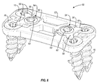
- FIG. 6 is an isometric view illustrating another example of an anti-backout device of the present invention.
- FIGS. 7 and 8 are exploded views of the anti-backout device shown in FIG. 6 .
- FIGS. 9-11 are isometric views of the anti-backout device shown in FIGS. 6-8 , illustrating the operation of the anti-backout device.
- FIGS. 12-17 show various isometric views of the surgical implant of FIG. 6 in locked and unlocked positions.
- FIG. 18 is an isometric view illustrating another example of an anti-backout device of the present invention.
- FIGS. 19 and 20 are exploded views of the anti-backout device shown in FIG. 18 .
- FIGS. 21-23 are isometric views of the anti-backout device shown in FIG. 18 , illustrating the operation of the anti-backout device.
- FIGS. 24-29 show various isometric views of the surgical implant of FIG. 18 in locked and unlocked positions.
- FIGS. 30-31 are isometric diagrams illustrating two examples of locking plates of the present invention.
- FIGS. 32-33 are isometric views showing an implant and retention devices of the present invention.
- FIG. 34 is an isometric diagram of the implant shown in FIG. 1 , installed between the end plates of two adjacent vertebrae.
- the present invention relates to locking mechanisms used with surgical implants for use in various medical applications.
- Numerous types of surgical implants use fasteners such as screws or pins to fix the implant in place.
- Examples of surgical implants that may secured using fasteners includes bone plates, spinal fusion devices, intervertebral spinal devices, artificial joints, etc.
- the present invention will be described using several examples of surgical implants, but it should be understood that locking devices of the present invention can be used with any desired implant.
- FIG. 1 is an isometric view of one example of an anti-backout device of the present invention.
- the anti-backout device is shown being used with an interbody fusion device, although the anti-backout device may be used with any desired type of surgical implant.
- FIG. 1 shows a surgical implant 10 , including a load bearing device 12 , and a retention device 14 .
- FIG. 1 also shows two bone screws 16 and an anti-backout mechanism 18 , each of which are described in more detail below.
- FIG. 2 is an exploded view of the surgical implant 10 , showing the load bearing device 12 , the retention device 14 , and the anti-backout mechanism 18 separately.
- the load bearing device 12 is a generally U-shaped device having an open end 20 .
- the open end defines an opening that allows access to the vertebrae end plates when the load bearing device is installed.
- the leading edges of the load bearing device 12 include holes 22 , which are configured to receive pins 24 extending from the retention device 14 . The pins 24 properly align the retention device 14 with the load bearing device 12 and hold the retention device 14 in a desired position, relative to the load bearing device 12 .
- two holes 34 are formed in the retention device 14 , and are adapted to received fasteners, such as bone screws, pegs, etc.
- one of the holes 34 is angled down, and the other hole 34 is angled up, such that a first fastener can be secured to the vertebra above the interbody fusion device 10 , and a second fastener can be secured to the vertebra below the interbody fusion device 10 .
- the anti-backout device 18 will work regardless of the configuration of the holes 34 , though.
- FIG. 2 illustrates details of the components of the anti-backout mechanism 18 .
- the anti-backout mechanism 18 includes a locking plate 40 .
- the plate 40 has two opposing protrusions 42 that extend outward from the plate 40 .
- a set screw 44 is configured to extend through an opening formed in the plate 40 , and thread into the retention device 14 .
- a recess 46 is formed in the retention device 14 that is adapted to receive the locking plate 40 .
- the set screw 44 includes a head 48 that will shear off when enough torque is applied by a driver. By shearing off the head 48 , the surgeon will know that the set screw 44 is tight enough, and it will reduce the profile of the fusion device 10 .
- the retention device 14 , locking plate 40 , and set screw 44 can be pre-assembled, such that a surgeon will have a single piece that is attached to the load bearing device 12 .
- the surgeon needs only to turn the set screw 44 with a driver (the example shown in FIG. 2 shows a star screwdriver, or TorxTM driver) to lock the bone screws in place.
- a driver the example shown in FIG. 2 shows a star screwdriver, or TorxTM driver
- FIGS. 3-5 are isometric views illustrating the operation of the anti-backout mechanism 18 described above.
- FIG. 3 shows the implant 10 after the bone screws have been installed. Note that the position of the protrusions 42 of the locking plate 40 are such that the openings 34 are not obstructed, allowing a surgeon to install the bone screws 16 .
- the retention device 14 can come pre-assembled with the anti-backout mechanism in the position shown in FIG. 3 . Once the bone screws are in place, the surgeon can use a driver to turn the set screw 44 .
- FIG. 4 shows the implant 10 after the set screw 44 has been turned.
- the set screw 44 is rotated clockwise which, in turn, rotates the locking plate 40 approximately 90° until the protrusions 42 obstruct the heads of the bone screws 16 .
- the recess 46 has multiple depths.
- the recess has a first depth (shown at 46 A) and a second deeper depth shown at 46 B.
- the locking plate 40 will drop from the recess 46 A and seat into the deeper recess 46 B.
- One advantage of the invention is that a surgeon will know when the locking mechanism is locked because the surgeon will feel the locking plate 40 drop into the deeper recess while turning the set screw 44 with a driver.
- the shape of the recess 46 will tend to prevent the locking plate 40 from turning the back the other way.
- the protrusions 42 prevent the screws 16 from backing out by obstructing the opening 34 .
- a gap is formed between the protrusions 42 and the heads of the screws 16 .
- the protrusions 42 may contact the screws 16 .
- the head 48 of the set screw 44 will sheer off, eliminating the need for a torque wrench. This also lessens the profile of the implant. If the implant has to be removed in the future, a surgeon can use a driver and loosen the set screw 44 until the protrusions 42 no longer obstruct the bone screws 16 .
- FIGS. 6-17 are views showing another example of an anti-backout device, or locking mechanism, of the present invention.
- the anti-backout device is shown being used with a bone plate, in this example, an anterior cervical plate.
- the anti-backout device shown in FIGS. 6-17 may also be used with any desired type of surgical implant.
- FIG. 6 is an isometric view showing a surgical implant.
- the surgical implant is an anterior cervical plate, although the anti-backout device shown in FIG. 6 may be used with any desired implant.
- FIG. 6 shows a surgical implant 50 , including a plate 52 that is configured to be positioned over one or more bones.
- FIG. 6 also shows four bone screws 16 and two anti-backout devices 54 , each of which are described in more detail below.
- the anti-backout devices 54 each include a locking plate 56 that is secured to the plate 52 by a set screw 62 .
- the set screw 62 can include a head that will shear off when enough torque is applied by a driver, as described above with respect to FIGS. 1-5 .
- Each locking plate 56 has two protrusions 58 , which are configured to prevent the bone screws 16 from backing out when the anti-backout device is in the locked position ( FIG. 6 ).
- Each locking plate 56 also has a tab 60 , which helps to stop the rotation of the locking plate 56 at the appropriate position (described below).
- FIGS. 7 and 8 are exploded views of the surgical implant 50 , showing the implant 50 ( FIG. 7 ) and the implant 50 with four bone screws 16 installed ( FIG. 8 ).
- FIGS. 7 and 8 each show the plate 52 , the locking plates 56 , and set screws 62 .
- FIG. 8 is intended to show the configurations of the bone screws 16 , relative to the plate 52 . Note, however, that during use, the locking plates 56 and set screws 62 can be pre-assembled with the plate 52 prior to the bone screws 16 being installed. This simplifies the use of the surgical implant for the surgeon.
- holes 64 are formed in the plate 52 , and are adapted to received fasteners, such as bone screws, pegs, etc.
- the holes 64 are somewhat spherical, which allows the bone screws 16 to be inserted at an angle desired by the surgeon.
- the anti-backout device 54 will work regardless of the configuration of the holes 64 and the orientation of the screws 16 , though.
- FIGS. 6-8 illustrate details the components of the anti-backout mechanism 54 .
- the two protrusions 58 extend outward from the locking plate 56 , as shown. As shown best in FIGS. 7 and 8 , the protrusions 58 are thinner than the rest of the locking plate 56 , in this example. As described below, when the locking mechanism 54 is in the locked position, the protrusions 58 will not contact the screws 16 .
- One advantage of configuring a locking mechanism such that the protrusions do not contact the screws is that it allows the screws to rotate spherically uninhibited beneath the locking mechanism (described in more detail below).
- the anti-backout device can be configured so that the protrusions do contact the screws 16 .
- the set screw 62 is configured to extend through the opening formed in the plate 56 , and thread into the plate 52 .
- a recess 66 is formed in the plate 52 that is adapted to receive its respective locking plate 56 .
- the recess 66 has two depths. In this example, the recess has a first depth (shown at 66 A) and a second deeper depth (shown at 66 B).
- the locking plate 56 will drop from the recess 66 A and seat into the deeper recess 66 B.
- One advantage of the invention is that a surgeon will know when the locking mechanism is locked because the surgeon will feel the locking plate 56 drop into the deeper recess while turning the set screw 62 with a driver.
- the plate 52 , locking plate 56 , and set screw 62 can be pre-assembled, such that a surgeon will have a single implant device that includes the entire locking mechanism, rather than separately installing a locking mechanism after the implant has been installed. Once the bone screws are installed, the surgeon needs only to turn the set screw 62 with a driver to lock the bone screws in place.
- FIGS. 9-11 are isometric views of the surgical implant and anti-backout devices of the present invention, illustrating the operation of the anti-backout mechanism described above.
- FIG. 9 shows the implant 50 , pre-assembled with anti-backout devices 54 .
- the anti-backout devices 54 are oriented in an unlocked position, with the openings 64 unobstructed.
- the locking plates 56 rest on the raised recess 66 A ( FIGS. 7-8 ).
- FIG. 10 shows the implant 10 after the bone screws 16 have been installed. Note that the position of the protrusions 58 of the locking plate 56 are such that the openings 64 are not obstructed, allowing a surgeon to install the bone screws 16 .
- FIG. 11 shows the implant 50 after the set screws 62 have been turned.
- the set screw turned the locking plate 56 about 45 degrees clockwise, until the protrusions 58 obstruct the heads of the bone screws 16 .
- the locking plate 56 is in this position, the bone screws can not come out.
- the recess has multiple depths. As the locking plate 56 is turned, the locking plate 56 will drop from the recess 66 A ( FIG. 10 ) and seat into the deeper recess 66 B ( FIG. 1 ).
- the locking plate 56 Since the locking plate 56 is seated within the deeper recess 66 B and held downward by the set screw 62 , the locking plate 56 will not turn counterclockwise unless the set screw 62 is loosened. Also, when the tab 60 drops into the deeper recess 66 B ( FIG. 1 ), it is held in a pocket, which prevents the locking plate 56 from rotating further in either direction.
- the protrusions 58 prevent the screws 16 from backing out by obstructing the openings 64 . In the example shown in FIGS. 6-11 , a gap is formed between the protrusions 58 and the heads of the screws 16 . In other examples, the protrusions 58 may contact the screws 16 .
- the set screw 62 can be tightened to a desired torque.
- a sheer head similar to the head 48 shown in FIGS. 1-4 may be used.
- FIGS. 12-17 show various isometric views of the surgical implant 50 in locked and unlocked positions.
- FIGS. 12 , 14 , and 15 show the implant 50 in an unlocked position.
- FIGS. 13 , 16 , and 17 show the implant in a locked position.
- FIGS. 12 , 14 , and 15 shows the locking plate 56 positioned on the shallower recess 66 A.
- FIGS. 13 , 16 , and 17 show the locking plate positioned on the deeper recess 66 B.
- FIG. 13 also illustrates that the bone screws 16 are allowed to rotate spherically, allowing a surgeon to install the bone screws 16 in any desired direction, within the range of movement of the screws.
- a gap 68 is maintained between the protrusions 58 and the screws 16 . This allows the screws to rotate spherically, without being inhibited by the locking mechanism.
- FIGS. 18-29 are views showing another example of an anti-backout device, or locking mechanism, of the present invention.
- the implant shown in FIGS. 18-29 is similar to the implant shown in FIGS. 6-17 , except that a single anti-backout device can be used to secure four bone screws.
- the anti-backout device is shown being used with a bone plate, in this example, an anterior cervical plate.
- the anti-backout device shown in FIGS. 18-29 may also be used with any desired type of surgical implant.
- FIG. 18 is an isometric view showing a surgical implant 70 , including a plate 72 that is configured to be positioned over one or more bones.
- FIG. 18 also shows four bone screws 16 and an anti-backout device 74 , which is described in more detail below.
- the anti-backout device 74 includes a locking plate 76 that is secured to the plate 72 by a set screw 82 . If desired, the set screw 82 can include a head that will shear off when enough torque is applied by a driver, as described above with respect to FIGS. 1-5 .
- the locking plate 76 has four protrusions 78 , which are configured to prevent the bone screws 16 from backing out when the anti-backout device is in the locked position ( FIG. 18 ).
- FIGS. 19 and 20 are exploded views of the surgical implant 70 , showing the implant 70 ( FIG. 19 ) and the implant 70 with four bone screws 16 installed ( FIG. 20 ).
- FIGS. 19 and 20 each show the plate 72 , the locking plate 76 , and set screws 82 .
- FIG. 20 is intended to show the configurations of the bone screws 16 , relative to the plate 72 . Note, however, that during use, the locking plate 76 and set screws 82 can be pre-assembled with the plate 72 prior to the bone screws 16 being installed. This simplifies the use of the surgical implant for the surgeon.
- holes 84 are formed in the plate 72 , and are adapted to received fasteners, such as bone screws, pegs, etc.
- the holes 84 are somewhat spherical, which allows the bone screws 16 to be inserted at an angle desired by the surgeon.
- the anti-backout device 74 will work regardless of the configuration of the holes 84 and the orientation of the screws 16 , though.
- FIGS. 18-20 illustrate details the components of the anti-backout mechanism 74 .
- the four protrusions 78 extend outward from the locking plate 76 , as shown. As shown best in FIGS. 19 and 20 , the protrusions 78 are thinner than the rest of the locking plate 76 , in this example. As described below, when the locking mechanism 74 is in the locked position, the protrusions 78 will not contact the screws 16 .
- One advantage of configuring a locking mechanism such that the protrusions do not contact the screws is that it allows the screws to rotate spherically uninhibited beneath the locking mechanism.
- the anti-backout device can be configured so that the protrusions do contact the screws 16 .
- the set screw 82 is configured to extend through the opening formed in the plate 76 , and thread into the plate 72 .
- a recess 86 is formed in the plate 72 that is adapted to receive its respective locking plate 76 . As shown in FIGS. 19 and 20 , the recess 86 has two depths. In this example, the recess has a first depth (shown at 86 A) and a second deeper depth (shown at 86 B). As the locking plate 76 is turned, the locking plate 76 will drop from the recess 86 A and seat into the deeper recess 86 B.
- One advantage of the invention is that a surgeon will know when the locking mechanism is locked because the surgeon will feel the locking plate 76 drop into the deeper recess while turning the set screw 82 with a driver.
- the plate 72 , locking plate 76 , and set screw 82 can be pre-assembled, such that a surgeon will have a single implant device that includes the entire locking mechanism, rather than separately installing a locking mechanism after the implant has been installed. Once the bone screws are installed, the surgeon needs only to turn the set screw 82 with a driver to lock the bone screws in place.
- FIGS. 21-23 are isometric views of the surgical implant and anti-backout device of FIGS. 18-20 , illustrating the operation of the anti-backout mechanism.
- FIG. 21 shows the implant 70 , pre-assembled with anti-backout device 74 .
- the anti-backout device 74 is oriented in an unlocked position, with the openings 84 unobstructed.
- the locking plate 76 rests on the raised recess 86 A ( FIGS. 19-20 ).
- FIG. 22 shows the implant 10 after the bone screws 16 have been installed. Note that the position of the protrusions 78 of the locking plate 76 are such that the openings 84 are not obstructed, allowing a surgeon to install the bone screws 16 .
- FIG. 23 shows the implant 70 after the set screw 82 has been turned.
- turning the set screw 82 turns the locking plate 76 about 45 degrees clockwise, until the protrusions 78 obstruct the heads of the bone screws 16 .
- the locking plate 76 is in this position, the bone screws 16 can not come out.
- the recess 86 has multiple depths. As the locking plate 76 is turned, the locking plate 76 will drop from the recess 86 A ( FIG. 22 ) and seat into the deeper recess 86 B ( FIG. 23 ).
- the locking plate 76 Since the locking plate 76 is seated within the deeper recess 86 B and held downward by the set screw 82 , the locking plate 76 will not turn counterclockwise unless the set screw 82 is loosened.
- the protrusions 78 prevent the screws 16 from backing out by obstructing the openings 84 . In the example shown in FIGS. 18-23 , a gap is formed between the protrusions 78 and the heads of the screws 16 . In other examples, the protrusions 78 may contact the screws 16 .
- the set screw 82 can be tightened to a desired torque. If desired, a sheer head, similar to the head 48 shown in FIGS. 1-4 may be used.
- FIGS. 24-29 show various isometric views of the surgical implant 70 in locked and unlocked positions.
- FIGS. 24 , 26 , and 27 show the implant 70 in an unlocked position.
- FIGS. 25 , 28 , and 29 show the implant in a locked position.
- FIGS. 24 , 26 , and 27 shows the locking plate 76 positioned on the shallower recess 86 A.
- FIGS. 25 , 28 , and 29 show the locking plate positioned on the deeper recess 86 B.
- FIGS. 30-31 are isometric diagrams illustrating two examples of locking plates of the present invention.
- FIG. 30 is an isometric diagram of the locking plate 76 shown in FIGS. 18-29 .
- the locking plate 76 has four protrusions 78 , as described above, with an opening 79 formed to receive a set screw 82 .
- the locking plate 76 has a substantially flat bottom surface 90 , which is adapted to sit on the shallow and deep recesses 86 A and 86 B (described above). When a surgeon turns the set screw, friction between the set screw and the surfaces of the opening 79 will tend to cause the locking plate 76 to turn with the set screw.
- the bottom surface 90 contacts the recess 86 A. As long as friction between the set screw 82 and the locking plate 76 is greater than the friction between the locking plate 76 and the recess 86 A, the locking plate 76 should turn with the set screw 82 .
- the locking plate 76 and/or bone plate 72 can be made of materials, or coated with materials, with a lower coefficient of friction, and visa versa.
- the bone plate and locking plate are made of Titanium. Another design consideration that affects the amount of friction between the locking plate and bone plate is the amount of surface area of the locking plate that contacts the recess 86 A.
- FIG. 31 is an isometric diagram of a locking plate 77 having bottom surface 91 that has less surface area compared to the bottom surface 90 of the locking plate 76 shown in FIG. 30 . Since there will be less surface area contacting the recess 86 A, there will be less friction, and the locking plate 77 will turn more easily than the locking plate 76 shown in FIG. 30 . Alternately, the surface area of the recess 86 A could be reduced to reduce the friction between the locking plate and the bone plate. In another example, the bottom surface of the locking plate and/or the surface of the bone plate can be angled such that the locking plate will turn easier, relative to the bone plate. It can be seen that, the resistance experienced when rotating a locking plate can be controlled by configuring various aspects of the locking plate and bone plate.
- anti-backout mechanisms are also possible within the spirit and scope of the invention.
- exemplary the anti-backout mechanisms described above can be used in combination with each other.
- a locking mechanism 54 e.g., FIG. 6
- a locking mechanism 74 e.g., FIG. 18
- a locking mechanism of the present invention can be pre-assembled with an implant (e.g., FIGS. 1 , 9 , 21 ), making the use of the implant and locking mechanism easier.
- an implant and locking mechanism it will be desired that the locking mechanism does not rotate during transit or storage.
- FIGS. 32-33 are isometric views showing an implant and retention devices of the present invention.
- FIG. 32 is an exploded isometric view showing an implant 50 , as described above.
- FIG. 32 also shows two retention devices 100 , which are configured to keep the implant 50 in an assembled position by preventing the set screws from turning prior to the use of the implant. When a surgeon is ready to install the implant, the surgeon can simply remove the retention devices 100 from the implant 50 .
- the retention device 100 has a plug 102 shaped to fit into the star driver head (e.g., a TorxTM head) of the set screw 62 .
- star driver head e.g., a TorxTM head
- FIG. 33 shows the implant 50 and retention devices 100 in an assembled view.
- the plug 102 is configured to fit into one of the opening 64 formed in the plate 52 .
- the retention device can engage other openings or surfaces of the implant.
- the pin 104 can be configured like the plug 102 and fit into the star head of the other set screw, thus only requiring only one retention device 100 per implant.
- FIG. 34 is an isometric diagram of the implant shown in FIG. 1 , installed between the end plates of two adjacent vertebrae. As shown, when installed, one bone screw 16 is screwed into one vertebrae, and the other bone screw 16 is screwed into the other vertebrae. In the example shown in FIG. 34 , the left screw 16 is angled upward and screwed into the upper vertebrae and right screw 16 is angled downward and screwed into the lower vertebrae. Although the two bone screws 16 are secured to two separate bones, the locking mechanism 18 is capable of locking both screws 16 .
Abstract
Description
Claims (3)
Priority Applications (2)
| Application Number | Priority Date | Filing Date | Title |
|---|---|---|---|
| US12/044,186 US8882813B2 (en) | 2007-10-19 | 2008-03-07 | Locking mechanisms and associated methods |
| US13/200,911 US8597353B2 (en) | 2007-06-06 | 2011-10-04 | Interbody fusion device and associated methods |
Applications Claiming Priority (2)
| Application Number | Priority Date | Filing Date | Title |
|---|---|---|---|
| US98135807P | 2007-10-19 | 2007-10-19 | |
| US12/044,186 US8882813B2 (en) | 2007-10-19 | 2008-03-07 | Locking mechanisms and associated methods |
Related Child Applications (1)
| Application Number | Title | Priority Date | Filing Date |
|---|---|---|---|
| US12/018,703 Continuation-In-Part US8795373B2 (en) | 2007-06-06 | 2008-01-23 | Interbody fusion device, integral retention device, and associated methods |
Publications (2)
| Publication Number | Publication Date |
|---|---|
| US20090105831A1 US20090105831A1 (en) | 2009-04-23 |
| US8882813B2 true US8882813B2 (en) | 2014-11-11 |
Family
ID=40564281
Family Applications (1)
| Application Number | Title | Priority Date | Filing Date |
|---|---|---|---|
| US12/044,186 Active 2031-07-24 US8882813B2 (en) | 2007-06-06 | 2008-03-07 | Locking mechanisms and associated methods |
Country Status (1)
| Country | Link |
|---|---|
| US (1) | US8882813B2 (en) |
Cited By (26)
| Publication number | Priority date | Publication date | Assignee | Title |
|---|---|---|---|---|
| US20150216674A1 (en) * | 2011-04-29 | 2015-08-06 | Life Spine, Inc. | Spinal interbody implant with bone screw retention |
| US9364340B2 (en) * | 2013-03-05 | 2016-06-14 | Globus Medical, Inc. | Low profile plate |
| US20160324657A1 (en) * | 2011-11-17 | 2016-11-10 | Zimmer Biomet Spine, Inc. | Modular anchor bone fusion cage |
| US9504584B1 (en) | 2011-01-28 | 2016-11-29 | Nuvasive, Inc. | Spinal fusion implant and related methods |
| US9522069B1 (en) * | 2007-07-02 | 2016-12-20 | Theken Spine, Llc | Spinal cage having deployable member |
| USD779065S1 (en) | 2014-10-08 | 2017-02-14 | Nuvasive, Inc. | Anterior cervical bone plate |
| US9848998B2 (en) | 2005-04-12 | 2017-12-26 | Nathan C. Moskowitz | Bi-directional fixating transvertebral body screws and posterior cervical and lumbar interarticulating joint calibrated stapling devices for spinal fusion |
| US9877759B2 (en) | 2014-02-06 | 2018-01-30 | Life Spine, Inc. | Foot implant for bone fixation |
| US9889014B2 (en) | 2014-02-06 | 2018-02-13 | Life Spine, Inc. | Implant for bone fixation |
| US10076367B2 (en) | 2005-04-12 | 2018-09-18 | Moskowitz Family Llc | Bi-directional fixating transvertebral body screws, zero-profile horizontal intervertebral miniplates, total intervertebral body fusion devices, and posterior motion-calibrating interarticulating joint stapling device for spinal fusion |
| US10342674B2 (en) | 2007-07-02 | 2019-07-09 | Theken Spine, Llc | Spinal cage having deployable member |
| US10376383B2 (en) | 2005-04-12 | 2019-08-13 | Moskowitz Family Llc | Bi-directional fixating/locking transvertebral body screw/intervertebral cage stand-alone constructs |
| US10492912B2 (en) | 2017-08-18 | 2019-12-03 | Innovasis, Inc. | Interbody spinal fusion implant having locking elements with lateral displacement |
| US10555764B2 (en) | 2017-08-22 | 2020-02-11 | Innovasis, Inc. | Interbody spinal fusion implant having locking elements that outwardly displace for locking |
| US11298244B2 (en) * | 2019-01-31 | 2022-04-12 | K2M, Inc. | Interbody implants and instrumentation |
| US11376134B1 (en) | 2020-11-05 | 2022-07-05 | Warsaw Orthopedic, Inc. | Dual expanding spinal implant, system, and method of use |
| US11395743B1 (en) | 2021-05-04 | 2022-07-26 | Warsaw Orthopedic, Inc. | Externally driven expandable interbody and related methods |
| US11517363B2 (en) | 2020-11-05 | 2022-12-06 | Warsaw Orthopedic, Inc. | Screw driver and complimentary screws |
| US11517443B2 (en) | 2020-11-05 | 2022-12-06 | Warsaw Orthopedic, Inc. | Dual wedge expandable implant, system and method of use |
| US11534307B2 (en) | 2019-09-16 | 2022-12-27 | K2M, Inc. | 3D printed cervical standalone implant |
| US11612499B2 (en) | 2021-06-24 | 2023-03-28 | Warsaw Orthopedic, Inc. | Expandable interbody implant |
| US11638653B2 (en) | 2020-11-05 | 2023-05-02 | Warsaw Orthopedic, Inc. | Surgery instruments with a movable handle |
| US11806250B2 (en) | 2018-02-22 | 2023-11-07 | Warsaw Orthopedic, Inc. | Expandable spinal implant system and method of using same |
| US11833059B2 (en) | 2020-11-05 | 2023-12-05 | Warsaw Orthopedic, Inc. | Expandable inter-body device, expandable plate system, and associated methods |
| US11850163B2 (en) | 2022-02-01 | 2023-12-26 | Warsaw Orthopedic, Inc. | Interbody implant with adjusting shims |
| US11903849B2 (en) | 2005-04-12 | 2024-02-20 | Moskowitz Family Llc | Intervertebral implant and tool assembly |
Families Citing this family (96)
| Publication number | Priority date | Publication date | Assignee | Title |
|---|---|---|---|---|
| FR2897259B1 (en) | 2006-02-15 | 2008-05-09 | Ldr Medical Soc Par Actions Si | INTERSOMATIC TRANSFORAMINAL CAGE WITH INTERBREBAL FUSION GRAFT AND CAGE IMPLANTATION INSTRUMENT |
| FR2824261B1 (en) | 2001-05-04 | 2004-05-28 | Ldr Medical | INTERVERTEBRAL DISC PROSTHESIS AND IMPLEMENTATION METHOD AND TOOLS |
| FR2827156B1 (en) | 2001-07-13 | 2003-11-14 | Ldr Medical | VERTEBRAL CAGE DEVICE WITH MODULAR FASTENING |
| FR2846550B1 (en) | 2002-11-05 | 2006-01-13 | Ldr Medical | INTERVERTEBRAL DISC PROSTHESIS |
| ES2547532T3 (en) | 2004-02-04 | 2015-10-07 | Ldr Medical | Intervertebral disc prosthesis |
| FR2865629B1 (en) | 2004-02-04 | 2007-01-26 | Ldr Medical | INTERVERTEBRAL DISC PROSTHESIS |
| FR2869528B1 (en) | 2004-04-28 | 2007-02-02 | Ldr Medical | INTERVERTEBRAL DISC PROSTHESIS |
| EP1814474B1 (en) | 2004-11-24 | 2011-09-14 | Samy Abdou | Devices for inter-vertebral orthopedic device placement |
| FR2879436B1 (en) | 2004-12-22 | 2007-03-09 | Ldr Medical | INTERVERTEBRAL DISC PROSTHESIS |
| US7704279B2 (en) | 2005-04-12 | 2010-04-27 | Moskowitz Mosheh T | Bi-directional fixating transvertebral body screws, zero-profile horizontal intervertebral miniplates, expansile intervertebral body fusion devices, and posterior motion-calibrating interarticulating joint stapling device for spinal fusion |
| US9888918B2 (en) | 2005-04-12 | 2018-02-13 | Nathan C. Moskowitz | Horizontal-transvertebral curvilinear nail-screws with inter-locking rigid or jointed flexible rods for spinal fusion |
| US9744052B2 (en) | 2005-04-12 | 2017-08-29 | Nathan C. Moskowitz | Bi-directional fixating/locking transvertebral body screw/intervertebral cage stand-alone constructs |
| US9848993B2 (en) | 2005-04-12 | 2017-12-26 | Nathan C. Moskowitz | Zero-profile expandable intervertebral spacer devices for distraction and spinal fusion and a universal tool for their placement and expansion |
| US7972363B2 (en) * | 2005-04-12 | 2011-07-05 | Moskowitz Ahmnon D | Bi-directional fixating/locking transvertebral body screw/intervertebral cage stand-alone constructs and posterior cervical and lumbar interarticulating joint stapling guns and devices for spinal fusion |
| US9532821B2 (en) | 2005-04-12 | 2017-01-03 | Nathan C. Moskowitz | Bi-directional fixating/locking transvertebral body screw/intervertebral cage stand-alone constructs with vertical hemi-bracket screw locking mechanism |
| US9675385B2 (en) | 2005-04-12 | 2017-06-13 | Nathan C. Moskowitz | Spinous process staple with interdigitating-interlocking hemi-spacers for adjacent spinous process separation and distraction |
| FR2891135B1 (en) | 2005-09-23 | 2008-09-12 | Ldr Medical Sarl | INTERVERTEBRAL DISC PROSTHESIS |
| FR2893838B1 (en) | 2005-11-30 | 2008-08-08 | Ldr Medical Soc Par Actions Si | PROSTHESIS OF INTERVERTEBRAL DISC AND INSTRUMENTATION OF INSERTION OF THE PROSTHESIS BETWEEN VERTEBRATES |
| US7854765B2 (en) | 2006-04-20 | 2010-12-21 | Moskowitz Mosheh T | Electronically controlled artificial intervertebral disc with motor assisted actuation systems |
| US9039768B2 (en) | 2006-12-22 | 2015-05-26 | Medos International Sarl | Composite vertebral spacers and instrument |
| US8465546B2 (en) | 2007-02-16 | 2013-06-18 | Ldr Medical | Intervertebral disc prosthesis insertion assemblies |
| US8273127B2 (en) | 2007-06-06 | 2012-09-25 | Spinesmith Partners, L.P. | Interbody fusion device and associated methods |
| FR2916956B1 (en) | 2007-06-08 | 2012-12-14 | Ldr Medical | INTERSOMATIC CAGE, INTERVERTEBRAL PROSTHESIS, ANCHORING DEVICE AND IMPLANTATION INSTRUMENTATION |
| US20090248092A1 (en) | 2008-03-26 | 2009-10-01 | Jonathan Bellas | Posterior Intervertebral Disc Inserter and Expansion Techniques |
| US8328872B2 (en) * | 2008-09-02 | 2012-12-11 | Globus Medical, Inc. | Intervertebral fusion implant |
| WO2010096773A1 (en) * | 2009-02-20 | 2010-08-26 | Spartan Cage Holding, Llc | Interbody fusion system with intervertebral implant retention assembly |
| US9526620B2 (en) | 2009-03-30 | 2016-12-27 | DePuy Synthes Products, Inc. | Zero profile spinal fusion cage |
| US9408715B2 (en) | 2009-04-15 | 2016-08-09 | DePuy Synthes Products, Inc. | Arcuate fixation member |
| US8641766B2 (en) | 2009-04-15 | 2014-02-04 | DePuy Synthes Products, LLC | Arcuate fixation member |
| US10842642B2 (en) | 2009-04-16 | 2020-11-24 | Nuvasive, Inc. | Methods and apparatus of performing spine surgery |
| US9095444B2 (en) | 2009-07-24 | 2015-08-04 | Warsaw Orthopedic, Inc. | Implant with an interference fit fastener |
| BR112012005663A2 (en) | 2009-09-17 | 2021-07-27 | Synthes Gmbh | intervertebral implant with expandable bone fixation limbs |
| US8740983B1 (en) | 2009-11-11 | 2014-06-03 | Nuvasive, Inc. | Spinal fusion implants and related methods |
| US8840668B1 (en) | 2009-11-11 | 2014-09-23 | Nuvasive, Inc. | Spinal implants, instruments and related methods |
| US8764806B2 (en) | 2009-12-07 | 2014-07-01 | Samy Abdou | Devices and methods for minimally invasive spinal stabilization and instrumentation |
| US9393129B2 (en) | 2009-12-10 | 2016-07-19 | DePuy Synthes Products, Inc. | Bellows-like expandable interbody fusion cage |
| US9833331B2 (en) | 2009-12-31 | 2017-12-05 | Ldr Medical | Anchoring device and system for an intervertebral implant, intervertebral implant and implantation instrument |
| US9155631B2 (en) | 2010-04-08 | 2015-10-13 | Globus Medical Inc. | Intervertbral implant |
| US8282683B2 (en) * | 2010-04-12 | 2012-10-09 | Globus Medical, Inc. | Expandable vertebral implant |
| US8425569B2 (en) * | 2010-05-19 | 2013-04-23 | Transcorp, Inc. | Implantable vertebral frame systems and related methods for spinal repair |
| US20120078372A1 (en) | 2010-09-23 | 2012-03-29 | Thomas Gamache | Novel implant inserter having a laterally-extending dovetail engagement feature |
| US20120078373A1 (en) | 2010-09-23 | 2012-03-29 | Thomas Gamache | Stand alone intervertebral fusion device |
| US11529241B2 (en) | 2010-09-23 | 2022-12-20 | DePuy Synthes Products, Inc. | Fusion cage with in-line single piece fixation |
| US20120209385A1 (en) * | 2011-02-15 | 2012-08-16 | Joshua Michael Aferzon | Anterior intervertebral fusion with fixation system, device and method |
| US8454694B2 (en) * | 2011-03-03 | 2013-06-04 | Warsaw Orthopedic, Inc. | Interbody device and plate for spinal stabilization and instruments for positioning same |
| EP2696813B1 (en) * | 2011-04-15 | 2020-03-18 | Synthes GmbH | Fixation assembly |
| US10166115B2 (en) * | 2011-07-12 | 2019-01-01 | Spinesmith Partners, L.P. | Interbody fusion device |
| US9724132B2 (en) | 2011-08-31 | 2017-08-08 | DePuy Synthes Products, Inc. | Devices and methods for cervical lateral fixation |
| US9248028B2 (en) | 2011-09-16 | 2016-02-02 | DePuy Synthes Products, Inc. | Removable, bone-securing cover plate for intervertebral fusion cage |
| US9539109B2 (en) | 2011-09-16 | 2017-01-10 | Globus Medical, Inc. | Low profile plate |
| US9237957B2 (en) * | 2011-09-16 | 2016-01-19 | Globus Medical, Inc. | Low profile plate |
| US8845728B1 (en) | 2011-09-23 | 2014-09-30 | Samy Abdou | Spinal fixation devices and methods of use |
| US9198764B2 (en) | 2012-01-31 | 2015-12-01 | Blackstone Medical, Inc. | Intervertebral disc prosthesis and method |
| US20130226240A1 (en) | 2012-02-22 | 2013-08-29 | Samy Abdou | Spinous process fixation devices and methods of use |
| FR2987256B1 (en) | 2012-02-24 | 2014-08-08 | Ldr Medical | ANCHORING DEVICE FOR INTERVERTEBRAL IMPLANT, INTERVERTEBRAL IMPLANT AND IMPLANTATION INSTRUMENTATION |
| US9271836B2 (en) | 2012-03-06 | 2016-03-01 | DePuy Synthes Products, Inc. | Nubbed plate |
| US9693876B1 (en) * | 2012-03-30 | 2017-07-04 | Ali H. MESIWALA | Spinal fusion implant and related methods |
| US9326861B2 (en) | 2012-08-03 | 2016-05-03 | Globus Medical, Inc. | Stabilizing joints |
| US9198767B2 (en) | 2012-08-28 | 2015-12-01 | Samy Abdou | Devices and methods for spinal stabilization and instrumentation |
| US9320617B2 (en) | 2012-10-22 | 2016-04-26 | Cogent Spine, LLC | Devices and methods for spinal stabilization and instrumentation |
| US10182921B2 (en) | 2012-11-09 | 2019-01-22 | DePuy Synthes Products, Inc. | Interbody device with opening to allow packing graft and other biologics |
| US20140148860A1 (en) * | 2012-11-27 | 2014-05-29 | Jim A. Rinner | Expanding Blade Screw Retention System |
| US9693874B2 (en) | 2013-03-15 | 2017-07-04 | Blackstone Medical, Inc. | Composite spinal interbody device and method |
| FR3005569B1 (en) | 2013-05-16 | 2021-09-03 | Ldr Medical | VERTEBRAL IMPLANT, VERTEBRAL IMPLANT FIXATION DEVICE AND IMPLANTATION INSTRUMENTATION |
| CN105578994B (en) * | 2013-07-24 | 2019-08-02 | 雷诺维斯外科技术公司 | Combine the surgical implant device of porous surface |
| JP6419181B2 (en) | 2013-07-24 | 2018-11-07 | レノビス サージカル テクノロジーズ,インコーポレイテッド | Surgical implant device incorporating a porous surface |
| EP3052037B1 (en) * | 2013-10-02 | 2022-08-24 | Kyocera Medical Technologies, Inc. | Surgical implant devices incorporating porous surfaces and a locking plate |
| WO2015051080A1 (en) * | 2013-10-02 | 2015-04-09 | Renovis Surgical Technologies, Inc. | Surgical implant devices incorporating porous surfaces and a locking plate |
| US9283091B2 (en) * | 2013-10-07 | 2016-03-15 | Warsaw Orthopedic, Inc. | Spinal implant system and method |
| US9918848B2 (en) * | 2013-10-07 | 2018-03-20 | Warsaw Orthopedic, Inc. | Spinal implant system and method |
| USD745159S1 (en) | 2013-10-10 | 2015-12-08 | Nuvasive, Inc. | Intervertebral implant |
| FR3016793B1 (en) | 2014-01-30 | 2021-05-07 | Ldr Medical | ANCHORING DEVICE FOR SPINAL IMPLANT, SPINAL IMPLANT AND IMPLANTATION INSTRUMENTATION |
| US10426630B2 (en) | 2014-02-12 | 2019-10-01 | K2M, Inc. | Spinal implant |
| FR3020756B1 (en) | 2014-05-06 | 2022-03-11 | Ldr Medical | VERTEBRAL IMPLANT, VERTEBRAL IMPLANT FIXATION DEVICE AND IMPLANT INSTRUMENTATION |
| US20160151166A1 (en) * | 2014-07-01 | 2016-06-02 | Alliance Partners, Llc | Low profile standalone cervical interbody with screw locking clips and method of using same |
| USD858769S1 (en) | 2014-11-20 | 2019-09-03 | Nuvasive, Inc. | Intervertebral implant |
| US9381093B1 (en) * | 2015-02-09 | 2016-07-05 | Alliance Partners, Llc | Locking device for fixation mechanism of medical implant |
| US10034768B2 (en) * | 2015-09-02 | 2018-07-31 | Globus Medical, Inc. | Implantable systems, devices and related methods |
| US10130402B2 (en) | 2015-09-25 | 2018-11-20 | Globus Medical, Inc. | Bone fixation devices having a locking feature |
| US10857003B1 (en) | 2015-10-14 | 2020-12-08 | Samy Abdou | Devices and methods for vertebral stabilization |
| US20200000595A1 (en) | 2016-06-07 | 2020-01-02 | HD LifeSciences LLC | High X-Ray Lucency Lattice Structures |
| US9918750B2 (en) * | 2016-08-04 | 2018-03-20 | Osseus Fusion Systems, Llc | Method, system, and apparatus for temporary anterior cervical plate fixation |
| US10744000B1 (en) | 2016-10-25 | 2020-08-18 | Samy Abdou | Devices and methods for vertebral bone realignment |
| US10973648B1 (en) | 2016-10-25 | 2021-04-13 | Samy Abdou | Devices and methods for vertebral bone realignment |
| USD814037S1 (en) * | 2017-01-17 | 2018-03-27 | Paragon 28, Inc. | Spacer wedge |
| WO2018152077A1 (en) | 2017-02-14 | 2018-08-23 | HD LifeSciences LLC | High x-ray lucency lattice structures and variably x-ray licent markers |
| US10888429B2 (en) | 2017-04-01 | 2021-01-12 | HD LifeSciences LLC | Three-dimensional lattice structures for implants |
| US10940016B2 (en) | 2017-07-05 | 2021-03-09 | Medos International Sarl | Expandable intervertebral fusion cage |
| US20190133778A1 (en) * | 2017-11-03 | 2019-05-09 | Terry Johnston | Spinal lateral implant |
| JP2021531894A (en) * | 2018-07-26 | 2021-11-25 | エイチディー ライフサイエンシズ エルエルシーHd Lifesciences Llc | Dynamic implant fixation plate |
| US11179248B2 (en) | 2018-10-02 | 2021-11-23 | Samy Abdou | Devices and methods for spinal implantation |
| US11071629B2 (en) * | 2018-10-13 | 2021-07-27 | Neurostructures Inc. | Interbody spacer |
| US11497617B2 (en) | 2019-01-16 | 2022-11-15 | Nanohive Medical Llc | Variable depth implants |
| US11382761B2 (en) | 2020-04-11 | 2022-07-12 | Neurostructures, Inc. | Expandable interbody spacer |
| US11304817B2 (en) | 2020-06-05 | 2022-04-19 | Neurostructures, Inc. | Expandable interbody spacer |
| US11717419B2 (en) | 2020-12-10 | 2023-08-08 | Neurostructures, Inc. | Expandable interbody spacer |
Citations (49)
| Publication number | Priority date | Publication date | Assignee | Title |
|---|---|---|---|---|
| US2825329A (en) | 1953-02-04 | 1958-03-04 | Orville S Caesar | Internal fixation of fractures |
| US3528085A (en) | 1968-03-22 | 1970-09-08 | Walker Reynolds Jr | Bone compression plate |
| US3534731A (en) | 1967-08-18 | 1970-10-20 | Jean Nicolas Muller | Means for joining parts of fractured bones |
| US3842825A (en) | 1973-11-12 | 1974-10-22 | R Wagner | Hip fixation device |
| US4013071A (en) | 1974-11-11 | 1977-03-22 | Lior Rosenberg | Fasteners particularly useful as orthopedic screws |
| US4388921A (en) | 1980-05-28 | 1983-06-21 | Institut Straumann Ag | Device comprising a plate and screws for fastening a plate to a bone |
| US4432358A (en) | 1982-01-22 | 1984-02-21 | Fixel Irving E | Compression hip screw apparatus |
| US4488543A (en) | 1982-01-19 | 1984-12-18 | Tornier S.A. France | Device for osteosynthesis of fractures of the extremities of the femur |
| US4794918A (en) | 1985-05-06 | 1989-01-03 | Dietmar Wolter | Bone plate arrangement |
| EP0455255A1 (en) | 1990-05-04 | 1991-11-06 | Witold Ramotowski | A plate-type bone stabilizer |
| US5127914A (en) | 1989-02-10 | 1992-07-07 | Calderale Pasquale M | Osteosynthesis means for the connection of bone fracture segments |
| EP0599640A1 (en) | 1992-11-25 | 1994-06-01 | CODMAN & SHURTLEFF INC. | Osteosynthesis plate system |
| US5364399A (en) | 1993-02-05 | 1994-11-15 | Danek Medical, Inc. | Anterior cervical plating system |
| US5534027A (en) | 1993-06-21 | 1996-07-09 | Zimmer, Inc. | Method for providing a barrier to the advancement of wear debris in an orthopaedic implant assembly |
| US5569250A (en) * | 1994-03-01 | 1996-10-29 | Sarver; David R. | Method and apparatus for securing adjacent bone portions |
| US5681311A (en) | 1994-09-15 | 1997-10-28 | Smith & Nephew, Inc. | Osteosynthesis apparatus |
| US5713900A (en) | 1996-05-31 | 1998-02-03 | Acromed Corporation | Apparatus for retaining bone portions in a desired spatial relationship |
| US5800433A (en) | 1996-05-31 | 1998-09-01 | Acromed Corporation | Spinal column retaining apparatus |
| US5888223A (en) | 1995-12-08 | 1999-03-30 | Bray, Jr.; Robert S. | Anterior stabilization device |
| US5951558A (en) * | 1998-04-22 | 1999-09-14 | Fiz; Daniel | Bone fixation device |
| US6139550A (en) | 1997-02-11 | 2000-10-31 | Michelson; Gary K. | Skeletal plating system |
| US6152927A (en) | 1997-05-15 | 2000-11-28 | Sdgi Holdings, Inc. | Anterior cervical plating system |
| US6193721B1 (en) | 1997-02-11 | 2001-02-27 | Gary K. Michelson | Multi-lock anterior cervical plating system |
| US6228087B1 (en) | 2000-01-31 | 2001-05-08 | Depuy Orthopaedics, Inc. | Fixation member for treating orthopedic fractures |
| US6235034B1 (en) | 1997-10-24 | 2001-05-22 | Robert S. Bray | Bone plate and bone screw guide mechanism |
| US6306139B1 (en) | 1998-10-19 | 2001-10-23 | Scint'x | Intervertebral connection device with an anti-extraction device to prevent extraction of anchoring screws |
| US6361537B1 (en) | 2001-05-18 | 2002-03-26 | Cinci M. Anderson | Surgical plate with pawl and process for repair of a broken bone |
| US6413259B1 (en) | 2000-12-14 | 2002-07-02 | Blackstone Medical, Inc | Bone plate assembly including a screw retaining member |
| US6503250B2 (en) | 2000-11-28 | 2003-01-07 | Kamaljit S. Paul | Bone support assembly |
| US20030060828A1 (en) | 2001-06-06 | 2003-03-27 | Michelson Gary K. | Dynamic multilock anterior cervical plate system having non-detachably fastened and moveable segments, instrumentation, and method for installation thereof |
| US6602255B1 (en) | 2000-06-26 | 2003-08-05 | Stryker Spine | Bone screw retaining system |
| US6652525B1 (en) | 1998-04-30 | 2003-11-25 | Sofamor S.N.C. | Anterior implant for the spine |
| US6730127B2 (en) * | 2000-07-10 | 2004-05-04 | Gary K. Michelson | Flanged interbody spinal fusion implants |
| US6755833B1 (en) | 2001-12-14 | 2004-06-29 | Kamaljit S. Paul | Bone support assembly |
| US6793658B2 (en) | 2001-04-06 | 2004-09-21 | Society De Fabrication De Material Orthopedique, S.A. | Anterior plating system and method |
| US20050021032A1 (en) | 2003-07-22 | 2005-01-27 | Ja-Kyo Koo | Cervical spine fixator and screwdriver used therefor |
| US20050101960A1 (en) | 2001-04-03 | 2005-05-12 | Vincent Fiere | Stabilised interbody fusion system for vertebrae |
| US6893444B2 (en) | 2000-02-01 | 2005-05-17 | Hand Innovations, Llc | Bone fracture fixation systems with both multidirectional and unidirectional stabilization pegs |
| US6945973B2 (en) | 2003-05-01 | 2005-09-20 | Nuvasive, Inc. | Slidable bone plate system |
| US6972019B2 (en) | 2001-01-23 | 2005-12-06 | Michelson Gary K | Interbody spinal implant with trailing end adapted to receive bone screws |
| US7025769B1 (en) | 2002-06-04 | 2006-04-11 | Nuvasive, Inc. | Surgical fixation system and related methods |
| US20060085071A1 (en) | 2003-02-06 | 2006-04-20 | Beat Lechmann | Intervertebral implant |
| US7033394B2 (en) | 1999-05-05 | 2006-04-25 | Sdgi Holdings, Inc. | Interbody spinal fusion implants with end cap for locking vertebral body penetrating members |
| US7041105B2 (en) | 2001-06-06 | 2006-05-09 | Sdgi Holdings, Inc. | Dynamic, modular, multilock anterior cervical plate system having detachably fastened assembleable and moveable segments |
| US20060149253A1 (en) | 2005-01-06 | 2006-07-06 | Doubler Robert L | Spinal plate with internal screw locks |
| US20060149255A1 (en) | 2005-01-06 | 2006-07-06 | Doubler Robert L | Spinal implant kit |
| US20060200146A1 (en) | 2005-01-06 | 2006-09-07 | Doubler Robert L | Spinal plate with screw locks and cam locks |
| US20060229620A1 (en) | 2005-03-03 | 2006-10-12 | Accin Corporation | Method and apparatus for providing a retainer for a bone stabilization device |
| US20080306596A1 (en) | 2007-06-06 | 2008-12-11 | Jones Robert J | Interbody fusion device and associated methods |
-
2008
- 2008-03-07 US US12/044,186 patent/US8882813B2/en active Active
Patent Citations (62)
| Publication number | Priority date | Publication date | Assignee | Title |
|---|---|---|---|---|
| US2825329A (en) | 1953-02-04 | 1958-03-04 | Orville S Caesar | Internal fixation of fractures |
| US3534731A (en) | 1967-08-18 | 1970-10-20 | Jean Nicolas Muller | Means for joining parts of fractured bones |
| US3528085A (en) | 1968-03-22 | 1970-09-08 | Walker Reynolds Jr | Bone compression plate |
| US3842825A (en) | 1973-11-12 | 1974-10-22 | R Wagner | Hip fixation device |
| US4013071A (en) | 1974-11-11 | 1977-03-22 | Lior Rosenberg | Fasteners particularly useful as orthopedic screws |
| US4388921A (en) | 1980-05-28 | 1983-06-21 | Institut Straumann Ag | Device comprising a plate and screws for fastening a plate to a bone |
| US4488543A (en) | 1982-01-19 | 1984-12-18 | Tornier S.A. France | Device for osteosynthesis of fractures of the extremities of the femur |
| US4432358A (en) | 1982-01-22 | 1984-02-21 | Fixel Irving E | Compression hip screw apparatus |
| US4794918A (en) | 1985-05-06 | 1989-01-03 | Dietmar Wolter | Bone plate arrangement |
| US5127914A (en) | 1989-02-10 | 1992-07-07 | Calderale Pasquale M | Osteosynthesis means for the connection of bone fracture segments |
| EP0455255A1 (en) | 1990-05-04 | 1991-11-06 | Witold Ramotowski | A plate-type bone stabilizer |
| EP0599640A1 (en) | 1992-11-25 | 1994-06-01 | CODMAN & SHURTLEFF INC. | Osteosynthesis plate system |
| US5549612A (en) | 1992-11-25 | 1996-08-27 | Codman & Shurtleff, Inc. | Osteosynthesis plate system |
| US5616144A (en) | 1992-11-25 | 1997-04-01 | Codman & Shurtleff, Inc. | Osteosynthesis plate system |
| US5364399A (en) | 1993-02-05 | 1994-11-15 | Danek Medical, Inc. | Anterior cervical plating system |
| US5534027A (en) | 1993-06-21 | 1996-07-09 | Zimmer, Inc. | Method for providing a barrier to the advancement of wear debris in an orthopaedic implant assembly |
| US5569250A (en) * | 1994-03-01 | 1996-10-29 | Sarver; David R. | Method and apparatus for securing adjacent bone portions |
| US5681311A (en) | 1994-09-15 | 1997-10-28 | Smith & Nephew, Inc. | Osteosynthesis apparatus |
| US5888223A (en) | 1995-12-08 | 1999-03-30 | Bray, Jr.; Robert S. | Anterior stabilization device |
| US5713900A (en) | 1996-05-31 | 1998-02-03 | Acromed Corporation | Apparatus for retaining bone portions in a desired spatial relationship |
| US5800433A (en) | 1996-05-31 | 1998-09-01 | Acromed Corporation | Spinal column retaining apparatus |
| US20020128655A1 (en) | 1997-02-11 | 2002-09-12 | Michelson Gary K. | Segmentable skeletal plating system |
| US6139550A (en) | 1997-02-11 | 2000-10-31 | Michelson; Gary K. | Skeletal plating system |
| US6936051B2 (en) | 1997-02-11 | 2005-08-30 | Gary K. Michelson | Multilock anterior cervical plating system |
| US6193721B1 (en) | 1997-02-11 | 2001-02-27 | Gary K. Michelson | Multi-lock anterior cervical plating system |
| US6936050B2 (en) | 1997-02-11 | 2005-08-30 | Gary K. Michelson | Multilock anterior cervical plating system |
| US6620163B1 (en) | 1997-02-11 | 2003-09-16 | Gary K. Michelson | Anterior cervical plating system and bone screw |
| US6592586B1 (en) | 1997-02-11 | 2003-07-15 | Gary K. Michelson | Single-lock anterior cervical plating system |
| US6383186B1 (en) | 1997-02-11 | 2002-05-07 | Gary K. Michelson | Single-lock skeletal plating system |
| US6152927A (en) | 1997-05-15 | 2000-11-28 | Sdgi Holdings, Inc. | Anterior cervical plating system |
| US6235034B1 (en) | 1997-10-24 | 2001-05-22 | Robert S. Bray | Bone plate and bone screw guide mechanism |
| US5951558A (en) * | 1998-04-22 | 1999-09-14 | Fiz; Daniel | Bone fixation device |
| US6652525B1 (en) | 1998-04-30 | 2003-11-25 | Sofamor S.N.C. | Anterior implant for the spine |
| US6306139B1 (en) | 1998-10-19 | 2001-10-23 | Scint'x | Intervertebral connection device with an anti-extraction device to prevent extraction of anchoring screws |
| US7033394B2 (en) | 1999-05-05 | 2006-04-25 | Sdgi Holdings, Inc. | Interbody spinal fusion implants with end cap for locking vertebral body penetrating members |
| US6228087B1 (en) | 2000-01-31 | 2001-05-08 | Depuy Orthopaedics, Inc. | Fixation member for treating orthopedic fractures |
| US6893444B2 (en) | 2000-02-01 | 2005-05-17 | Hand Innovations, Llc | Bone fracture fixation systems with both multidirectional and unidirectional stabilization pegs |
| US6602255B1 (en) | 2000-06-26 | 2003-08-05 | Stryker Spine | Bone screw retaining system |
| US6730127B2 (en) * | 2000-07-10 | 2004-05-04 | Gary K. Michelson | Flanged interbody spinal fusion implants |
| US20030149434A1 (en) | 2000-11-28 | 2003-08-07 | Paul Kamaljit S. | Bone support assembly |
| US6503250B2 (en) | 2000-11-28 | 2003-01-07 | Kamaljit S. Paul | Bone support assembly |
| US6413259B1 (en) | 2000-12-14 | 2002-07-02 | Blackstone Medical, Inc | Bone plate assembly including a screw retaining member |
| US6972019B2 (en) | 2001-01-23 | 2005-12-06 | Michelson Gary K | Interbody spinal implant with trailing end adapted to receive bone screws |
| US7172627B2 (en) | 2001-04-03 | 2007-02-06 | Scient'x | Stabilized interbody fusion system for vertebrae |
| US20050101960A1 (en) | 2001-04-03 | 2005-05-12 | Vincent Fiere | Stabilised interbody fusion system for vertebrae |
| US6793658B2 (en) | 2001-04-06 | 2004-09-21 | Society De Fabrication De Material Orthopedique, S.A. | Anterior plating system and method |
| US6361537B1 (en) | 2001-05-18 | 2002-03-26 | Cinci M. Anderson | Surgical plate with pawl and process for repair of a broken bone |
| US7041105B2 (en) | 2001-06-06 | 2006-05-09 | Sdgi Holdings, Inc. | Dynamic, modular, multilock anterior cervical plate system having detachably fastened assembleable and moveable segments |
| US20030060828A1 (en) | 2001-06-06 | 2003-03-27 | Michelson Gary K. | Dynamic multilock anterior cervical plate system having non-detachably fastened and moveable segments, instrumentation, and method for installation thereof |
| US6755833B1 (en) | 2001-12-14 | 2004-06-29 | Kamaljit S. Paul | Bone support assembly |
| US7025769B1 (en) | 2002-06-04 | 2006-04-11 | Nuvasive, Inc. | Surgical fixation system and related methods |
| US20060085071A1 (en) | 2003-02-06 | 2006-04-20 | Beat Lechmann | Intervertebral implant |
| US7862616B2 (en) * | 2003-02-06 | 2011-01-04 | Synthes Usa, Llc | Intervertebral implant |
| US7846207B2 (en) * | 2003-02-06 | 2010-12-07 | Synthes Usa, Llc | Intervertebral implant |
| US6945973B2 (en) | 2003-05-01 | 2005-09-20 | Nuvasive, Inc. | Slidable bone plate system |
| US20050021032A1 (en) | 2003-07-22 | 2005-01-27 | Ja-Kyo Koo | Cervical spine fixator and screwdriver used therefor |
| US20060200146A1 (en) | 2005-01-06 | 2006-09-07 | Doubler Robert L | Spinal plate with screw locks and cam locks |
| US20060149255A1 (en) | 2005-01-06 | 2006-07-06 | Doubler Robert L | Spinal implant kit |
| US20060149253A1 (en) | 2005-01-06 | 2006-07-06 | Doubler Robert L | Spinal plate with internal screw locks |
| US20060229620A1 (en) | 2005-03-03 | 2006-10-12 | Accin Corporation | Method and apparatus for providing a retainer for a bone stabilization device |
| US20080306596A1 (en) | 2007-06-06 | 2008-12-11 | Jones Robert J | Interbody fusion device and associated methods |
| US20090105830A1 (en) | 2007-06-06 | 2009-04-23 | Jones Robert J | Interbody fusion device, integral retention device, and associated methods |
Non-Patent Citations (2)
| Title |
|---|
| Reliant Anterior Cervical Plating System-Surgical Technique, pp. 10-11, copyright 2006. |
| Reliant Anterior Cervical Plating System—Surgical Technique, pp. 10-11, copyright 2006. |
Cited By (55)
| Publication number | Priority date | Publication date | Assignee | Title |
|---|---|---|---|---|
| US9848998B2 (en) | 2005-04-12 | 2017-12-26 | Nathan C. Moskowitz | Bi-directional fixating transvertebral body screws and posterior cervical and lumbar interarticulating joint calibrated stapling devices for spinal fusion |
| US11141288B2 (en) | 2005-04-12 | 2021-10-12 | Moskowitz Family Llc | Bi-directional fixating/locking transvertebral body screw/intervertebral cage stand-alone constructs |
| US10376386B2 (en) | 2005-04-12 | 2019-08-13 | Moskowitz Family Llc | Spinal staple |
| US10076367B2 (en) | 2005-04-12 | 2018-09-18 | Moskowitz Family Llc | Bi-directional fixating transvertebral body screws, zero-profile horizontal intervertebral miniplates, total intervertebral body fusion devices, and posterior motion-calibrating interarticulating joint stapling device for spinal fusion |
| US11376136B2 (en) | 2005-04-12 | 2022-07-05 | Moskowitz Family Llc | Expandable spinal implant and tool system |
| US11903849B2 (en) | 2005-04-12 | 2024-02-20 | Moskowitz Family Llc | Intervertebral implant and tool assembly |
| US10390969B2 (en) | 2005-04-12 | 2019-08-27 | Moskowitz Family Llc | Bi-directional fixating transvertebral body screws and posterior cervical and lumbar interarticulating joint calibrated stapling devices for spinal fusion |
| US9907674B2 (en) | 2005-04-12 | 2018-03-06 | Nathan C. Moskowitz | Bi-directional fixating transvertebral body screws and posterior cervical and lumbar interarticulating joint calibrated stapling devices for spinal fusion |
| US10537442B2 (en) | 2005-04-12 | 2020-01-21 | Moskowitz Family Llc | Bidirectional fixating intervertebral implant system |
| US9895238B2 (en) | 2005-04-12 | 2018-02-20 | Nathan C. Moskowitz | Bi-directional fixating transvertebral body screws and posterior cervical and lumbar interarticulating joint calibrated stapling devices for spinal fusion |
| US10478319B2 (en) | 2005-04-12 | 2019-11-19 | Moskowitz Family Llc | System with tool assembly and expandable spinal implant |
| US9867719B2 (en) | 2005-04-12 | 2018-01-16 | Nathan C. Moskowitz | Bi-directional fixating transvertebral body screws and posterior cervical and lumbar interarticulating joint calibrated stapling devices for spinal fusion |
| US10307268B2 (en) | 2005-04-12 | 2019-06-04 | Moskowitz Family Llc | Intervertebral expandable implant |
| US10376383B2 (en) | 2005-04-12 | 2019-08-13 | Moskowitz Family Llc | Bi-directional fixating/locking transvertebral body screw/intervertebral cage stand-alone constructs |
| US9889022B2 (en) | 2005-04-12 | 2018-02-13 | Nathan C. Moskowitz | Bi-directional fixating transvertebral body screws and posterior cervical and lumbar interarticulating joint calibrated stapling devices for spinal fusion |
| US11090169B2 (en) | 2007-07-02 | 2021-08-17 | Theken Spine, Llc | Spinal cage having deployable member |
| US9522069B1 (en) * | 2007-07-02 | 2016-12-20 | Theken Spine, Llc | Spinal cage having deployable member |
| US10342674B2 (en) | 2007-07-02 | 2019-07-09 | Theken Spine, Llc | Spinal cage having deployable member |
| US9913730B1 (en) | 2011-01-28 | 2018-03-13 | Nuvasive, Inc. | Spinal fixation system and related methods |
| US9504584B1 (en) | 2011-01-28 | 2016-11-29 | Nuvasive, Inc. | Spinal fusion implant and related methods |
| US9649198B2 (en) * | 2011-04-29 | 2017-05-16 | Life Spine, Inc. | Spinal interbody implant with bone screw retention |
| US20150216674A1 (en) * | 2011-04-29 | 2015-08-06 | Life Spine, Inc. | Spinal interbody implant with bone screw retention |
| US20170224502A1 (en) * | 2011-04-29 | 2017-08-10 | Life Spine, Inc. | Spinal interbody implant with bone screw retention |
| USD789839S1 (en) | 2011-04-29 | 2017-06-20 | Life Spine, Inc. | Screw retention for interbody implant |
| US10085847B2 (en) * | 2011-11-17 | 2018-10-02 | Zimmer Biomet Spine, Inc. | Modular anchor bone fusion cage |
| US20160324657A1 (en) * | 2011-11-17 | 2016-11-10 | Zimmer Biomet Spine, Inc. | Modular anchor bone fusion cage |
| US9364340B2 (en) * | 2013-03-05 | 2016-06-14 | Globus Medical, Inc. | Low profile plate |
| US9877759B2 (en) | 2014-02-06 | 2018-01-30 | Life Spine, Inc. | Foot implant for bone fixation |
| USD855184S1 (en) | 2014-02-06 | 2019-07-30 | Life Spine, Inc. | Implant for bone fixation |
| US10117691B2 (en) | 2014-02-06 | 2018-11-06 | Life Spine, Inc. | Implant for bone fixation |
| US10117750B2 (en) | 2014-02-06 | 2018-11-06 | Life Spine, Inc. | Implant for bone fixation |
| US9889014B2 (en) | 2014-02-06 | 2018-02-13 | Life Spine, Inc. | Implant for bone fixation |
| USD798455S1 (en) | 2014-10-08 | 2017-09-26 | Nuvasive, Inc. | Anterior cervical bone plate |
| USD779065S1 (en) | 2014-10-08 | 2017-02-14 | Nuvasive, Inc. | Anterior cervical bone plate |
| USD857201S1 (en) | 2015-02-06 | 2019-08-20 | Life Spine, Inc. | Implant for bone fixation |
| US10492912B2 (en) | 2017-08-18 | 2019-12-03 | Innovasis, Inc. | Interbody spinal fusion implant having locking elements with lateral displacement |
| US10555764B2 (en) | 2017-08-22 | 2020-02-11 | Innovasis, Inc. | Interbody spinal fusion implant having locking elements that outwardly displace for locking |
| US11806250B2 (en) | 2018-02-22 | 2023-11-07 | Warsaw Orthopedic, Inc. | Expandable spinal implant system and method of using same |
| US20220183858A1 (en) * | 2019-01-31 | 2022-06-16 | K2M, Inc. | Interbody Implants And Instrumentation |
| US11918487B2 (en) * | 2019-01-31 | 2024-03-05 | K2M, Inc. | Interbody implants and instrumentation |
| US11298244B2 (en) * | 2019-01-31 | 2022-04-12 | K2M, Inc. | Interbody implants and instrumentation |
| US11617659B2 (en) * | 2019-01-31 | 2023-04-04 | K2M, Inc. | Tritanium Al implants and instrumentation |
| US20220387192A1 (en) * | 2019-01-31 | 2022-12-08 | K2M, Inc. | Tritanium AL Implants And Instrumentation |
| US20220409399A1 (en) * | 2019-01-31 | 2022-12-29 | K2M, Inc. | Tritanium Al Implants And Instrumentation |
| US11534307B2 (en) | 2019-09-16 | 2022-12-27 | K2M, Inc. | 3D printed cervical standalone implant |
| US11517363B2 (en) | 2020-11-05 | 2022-12-06 | Warsaw Orthopedic, Inc. | Screw driver and complimentary screws |
| US11617658B2 (en) | 2020-11-05 | 2023-04-04 | Warsaw Orthopedic, Inc. | Expandable inter-body device, system and method |
| US11564724B2 (en) | 2020-11-05 | 2023-01-31 | Warsaw Orthopedic, Inc. | Expandable inter-body device, system and method |
| US11638653B2 (en) | 2020-11-05 | 2023-05-02 | Warsaw Orthopedic, Inc. | Surgery instruments with a movable handle |
| US11517443B2 (en) | 2020-11-05 | 2022-12-06 | Warsaw Orthopedic, Inc. | Dual wedge expandable implant, system and method of use |
| US11833059B2 (en) | 2020-11-05 | 2023-12-05 | Warsaw Orthopedic, Inc. | Expandable inter-body device, expandable plate system, and associated methods |
| US11376134B1 (en) | 2020-11-05 | 2022-07-05 | Warsaw Orthopedic, Inc. | Dual expanding spinal implant, system, and method of use |
| US11395743B1 (en) | 2021-05-04 | 2022-07-26 | Warsaw Orthopedic, Inc. | Externally driven expandable interbody and related methods |
| US11612499B2 (en) | 2021-06-24 | 2023-03-28 | Warsaw Orthopedic, Inc. | Expandable interbody implant |
| US11850163B2 (en) | 2022-02-01 | 2023-12-26 | Warsaw Orthopedic, Inc. | Interbody implant with adjusting shims |
Also Published As
| Publication number | Publication date |
|---|---|
| US20090105831A1 (en) | 2009-04-23 |
Similar Documents
| Publication | Publication Date | Title |
|---|---|---|
| US8882813B2 (en) | Locking mechanisms and associated methods | |
| US11026725B2 (en) | Hybrid spinal plates | |
| US9757163B2 (en) | Spinal plate and drill guide | |
| EP3410968B1 (en) | Spine plate implant with cam lock bone screw retention | |
| US9017412B2 (en) | Spinal interbody implant with bone screw retention | |
| US8828064B2 (en) | Bone fixation device | |
| US9610108B2 (en) | Low profile fastening assembly | |
| US7166111B2 (en) | Spinal plate and drill guide | |
| US20080234750A1 (en) | Anterior vertebral plate with taper lock screw | |
| US20090192549A1 (en) | Bone plating system | |
| JP2003265493A (en) | Bone plate and screw retaining mechanism | |
| WO2010047688A1 (en) | Screw with locking mechanism and rigid/dynamic bone plate | |
| US11154339B2 (en) | Bone stabilization implant with anchor screw locking element | |
| JP6782293B2 (en) | Bone fixation device with locking features |
Legal Events
| Date | Code | Title | Description |
|---|---|---|---|
| AS | Assignment |
Owner name: SPINESMITH PARTNERS, L.P., TEXAS Free format text: ASSIGNMENT OF ASSIGNORS INTEREST;ASSIGNORS:JONES, ROBERT J.;LEAK, TIMOTHY J.;REEL/FRAME:024876/0040 Effective date: 20100812 |
|
| AS | Assignment |
Owner name: SPINESMITH PARTNERS, L.P., TEXAS Free format text: CHANGE OF ADDRESS;ASSIGNOR:SPINESMITH PARTNERS, L.P.;REEL/FRAME:025021/0602 Effective date: 20100915 |
|
| STCF | Information on status: patent grant |
Free format text: PATENTED CASE |
|
| AS | Assignment |
Owner name: SILICON VALLEY BANK, CALIFORNIA Free format text: SECURITY INTEREST;ASSIGNOR:SPINESMITH HOLDINGS, LLC;REEL/FRAME:035014/0066 Effective date: 20150110 |
|
| AS | Assignment |
Owner name: BLUEARC MEZZANINE PARTNERS I, L.P., GEORGIA Free format text: SECURITY INTEREST;ASSIGNOR:SPINESMITH HOLDINGS, LLC;REEL/FRAME:042071/0370 Effective date: 20170315 |
|
| AS | Assignment |
Owner name: AMERICAN BANK, N.A., TEXAS Free format text: SECURITY INTEREST;ASSIGNOR:SPINESMITH HOLDINGS, LLC;REEL/FRAME:044882/0096 Effective date: 20171206 |
|
| MAFP | Maintenance fee payment |
Free format text: PAYMENT OF MAINTENANCE FEE, 4TH YR, SMALL ENTITY (ORIGINAL EVENT CODE: M2551) Year of fee payment: 4 |
|
| AS | Assignment |
Owner name: BLUEARC MEZZANINE PARTNERS I, LP, GEORGIA Free format text: SECURITY INTEREST;ASSIGNOR:SPINESMITH HOLDINGS, LLC;REEL/FRAME:048839/0655 Effective date: 20190329 |
|
| AS | Assignment |
Owner name: SPINESMITH HOLDINGS, LLC, TEXAS Free format text: RELEASE BY SECURED PARTY;ASSIGNOR:SILICON VALLEY BANK;REEL/FRAME:048853/0183 Effective date: 20190408 Owner name: SPINESMITH HOLIDNGS, LLC, TEXAS Free format text: RELEASE BY SECURED PARTY;ASSIGNOR:AMERICAN BANK;REEL/FRAME:048853/0105 Effective date: 20190328 |
|
| MAFP | Maintenance fee payment |
Free format text: PAYMENT OF MAINTENANCE FEE, 8TH YR, SMALL ENTITY (ORIGINAL EVENT CODE: M2552); ENTITY STATUS OF PATENT OWNER: SMALL ENTITY Year of fee payment: 8 |