EP0995938A2 - Joint d'étancheite pour raccord enfichable - Google Patents
Joint d'étancheite pour raccord enfichable Download PDFInfo
- Publication number
- EP0995938A2 EP0995938A2 EP99116013A EP99116013A EP0995938A2 EP 0995938 A2 EP0995938 A2 EP 0995938A2 EP 99116013 A EP99116013 A EP 99116013A EP 99116013 A EP99116013 A EP 99116013A EP 0995938 A2 EP0995938 A2 EP 0995938A2
- Authority
- EP
- European Patent Office
- Prior art keywords
- seal
- annular
- tube
- insertion part
- connection
- Prior art date
- Legal status (The legal status is an assumption and is not a legal conclusion. Google has not performed a legal analysis and makes no representation as to the accuracy of the status listed.)
- Granted
Links
Images


Classifications
-
- F—MECHANICAL ENGINEERING; LIGHTING; HEATING; WEAPONS; BLASTING
- F16—ENGINEERING ELEMENTS AND UNITS; GENERAL MEASURES FOR PRODUCING AND MAINTAINING EFFECTIVE FUNCTIONING OF MACHINES OR INSTALLATIONS; THERMAL INSULATION IN GENERAL
- F16L—PIPES; JOINTS OR FITTINGS FOR PIPES; SUPPORTS FOR PIPES, CABLES OR PROTECTIVE TUBING; MEANS FOR THERMAL INSULATION IN GENERAL
- F16L37/00—Couplings of the quick-acting type
- F16L37/02—Couplings of the quick-acting type in which the connection is maintained only by friction of the parts being joined
-
- F—MECHANICAL ENGINEERING; LIGHTING; HEATING; WEAPONS; BLASTING
- F16—ENGINEERING ELEMENTS AND UNITS; GENERAL MEASURES FOR PRODUCING AND MAINTAINING EFFECTIVE FUNCTIONING OF MACHINES OR INSTALLATIONS; THERMAL INSULATION IN GENERAL
- F16L—PIPES; JOINTS OR FITTINGS FOR PIPES; SUPPORTS FOR PIPES, CABLES OR PROTECTIVE TUBING; MEANS FOR THERMAL INSULATION IN GENERAL
- F16L37/00—Couplings of the quick-acting type
- F16L37/08—Couplings of the quick-acting type in which the connection between abutting or axially overlapping ends is maintained by locking members
- F16L37/084—Couplings of the quick-acting type in which the connection between abutting or axially overlapping ends is maintained by locking members combined with automatic locking
- F16L37/088—Couplings of the quick-acting type in which the connection between abutting or axially overlapping ends is maintained by locking members combined with automatic locking by means of a split elastic ring
-
- F—MECHANICAL ENGINEERING; LIGHTING; HEATING; WEAPONS; BLASTING
- F16—ENGINEERING ELEMENTS AND UNITS; GENERAL MEASURES FOR PRODUCING AND MAINTAINING EFFECTIVE FUNCTIONING OF MACHINES OR INSTALLATIONS; THERMAL INSULATION IN GENERAL
- F16L—PIPES; JOINTS OR FITTINGS FOR PIPES; SUPPORTS FOR PIPES, CABLES OR PROTECTIVE TUBING; MEANS FOR THERMAL INSULATION IN GENERAL
- F16L37/00—Couplings of the quick-acting type
- F16L37/08—Couplings of the quick-acting type in which the connection between abutting or axially overlapping ends is maintained by locking members
- F16L37/12—Couplings of the quick-acting type in which the connection between abutting or axially overlapping ends is maintained by locking members using hooks, pawls or other movable or insertable locking members
- F16L37/14—Joints secured by inserting between mating surfaces an element, e.g. a piece of wire, a pin, a chain
- F16L37/142—Joints secured by inserting between mating surfaces an element, e.g. a piece of wire, a pin, a chain where the securing element is inserted tangentially
- F16L37/144—Joints secured by inserting between mating surfaces an element, e.g. a piece of wire, a pin, a chain where the securing element is inserted tangentially the securing element being U-shaped
-
- Y—GENERAL TAGGING OF NEW TECHNOLOGICAL DEVELOPMENTS; GENERAL TAGGING OF CROSS-SECTIONAL TECHNOLOGIES SPANNING OVER SEVERAL SECTIONS OF THE IPC; TECHNICAL SUBJECTS COVERED BY FORMER USPC CROSS-REFERENCE ART COLLECTIONS [XRACs] AND DIGESTS
- Y10—TECHNICAL SUBJECTS COVERED BY FORMER USPC
- Y10S—TECHNICAL SUBJECTS COVERED BY FORMER USPC CROSS-REFERENCE ART COLLECTIONS [XRACs] AND DIGESTS
- Y10S285/00—Pipe joints or couplings
- Y10S285/921—Snap-fit
Definitions
- the invention relates to a rubber-elastic seal for sealing a Pipe in an insertion part of a plug-in coupling according to the preamble of the claim 1.
- DE 197 14 801 C1 is an elastic sealing element for a hydraulic plug connection become known, which on the inner circumferential surface a shape profile has the positive engagement with a on the outer peripheral surface of the Sleeve-shaped profile is used to attach the sealing element to the sleeve, while at least axially on the outer peripheral surface in the region of the shaped profile an outer sealing lip is formed which in the assembled state of the plug connection an inner circumferential surface of the clutch rests under elastic deformation.
- the elastic sealing element with the shaped profile of the sleeve is easy to assemble because it snaps into the shaped profile of the sealing element only needs to be stretched.
- the association of the sealing element with the sleeve is not necessarily in its original joining condition needs to hold, since when the connector is released the end Half of the sealing element in the sleeve is under tension while the joint already from the preload through the cylindrical inner diameter of the Is released. In this case, the sealing element can come off the sleeve loose, the sealing element remains in the inner diameter of the housing while the sleeve with the pipe to be sealed can be pulled outwards. At The assembly will no longer be reassembled by inexperienced hands and no longer guarantees a seal.
- a rubber-elastic seal similar to that aforementioned sealing element for sealing the tube in an insertion part Plug coupling against a cylindrical inner surface of a housing of this plug coupling is sealed in such a way that a further developed positive connection rubber-elastic seal connects to the insert, but an annular Forming on the rubber-elastic seal no longer from outside via one Pulled waistband, but is snapped into an annular groove from the inside.
- this joint connection is locked in such a way that the annular The molded rubber seal is no longer pulled out of its ring groove can be, and that in particular with frequent actuation of the connector the rubber-elastic seal can no longer detach from the insertion part.
- This connection can be improved by designing the diameter ratios at a web-shaped connection in the ring-shaped formation and also at the inner diameter of the one interacting with the web-shaped connection Federal a squeeze can be achieved with the aforementioned locking additionally can be improved.
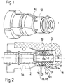
- the insert part 3a thus forms with the seal 11 and the Pipe 2 an assembly, which as such in the housing G for the purpose of sealing is inserted.
- the rubber-elastic seal 11 has on its outer diameter an outwardly facing annular lip 15, which is under pretension the inner diameter of a bore of the housing G is under prestress, while at least one radially inward annular sealing lip 14 on the inside diameter the seal 11 under tension with the outer diameter of the tube 2 lies. The seal 11 is thus pressed into an annular gap with deformation, with an elastic deformation in favor of sealing this Annular gap results.
- the seal 11 detects one in the direction pointing in the direction of the insert part 3a radially outwardly facing annular formation 12, which is connected by a web 19 is connected to the seal 11.
- the radially outward-pointing ring engages behind Forming 12 a collar 4a, which is after assembly of the seal 11 on the insertion part 3a in an annular groove 9 formed over the web-shaped connection 19.
- This annular groove 9 is formed by a mounting ring 10, which is on the end face of the insertion part 3a is fastened and forms an annular first flat surface 5a on the collar 4a, which forms this annular groove 9 with an annular second flat surface 6a, the mounting ring 10 with an outer radial connection 7a the outer boundary this annular groove 9 represents.
- the mounting ring 10 is with the insertion part 3a indissolubly connected, so that he no longer differs from that even with the application of force Insert part 3a can be pulled off.
- the seal can 11 with its radially outwardly facing annular formation 12 in the Ring groove 9 are added from the inside. Leave the two parts 11 and 3a so assembled however, separate from each other by an axially separating force, since the molding 12 pull out of the annular groove 9 again after a certain tensile force leaves, because the elasticity of the rubber-elastic material is not sufficient attachment offers.
- an insertion part 3b is proposed, which with a Bund 4b and a radially outer connection 7b is made in one piece, the Ring groove 9 on this one-piece insert part 3b during manufacture
- Execution of the insertion part 3b leaves an undamaged annular first Flat surface 5d, whereby the holding force between the seal 11 and the insertion part 3d is guaranteed, which has already been described with reference to FIGS. 1 and 2 has been.
- the annular groove 9 is thus from the annular first plane surface 5d and a second annular second likewise running all around intact Flat surface 6b formed.
- the locking of the joint between the seal 11 and the insertion part 3b is also made through the tube 2, which in the two pre-assembled parts 3b and 11 is inserted.
- radially outer connection 7b just described has two defects 8a, which arise when you form the slide valves identically 5 a defect 8b in a radially outer connection 7c of a collar 4c proposed by the one-sided design of a slide valve for connection of the federal government 4c and for the production of the annular groove 9 which runs at least on one side arises.
- the defect 8b in the connection 7c is larger than one of the defects 8a in the connection 7d according to Figures 3 and 4, but has the formation of a ring extending first plane surface 5c and its integrity as well as on the training an annular second plane surface 6c and its integrity none Influence, so that the perfect fit of the seal 11 on the insertion part 3c also by the sufficiently large design of a radially outer connection 7c for the federal government 4c is guaranteed.
- the insertion part 3c has an annular end against the seal 11 on its end face Sealing surface 13, which has a radially inward-pointing radius Ri, the when mounting with a radially outward radius Ra on the ring-shaped Forming 12 on the seal 11 cooperates in such a way that the seal 11 can easily be added to the insertion part 3c by simply sealing the seal 11 radially presses against the insertion part 3c.
- the projection 12 is thereby radially inward rejected and snaps to form a hook-like, resilient even on train Insert connection in the ring groove 9. As already described, this joint connection by inserting the tube 2 into the insert part 3 and the seal 11 locked.
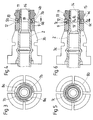
- an insert part 3d / 3e is shown which also with the seal 11 how the insert parts 3c and 3b can be joined.
- the two-part design of the insert part 3d becomes accomplished by a parting plane along a central axis M of the insert part 3d, whereby two identical halves 3d1 and 3d2 are joined to form the unit 3d.
- the insertion part 3e is also in two parts in the Way executed that a first half 3e1 with a second half 3e2 over at least a film hinge 17 is connected, the annular groove shown in FIG. 10 9 easily by a likewise two-part tool in the fully opened state can be produced.
- the closure of the two halves 3e1 and 3e2 becomes analogous to the two parts Execution of the insert part 3d accomplished via holding buttons.
- the ring groove 9 which is now easy to manufacture, is designed to be intact annular first and second plane surfaces 5d, 5e and 6d, 6e can be produced.
- the collar 4d, 4c has a slope S, which rejects the formation 12 even more easily than the assembly of the seal 11 5 with the radii Ra, Ri. Installation is facilitated by an internal one Slant Si on the seal 11, the retraction of the formation 12 when Pushing the collar 4d, 4c causes. It also introduces the tube 2 in the insertion part 3d, 3c and in the seal 11 with the slope Si made safer.
Landscapes
- Engineering & Computer Science (AREA)
- General Engineering & Computer Science (AREA)
- Mechanical Engineering (AREA)
- Quick-Acting Or Multi-Walled Pipe Joints (AREA)
- Gasket Seals (AREA)
- Joints With Sleeves (AREA)
Applications Claiming Priority (2)
| Application Number | Priority Date | Filing Date | Title |
|---|---|---|---|
| DE19848213 | 1998-10-20 | ||
| DE19848213A DE19848213C2 (de) | 1998-10-20 | 1998-10-20 | Dichtung für eine Steckverbindung |
Publications (3)
| Publication Number | Publication Date |
|---|---|
| EP0995938A2 true EP0995938A2 (fr) | 2000-04-26 |
| EP0995938A3 EP0995938A3 (fr) | 2002-03-06 |
| EP0995938B1 EP0995938B1 (fr) | 2005-03-23 |
Family
ID=7884997
Family Applications (1)
| Application Number | Title | Priority Date | Filing Date |
|---|---|---|---|
| EP99116013A Expired - Lifetime EP0995938B1 (fr) | 1998-10-20 | 1999-08-14 | Joint d'étancheite pour raccord enfichable |
Country Status (4)
| Country | Link |
|---|---|
| US (1) | US6454314B1 (fr) |
| EP (1) | EP0995938B1 (fr) |
| BR (1) | BR9902717A (fr) |
| DE (2) | DE19848213C2 (fr) |
Cited By (3)
| Publication number | Priority date | Publication date | Assignee | Title |
|---|---|---|---|---|
| US10527212B2 (en) | 2016-12-27 | 2020-01-07 | Hyundai Motor Company | Hydraulic tube connector for vehicle |
| US10533686B2 (en) | 2017-06-12 | 2020-01-14 | Hyundai Motor Company | Hydraulic tube connector for vehicle |
| US10563801B2 (en) | 2016-11-28 | 2020-02-18 | Hyundai Motor Company | Hydraulic tube connector for vehicle |
Families Citing this family (50)
| Publication number | Priority date | Publication date | Assignee | Title |
|---|---|---|---|---|
| DE10026748C2 (de) * | 2000-05-30 | 2003-07-24 | Woco Franz Josef Wolf & Co Gmbh | Dichtung sowie diese verwendende Dichtungsanordnung |
| CN1653272B (zh) * | 2002-05-14 | 2013-06-05 | 卢克摩擦片和离合器两合公司 | 液压系统 |
| JP4096832B2 (ja) * | 2003-07-22 | 2008-06-04 | 株式会社デンソー | 冷凍サイクル用配管継手 |
| JP2005106133A (ja) * | 2003-09-29 | 2005-04-21 | Aisin Seiki Co Ltd | 配管用継手 |
| FI20031736A (fi) * | 2003-11-27 | 2005-05-28 | Uponor Innovation Ab | Putkiyhde |
| CA2457978A1 (fr) * | 2004-02-19 | 2005-08-19 | Dana Canada Corporation | Raccord pour elements male et femelle |
| BRPI0516447B1 (pt) * | 2004-10-07 | 2018-07-03 | Schaeffler Technologies AG & Co. KG | Disposição de conexão para a conexão de um tubo a um sistema |
| US7448653B2 (en) | 2005-06-10 | 2008-11-11 | Value Plastics, Inc. | Female connector for releasable coupling with a male connector defining a fluid conduit |
| DE102005050490A1 (de) * | 2005-10-21 | 2007-04-26 | Henn Gmbh & Co. Kg | Steckverbindung an Rohren und Schläuchen mit einem Rohrrastring |
| US7806139B2 (en) | 2006-01-20 | 2010-10-05 | Value Plastics, Inc. | Fluid conduit coupling assembly having male and female couplers with integral valves |
| DE102006015555B3 (de) * | 2006-03-31 | 2007-01-25 | Fte Automotive Gmbh | Dichtungsanordnung für eine hydraulische Steckverbindung |
| EP2027407B1 (fr) * | 2006-06-14 | 2020-06-10 | Carl Freudenberg KG | Composants de joint de tube |
| US7832773B2 (en) * | 2006-09-18 | 2010-11-16 | Krohn Kenneth P | Adjustable connector and method for its use |
| US8109539B2 (en) * | 2007-07-17 | 2012-02-07 | Krohn Kenneth P | Variable joining device and method for its use |
| USD654573S1 (en) | 2007-11-19 | 2012-02-21 | Value Plastics, Inc. | Female quick connect fitting |
| EP2243149B1 (fr) * | 2008-02-15 | 2011-11-09 | Bekaert Advanced Coatings NV. | Couplage à vide à plusieurs rainures |
| US20090208271A1 (en) * | 2008-02-19 | 2009-08-20 | Krohn Kenneth P | Modular coupling system |
| US20090218808A1 (en) * | 2008-03-01 | 2009-09-03 | Krohn Kenneth P | Improved duct coupling system |
| US20090230678A1 (en) * | 2008-03-14 | 2009-09-17 | Krohn Kenneth P | Compression fitting adjustment system |
| US8235426B2 (en) | 2008-07-03 | 2012-08-07 | Nordson Corporation | Latch assembly for joining two conduits |
| US20100019484A1 (en) * | 2008-07-23 | 2010-01-28 | Krohn Kenneth P | Compression fitting adjustment system |
| WO2010045051A1 (fr) | 2008-10-13 | 2010-04-22 | Ethicon, Inc. | Séparateur de canal d'endoscope |
| CA2740427C (fr) * | 2008-10-13 | 2017-03-28 | Ethicon, Inc. | Raccord fluidique pour systeme de retraitement des endoscopes |
| CN102186399B (zh) | 2008-10-13 | 2014-08-20 | 伊西康公司 | 快速断开流体连接器 |
| US20100133810A1 (en) * | 2008-11-29 | 2010-06-03 | Krohn Kenneth P | Device for connecting to ducts of various sizes and shapes |
| JP5614793B2 (ja) * | 2008-12-12 | 2014-10-29 | 矢崎総業株式会社 | パッキンの誤組付け防止構造 |
| US20100283237A1 (en) * | 2009-01-24 | 2010-11-11 | Krohn Kenneth P | Device for connecting to ducts of various sizes and shapes |
| USD655393S1 (en) | 2009-06-23 | 2012-03-06 | Value Plastics, Inc. | Multi-port valve |
| USD783815S1 (en) | 2009-12-09 | 2017-04-11 | General Electric Company | Male dual lumen bayonet connector |
| USD649240S1 (en) | 2009-12-09 | 2011-11-22 | Value Plastics, Inc. | Male dual lumen bayonet connector |
| USD650478S1 (en) | 2009-12-23 | 2011-12-13 | Value Plastics, Inc. | Female dual lumen connector |
| US10711930B2 (en) | 2009-12-09 | 2020-07-14 | Nordson Corporation | Releasable connection assembly |
| US9388929B2 (en) | 2009-12-09 | 2016-07-12 | Nordson Corporation | Male bayonet connector |
| CN102753876B (zh) | 2009-12-23 | 2015-07-22 | 诺信公司 | 具有一体式模制悬臂弹簧的按钮闩 |
| KR101715636B1 (ko) | 2009-12-23 | 2017-03-13 | 노드슨 코포레이션 | 프로파일 리드-인을 갖는 유체 커넥터 래치 |
| USD652510S1 (en) | 2011-02-11 | 2012-01-17 | Value Plastics, Inc. | Connector for fluid tubing |
| USD652511S1 (en) | 2011-02-11 | 2012-01-17 | Value Plastics, Inc. | Female body of connector for fluid tubing |
| USD663022S1 (en) | 2011-02-11 | 2012-07-03 | Nordson Corporation | Male body of connector for fluid tubing |
| USD699840S1 (en) | 2011-07-29 | 2014-02-18 | Nordson Corporation | Male body of connector for fluid tubing |
| USD699841S1 (en) | 2011-07-29 | 2014-02-18 | Nordson Corporation | Female body of connector for fluid tubing |
| USD698440S1 (en) | 2011-07-29 | 2014-01-28 | Nordson Corporation | Connector for fluid tubing |
| USD709612S1 (en) | 2011-12-23 | 2014-07-22 | Nordson Corporation | Female dual lumen connector |
| DE102013017499B4 (de) * | 2013-10-17 | 2018-03-29 | Kaco Gmbh + Co. Kg | Brennraumabdichtung für Verbrennungsmotoren von Fahrzeugen, vorzugsweise von Kraftfahrzeugen |
| KR101519275B1 (ko) * | 2013-12-20 | 2015-05-11 | 현대자동차주식회사 | 차량용 유압튜브 |
| DE102014214186A1 (de) * | 2014-07-22 | 2016-01-28 | Schaeffler Technologies AG & Co. KG | Verbindungsvorrichtung |
| US20200316582A1 (en) * | 2016-05-30 | 2020-10-08 | Nok Corporation | Liquid injection attachment |
| USD838366S1 (en) | 2016-10-31 | 2019-01-15 | Nordson Corporation | Blood pressure connector |
| US10947938B2 (en) | 2017-06-21 | 2021-03-16 | Steere Enterprises, Inc. | Air duct assembly with a secured seal |
| US10788150B2 (en) | 2018-03-22 | 2020-09-29 | Freudenberg-Nok General Partnership | Tube seal |
| US11867333B2 (en) | 2018-06-06 | 2024-01-09 | Stäubli Hamburg GmbH | Fluid coupling |
Citations (1)
| Publication number | Priority date | Publication date | Assignee | Title |
|---|---|---|---|---|
| DE19714801C1 (de) | 1996-07-13 | 1998-01-02 | Ebern Fahrzeugtech Gmbh | Elastisches Dichtelement für eine hydraulische Steckverbindung |
Family Cites Families (17)
| Publication number | Priority date | Publication date | Assignee | Title |
|---|---|---|---|---|
| US2560263A (en) * | 1946-05-09 | 1951-07-10 | Wright Aeronautical Corp | Fluid line connection |
| US3430990A (en) * | 1966-11-02 | 1969-03-04 | Goddard Ind Inc | Coupling |
| GB1158358A (en) * | 1968-06-28 | 1969-07-16 | Hepworth Iron Co Ltd | Improvements in or relating to Pipe Couplings. |
| NL7711290A (nl) * | 1977-10-14 | 1979-04-18 | Teewen Bv | Buiskoppeling. |
| DE7830404U1 (de) | 1978-10-12 | 1979-06-13 | Matijas, Jovan, 7700 Singen | Vorrichtung fuer ein fahrzeug zur feststellung der intensitaet und gleichmaessigkeit seiner verzoegerung |
| US4422673A (en) * | 1980-06-04 | 1983-12-27 | Lucas Industries Limited | Pipe couplings |
| DE3531926A1 (de) | 1985-09-07 | 1987-03-19 | Kugelfischer G Schaefer & Co | Loesbare steckverbindung |
| JPS62113993A (ja) * | 1985-11-13 | 1987-05-25 | 株式会社 トヨツクス | 螺旋補強ホ−ス用継手 |
| US4915421A (en) * | 1988-03-30 | 1990-04-10 | Itt Corporation | Quick connector assembly |
| US5462313A (en) * | 1993-10-26 | 1995-10-31 | Form Rite Corporation | Quick connect coupling |
| US5573279A (en) * | 1994-01-03 | 1996-11-12 | Form Rite Corporation | Quick connect coupling |
| US5542717A (en) * | 1994-01-03 | 1996-08-06 | Form Rite, Corporation | Quick connect coupling |
| US5779279A (en) * | 1994-05-24 | 1998-07-14 | Proprietary Technology, Inc. | Connection verification and secondary latch device |
| DE19510192A1 (de) * | 1995-03-21 | 1996-09-26 | Voss Armaturen | Anschlußvorrichtung zum Anschluß von Rohrleitungen an ein Aggregateteil |
| DE19516096C1 (de) * | 1995-05-03 | 1996-11-14 | Trinova Aeroquip Gmbh | Schnellkupplung, insbesondere für Kältemittelleitungen |
| US5707085A (en) * | 1996-09-12 | 1998-01-13 | General Motors Corporation | Fluid coupling |
| US6273478B1 (en) * | 1999-03-30 | 2001-08-14 | The Regents Of The University Of California | Microfluidic interconnects |
-
1998
- 1998-10-20 DE DE19848213A patent/DE19848213C2/de not_active Expired - Fee Related
-
1999
- 1999-07-12 BR BR9902717-8A patent/BR9902717A/pt not_active IP Right Cessation
- 1999-08-14 EP EP99116013A patent/EP0995938B1/fr not_active Expired - Lifetime
- 1999-08-14 DE DE59911792T patent/DE59911792D1/de not_active Expired - Lifetime
- 1999-10-20 US US09/421,642 patent/US6454314B1/en not_active Expired - Fee Related
Patent Citations (1)
| Publication number | Priority date | Publication date | Assignee | Title |
|---|---|---|---|---|
| DE19714801C1 (de) | 1996-07-13 | 1998-01-02 | Ebern Fahrzeugtech Gmbh | Elastisches Dichtelement für eine hydraulische Steckverbindung |
Cited By (3)
| Publication number | Priority date | Publication date | Assignee | Title |
|---|---|---|---|---|
| US10563801B2 (en) | 2016-11-28 | 2020-02-18 | Hyundai Motor Company | Hydraulic tube connector for vehicle |
| US10527212B2 (en) | 2016-12-27 | 2020-01-07 | Hyundai Motor Company | Hydraulic tube connector for vehicle |
| US10533686B2 (en) | 2017-06-12 | 2020-01-14 | Hyundai Motor Company | Hydraulic tube connector for vehicle |
Also Published As
| Publication number | Publication date |
|---|---|
| DE19848213C2 (de) | 2002-08-08 |
| EP0995938B1 (fr) | 2005-03-23 |
| EP0995938A3 (fr) | 2002-03-06 |
| DE19848213A1 (de) | 2000-04-27 |
| US6454314B1 (en) | 2002-09-24 |
| BR9902717A (pt) | 2000-05-30 |
| DE59911792D1 (de) | 2005-04-28 |
Similar Documents
| Publication | Publication Date | Title |
|---|---|---|
| EP0995938A2 (fr) | Joint d'étancheite pour raccord enfichable | |
| DE3310385C3 (de) | Rohrkupplung | |
| DE69710321T2 (de) | Ventil, kupplung mit einem solchen ventil, sowie verfahren zum zusammenbau der kupplung | |
| DE69520669T2 (de) | Tiefziehbare schnellkupplung | |
| EP2054648B1 (fr) | Manchon d'étanchéité ou soufflet | |
| DE69107900T2 (de) | Kunststoff-Schnellverbindungskupplung. | |
| DE3606408C2 (de) | Lösbarer Steckverbinder-Rohranschluß | |
| DE4101757A1 (de) | Verbinder zum verbinden eines duennen rohres | |
| WO2007045281A1 (fr) | Connexion enfichable au niveau de tubes et de tuyaux, comprenant un anneau d'encliquetage de tubes | |
| EP1567800B1 (fr) | Raccord de conduite emboitable et blocable | |
| DE60205641T2 (de) | Zur verbindung zweier röhrenförmiger elemente verwendete kupplung und montageverfahren dafür | |
| EP1636521B1 (fr) | Dispositif de raccordement pour un tuyau ou un element similaire | |
| EP0545037A1 (fr) | Dispositif d'accouplement de deux conduites, en particulier pour des conduites de carburant | |
| DE102004016599B3 (de) | Steckverbindung mit Winkelarretierung | |
| DE19601667C2 (de) | Steckverbindung für den Anschluß von Rohr- und Schlauchleitungen | |
| EP0618393B1 (fr) | Dispositif de raccordement pour tuyaux flexibles et/ou tuyaux rigides | |
| EP0178626B1 (fr) | Manchon d'accouplement pour raccorder deux extrémités de tuyaux | |
| EP1126206B1 (fr) | Raccord de compression pour tuyaux | |
| DE4310795C1 (de) | Steckkupplung | |
| DE3010459A1 (de) | Rohr- oder schlauchleitungskupplung | |
| DE4308526B4 (de) | Steckkupplung für Rohr- und/oder Schlauchleitungen | |
| EP1361973B1 (fr) | Maitre-cylindre | |
| DE19932602C2 (de) | Rohrkupplung | |
| AT388426B (de) | Kupplungsanordnung fuer wenigstens eine rohrleitung sowie dichtunsstopfen hiefuer | |
| WO2021209212A1 (fr) | Unité de raccordement pour raccorder des conduites de fluide |
Legal Events
| Date | Code | Title | Description |
|---|---|---|---|
| PUAI | Public reference made under article 153(3) epc to a published international application that has entered the european phase |
Free format text: ORIGINAL CODE: 0009012 |
|
| AK | Designated contracting states |
Kind code of ref document: A2 Designated state(s): AT BE CH CY DE DK ES FI FR GB GR IE IT LI LU MC NL PT SE Kind code of ref document: A2 Designated state(s): DE ES FR GB |
|
| AX | Request for extension of the european patent |
Free format text: AL;LT;LV;MK;RO;SI |
|
| PUAL | Search report despatched |
Free format text: ORIGINAL CODE: 0009013 |
|
| RAP1 | Party data changed (applicant data changed or rights of an application transferred) |
Owner name: ZF SACHS AG |
|
| RIC1 | Information provided on ipc code assigned before grant |
Free format text: 7F 16L 37/04 A, 7F 16L 37/02 B |
|
| AK | Designated contracting states |
Kind code of ref document: A3 Designated state(s): AT BE CH CY DE DK ES FI FR GB GR IE IT LI LU MC NL PT SE |
|
| AX | Request for extension of the european patent |
Free format text: AL;LT;LV;MK;RO;SI |
|
| 17P | Request for examination filed |
Effective date: 20020205 |
|
| AKX | Designation fees paid |
Free format text: DE ES FR GB |
|
| 17Q | First examination report despatched |
Effective date: 20030707 |
|
| GRAP | Despatch of communication of intention to grant a patent |
Free format text: ORIGINAL CODE: EPIDOSNIGR1 |
|
| GRAS | Grant fee paid |
Free format text: ORIGINAL CODE: EPIDOSNIGR3 |
|
| GRAA | (expected) grant |
Free format text: ORIGINAL CODE: 0009210 |
|
| AK | Designated contracting states |
Kind code of ref document: B1 Designated state(s): DE ES FR GB |
|
| PG25 | Lapsed in a contracting state [announced via postgrant information from national office to epo] |
Ref country code: GB Free format text: LAPSE BECAUSE OF FAILURE TO SUBMIT A TRANSLATION OF THE DESCRIPTION OR TO PAY THE FEE WITHIN THE PRESCRIBED TIME-LIMIT Effective date: 20050323 |
|
| REG | Reference to a national code |
Ref country code: GB Ref legal event code: FG4D Free format text: NOT ENGLISH |
|
| REG | Reference to a national code |
Ref country code: IE Ref legal event code: FG4D Free format text: GERMAN |
|
| REF | Corresponds to: |
Ref document number: 59911792 Country of ref document: DE Date of ref document: 20050428 Kind code of ref document: P |
|
| PG25 | Lapsed in a contracting state [announced via postgrant information from national office to epo] |
Ref country code: ES Free format text: LAPSE BECAUSE OF FAILURE TO SUBMIT A TRANSLATION OF THE DESCRIPTION OR TO PAY THE FEE WITHIN THE PRESCRIBED TIME-LIMIT Effective date: 20050704 |
|
| GBV | Gb: ep patent (uk) treated as always having been void in accordance with gb section 77(7)/1977 [no translation filed] |
Effective date: 20050323 |
|
| PLBE | No opposition filed within time limit |
Free format text: ORIGINAL CODE: 0009261 |
|
| STAA | Information on the status of an ep patent application or granted ep patent |
Free format text: STATUS: NO OPPOSITION FILED WITHIN TIME LIMIT |
|
| ET | Fr: translation filed | ||
| 26N | No opposition filed |
Effective date: 20051227 |
|
| PGFP | Annual fee paid to national office [announced via postgrant information from national office to epo] |
Ref country code: FR Payment date: 20100824 Year of fee payment: 12 |
|
| REG | Reference to a national code |
Ref country code: FR Ref legal event code: ST Effective date: 20120430 |
|
| PG25 | Lapsed in a contracting state [announced via postgrant information from national office to epo] |
Ref country code: FR Free format text: LAPSE BECAUSE OF NON-PAYMENT OF DUE FEES Effective date: 20110831 |
|
| REG | Reference to a national code |
Ref country code: DE Ref legal event code: R081 Ref document number: 59911792 Country of ref document: DE Owner name: ZF FRIEDRICHSHAFEN AG, DE Free format text: FORMER OWNER: ZF SACHS AG, 97424 SCHWEINFURT, DE Effective date: 20121030 |
|
| PGFP | Annual fee paid to national office [announced via postgrant information from national office to epo] |
Ref country code: DE Payment date: 20120808 Year of fee payment: 14 |
|
| PG25 | Lapsed in a contracting state [announced via postgrant information from national office to epo] |
Ref country code: DE Free format text: LAPSE BECAUSE OF NON-PAYMENT OF DUE FEES Effective date: 20140301 |
|
| REG | Reference to a national code |
Ref country code: DE Ref legal event code: R119 Ref document number: 59911792 Country of ref document: DE Effective date: 20140301 |