EP0995924A2 - Schwingungsisolator mit magnetischen Federn - Google Patents
Schwingungsisolator mit magnetischen Federn Download PDFInfo
- Publication number
- EP0995924A2 EP0995924A2 EP99120743A EP99120743A EP0995924A2 EP 0995924 A2 EP0995924 A2 EP 0995924A2 EP 99120743 A EP99120743 A EP 99120743A EP 99120743 A EP99120743 A EP 99120743A EP 0995924 A2 EP0995924 A2 EP 0995924A2
- Authority
- EP
- European Patent Office
- Prior art keywords
- vibration isolator
- lower frame
- vibration
- acceleration
- magnetic
- Prior art date
- Legal status (The legal status is an assumption and is not a legal conclusion. Google has not performed a legal analysis and makes no representation as to the accuracy of the status listed.)
- Granted
Links
- 230000001133 acceleration Effects 0.000 claims abstract description 39
- 230000007246 mechanism Effects 0.000 claims abstract description 7
- 230000033001 locomotion Effects 0.000 claims description 11
- 238000013016 damping Methods 0.000 description 11
- 230000005484 gravity Effects 0.000 description 11
- 239000004020 conductor Substances 0.000 description 10
- 230000002238 attenuated effect Effects 0.000 description 8
- 239000006096 absorbing agent Substances 0.000 description 7
- 230000035939 shock Effects 0.000 description 7
- 210000001624 hip Anatomy 0.000 description 6
- 229910052751 metal Inorganic materials 0.000 description 6
- 239000002184 metal Substances 0.000 description 6
- 239000000725 suspension Substances 0.000 description 5
- 238000010276 construction Methods 0.000 description 4
- 238000006243 chemical reaction Methods 0.000 description 3
- 238000006073 displacement reaction Methods 0.000 description 3
- 230000005674 electromagnetic induction Effects 0.000 description 3
- 230000004907 flux Effects 0.000 description 3
- 238000005259 measurement Methods 0.000 description 3
- 230000000452 restraining effect Effects 0.000 description 3
- 238000012360 testing method Methods 0.000 description 3
- 229910052782 aluminium Inorganic materials 0.000 description 2
- XAGFODPZIPBFFR-UHFFFAOYSA-N aluminium Chemical compound [Al] XAGFODPZIPBFFR-UHFFFAOYSA-N 0.000 description 2
- 238000011156 evaluation Methods 0.000 description 2
- 238000012986 modification Methods 0.000 description 2
- 230000004048 modification Effects 0.000 description 2
- 230000009467 reduction Effects 0.000 description 2
- 230000004044 response Effects 0.000 description 2
- 230000001953 sensory effect Effects 0.000 description 2
- 230000003595 spectral effect Effects 0.000 description 2
- 230000003068 static effect Effects 0.000 description 2
- 210000001835 viscera Anatomy 0.000 description 2
- 230000003213 activating effect Effects 0.000 description 1
- 239000008280 blood Substances 0.000 description 1
- 210000004369 blood Anatomy 0.000 description 1
- 230000036772 blood pressure Effects 0.000 description 1
- 239000012141 concentrate Substances 0.000 description 1
- 238000012937 correction Methods 0.000 description 1
- 230000000994 depressogenic effect Effects 0.000 description 1
- 238000010586 diagram Methods 0.000 description 1
- 230000000694 effects Effects 0.000 description 1
- 238000002955 isolation Methods 0.000 description 1
- 239000011435 rock Substances 0.000 description 1
- 238000005096 rolling process Methods 0.000 description 1
- 238000013519 translation Methods 0.000 description 1
Images






Classifications
-
- F—MECHANICAL ENGINEERING; LIGHTING; HEATING; WEAPONS; BLASTING
- F16—ENGINEERING ELEMENTS AND UNITS; GENERAL MEASURES FOR PRODUCING AND MAINTAINING EFFECTIVE FUNCTIONING OF MACHINES OR INSTALLATIONS; THERMAL INSULATION IN GENERAL
- F16F—SPRINGS; SHOCK-ABSORBERS; MEANS FOR DAMPING VIBRATION
- F16F7/00—Vibration-dampers; Shock-absorbers
-
- A—HUMAN NECESSITIES
- A61—MEDICAL OR VETERINARY SCIENCE; HYGIENE
- A61G—TRANSPORT, PERSONAL CONVEYANCES, OR ACCOMMODATION SPECIALLY ADAPTED FOR PATIENTS OR DISABLED PERSONS; OPERATING TABLES OR CHAIRS; CHAIRS FOR DENTISTRY; FUNERAL DEVICES
- A61G3/00—Ambulance aspects of vehicles; Vehicles with special provisions for transporting patients or disabled persons, or their personal conveyances, e.g. for facilitating access of, or for loading, wheelchairs
- A61G3/006—Means for reducing the influence of acceleration on patients, e.g. suspension systems of platforms
-
- A—HUMAN NECESSITIES
- A61—MEDICAL OR VETERINARY SCIENCE; HYGIENE
- A61G—TRANSPORT, PERSONAL CONVEYANCES, OR ACCOMMODATION SPECIALLY ADAPTED FOR PATIENTS OR DISABLED PERSONS; OPERATING TABLES OR CHAIRS; CHAIRS FOR DENTISTRY; FUNERAL DEVICES
- A61G1/00—Stretchers
- A61G1/06—Supports for stretchers, e.g. to be placed in or on vehicles
-
- A—HUMAN NECESSITIES
- A61—MEDICAL OR VETERINARY SCIENCE; HYGIENE
- A61G—TRANSPORT, PERSONAL CONVEYANCES, OR ACCOMMODATION SPECIALLY ADAPTED FOR PATIENTS OR DISABLED PERSONS; OPERATING TABLES OR CHAIRS; CHAIRS FOR DENTISTRY; FUNERAL DEVICES
- A61G3/00—Ambulance aspects of vehicles; Vehicles with special provisions for transporting patients or disabled persons, or their personal conveyances, e.g. for facilitating access of, or for loading, wheelchairs
-
- F—MECHANICAL ENGINEERING; LIGHTING; HEATING; WEAPONS; BLASTING
- F16—ENGINEERING ELEMENTS AND UNITS; GENERAL MEASURES FOR PRODUCING AND MAINTAINING EFFECTIVE FUNCTIONING OF MACHINES OR INSTALLATIONS; THERMAL INSULATION IN GENERAL
- F16F—SPRINGS; SHOCK-ABSORBERS; MEANS FOR DAMPING VIBRATION
- F16F6/00—Magnetic springs; Fluid magnetic springs, i.e. magnetic spring combined with a fluid
- F16F6/005—Magnetic springs; Fluid magnetic springs, i.e. magnetic spring combined with a fluid using permanent magnets only
Definitions
- the present invention relates to a vibration isolator for use in, for example, an ambulance for carrying sick or wounded people to make them more comfortable.
- Vibration isolators that perform an active control to improve the riding comfort have been proposed.
- the running of ambulances includes ordinary running, in which they run with the steam of cars, and special running when they are called in an emergency.
- the riding comfort differs between the ordinary running and the special running.
- the present invention has been developed to overcome the above-described disadvantages.
- the vibration isolator includes a lower frame movably mounted on a floor, an upper frame vertically movably mounted on the lower frame, a link mechanism coupled to the upper and lower frames, operable to move the upper frame relative to the lower frame, and a plurality of magnetic springs interposed between the upper and lower frames and each having a plurality of permanent magnets with like magnetic poles opposed to each other.
- a vertical vibration of the upper frame relative to the lower frame is restrained by the plurality of magnetic springs, and the front side of the vibration isolator is lifted upon receipt of a forward acceleration.
- an acceleration inputted in a direction longitudinally of the vibration isolator is restrained by virtue of a single-sided pendulum motion about an instantaneous center of rotation of the lower frame.
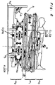
- the vibration isolator A includes two lower frames 2a, 2b secured to each other and mounted on a floor so as to be movable in the longitudinal direction thereof, an upper frame 4 vertically movably mounted on the lower frames 2a, 2b, and a top plate 6 longitudinally slidably mounted on the upper frame 4.
- the two lower frames 2a, 2b are sometimes referred to simply as a lower frame 2 hereinafter.
- Each of the lower frames 2a, 2b is provided with a conductor 8a, 8b such as, for example, aluminum secured to the lower surface thereof.
- the conductor 8a (8b) is mounted, via levers 12a (12b) disposed on respective sides thereof, on support plates 10a (10b) extending upwardly from the floor so as to be movable in the longitudinal direction of the vibration isolator A.
- Two permanent magnets 14a (or 14b), which are spaced a predetermined distance from each other, are securely mounted on the floor on respective sides of each conductor 8a (or 8b).
- the upper frame 4 is coupled to the lower frame 2 via X-shaped links 16a, 16b and pantographs 18a, 18b, both disposed on respective sides thereof.
- Each of the X-shaped links 16a, 16b includes two relatively long levers 20,22, each of which is pivotally connected at one end thereof to the upper frame 4 or the lower frame 2.
- the other end of the lever 20 is pivotally connected to one end of a relatively short lever 26, the other end of which is pivotally connected to an upper end of a support member 30 extending upwardly from the lower frame 2.
- the other end of the lever 22 is pivotally connected to one end of a relatively short lever 24, the other end of which is pivotally connected to a lower end of a support member 28 extending downwardly from the upper frame 4.
- the two relatively long levers 20, 22 are mutually pivotally connected at intermediate portions thereof.
- Each of the pantographs 18a, 18b includes four levers 32, 34, 36, 38.
- the two levers 32, 34, 36, 38 are pivotally connected to each other in the form of "L", while the other two levers 36, 38 are similarly pivotally connected to each other in a symmetric fashion relative to the two levers 32,34.
- the levers 32,36 are pivotally connected at upper ends thereof to the upper frame 4, while the levers 34, 38 are pivotally connected at lower ends thereof to the lower frame 2.
- a coil spring 40 is connected at one end thereof to a connecting portion between the two levers 32, 34 and the other end thereof to a connecting portion between the other two levers 36, 38, thereby generating a lifting force of the upper frame 4.
- Each of the lower frames 2a, 2b is provided with a permanent magnet 42, 44 secured to the upper surface thereof at a center in the widthwise direction thereof.
- the permanent magnets 42, 44 confront permanent magnets 46, 48 secured to the lower surface of the upper frame 4, respectively, with like magnetic poles opposed to each other.
- a repulsive force acting between the two permanent magnets 42,46 and that acting between the two permanent magnets 44, 48 act as lifting forces of the upper frame 4.
- the lower frame 2 is connected, via a shock absorber 52 and a coil spring 54, to a support member 50 secured to the floor on the left-hand side as viewed in Fig. 1 (this side is hereinafter referred to as the head side of a sick or wounded person, while the opposite side is hereinafter referred to as the leg side).
- the top plate 6 is mounted on the upper frame 4 via sliders 56a, 56b disposed on respective sides thereof so as to be slidable in the longitudinal direction of the vibration isolator A.
- the top plate 6 is provided with two projections 58a, 58b secured to the lower surface thereof, while the upper frame 4 is provided with a projection 60 secured to the upper surface thereof and interposed between the two projections 58a, 58b of the top plate 6.
- Coil springs 62a, 62b and rubber dampers are interposed between the projection 58a of the top plate 6 and the projection 60 of the upper frame 4 and between the projection 58b of the top plate 6 and the projection 60 of the upper frame 4, respectively, thereby maintaining the top plate 6 at a predetermined position relative to the upper frame 4.
- the permanent magnets 42, 44, 46, 48, the shock absorber 52, the coil spring 54 and the like are disposed at the central portion of the vibration isolator A in the widthwise direction thereof ,while the other component parts are disposed on respective sides of the vibration isolator A, but only one side is shown in Fig. 1.
- the vibration isolator A of the above-described construction operates as follows.
- the vibration isolator A includes means for restraining pitching vibration of a living body, which may be caused by sudden braking or when running over a projection, or an acceleration created in the longitudinal direction. More specifically, the vibration isolating mechanism makes use of, as such means, two motions: a pseudo-single-sided pendulum motion about an instantaneous center of rotation of the lower frames 2a, 2b relative to the floor as means for restraining the motion of the head in the upward direction only, and a translation motion of the masses (m 0 +m 1 ) occurring in the same direction as the travel of the vehicle. In conventional active control systems, an acceleration of about 0.5G that is created in the event of sudden braking is reduced by making use of the acceleration of gravity.
- a reaction against the acceleration caused by the sudden braking is utilized to move the center of the masses (m 0 +m 1 ) rearwards (toward the leg side), thereby activating the metal spring (k 3 ) and the magnetic spring (k 4 ) on the rear side.
- the angle ⁇ of inclination of the top plate 6 becomes large.
- a component, directed in the direction of advance of the vibration isolator A, of the acceleration caused by the sudden braking is reduced by a component of the acceleration of gravity in the direction of advance of the vibration isolator A.
- the remainder is attenuated by the metal springs (k 1 , k 2 ), the rubber dampers (C 1 , C 2 ), and the magnetic dampers (C 3 ).
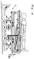
- Fig. 5 depicts an initial condition of the vibration isolator A on which a sick or wounded person together with a stretcher is placed.
- the upper frame 4 is maintained at an initial angle ⁇ 0 of inclination by the metal spring 54 and the shock absorber 52.
- an acceleration of, for example, about 0.5G is inputted to the vibration isolator A by sudden braking, it moves towards the head side against the biasing forces of the coil springs 62a with a point O shown in Fig. 2 as an instantaneous center of rotation.
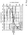
- Fig. 6 depicts the spring characteristics of the vibration isolating mechanism in response to the vertical vibration and the response amplitude at several frequencies when the vibration isolating mechanism has been oscillated by a sine wave having an acceleration amplitude of 0.3G.
- the relationship between the magnetic spring force and the displacement has been found from formulas (3) and (4), and the relationship between the metal spring force and the displacement has been found in view of the conversion of force by the link structure. The results fall within 5% variations with respect to actual measurements.
- the dynamic magnetic springs provide positive spring characteristics, for example, at point Q in Fig. 6, while the pantographs provide negative spring characteristics.
- the natural frequency of the metal spring (k 5 ) is set to a value higher than f.
- Both the shock absorber (C 4 ) and the magnetic dampers (C 3 ) provide damping characteristics.
- any optimum spring constant can be set by selecting the distance (z) between the magnets at the balanced position with the loaded mass, k m and F 0 being constants.
- f m 1 2 ⁇ ( mg - F 0 ) 2 m ⁇ k ( m )
- acceleration measurements and sensory evaluation were carried out using the car A having a floor of a large acceleration, the car B and a trial car C capable of reproducing the same acceleration as in the car A. All the cars A, B and C were caused to run on a paved road with the vibration isolator A according to the present invention mounted in the car C.
- Figs. 8 and 9 depict the PSD (Power Spectral Density) of the acceleration on the floor and the vibration transmissibility of the waist of the subject on the stretcher with respect to the longitudinal and vertical vibrations during actual running, respectively.
- the magnetic spring type vibration isolator A has a resonant frequency of about 2Hz with respect to the longitudinal vibration and a resonant frequency of about 3Hz with respect to the vertical vibration. These resonant frequencies deviate from the resonant frequencies of 0.4Hz and 2Hz of the floor, respectively.
- the graph of Fig. 8 reveals that the performance has been improved at low-frequency regions of about 0.3-1Hz and about 3Hz, and it is unlikely that resonance occurs on the head or legs having a resonant point in the range of 0.6-4Hz.
- f WB n ⁇ V L
- the car C has been improved as compared with the cars A and B in that the resonance of internal organs has been relieved at frequencies of 4-8Hz that correspond to a vehicle speed range of up to 80 km/h.
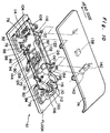
- Fig. 10 depicts a vibration isolator A1 according to a second embodiment of the present invention, which includes a lower frame 72 longitudinally movably mounted on the floor and an upper frame 74 vertically movably mounted on the lower frame 72.
- the lower frame 72 is mounted on the floor via a plurality of sliders 76 disposed at front and rear portions thereof so as to be slidable in the longitudinal direction of the vibration isolator A1.
- the lower frame 72 is coupled to the sliders 76 via a plurality of levers 78, 80 to allow a rocking motion thereof.
- Each of the levers 78 has a lower end pivotally mounted on the lower frame 72 and an upper end pivotally mounted on an upper end of a support plate 82 extending upwardly from the front slider 76.
- Each of the levers 80 has an upper end pivotally mounted on the lower frame 72 and a lower end pivotally mounted on an upper end of a support plate 84 extending upwardly from the rear slider 76.
- the upper frame 74 is coupled to the lower frame 72 via a plurality of y-shaped links and v-shaped links, both disposed on respective sides of the lower frame 72.
- Each of the y-shaped links is made up of a relatively long lever 86 and a relatively short lever 88.
- the long lever 86 has an upper end pivotally mounted on the upper frame 74 and a lower end pivotally mounted on a lower end of another lever 90, an upper end of which is pivotally mounted on a bracket 92 secured to the upper surface of the lower frame 72.
- the short lever 88 has an upper end pivotally mounted on an intermediate portion of the long lever 86 and a lower end pivotally mounted on the lower frame 72.
- the lower ends of the two long levers 86 and those of the two short levers 88 are connected to each other via rods 94, 96, respectively.
- a plurality of coil springs (not shown) are connected at opposite ends thereof to the rods 94, 96, respectively, to generate a lifting force of the upper frame 74.
- Each of the v-shaped links is made up of two levers 98, 100 pivotally connected to each other.
- An upper end of the upper lever 98 is pivotally connected to the upper frame 74, while a lower end of the lower lever 100 is pivotally connected to the lower frame 72.
- the connecting portion of the two levers 98, 100 is connected, via a rod 102, to the connecting portion of the long and short levers 86, 88 constituting the y-shaped link, thereby interlocking the y-shaped links and the associated v-shaped links with each other to vertically move the upper frame 74.
- the lower frame 72 has generally rectangular openings 104, 106 defined therein at front (head-side) and rear (leg-side) portions thereof, through which a projection 108 and permanent magnets 110, 112 secured to the floor extend, respectively.
- a plurality of coil springs 114, 116 are disposed in front of and behind the projection 108, while two permanent magnets 118, 120 are disposed in front of and behind the two permanent magnets 110, 112.
- the two permanent magnets 118, 120 are secured to the lower frame 72 and spaced from the permanent magnets 110, 112, respectively, with like (repulsive) magnetic poles opposed to each other, making it possible to attenuate a longitudinal movement of the lower frame 72.
- the lower frame 72 also has two generally rectangular openings 122, 124 defined therein in a side-by-side fashion at an intermediate portion thereof, through which permanent magnets 126, 128 secured to the floor extend, respectively.
- a conductor 130 made of, for example, aluminum and secured to the lower frame 72 is interposed between the two permanent magnets 126, 128 so that the longitudinal movement of the lower frame 72 may be attenuated by virtue of electromagnetic induction.
- a permanent magnet 132 and two permanent magnets 134, 136 are secured to the lower frame 72 at locations in front of and behind the conductor 130, respectively.
- the three permanent magnets 132, 134, 136 confront permanent magnets 138, 140, 142 secured to the upper frame 74 and are spaced a predetermined distance therefrom, respectively, with like magnetic poles opposed to each other.
- the two opposing permanent magnets constitute a magnetic spring to attenuate a vertical movement of the upper frame 74.
- the two permanent magnets 134, 136 are inclined with respect to the lower frame 72, while the two permanent magnets 140, 142 are similarly inclined with respect to the upper frame 74.
- Two shock absorbers 144 each having an upper end pivotally connected to the lower frame 72 and a lower end pivotally connected to the floor are disposed on respective sides of the lower frame 72 generally at the center thereof.
- the lower frame 72 Under the condition in which a stretcher together with a sick or wounded person is placed on the vibration isolator A1, the lower frame 72 is held at a predetermined position by the coil springs 114, 116, the permanent magnets 110, 112, 118, 120, the shock absorbers 144 and the like, as shown in Fig. 11A. At this moment, when an acceleration is inputted by, for example, sudden braking, the lower frame 72 is caused to rock to the head (front) side about the instantaneous center of rotation thereof against the biasing force of the coil springs 116 and the repulsive force of the permanent magnets 110, 118.
- the front lever 78 is pivotally connected at the upper end thereof to the slider 76 and at the lower end thereof to the lower frame 72, while the rear lever 80 is contrariwise pivotally connected at the upper end thereof to the lower frame 72 and at the lower end thereof to the slider 76, the head side of the lower frame 72 is lifted, whereas the leg side of the lower frame 72 is caused to drop.
- the vibration isolator A1 shown in Fig. 10 does not always require the rods 102 for connecting the y-shaped links and the v-shaped links.
- the y-shaped links and the v-shaped links operate independently. In that case, upon receipt of an acceleration caused by sudden braking, the angle of inclination of the upper frame 74 and the rearward component of the acceleration of gravity become larger, making it possible to effectively attenuate the forward component of the acceleration caused by the sudden braking.
- the magnetic springs made up of a plurality of permanent magnets with like magnetic poles opposed to each other act to restrain the vertical vibration, and the front side of the vibration isolator is lifted upon receipt of a forward acceleration caused by, for example, a rapid speed reduction. Accordingly, a component of the acceleration in the direction of advance of the vibration isolator is reduced by a component of the acceleration of gravity acting in the direction of advance of the vibration isolator, making it possible to improve the riding comfort of the vibration isolator.
- an acceleration inputted in the longitudinal direction of the vibration isolator is restrained by virtue of a single-sided pendulum motion about an instantaneous center of rotation of the lower frame.
Landscapes
- Public Health (AREA)
- Health & Medical Sciences (AREA)
- General Engineering & Computer Science (AREA)
- Engineering & Computer Science (AREA)
- Animal Behavior & Ethology (AREA)
- Life Sciences & Earth Sciences (AREA)
- General Health & Medical Sciences (AREA)
- Veterinary Medicine (AREA)
- Mechanical Engineering (AREA)
- Vibration Prevention Devices (AREA)
- Floor Finish (AREA)
- Arrangement Or Mounting Of Propulsion Units For Vehicles (AREA)
- Springs (AREA)
Applications Claiming Priority (2)
| Application Number | Priority Date | Filing Date | Title |
|---|---|---|---|
| JP10299510A JP3115864B2 (ja) | 1998-10-21 | 1998-10-21 | 救急車用除振架台 |
| JP29951098 | 1998-10-21 |
Publications (3)
| Publication Number | Publication Date |
|---|---|
| EP0995924A2 true EP0995924A2 (de) | 2000-04-26 |
| EP0995924A3 EP0995924A3 (de) | 2000-07-12 |
| EP0995924B1 EP0995924B1 (de) | 2003-10-29 |
Family
ID=17873529
Family Applications (1)
| Application Number | Title | Priority Date | Filing Date |
|---|---|---|---|
| EP99120743A Expired - Lifetime EP0995924B1 (de) | 1998-10-21 | 1999-10-20 | Schwingungsisolator mit magnetischen Federn |
Country Status (9)
| Country | Link |
|---|---|
| US (1) | US6241059B1 (de) |
| EP (1) | EP0995924B1 (de) |
| JP (1) | JP3115864B2 (de) |
| KR (1) | KR100342963B1 (de) |
| CN (1) | CN1132562C (de) |
| AT (1) | ATE253185T1 (de) |
| DE (1) | DE69912377T2 (de) |
| DK (1) | DK0995924T3 (de) |
| TW (1) | TW443927B (de) |
Cited By (3)
| Publication number | Priority date | Publication date | Assignee | Title |
|---|---|---|---|---|
| WO2007000133A1 (de) * | 2005-06-29 | 2007-01-04 | Zf Friedrichshafen Ag | Aufhängungseinrichtung mit scherenpantograph |
| CN108953448A (zh) * | 2018-08-10 | 2018-12-07 | 浙江理工大学 | 一种新型永磁式双稳态隔振器 |
| CN113136651A (zh) * | 2021-06-21 | 2021-07-20 | 南通喜丹奴纺织品有限公司 | 一种纺织加工用揉棉设备 |
Families Citing this family (36)
| Publication number | Priority date | Publication date | Assignee | Title |
|---|---|---|---|---|
| NL1007127C2 (nl) * | 1997-09-26 | 1999-03-29 | Univ Delft Tech | Draagsysteem. |
| JP2000337434A (ja) * | 1999-05-25 | 2000-12-05 | Delta Tooling Co Ltd | 振動機構 |
| JP2001059546A (ja) * | 1999-08-19 | 2001-03-06 | Delta Tooling Co Ltd | 除振装置及び磁気ダンパ機構 |
| US6805337B1 (en) * | 2000-03-02 | 2004-10-19 | Omnitek Research & Development, Inc. | Apparatus for isolation of payloads with low transmissibility |
| DE60144522D1 (de) * | 2000-08-24 | 2011-06-09 | Sirf Tech Inc | Vorrichtung zur reduzierung von autokorrelation und kreuzkorrelation bei schwachen cdma-signalen |
| US6493886B1 (en) * | 2000-10-04 | 2002-12-17 | Jeffrey D. Vanpage | Mattress suspension system for a vehicle |
| JP4931305B2 (ja) * | 2000-10-30 | 2012-05-16 | 株式会社デルタツーリング | マグネットユニット |
| US6708962B2 (en) * | 2001-03-21 | 2004-03-23 | Quality Research, Development & Consulting, Inc. | Smart isolation mounts with continuous structural elements featuring vibration energy management |
| US6419203B1 (en) * | 2001-07-20 | 2002-07-16 | Chi Hung Dang | Vibration isolator with parallelogram mechanism |
| US20040012168A1 (en) * | 2002-07-19 | 2004-01-22 | Martinrea International Inc. | Suspension system with magnetic resiliency |
| CA2436267C (en) * | 2003-07-30 | 2010-07-27 | Control And Metering Limited | Vibrating table assembly for bag filling apparatus |
| JP4603396B2 (ja) * | 2005-03-15 | 2010-12-22 | 株式会社デルタツーリング | シートサスペンション制御機構 |
| US8061692B1 (en) * | 2007-05-22 | 2011-11-22 | DIS Inc. | Floor isolation system |
| KR101554717B1 (ko) * | 2008-09-19 | 2015-09-21 | 울산대학교 산학협력단 | 낮은 고유 진동수를 가지는 진동 절연 시스템 |
| JP5818135B2 (ja) * | 2010-06-04 | 2015-11-18 | 株式会社デルタツーリング | 救急車用防振架台 |
| RU2516967C2 (ru) * | 2011-05-25 | 2014-05-20 | Владимир Александрович Смирнов | Виброизолятор квазинулевой жесткости |
| JP5930456B2 (ja) | 2011-11-08 | 2016-06-08 | 株式会社デルタツーリング | 救急車用防振架台 |
| CN103027796A (zh) * | 2012-07-18 | 2013-04-10 | 苏州江南航天机电工业有限公司 | 一种x型可展收的担架支架 |
| CN104896944B (zh) * | 2015-04-23 | 2017-01-11 | 浙江海洋学院 | 贝壳煅烧炉鼓风机支撑机构 |
| US10292877B2 (en) | 2015-09-09 | 2019-05-21 | Stryker Corporation | Patient transport apparatus for transporting a patient over disturbances in floor surfaces |
| CN105232241B (zh) * | 2015-10-20 | 2017-10-03 | 优弘智能医疗设备(重庆)有限公司 | 一种多功能心内科用担架系统 |
| CN105877931B (zh) * | 2016-05-24 | 2017-08-04 | 巢湖学院 | 一种四自由度并联减振担架平台 |
| CN105943259B (zh) * | 2016-05-24 | 2017-11-21 | 界首市华盛塑料机械有限公司 | 一种具备减振功能的担架 |
| CN110151405A (zh) * | 2018-03-12 | 2019-08-23 | 寿光新润科技中介服务有限公司 | 一种液压导向升降式减震气垫医疗转运床 |
| CN108836641B (zh) * | 2018-07-05 | 2019-12-24 | 张西亚 | 一种医用减震担架 |
| US11259972B2 (en) * | 2018-07-11 | 2022-03-01 | Richard C. Rapson, JR. | Techniques for mitigating dominant frequency imparted to object |
| US11579161B2 (en) * | 2019-04-16 | 2023-02-14 | Robotiques Haply Inc. | Orientation preserved damping for object tracking subjected to haptic stimulus |
| JP2020196328A (ja) * | 2019-05-31 | 2020-12-10 | デルタ工業株式会社 | リンク機構、乗物の上部収容棚構造及びシートサスペンション機構 |
| CN113027963A (zh) * | 2019-12-09 | 2021-06-25 | 标致雪铁龙汽车股份有限公司 | 一种尾门减震器及车辆 |
| JP7555098B2 (ja) * | 2020-07-13 | 2024-09-24 | 株式会社赤尾 | 救急車用防振架台 |
| CN111904723A (zh) * | 2020-08-28 | 2020-11-10 | 中国人民解放军联勤保障部队第九0四医院 | 一种船用担架外接减震装置 |
| RU2749467C1 (ru) * | 2020-10-21 | 2021-06-11 | Александр Алексеевич Трубецкой | Подвесная система транспортного средства трубецкого |
| CN113101068B (zh) * | 2021-04-13 | 2022-06-03 | 四川大学华西第二医院 | 一种新生儿转运装置 |
| CN114017461B (zh) * | 2021-11-12 | 2023-08-04 | 上海新纪元机器人有限公司 | 车载双层担架、车载双层担架的减振平台及控制方法 |
| CN116650230B (zh) * | 2023-06-01 | 2025-07-25 | 中国人民解放军空军军医大学 | 一种便携折叠式野外创伤急救担架 |
| CN117462341A (zh) * | 2023-11-08 | 2024-01-30 | 湘潭大学 | 一种双向惯容阻尼复合可调的救护车隔振担架及其控制方法 |
Family Cites Families (11)
| Publication number | Priority date | Publication date | Assignee | Title |
|---|---|---|---|---|
| IE35638B1 (en) | 1971-09-13 | 1976-04-14 | Inst For Ind Res & Standards | Construction of stabilised platform |
| JPS56882A (en) * | 1979-06-15 | 1981-01-07 | Sumitomo Heavy Ind Ltd | Lid-removing device of charging lid for coke oven |
| US4447041A (en) * | 1981-07-13 | 1984-05-08 | Osaka Taiyo Co., Ltd. | Device for lifting a table |
| JPS58124843A (ja) * | 1982-01-20 | 1983-07-25 | Mitsubishi Steel Mfg Co Ltd | 免震装置 |
| DE4115639A1 (de) * | 1991-05-14 | 1992-11-19 | Helge Katharina Lutz | Krankenwagen |
| JPH04371151A (ja) * | 1991-06-18 | 1992-12-24 | Toyota Motor Corp | 車両用ベッド |
| JPH0847510A (ja) * | 1994-08-05 | 1996-02-20 | Delta Kogyo Co Ltd | 防振ベッド |
| JP3524178B2 (ja) * | 1994-11-15 | 2004-05-10 | デルタ工業株式会社 | 磁気浮上式防振ベッド |
| CN1077966C (zh) * | 1996-04-08 | 2002-01-16 | 株式会社三角工具加工 | 具有阻尼特性的磁弹簧和具有所述磁弹簧的振动机构 |
| JP3924597B2 (ja) * | 1997-02-13 | 2007-06-06 | 株式会社デルタツーリング | 負の減衰特性を有する磁性バネ振動機構 |
| JP3252113B2 (ja) * | 1997-12-26 | 2002-01-28 | 花王株式会社 | 充填包装設備 |
-
1998
- 1998-10-21 JP JP10299510A patent/JP3115864B2/ja not_active Expired - Fee Related
-
1999
- 1999-10-20 AT AT99120743T patent/ATE253185T1/de not_active IP Right Cessation
- 1999-10-20 US US09/421,014 patent/US6241059B1/en not_active Expired - Lifetime
- 1999-10-20 DE DE69912377T patent/DE69912377T2/de not_active Expired - Fee Related
- 1999-10-20 DK DK99120743T patent/DK0995924T3/da active
- 1999-10-20 EP EP99120743A patent/EP0995924B1/de not_active Expired - Lifetime
- 1999-10-20 TW TW088118141A patent/TW443927B/zh not_active IP Right Cessation
- 1999-10-21 CN CN99123143A patent/CN1132562C/zh not_active Expired - Fee Related
- 1999-10-21 KR KR1019990045788A patent/KR100342963B1/ko not_active Expired - Fee Related
Non-Patent Citations (1)
| Title |
|---|
| None |
Cited By (6)
| Publication number | Priority date | Publication date | Assignee | Title |
|---|---|---|---|---|
| WO2007000133A1 (de) * | 2005-06-29 | 2007-01-04 | Zf Friedrichshafen Ag | Aufhängungseinrichtung mit scherenpantograph |
| US7950727B2 (en) | 2005-06-29 | 2011-05-31 | Zf Friedrichshafen Ag | Suspension means with scissor pantograph |
| CN108953448A (zh) * | 2018-08-10 | 2018-12-07 | 浙江理工大学 | 一种新型永磁式双稳态隔振器 |
| CN108953448B (zh) * | 2018-08-10 | 2024-03-26 | 浙江理工大学 | 一种永磁式双稳态隔振器 |
| CN113136651A (zh) * | 2021-06-21 | 2021-07-20 | 南通喜丹奴纺织品有限公司 | 一种纺织加工用揉棉设备 |
| CN113136651B (zh) * | 2021-06-21 | 2021-08-24 | 南通喜丹奴纺织品有限公司 | 一种纺织加工用揉棉设备 |
Also Published As
| Publication number | Publication date |
|---|---|
| JP3115864B2 (ja) | 2000-12-11 |
| CN1251292A (zh) | 2000-04-26 |
| KR20000029229A (ko) | 2000-05-25 |
| DE69912377T2 (de) | 2004-08-12 |
| DK0995924T3 (da) | 2004-02-23 |
| KR100342963B1 (ko) | 2002-07-05 |
| EP0995924A3 (de) | 2000-07-12 |
| CN1132562C (zh) | 2003-12-31 |
| US6241059B1 (en) | 2001-06-05 |
| JP2000126233A (ja) | 2000-05-09 |
| ATE253185T1 (de) | 2003-11-15 |
| TW443927B (en) | 2001-07-01 |
| DE69912377D1 (de) | 2003-12-04 |
| EP0995924B1 (de) | 2003-10-29 |
Similar Documents
| Publication | Publication Date | Title |
|---|---|---|
| EP0995924B1 (de) | Schwingungsisolator mit magnetischen Federn | |
| US6336627B1 (en) | Suspension unit having a magneto-spring | |
| JPH1130274A (ja) | 磁気バネを有する振動機構 | |
| US6585240B1 (en) | Vibration relief apparatus and magnetic damper mechanism therefor | |
| KR100365897B1 (ko) | 진동기구 | |
| CN109677305B (zh) | 一种半主动可控座椅悬架的振动和冲击混合控制方法 | |
| CN111376803A (zh) | 主动减震车辆座椅和车辆座椅主动减震的方法 | |
| JPH1086724A (ja) | 磁気浮上式サスペンションユニット | |
| JPH1086726A (ja) | 磁気浮上式サスペンションユニット | |
| KR100576897B1 (ko) | 시트의 진동완충장치 | |
| JP4187891B2 (ja) | 超電導アクチュエータ組み込みの空気バネ | |
| JP2004142709A (ja) | サスペンション装置 | |
| CN215689176U (zh) | 一种救护车用减震担架平台 | |
| JPH1086725A (ja) | 磁気浮上式サスペンションユニット | |
| JP2012205872A (ja) | 救急車用防振架台 | |
| Raine et al. | A two-degree-of-freedom ambulance stretcher suspension Part 1: system overview | |
| JPH10157504A (ja) | 磁気浮上式サスペンションユニット | |
| JPH1067267A (ja) | 磁気浮上式サスペンションユニット | |
| JPH04299004A (ja) | 磁気浮上車 | |
| JP4040860B2 (ja) | 車椅子用防振架台 | |
| CN110626506B (zh) | 一种基于电磁感应的飞机专用的可调式防震座椅 | |
| JPH0613937U (ja) | 自動車用シートのサスペンション装置 | |
| RICHARDSON et al. | Pitch-Heave Dynamics of Tracked Levitated Vehicles, Including Suspension Dynamics and Distributed Guideway Contact | |
| JPH1047429A (ja) | 減衰特性を有する磁性バネを備えた係数励振振動機構 | |
| JPH04371151A (ja) | 車両用ベッド |
Legal Events
| Date | Code | Title | Description |
|---|---|---|---|
| PUAI | Public reference made under article 153(3) epc to a published international application that has entered the european phase |
Free format text: ORIGINAL CODE: 0009012 |
|
| 17P | Request for examination filed |
Effective date: 19991223 |
|
| AK | Designated contracting states |
Kind code of ref document: A2 Designated state(s): AT BE CH CY DE DK ES FI FR GB GR IE IT LI LU MC NL PT SE |
|
| AX | Request for extension of the european patent |
Free format text: AL;LT;LV;MK;RO;SI |
|
| PUAL | Search report despatched |
Free format text: ORIGINAL CODE: 0009013 |
|
| AK | Designated contracting states |
Kind code of ref document: A3 Designated state(s): AT BE CH CY DE DK ES FI FR GB GR IE IT LI LU MC NL PT SE |
|
| AX | Request for extension of the european patent |
Free format text: AL;LT;LV;MK;RO;SI |
|
| RIC1 | Information provided on ipc code assigned before grant |
Free format text: 7F 16F 6/00 A, 7A 61G 3/00 B |
|
| AKX | Designation fees paid |
Free format text: AT BE CH CY DE DK ES FI FR GB GR IE IT LI LU MC NL PT SE |
|
| GRAH | Despatch of communication of intention to grant a patent |
Free format text: ORIGINAL CODE: EPIDOS IGRA |
|
| GRAS | Grant fee paid |
Free format text: ORIGINAL CODE: EPIDOSNIGR3 |
|
| GRAA | (expected) grant |
Free format text: ORIGINAL CODE: 0009210 |
|
| AK | Designated contracting states |
Kind code of ref document: B1 Designated state(s): AT BE CH CY DE DK ES FI FR GB GR IE IT LI LU MC NL PT SE |
|
| PG25 | Lapsed in a contracting state [announced via postgrant information from national office to epo] |
Ref country code: NL Free format text: LAPSE BECAUSE OF FAILURE TO SUBMIT A TRANSLATION OF THE DESCRIPTION OR TO PAY THE FEE WITHIN THE PRESCRIBED TIME-LIMIT Effective date: 20031029 Ref country code: CY Free format text: LAPSE BECAUSE OF FAILURE TO SUBMIT A TRANSLATION OF THE DESCRIPTION OR TO PAY THE FEE WITHIN THE PRESCRIBED TIME-LIMIT Effective date: 20031029 Ref country code: BE Free format text: LAPSE BECAUSE OF FAILURE TO SUBMIT A TRANSLATION OF THE DESCRIPTION OR TO PAY THE FEE WITHIN THE PRESCRIBED TIME-LIMIT Effective date: 20031029 Ref country code: AT Free format text: LAPSE BECAUSE OF FAILURE TO SUBMIT A TRANSLATION OF THE DESCRIPTION OR TO PAY THE FEE WITHIN THE PRESCRIBED TIME-LIMIT Effective date: 20031029 |
|
| REG | Reference to a national code |
Ref country code: GB Ref legal event code: FG4D |
|
| REG | Reference to a national code |
Ref country code: CH Ref legal event code: EP |
|
| REG | Reference to a national code |
Ref country code: IE Ref legal event code: FG4D |
|
| REF | Corresponds to: |
Ref document number: 69912377 Country of ref document: DE Date of ref document: 20031204 Kind code of ref document: P |
|
| REG | Reference to a national code |
Ref country code: SE Ref legal event code: TRGR |
|
| PG25 | Lapsed in a contracting state [announced via postgrant information from national office to epo] |
Ref country code: GR Free format text: LAPSE BECAUSE OF FAILURE TO SUBMIT A TRANSLATION OF THE DESCRIPTION OR TO PAY THE FEE WITHIN THE PRESCRIBED TIME-LIMIT Effective date: 20040129 |
|
| REG | Reference to a national code |
Ref country code: CH Ref legal event code: NV Representative=s name: A. BRAUN, BRAUN, HERITIER, ESCHMANN AG PATENTANWAE |
|
| PG25 | Lapsed in a contracting state [announced via postgrant information from national office to epo] |
Ref country code: ES Free format text: LAPSE BECAUSE OF FAILURE TO SUBMIT A TRANSLATION OF THE DESCRIPTION OR TO PAY THE FEE WITHIN THE PRESCRIBED TIME-LIMIT Effective date: 20040209 |
|
| REG | Reference to a national code |
Ref country code: DK Ref legal event code: T3 |
|
| NLV1 | Nl: lapsed or annulled due to failure to fulfill the requirements of art. 29p and 29m of the patents act | ||
| ET | Fr: translation filed | ||
| PLBE | No opposition filed within time limit |
Free format text: ORIGINAL CODE: 0009261 |
|
| STAA | Information on the status of an ep patent application or granted ep patent |
Free format text: STATUS: NO OPPOSITION FILED WITHIN TIME LIMIT |
|
| 26N | No opposition filed |
Effective date: 20040730 |
|
| PG25 | Lapsed in a contracting state [announced via postgrant information from national office to epo] |
Ref country code: LU Free format text: LAPSE BECAUSE OF NON-PAYMENT OF DUE FEES Effective date: 20041020 Ref country code: IE Free format text: LAPSE BECAUSE OF NON-PAYMENT OF DUE FEES Effective date: 20041020 |
|
| PG25 | Lapsed in a contracting state [announced via postgrant information from national office to epo] |
Ref country code: MC Free format text: LAPSE BECAUSE OF NON-PAYMENT OF DUE FEES Effective date: 20041031 |
|
| REG | Reference to a national code |
Ref country code: IE Ref legal event code: MM4A |
|
| PG25 | Lapsed in a contracting state [announced via postgrant information from national office to epo] |
Ref country code: PT Free format text: LAPSE BECAUSE OF NON-PAYMENT OF DUE FEES Effective date: 20040329 |
|
| REG | Reference to a national code |
Ref country code: CH Ref legal event code: PFA Owner name: DELTA TOOLING CO., LTD. Free format text: DELTA TOOLING CO., LTD.#2-10, YANOSHINMACHI 1-CHOME, AKI-KU#HIROSHIMA-SHI, HIROSHIMA 739-0046 (JP) -TRANSFER TO- DELTA TOOLING CO., LTD.#2-10, YANOSHINMACHI 1-CHOME, AKI-KU#HIROSHIMA-SHI, HIROSHIMA 739-0046 (JP) |
|
| PGFP | Annual fee paid to national office [announced via postgrant information from national office to epo] |
Ref country code: DK Payment date: 20081015 Year of fee payment: 10 Ref country code: DE Payment date: 20081111 Year of fee payment: 10 Ref country code: CH Payment date: 20081024 Year of fee payment: 10 |
|
| PGFP | Annual fee paid to national office [announced via postgrant information from national office to epo] |
Ref country code: FI Payment date: 20081002 Year of fee payment: 10 |
|
| PGFP | Annual fee paid to national office [announced via postgrant information from national office to epo] |
Ref country code: SE Payment date: 20081014 Year of fee payment: 10 Ref country code: IT Payment date: 20081007 Year of fee payment: 10 |
|
| PGFP | Annual fee paid to national office [announced via postgrant information from national office to epo] |
Ref country code: FR Payment date: 20081027 Year of fee payment: 10 |
|
| PGFP | Annual fee paid to national office [announced via postgrant information from national office to epo] |
Ref country code: GB Payment date: 20081027 Year of fee payment: 10 |
|
| REG | Reference to a national code |
Ref country code: CH Ref legal event code: PL |
|
| EUG | Se: european patent has lapsed | ||
| REG | Reference to a national code |
Ref country code: DK Ref legal event code: EBP |
|
| REG | Reference to a national code |
Ref country code: FR Ref legal event code: ST Effective date: 20100630 |
|
| PG25 | Lapsed in a contracting state [announced via postgrant information from national office to epo] |
Ref country code: FR Free format text: LAPSE BECAUSE OF NON-PAYMENT OF DUE FEES Effective date: 20091102 Ref country code: DE Free format text: LAPSE BECAUSE OF NON-PAYMENT OF DUE FEES Effective date: 20100501 |
|
| PG25 | Lapsed in a contracting state [announced via postgrant information from national office to epo] |
Ref country code: FI Free format text: LAPSE BECAUSE OF NON-PAYMENT OF DUE FEES Effective date: 20091020 |
|
| PG25 | Lapsed in a contracting state [announced via postgrant information from national office to epo] |
Ref country code: LI Free format text: LAPSE BECAUSE OF NON-PAYMENT OF DUE FEES Effective date: 20091031 Ref country code: CH Free format text: LAPSE BECAUSE OF NON-PAYMENT OF DUE FEES Effective date: 20091031 |
|
| PG25 | Lapsed in a contracting state [announced via postgrant information from national office to epo] |
Ref country code: GB Free format text: LAPSE BECAUSE OF NON-PAYMENT OF DUE FEES Effective date: 20091020 |
|
| PG25 | Lapsed in a contracting state [announced via postgrant information from national office to epo] |
Ref country code: DK Free format text: LAPSE BECAUSE OF NON-PAYMENT OF DUE FEES Effective date: 20091031 |
|
| PG25 | Lapsed in a contracting state [announced via postgrant information from national office to epo] |
Ref country code: IT Free format text: LAPSE BECAUSE OF NON-PAYMENT OF DUE FEES Effective date: 20091020 |
|
| PG25 | Lapsed in a contracting state [announced via postgrant information from national office to epo] |
Ref country code: SE Free format text: LAPSE BECAUSE OF NON-PAYMENT OF DUE FEES Effective date: 20091021 |