EP0994637A2 - Verfahren zur Plasmabehandlung von stab- oder fadenförmigem Material - Google Patents
Verfahren zur Plasmabehandlung von stab- oder fadenförmigem Material Download PDFInfo
- Publication number
- EP0994637A2 EP0994637A2 EP99118618A EP99118618A EP0994637A2 EP 0994637 A2 EP0994637 A2 EP 0994637A2 EP 99118618 A EP99118618 A EP 99118618A EP 99118618 A EP99118618 A EP 99118618A EP 0994637 A2 EP0994637 A2 EP 0994637A2
- Authority
- EP
- European Patent Office
- Prior art keywords
- plasma
- nozzle
- fiber
- tube
- working gas
- Prior art date
- Legal status (The legal status is an assumption and is not a legal conclusion. Google has not performed a legal analysis and makes no representation as to the accuracy of the status listed.)
- Granted
Links
Images

Classifications
-
- H—ELECTRICITY
- H05—ELECTRIC TECHNIQUES NOT OTHERWISE PROVIDED FOR
- H05H—PLASMA TECHNIQUE; PRODUCTION OF ACCELERATED ELECTRICALLY-CHARGED PARTICLES OR OF NEUTRONS; PRODUCTION OR ACCELERATION OF NEUTRAL MOLECULAR OR ATOMIC BEAMS
- H05H1/00—Generating plasma; Handling plasma
- H05H1/24—Generating plasma
- H05H1/48—Generating plasma using an arc
-
- C—CHEMISTRY; METALLURGY
- C03—GLASS; MINERAL OR SLAG WOOL
- C03C—CHEMICAL COMPOSITION OF GLASSES, GLAZES OR VITREOUS ENAMELS; SURFACE TREATMENT OF GLASS; SURFACE TREATMENT OF FIBRES OR FILAMENTS MADE FROM GLASS, MINERALS OR SLAGS; JOINING GLASS TO GLASS OR OTHER MATERIALS
- C03C25/00—Surface treatment of fibres or filaments made from glass, minerals or slags
- C03C25/62—Surface treatment of fibres or filaments made from glass, minerals or slags by application of electric or wave energy; by particle radiation or ion implantation
- C03C25/6293—Plasma or corona discharge
-
- H—ELECTRICITY
- H05—ELECTRIC TECHNIQUES NOT OTHERWISE PROVIDED FOR
- H05H—PLASMA TECHNIQUE; PRODUCTION OF ACCELERATED ELECTRICALLY-CHARGED PARTICLES OR OF NEUTRONS; PRODUCTION OR ACCELERATION OF NEUTRAL MOLECULAR OR ATOMIC BEAMS
- H05H1/00—Generating plasma; Handling plasma
- H05H1/24—Generating plasma
- H05H1/26—Plasma torches
- H05H1/32—Plasma torches using an arc
- H05H1/42—Plasma torches using an arc with provisions for introducing materials into the plasma, e.g. powder or liquid
Definitions
- the invention relates to a method and a device for plasma treatment of rod or thread-like material.
- the surface is not wettable or difficult to wet with liquid. If such materials, printed, is therefore to be painted or provided with an adhesive layer pretreatment of the surface is generally required.
- EP-A2-0 761 415 describes a method in which the Pretreatment not with corona discharge, but with the help of a low-temperature plasma takes place under atmospheric pressure.
- a plasma nozzle for Implementation of this procedure is also mentioned in the publication described. During the pretreatment, the plasma nozzle is placed on the one to be treated Surface directed so that the plasma jet like the surface a brush sweeps over.
- the materials to be treated can also be rod-shaped or thread-like Trade materials, for example synthetic fibers, yarns, threads, wires, plastic-coated cables, glass fibers and the like.
- the object of the invention is to provide a method and a device, which is a particularly efficient plasma treatment of such rod-shaped or thread-like Enable materials.
- the process according to the invention is characterized in that the material can run coaxially through the plasma nozzle.
- the plasma nozzle which is an essential part of the device for carrying out of the method generally has a nozzle tube that is powered by a working gas is flowed through and at least at the outlet end a ring or forms tubular outer electrode.
- a pin-shaped inner electrode is coaxial arranged inside the nozzle tube.
- the plasma is generated by an electrical Discharge generated between the inner and outer electrodes. To do this a high voltage, preferably a high-frequency AC voltage, to the electrodes created.
- a generator suitable for generating this voltage is described in DE-C-42 35 766.
- the inner electrode of the plasma nozzle has a coaxial channel through which the material to be treated, hereinafter called fiber for short, runs through.
- the fiber runs in the middle and coaxially through the plasma flame emerging from the plasma nozzle and can be applied uniformly over the entire circumferential surface in a single operation be treated.
- the process is also suitable for plasma polymerizing the material as well for plasma coating.
- the coating material is in gaseous state with the working gas or via separate nozzles at a suitable one Job fed.
- the working gas is preferably swirled in the nozzle tube. This will also swirling of the plasma flame emerging from the plasma nozzle is achieved, so that the plasma flows around the fiber in a vortex shape and thereby comes into close contact comes with the surface of the fiber.
- the fiber can freely pass through the nozzle tube over a substantial length extend.
- the swirling of the working gas creates in the nozzle tube a vortex, and the electric discharge arc becomes within of the nozzle pipe in the vortex core of this verteis so that it fanned out only at the outlet of the nozzle to the surrounding outer electrode.
- the channeled one winds Arc helically around the fiber, but without touching it.
- thermal treatment of the surface can also be carried out of the fiber reach its intensity by controlling the swirl of the working gas and / or can be controlled by supplying secondary gas.
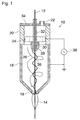
- a plasma nozzle 10 is shown, the essential part of a device for plasma treatment of a fiber 12 forms.
- the fiber 12 can, for example come directly from a spinning machine or from a not shown Coil are pulled off and will, for example, at a speed between 0.05 and 25 m / s, preferably between 5 and 25 m / s coaxial pulled through the plasma nozzle 10. It runs through an out of the Plasma nozzle 10 emerging free plasma 14 and is by the action of this Plasma pretreated evenly over its entire circumference, for example to increase the wettability with liquids.
- the plasma nozzle 10 has a nozzle tube 16 made of electrically conductive material on, which also forms an outer electrode and towards an outlet 18 rejuvenated.
- a ceramic tube 20 is connected upstream of the nozzle tube 16 into which a working gas, for example air under pressure, is fed through an inlet 22 can be initiated.
- a swirl device 24 is arranged in the interior of the ceramic tube 20, which is essentially formed by a disc made of metal, the is provided with helical holes. Through the swirl device 24, the introduced compressed air is swirled so that it is within of the nozzle tube 16 forms a vortex 26 around the continuous fiber 12.
- a pin-shaped inner electrode 28 is electrical with the swirl device 24 connected and protrudes into the interior of the nozzle tube 16.
- the inner electrode 28 has a continuous axial channel 30 into which a guide tube 32 made of ceramic is used.
- the guide tube 32 extends through the Swirl device 24 and through an end wall 34 forming the inlet 22 the plasma nozzle and is traversed by the fiber 12.
- the nozzle tube 16 is grounded and to the inner electrode 28, a voltage is applied using a high-frequency generator 36.
- a corona discharge first occurs, through which an arc discharge is then ignited.
- the resulting arc 38 is entrained by the vortex-shaped air flow and prevented from to go directly to the outer electrode. This is how the arc 38 follows the core of the vertebra 26. If the fiber 12 were not present, the Vortex core and the arc run on the axis of the nozzle tube. Since the vortex-shaped flow is disturbed by the fiber 12, the winds Arc helically around the fiber 12. Due to the intense heat radiation, which arises from the arc 38, the surface of the fiber 12 be thermally treated or pretreated.
- the fiber passes through the free plasma 14, which is due to the twist closes tightly around the fiber.
- Plasma treatment through chemical / physical modification of the material instead of. Due to the conical shape of the nozzle tube and due to a volume expansion the generation of excited plasma accelerates the plasma, so that an elongated plasma flame and a correspondingly intense Treatment of the fiber 12 is achieved.
- the effect and intensity treatment optimized by changing the following parameters the material properties of the fiber 12 and the respective application to be adjusted: throughput speed of the fiber, throughput and chemical Composition of the working gas, voltage and amplitude of the high voltage.
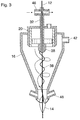
- Figure 2 shows an embodiment in which the nozzle tube 16 of an outer jacket 40 is surrounded, which also tapers towards the outlet. about an inlet 42 is supplied with secondary gas, for example air, into the outer jacket.
- secondary gas for example air
- the throughput of the secondary gas then forms a further parameter, with which the geometry of the plasma can be influenced.
- the secondary gas can possibly also in the same direction or in the opposite direction to the primary working gas are twisted and at the same time causes cooling of the nozzle tube 16. If necessary can by appropriate chemical composition of the secondary gas chemical treatment or coating of the fiber 12 is also achieved become.
- a comparable effect can also be achieved with the arrangement according to FIG. 3, in which the nozzle tube 16 has a longer conical section and an inlet in its upper cylindrical part surrounding the ceramic tube 20 42 has, by the secondary gas swirled or unswirled directly into the Nozzle tube can be fed.
- the guide tube 32 is upstream in this embodiment Plasma nozzle 10 connected to a cross line 46, the compressed air with high Speed is flowed through.
- the fiber 12 through channel of the guide tube 32 according to the jet pump principle creates a negative pressure.
- the section of the guide tube 32 between the transverse line 46 and the mouth in the inner electrode 28 are formed such an air flow that goes up, i.e. the direction of movement of the fiber 12 is directed in the opposite direction.
- Figure 3 is also a way to supply a coating gas illustrated for plasma coating of fiber 12.
- nozzle tube 16 in the region of its outlet one or more feeds 48 through which the coating gas is fed directly into the hot plasma zone becomes.
- the supply of the coating gas can also into the free plasma 14. It is also possible to use the coating gas add to the primary gas or the secondary gas. If on the creation of a Vacuum in the guide tube 32 is omitted, the coating gas can also be fed through this guide tube.
- the fiber 12 consists of electrically conductive material or electrically conductive is coated, it must be prevented that the arc 38 directly on the fiber overturns. If the fiber 12 is at ground potential, this can be done about by having the inner electrode 28 grounded and instead the voltage is applied to the nozzle tube 16 and / or the guide tube 32 beyond the inner electrode 28 into the hot plasma zone or even into that Free plasma 14 is extended.
- the method described is suitable for plasma treatment and / or thermal Treatment of rod or filamentary materials, preferably should have a round or approximately round cross-section.
- the Diameter of the treating material can be configured accordingly the plasma nozzle, for example, in the order of 0.1 to 10 mm lie.
Landscapes
- Engineering & Computer Science (AREA)
- Plasma & Fusion (AREA)
- Physics & Mathematics (AREA)
- Chemical & Material Sciences (AREA)
- Spectroscopy & Molecular Physics (AREA)
- Life Sciences & Earth Sciences (AREA)
- General Chemical & Material Sciences (AREA)
- Chemical Kinetics & Catalysis (AREA)
- General Life Sciences & Earth Sciences (AREA)
- Geochemistry & Mineralogy (AREA)
- Materials Engineering (AREA)
- Organic Chemistry (AREA)
- Treatment Of Fiber Materials (AREA)
- Plasma Technology (AREA)
- Physical Or Chemical Processes And Apparatus (AREA)
- Chemical Vapour Deposition (AREA)
Abstract
Description
- Figuren 1 bis 3
- zeigen Prinzipskizzen von Vorrichtungen zur Durchführung des erfindungsgemäßen Verfahrens gemäß unterschiedlichen Ausführungsbeispielen
Claims (10)
- Verfahren zur Plasmabehandlung von stab- oder fadenförmigem Material (12), dadurch gekennzeichnet, daß man das Material (12) koaxial durch eine Plasmadüse (10) hindurchlaufen läßt.
- Verfahren nach Anspruch 1, zur Plasmabeschichtung des Materials (12), dadurch gekennzeichnet, daß man ein Beschichtungsgas in die Plasmadüse (10) oder das von ihr erzeugte Plasma (14) zuführt.
- Verfahren nach Anspruch 1 oder 2, dadurch gekennzeichnet, daß das Arbeitgas in der Plasmadüse (10) verdrallt wird.
- Verfahren nach Anspruch 3, dadurch gekennzeichnet, daß man am äußeren Umfang der drallförmigen Strömung des Arbeitsgases ein Sekundärgas in die Plasmadüse (10) zuführt.
- Verfahren nach Anspruch 3 oder 4, dadurch gekennzeichnet, daß man in der Plasmadüse einen zur Erzeugung des Plasmas dienenden Lichtbogen (38) durch die Verdrallung des Arbeitsgases derart kanalisiert, daß er sich schraubenförmig um das durchlaufende Material (12) windet.
- Verfahren nach einem der vorstehenden Ansprüche, dadurch gekennzeichnet, daß man das Material (12) über ein Führungsrohr (32) in die Plasmadüse (10) einleitet und im Inneren des Führungsrohres (32) einen Unterdruck erzeugt.
- Vorrichtung zur Behandlung von stab- oder fadenförmigem Material (12), mit einer Plasmadüse (10), die ein eine Außenelektrode bildendes Düsenrohr (16) und eine koaxial in dem Düsenrohr angeordnete Innenelektrode (28) aufeist, gekennzeichnet durch einen koaxial in der Innenelektrode (28) ausgebildeten Kanal (30) durch den das Material (12) hindurchführbar ist.
- Vorrichtung nach Anspruch 7, gekennzeichnet durch ein von außen in die Plasmadüse (10) eintretendes und mindestens bis in den Kanal (30) der Innenelektrode (28) reichendes Führungsrohr (32) für das Material (12).
- Vorrichtung nach Anspruch 8, dadurch gekennzeichnet, daß das Führungsrohr (32) aus elektrisch isolierendem Material besteht.
- Vorrichtung nach einem der Ansprüche 7 bis 9, gekennzeichnet durch eine Dralleinrichtung (24) zur Erzeugung einer drallförmigen Strömung des Arbeitsgases In dem Düsenrohr (16).
Applications Claiming Priority (2)
| Application Number | Priority Date | Filing Date | Title |
|---|---|---|---|
| DE19847774A DE19847774C2 (de) | 1998-10-16 | 1998-10-16 | Vorrichtung zur Plasmabehandlung von stab- oder fadenförmigem Material |
| DE19847774 | 1998-10-16 |
Publications (3)
| Publication Number | Publication Date |
|---|---|
| EP0994637A2 true EP0994637A2 (de) | 2000-04-19 |
| EP0994637A3 EP0994637A3 (de) | 2002-10-23 |
| EP0994637B1 EP0994637B1 (de) | 2005-12-14 |
Family
ID=7884706
Family Applications (1)
| Application Number | Title | Priority Date | Filing Date |
|---|---|---|---|
| EP99118618A Expired - Lifetime EP0994637B1 (de) | 1998-10-16 | 1999-09-21 | Verfahren und Vorrichtung zur Plasmabehandlung von stab- oder fadenförmigem Material |
Country Status (4)
| Country | Link |
|---|---|
| US (1) | US6355312B1 (de) |
| EP (1) | EP0994637B1 (de) |
| AT (1) | ATE313240T1 (de) |
| DE (2) | DE19847774C2 (de) |
Cited By (11)
| Publication number | Priority date | Publication date | Assignee | Title |
|---|---|---|---|---|
| DE10219197C1 (de) * | 2002-04-29 | 2003-09-25 | Fh Hildesheim Holzminden Goe | Verfahren und Vorrichtung zur Behandlung der Oberflächen eines Metalldrahts, insbesondere als Beschichtungsvorbehandlung |
| WO2010067306A3 (fr) * | 2008-12-09 | 2010-08-12 | Advanced Machines Sàrl | Dispositif et procédé de génération d'un flux de plasma |
| CN102379163A (zh) * | 2009-04-02 | 2012-03-14 | 莱茵豪森等离子有限公司 | 用于产生成束的等离子体束的方法和射束发生器 |
| DE102012104224A1 (de) | 2012-05-15 | 2013-11-21 | Plasmatreat Gmbh | Vorrichtung und Verfahren zur Behandlung eines Drahts aus leitfähigem Material |
| EP2320715A3 (de) * | 2009-11-06 | 2014-03-26 | Korea Institute of Industrial Technology | System zum Veredeln von UMG-Si unter Verwendung eines Dampf-Plasmabrenners |
| WO2014106577A1 (de) * | 2013-01-04 | 2014-07-10 | Ford-Werke Gmbh | Vorrichtung zum thermischen beschichten einer oberfläche |
| WO2014191012A1 (de) | 2013-05-27 | 2014-12-04 | Plasmatreat Gmbh | Vorrichtung und verfahren zur behandlung eines drahts aus leitfähigem material |
| CN105027685A (zh) * | 2012-11-19 | 2015-11-04 | 阿本兹81-40 | 通过非等温反应等离子体助剂处理两相碎片状或粉状材料的方法和装置 |
| CN109896580A (zh) * | 2017-12-08 | 2019-06-18 | 松下知识产权经营株式会社 | 液体处理装置 |
| CN114192090A (zh) * | 2021-12-01 | 2022-03-18 | 中国科学院合肥物质科学研究院 | 一种基于直流电弧等离子体炬制备氧化锆的装置 |
| CN116157197A (zh) * | 2020-08-03 | 2023-05-23 | 韩国核融合能源研究院 | 控制氮氧化物的方法和装置和制备含氮氧化物的水的方法 |
Families Citing this family (14)
| Publication number | Priority date | Publication date | Assignee | Title |
|---|---|---|---|---|
| US20040011378A1 (en) * | 2001-08-23 | 2004-01-22 | Jackson David P | Surface cleaning and modification processes, methods and apparatus using physicochemically modified dense fluid sprays |
| DE10331608A1 (de) * | 2003-07-12 | 2005-01-27 | Hew-Kabel/Cdt Gmbh & Co. Kg | Verfahren zum Beschichten und/oder partiellen Umspritzen von flexiblem langgestrecktem Gut |
| US20060172081A1 (en) * | 2005-02-02 | 2006-08-03 | Patrick Flinn | Apparatus and method for plasma treating and dispensing an adhesive/sealant onto a part |
| US20070284342A1 (en) * | 2006-06-09 | 2007-12-13 | Morten Jorgensen | Plasma treatment method and apparatus |
| US7547861B2 (en) * | 2006-06-09 | 2009-06-16 | Morten Jorgensen | Vortex generator for plasma treatment |
| DE102007043333B4 (de) | 2007-09-12 | 2011-05-05 | Maschinenfabrik Reinhausen Gmbh | Verfahren zur Behandlung und Untersuchung von Bauteilen |
| DE102009004968B4 (de) * | 2009-01-14 | 2012-09-06 | Reinhausen Plasma Gmbh | Strahlgenerator zur Erzeugung eines gebündelten Plasmastrahls |
| EP2209354B1 (de) * | 2009-01-14 | 2014-04-09 | Reinhausen Plasma GmbH | Strahlgenerator zur Erzeugung eines gebündelten Plasmastrahls |
| US20110121108A1 (en) * | 2009-11-24 | 2011-05-26 | Stephan Rodewald | Plasma polymerization nozzle |
| CN110178449B (zh) * | 2016-12-23 | 2021-07-23 | 等离子体处理有限公司 | 喷嘴组件和用于制造大气等离子体射流的装置 |
| JP6678336B2 (ja) * | 2017-05-11 | 2020-04-08 | パナソニックIpマネジメント株式会社 | 洗濯機すすぎ水浄化装置及び洗濯装置 |
| HUE063134T2 (hu) | 2018-06-22 | 2023-12-28 | Molecular Plasma Group Sa | Tökéletesített eljárás és készülék bevonat szubsztrátumra lerakására atmoszferikus nyomású plazmasugárral |
| CN112744370B (zh) * | 2020-12-30 | 2024-08-20 | 中国航天空气动力技术研究院 | 一种3d打印电弧加热器旋气室 |
| DE102021124953A1 (de) | 2021-09-27 | 2023-03-30 | Plasmatreat Gmbh | Verfahren und vorrichtung zur herstellung eines glasfaserprodukts sowie glasfaserprodukt und dessen verwendung |
Family Cites Families (22)
| Publication number | Priority date | Publication date | Assignee | Title |
|---|---|---|---|---|
| FR1350055A (fr) * | 1962-12-11 | 1964-01-24 | Centre Nat Rech Scient | Perfectionnements à l'injection des gaz dans les chalumeaux à plasma |
| US3211886A (en) * | 1963-05-06 | 1965-10-12 | Gen Electric | Arc-cleaning and arc-plasma generating apparatus |
| DE1919052A1 (de) * | 1969-04-15 | 1970-10-22 | Erdmann Jesnitzer Dr Ing Habil | Verfahren zur Vorwaermung beim Drahtziehen sowie die Rueckbildung des kaltverformten Zustandes von gezogenem Draht |
| GB2144343A (en) * | 1983-08-02 | 1985-03-06 | Standard Telephones Cables Ltd | Optical fibre manufacture |
| EP0142083A3 (de) * | 1983-11-11 | 1987-04-29 | Hoesch Aktiengesellschaft | Verfahren und Einrichtung zum Herstellen metallischer Überzüge |
| JPS6261010A (ja) * | 1985-09-12 | 1987-03-17 | Kokusai Denshin Denwa Co Ltd <Kdd> | 光ファイバの融着接続方法 |
| US4869936A (en) * | 1987-12-28 | 1989-09-26 | Amoco Corporation | Apparatus and process for producing high density thermal spray coatings |
| US5144110A (en) * | 1988-11-04 | 1992-09-01 | Marantz Daniel Richard | Plasma spray gun and method of use |
| US5053246A (en) * | 1990-03-30 | 1991-10-01 | The Goodyear Tire & Rubber Company | Process for the surface treatment of polymers for reinforcement-to-rubber adhesion |
| US5120567A (en) | 1990-05-17 | 1992-06-09 | General Electric Company | Low frequency plasma spray method in which a stable plasma is created by operating a spray gun at less than 1 mhz in a mixture of argon and helium gas |
| US5114738A (en) * | 1990-07-20 | 1992-05-19 | The United States Of America As Represented By The Secretary Of The Army | Direct optical fiber glass formation techniques using chemically and/or physically removable filamentary substrates |
| US5376413A (en) * | 1990-08-22 | 1994-12-27 | Sommer Societe Anonyme | Treatment of textile fibers |
| US5108780A (en) * | 1991-01-28 | 1992-04-28 | Brigham Young University | Enhanced thermoplastic adhesion to fibers by using plasma discharge |
| DE4211167A1 (de) * | 1992-03-31 | 1993-10-07 | Thaelmann Schwermaschbau Veb | Verfahren und Vorrichtung zur kontinuierlichen thermischen Oberflächenbehandlung stab- bzw. strangförmiger Materialien mit metallischer Oberfläche |
| DE4235766C2 (de) * | 1992-10-24 | 1998-11-12 | Agrodyn Hochspannungstechnik G | Koronagenerator |
| US5296670A (en) * | 1992-12-31 | 1994-03-22 | Osram Sylvania Inc. | DC plasma arc generator with erosion control and method of operation |
| US5393955A (en) * | 1993-01-14 | 1995-02-28 | Simmons; Walter N. | Preparation of fullerenes and apparatus therefor |
| US5734144A (en) * | 1993-03-26 | 1998-03-31 | Kabushiki Kaisha Komatsu Seisakusho | Plasma arc welding method and apparatus in which a swirling flow is imparted to a plasma gas to stabilize a plasma arc |
| JPH08124697A (ja) * | 1994-10-20 | 1996-05-17 | Nippon Steel Corp | プラズマトーチ |
| DE19532412C2 (de) * | 1995-09-01 | 1999-09-30 | Agrodyn Hochspannungstechnik G | Vorrichtung zur Oberflächen-Vorbehandlung von Werkstücken |
| US6080954A (en) * | 1996-12-27 | 2000-06-27 | Neturen Co., Ltd | Heat treatment method and apparatus using thermal plasma, and heat treated substance produced thereby |
| DE19742442B4 (de) * | 1997-09-26 | 2005-07-07 | Raantec Gmbh & Co. Kg | Vorrichtung zum Verschweißen von Kunststoff-Folien |
-
1998
- 1998-10-16 DE DE19847774A patent/DE19847774C2/de not_active Expired - Fee Related
-
1999
- 1999-09-21 AT AT99118618T patent/ATE313240T1/de active
- 1999-09-21 EP EP99118618A patent/EP0994637B1/de not_active Expired - Lifetime
- 1999-09-21 DE DE59912921T patent/DE59912921D1/de not_active Expired - Lifetime
- 1999-10-15 US US09/418,561 patent/US6355312B1/en not_active Expired - Lifetime
Cited By (21)
| Publication number | Priority date | Publication date | Assignee | Title |
|---|---|---|---|---|
| DE10219197C1 (de) * | 2002-04-29 | 2003-09-25 | Fh Hildesheim Holzminden Goe | Verfahren und Vorrichtung zur Behandlung der Oberflächen eines Metalldrahts, insbesondere als Beschichtungsvorbehandlung |
| US8847101B2 (en) | 2008-12-09 | 2014-09-30 | Advanced Machine Sarl | Device and method for generating a plasma flow |
| WO2010067306A3 (fr) * | 2008-12-09 | 2010-08-12 | Advanced Machines Sàrl | Dispositif et procédé de génération d'un flux de plasma |
| EP2613614A1 (de) * | 2008-12-09 | 2013-07-10 | Advanced Machines Sàrl | Vorrichtung zur Erzeugung eines Plasmaflusses |
| CN102379163A (zh) * | 2009-04-02 | 2012-03-14 | 莱茵豪森等离子有限公司 | 用于产生成束的等离子体束的方法和射束发生器 |
| CN102379163B (zh) * | 2009-04-02 | 2014-06-11 | 莱茵豪森等离子有限公司 | 用于产生成束的等离子体束的方法和射束发生器 |
| EP2320715A3 (de) * | 2009-11-06 | 2014-03-26 | Korea Institute of Industrial Technology | System zum Veredeln von UMG-Si unter Verwendung eines Dampf-Plasmabrenners |
| US8790584B2 (en) | 2009-11-06 | 2014-07-29 | Korea Institute Of Industrial Technology | System for refining UMG Si using steam plasma torch |
| DE102012104224A1 (de) | 2012-05-15 | 2013-11-21 | Plasmatreat Gmbh | Vorrichtung und Verfahren zur Behandlung eines Drahts aus leitfähigem Material |
| CN105027685B (zh) * | 2012-11-19 | 2019-04-05 | 阿本兹 81-40 | 通过非等温反应等离子体助剂处理两相碎片状或粉状材料的方法和装置 |
| CN105027685A (zh) * | 2012-11-19 | 2015-11-04 | 阿本兹81-40 | 通过非等温反应等离子体助剂处理两相碎片状或粉状材料的方法和装置 |
| CN104955582A (zh) * | 2013-01-04 | 2015-09-30 | 福特全球技术公司 | 用于热涂覆表面的装置 |
| CN104955582B (zh) * | 2013-01-04 | 2017-05-17 | 福特全球技术公司 | 用于热涂覆表面的装置 |
| US10124354B2 (en) | 2013-01-04 | 2018-11-13 | Ford Global Technologies, Llc | Plasma nozzle for thermal spraying using a consumable wire |
| WO2014106577A1 (de) * | 2013-01-04 | 2014-07-10 | Ford-Werke Gmbh | Vorrichtung zum thermischen beschichten einer oberfläche |
| WO2014191012A1 (de) | 2013-05-27 | 2014-12-04 | Plasmatreat Gmbh | Vorrichtung und verfahren zur behandlung eines drahts aus leitfähigem material |
| CN109896580A (zh) * | 2017-12-08 | 2019-06-18 | 松下知识产权经营株式会社 | 液体处理装置 |
| CN109896580B (zh) * | 2017-12-08 | 2021-10-15 | 松下知识产权经营株式会社 | 液体处理装置 |
| CN116157197A (zh) * | 2020-08-03 | 2023-05-23 | 韩国核融合能源研究院 | 控制氮氧化物的方法和装置和制备含氮氧化物的水的方法 |
| CN114192090A (zh) * | 2021-12-01 | 2022-03-18 | 中国科学院合肥物质科学研究院 | 一种基于直流电弧等离子体炬制备氧化锆的装置 |
| CN114192090B (zh) * | 2021-12-01 | 2023-08-25 | 中国科学院合肥物质科学研究院 | 一种基于直流电弧等离子体炬制备氧化锆的装置 |
Also Published As
| Publication number | Publication date |
|---|---|
| DE19847774A1 (de) | 2000-05-04 |
| DE59912921D1 (de) | 2006-01-19 |
| US6355312B1 (en) | 2002-03-12 |
| EP0994637A3 (de) | 2002-10-23 |
| DE19847774C2 (de) | 2002-10-17 |
| EP0994637B1 (de) | 2005-12-14 |
| ATE313240T1 (de) | 2005-12-15 |
Similar Documents
| Publication | Publication Date | Title |
|---|---|---|
| EP0994637B1 (de) | Verfahren und Vorrichtung zur Plasmabehandlung von stab- oder fadenförmigem Material | |
| EP0761415B1 (de) | Verfahren zur Erhöhung der Benetzbarkeit der Oberfläche von Werkstücken | |
| EP1236380B1 (de) | Plasmadüse | |
| DE102007011235A1 (de) | Verfahren und Vorrichtung zur Behandlung einer Oberfläche eines Werkstückes | |
| DE4340224C2 (de) | Einrichtung zum Erzeugen von Plasma mittels Mikrowellenstrahlung | |
| EP3387886B1 (de) | Vorrichtung zum erzeugen eines atmosphärischen plasmastrahls und verfahren zur behandlung der oberfläche eines werkstücks | |
| DE10145131B4 (de) | Vorrichtung zum Erzeugen eines Aktivgasstrahls | |
| DE29911974U1 (de) | Plasmadüse | |
| EP1335641B1 (de) | Plasmadüse | |
| EP2382460B1 (de) | Verfahren und vorrichtung zur detektion von ionisierbaren gasen | |
| DE102009015510B4 (de) | Verfahren und Strahlgenerator zur Erzeugung eines gebündelten Plasmastrahls | |
| EP0941145B1 (de) | Pulversprüheinrichtung | |
| DE102005018926B4 (de) | Verfahren und Plasmadüse zum Erzeugen eines mittels hochfrequenter Hochspannung erzeugten atmosphärischen Plasmastrahls umfassend eine Vorrichtung jeweils zur Charakterisierung einer Oberfläche eines Werkstückes | |
| US3282768A (en) | Apparatus for blooming filter tow | |
| WO2008061602A1 (de) | Verfahren und vorrichtung zum erzeugen eines plasmas und anwendungen des plasmas | |
| DE202009000537U1 (de) | Strahlgenerator zur Erzeugung eines gebündelten Plasmastrahls | |
| EP2209354B1 (de) | Strahlgenerator zur Erzeugung eines gebündelten Plasmastrahls | |
| DE3733492A1 (de) | Vorrichtung zur behandlung von oberflaechen mittels eines ionisierten gasstromes | |
| EP2532214B1 (de) | Hohltrichterförmiger plasmagenerator | |
| DE102009004968B4 (de) | Strahlgenerator zur Erzeugung eines gebündelten Plasmastrahls | |
| EP0707175A1 (de) | Düse für eine Verbrennungsvorrichtung | |
| DE19542863A1 (de) | Pulversprüheinrichtung | |
| DE10061828B4 (de) | Verfahren zum Einbringen von Material in einen Plasmastrahl und Plasmadüse zur Durchführung des Verfahrens | |
| DE102005043278B4 (de) | Verfahren und Vorrichtung zum Erzeugen eines sich ausdehnenden, diffusen Mikrowellenplasmas | |
| DE1284952B (de) | Verfahren und Vorrichtung zur Durchfuehrung von Gasphasenreaktionen in elektrischen Entladungen |
Legal Events
| Date | Code | Title | Description |
|---|---|---|---|
| PUAI | Public reference made under article 153(3) epc to a published international application that has entered the european phase |
Free format text: ORIGINAL CODE: 0009012 |
|
| AK | Designated contracting states |
Kind code of ref document: A2 Designated state(s): AT BE CH CY DE DK ES FI FR GB GR IE IT LI LU MC NL PT SE |
|
| AX | Request for extension of the european patent |
Free format text: AL;LT;LV;MK;RO;SI |
|
| PUAL | Search report despatched |
Free format text: ORIGINAL CODE: 0009013 |
|
| AK | Designated contracting states |
Kind code of ref document: A3 Designated state(s): AT BE CH CY DE DK ES FI FR GB GR IE IT LI LU MC NL PT SE |
|
| AX | Request for extension of the european patent |
Free format text: AL;LT;LV;MK;RO;SI |
|
| RIC1 | Information provided on ipc code assigned before grant |
Free format text: 7H 05H 1/48 A |
|
| 17P | Request for examination filed |
Effective date: 20030201 |
|
| AKX | Designation fees paid |
Designated state(s): AT BE CH CY DE DK ES FI FR GB GR IE IT LI LU MC NL PT SE |
|
| 17Q | First examination report despatched |
Effective date: 20040705 |
|
| RTI1 | Title (correction) |
Free format text: METHOD AND DEVICE FOR PLASMA TREATMENT OF BAR OR WIRE SHAPED MATERIAL |
|
| GRAP | Despatch of communication of intention to grant a patent |
Free format text: ORIGINAL CODE: EPIDOSNIGR1 |
|
| GRAS | Grant fee paid |
Free format text: ORIGINAL CODE: EPIDOSNIGR3 |
|
| GRAA | (expected) grant |
Free format text: ORIGINAL CODE: 0009210 |
|
| AK | Designated contracting states |
Kind code of ref document: B1 Designated state(s): AT BE CH CY DE DK ES FI FR GB GR IE IT LI LU MC NL PT SE |
|
| PG25 | Lapsed in a contracting state [announced via postgrant information from national office to epo] |
Ref country code: NL Free format text: LAPSE BECAUSE OF FAILURE TO SUBMIT A TRANSLATION OF THE DESCRIPTION OR TO PAY THE FEE WITHIN THE PRESCRIBED TIME-LIMIT Effective date: 20051214 Ref country code: FI Free format text: LAPSE BECAUSE OF FAILURE TO SUBMIT A TRANSLATION OF THE DESCRIPTION OR TO PAY THE FEE WITHIN THE PRESCRIBED TIME-LIMIT Effective date: 20051214 |
|
| REG | Reference to a national code |
Ref country code: GB Ref legal event code: FG4D Free format text: NOT ENGLISH |
|
| REG | Reference to a national code |
Ref country code: CH Ref legal event code: EP |
|
| REG | Reference to a national code |
Ref country code: IE Ref legal event code: FG4D Free format text: LANGUAGE OF EP DOCUMENT: GERMAN |
|
| REF | Corresponds to: |
Ref document number: 59912921 Country of ref document: DE Date of ref document: 20060119 Kind code of ref document: P |
|
| PG25 | Lapsed in a contracting state [announced via postgrant information from national office to epo] |
Ref country code: SE Free format text: LAPSE BECAUSE OF FAILURE TO SUBMIT A TRANSLATION OF THE DESCRIPTION OR TO PAY THE FEE WITHIN THE PRESCRIBED TIME-LIMIT Effective date: 20060314 Ref country code: GR Free format text: LAPSE BECAUSE OF FAILURE TO SUBMIT A TRANSLATION OF THE DESCRIPTION OR TO PAY THE FEE WITHIN THE PRESCRIBED TIME-LIMIT Effective date: 20060314 Ref country code: DK Free format text: LAPSE BECAUSE OF FAILURE TO SUBMIT A TRANSLATION OF THE DESCRIPTION OR TO PAY THE FEE WITHIN THE PRESCRIBED TIME-LIMIT Effective date: 20060314 |
|
| GBT | Gb: translation of ep patent filed (gb section 77(6)(a)/1977) |
Effective date: 20060220 |
|
| PG25 | Lapsed in a contracting state [announced via postgrant information from national office to epo] |
Ref country code: ES Free format text: LAPSE BECAUSE OF FAILURE TO SUBMIT A TRANSLATION OF THE DESCRIPTION OR TO PAY THE FEE WITHIN THE PRESCRIBED TIME-LIMIT Effective date: 20060325 |
|
| PG25 | Lapsed in a contracting state [announced via postgrant information from national office to epo] |
Ref country code: PT Free format text: LAPSE BECAUSE OF FAILURE TO SUBMIT A TRANSLATION OF THE DESCRIPTION OR TO PAY THE FEE WITHIN THE PRESCRIBED TIME-LIMIT Effective date: 20060515 |
|
| NLV1 | Nl: lapsed or annulled due to failure to fulfill the requirements of art. 29p and 29m of the patents act | ||
| ET | Fr: translation filed | ||
| PG25 | Lapsed in a contracting state [announced via postgrant information from national office to epo] |
Ref country code: MC Free format text: LAPSE BECAUSE OF NON-PAYMENT OF DUE FEES Effective date: 20060930 Ref country code: LI Free format text: LAPSE BECAUSE OF NON-PAYMENT OF DUE FEES Effective date: 20060930 Ref country code: CH Free format text: LAPSE BECAUSE OF NON-PAYMENT OF DUE FEES Effective date: 20060930 Ref country code: BE Free format text: LAPSE BECAUSE OF NON-PAYMENT OF DUE FEES Effective date: 20060930 |
|
| PLBE | No opposition filed within time limit |
Free format text: ORIGINAL CODE: 0009261 |
|
| STAA | Information on the status of an ep patent application or granted ep patent |
Free format text: STATUS: NO OPPOSITION FILED WITHIN TIME LIMIT |
|
| 26N | No opposition filed |
Effective date: 20060915 |
|
| REG | Reference to a national code |
Ref country code: CH Ref legal event code: PL |
|
| BERE | Be: lapsed |
Owner name: BUSKE, CHRISTIAN Effective date: 20060930 Owner name: FORNSEL, PETER Effective date: 20060930 |
|
| PG25 | Lapsed in a contracting state [announced via postgrant information from national office to epo] |
Ref country code: LU Free format text: LAPSE BECAUSE OF NON-PAYMENT OF DUE FEES Effective date: 20060921 |
|
| PG25 | Lapsed in a contracting state [announced via postgrant information from national office to epo] |
Ref country code: CY Free format text: LAPSE BECAUSE OF FAILURE TO SUBMIT A TRANSLATION OF THE DESCRIPTION OR TO PAY THE FEE WITHIN THE PRESCRIBED TIME-LIMIT Effective date: 20051214 |
|
| REG | Reference to a national code |
Ref country code: FR Ref legal event code: PLFP Year of fee payment: 18 |
|
| PGFP | Annual fee paid to national office [announced via postgrant information from national office to epo] |
Ref country code: IE Payment date: 20160831 Year of fee payment: 18 Ref country code: GB Payment date: 20160923 Year of fee payment: 18 Ref country code: DE Payment date: 20160923 Year of fee payment: 18 |
|
| PGFP | Annual fee paid to national office [announced via postgrant information from national office to epo] |
Ref country code: FR Payment date: 20160923 Year of fee payment: 18 Ref country code: AT Payment date: 20160926 Year of fee payment: 18 |
|
| PGFP | Annual fee paid to national office [announced via postgrant information from national office to epo] |
Ref country code: IT Payment date: 20160926 Year of fee payment: 18 |
|
| REG | Reference to a national code |
Ref country code: DE Ref legal event code: R119 Ref document number: 59912921 Country of ref document: DE |
|
| REG | Reference to a national code |
Ref country code: AT Ref legal event code: MM01 Ref document number: 313240 Country of ref document: AT Kind code of ref document: T Effective date: 20170921 |
|
| GBPC | Gb: european patent ceased through non-payment of renewal fee |
Effective date: 20170921 |
|
| REG | Reference to a national code |
Ref country code: IE Ref legal event code: MM4A |
|
| REG | Reference to a national code |
Ref country code: FR Ref legal event code: ST Effective date: 20180531 |
|
| PG25 | Lapsed in a contracting state [announced via postgrant information from national office to epo] |
Ref country code: IE Free format text: LAPSE BECAUSE OF NON-PAYMENT OF DUE FEES Effective date: 20170921 Ref country code: DE Free format text: LAPSE BECAUSE OF NON-PAYMENT OF DUE FEES Effective date: 20180404 Ref country code: GB Free format text: LAPSE BECAUSE OF NON-PAYMENT OF DUE FEES Effective date: 20170921 |
|
| PG25 | Lapsed in a contracting state [announced via postgrant information from national office to epo] |
Ref country code: IT Free format text: LAPSE BECAUSE OF NON-PAYMENT OF DUE FEES Effective date: 20170921 Ref country code: FR Free format text: LAPSE BECAUSE OF NON-PAYMENT OF DUE FEES Effective date: 20171002 Ref country code: AT Free format text: LAPSE BECAUSE OF NON-PAYMENT OF DUE FEES Effective date: 20170921 |