EP0992374A1 - Système de suspension à deux entrées utilisant un dispositif ressort/amortisseur commun - Google Patents
Système de suspension à deux entrées utilisant un dispositif ressort/amortisseur commun Download PDFInfo
- Publication number
- EP0992374A1 EP0992374A1 EP99650093A EP99650093A EP0992374A1 EP 0992374 A1 EP0992374 A1 EP 0992374A1 EP 99650093 A EP99650093 A EP 99650093A EP 99650093 A EP99650093 A EP 99650093A EP 0992374 A1 EP0992374 A1 EP 0992374A1
- Authority
- EP
- European Patent Office
- Prior art keywords
- arm
- swing
- input
- frame member
- suspension
- Prior art date
- Legal status (The legal status is an assumption and is not a legal conclusion. Google has not performed a legal analysis and makes no representation as to the accuracy of the status listed.)
- Withdrawn
Links
Images


Classifications
-
- B—PERFORMING OPERATIONS; TRANSPORTING
- B60—VEHICLES IN GENERAL
- B60G—VEHICLE SUSPENSION ARRANGEMENTS
- B60G21/00—Interconnection systems for two or more resiliently-suspended wheels, e.g. for stabilising a vehicle body with respect to acceleration, deceleration or centrifugal forces
- B60G21/02—Interconnection systems for two or more resiliently-suspended wheels, e.g. for stabilising a vehicle body with respect to acceleration, deceleration or centrifugal forces permanently interconnected
- B60G21/04—Interconnection systems for two or more resiliently-suspended wheels, e.g. for stabilising a vehicle body with respect to acceleration, deceleration or centrifugal forces permanently interconnected mechanically
-
- B—PERFORMING OPERATIONS; TRANSPORTING
- B60—VEHICLES IN GENERAL
- B60G—VEHICLE SUSPENSION ARRANGEMENTS
- B60G15/00—Resilient suspensions characterised by arrangement, location or type of combined spring and vibration damper, e.g. telescopic type
- B60G15/02—Resilient suspensions characterised by arrangement, location or type of combined spring and vibration damper, e.g. telescopic type having mechanical spring
- B60G15/06—Resilient suspensions characterised by arrangement, location or type of combined spring and vibration damper, e.g. telescopic type having mechanical spring and fluid damper
- B60G15/062—Resilient suspensions characterised by arrangement, location or type of combined spring and vibration damper, e.g. telescopic type having mechanical spring and fluid damper the spring being arranged around the damper
-
- B—PERFORMING OPERATIONS; TRANSPORTING
- B60—VEHICLES IN GENERAL
- B60G—VEHICLE SUSPENSION ARRANGEMENTS
- B60G17/00—Resilient suspensions having means for adjusting the spring or vibration-damper characteristics, for regulating the distance between a supporting surface and a sprung part of vehicle or for locking suspension during use to meet varying vehicular or surface conditions, e.g. due to speed or load
- B60G17/02—Spring characteristics, e.g. mechanical springs and mechanical adjusting means
- B60G17/033—Spring characteristics, e.g. mechanical springs and mechanical adjusting means characterised by regulating means acting on more than one spring
-
- B—PERFORMING OPERATIONS; TRANSPORTING
- B62—LAND VEHICLES FOR TRAVELLING OTHERWISE THAN ON RAILS
- B62K—CYCLES; CYCLE FRAMES; CYCLE STEERING DEVICES; RIDER-OPERATED TERMINAL CONTROLS SPECIALLY ADAPTED FOR CYCLES; CYCLE AXLE SUSPENSIONS; CYCLE SIDE-CARS, FORECARS, OR THE LIKE
- B62K25/00—Axle suspensions
- B62K25/04—Axle suspensions for mounting axles resiliently on cycle frame or fork
- B62K25/28—Axle suspensions for mounting axles resiliently on cycle frame or fork with pivoted chain-stay
- B62K25/283—Axle suspensions for mounting axles resiliently on cycle frame or fork with pivoted chain-stay for cycles without a pedal crank, e.g. motorcycles
-
- B—PERFORMING OPERATIONS; TRANSPORTING
- B60—VEHICLES IN GENERAL
- B60G—VEHICLE SUSPENSION ARRANGEMENTS
- B60G2202/00—Indexing codes relating to the type of spring, damper or actuator
- B60G2202/30—Spring/Damper and/or actuator Units
- B60G2202/31—Spring/Damper and/or actuator Units with the spring arranged around the damper, e.g. MacPherson strut
- B60G2202/312—The spring being a wound spring
-
- B—PERFORMING OPERATIONS; TRANSPORTING
- B60—VEHICLES IN GENERAL
- B60G—VEHICLE SUSPENSION ARRANGEMENTS
- B60G2204/00—Indexing codes related to suspensions per se or to auxiliary parts
- B60G2204/10—Mounting of suspension elements
- B60G2204/12—Mounting of springs or dampers
- B60G2204/129—Damper mount on wheel suspension or knuckle
-
- B—PERFORMING OPERATIONS; TRANSPORTING
- B60—VEHICLES IN GENERAL
- B60G—VEHICLE SUSPENSION ARRANGEMENTS
- B60G2204/00—Indexing codes related to suspensions per se or to auxiliary parts
- B60G2204/40—Auxiliary suspension parts; Adjustment of suspensions
- B60G2204/421—Pivoted lever mechanisms for mounting suspension elements, e.g. Watt linkage
-
- B—PERFORMING OPERATIONS; TRANSPORTING
- B60—VEHICLES IN GENERAL
- B60G—VEHICLE SUSPENSION ARRANGEMENTS
- B60G2204/00—Indexing codes related to suspensions per se or to auxiliary parts
- B60G2204/40—Auxiliary suspension parts; Adjustment of suspensions
- B60G2204/422—Links for mounting suspension elements
-
- B—PERFORMING OPERATIONS; TRANSPORTING
- B60—VEHICLES IN GENERAL
- B60G—VEHICLE SUSPENSION ARRANGEMENTS
- B60G2204/00—Indexing codes related to suspensions per se or to auxiliary parts
- B60G2204/40—Auxiliary suspension parts; Adjustment of suspensions
- B60G2204/423—Rails, tubes, or the like, for guiding the movement of suspension elements
- B60G2204/4232—Sliding mounts
-
- B—PERFORMING OPERATIONS; TRANSPORTING
- B60—VEHICLES IN GENERAL
- B60G—VEHICLE SUSPENSION ARRANGEMENTS
- B60G2204/00—Indexing codes related to suspensions per se or to auxiliary parts
- B60G2204/80—Interactive suspensions; arrangement affecting more than one suspension unit
-
- B—PERFORMING OPERATIONS; TRANSPORTING
- B60—VEHICLES IN GENERAL
- B60G—VEHICLE SUSPENSION ARRANGEMENTS
- B60G2204/00—Indexing codes related to suspensions per se or to auxiliary parts
- B60G2204/80—Interactive suspensions; arrangement affecting more than one suspension unit
- B60G2204/81—Interactive suspensions; arrangement affecting more than one suspension unit front and rear unit
-
- B—PERFORMING OPERATIONS; TRANSPORTING
- B60—VEHICLES IN GENERAL
- B60G—VEHICLE SUSPENSION ARRANGEMENTS
- B60G2204/00—Indexing codes related to suspensions per se or to auxiliary parts
- B60G2204/80—Interactive suspensions; arrangement affecting more than one suspension unit
- B60G2204/82—Interactive suspensions; arrangement affecting more than one suspension unit left and right unit on same axle
-
- B—PERFORMING OPERATIONS; TRANSPORTING
- B60—VEHICLES IN GENERAL
- B60G—VEHICLE SUSPENSION ARRANGEMENTS
- B60G2204/00—Indexing codes related to suspensions per se or to auxiliary parts
- B60G2204/80—Interactive suspensions; arrangement affecting more than one suspension unit
- B60G2204/83—Type of interconnection
- B60G2204/8302—Mechanical
-
- B—PERFORMING OPERATIONS; TRANSPORTING
- B60—VEHICLES IN GENERAL
- B60G—VEHICLE SUSPENSION ARRANGEMENTS
- B60G2204/00—Indexing codes related to suspensions per se or to auxiliary parts
- B60G2204/80—Interactive suspensions; arrangement affecting more than one suspension unit
- B60G2204/83—Type of interconnection
- B60G2204/8306—Permanent; Continuous
-
- B—PERFORMING OPERATIONS; TRANSPORTING
- B60—VEHICLES IN GENERAL
- B60G—VEHICLE SUSPENSION ARRANGEMENTS
- B60G2300/00—Indexing codes relating to the type of vehicle
- B60G2300/12—Cycles; Motorcycles
Definitions
- the present invention generally refers to a suspension system wherein two inputs are applied to a common load suspension device.
- the system of the invention may be applied to land vehicles: more particularly to bicycles, motor-cycles and motor-cars.
- the suspension system may serve to isolate the seat and handlebars from each of the front or back wheels.
- the system may be applied to either or both the front and/or rear axles or to the left- and right-hand side pairs of wheels.
- the shock-absorber function within the context of the present invention, is related to dampening movement transmitted from a movable part to another part supported thereon or otherwise connected thereto.
- the function of the spring is to maintain support of the movable part at a predetermined height or distance from the other part, by resiliently restoring the movable part back to its original placement once the external force causing movement thereof has ceased.
- Vehicles generally have separate suspension devices comprising springs or springs and shock absorbers in combination, for each wheel or axle end.
- Such devices are technically well developed and relatively costly.
- the weight of the suspension device is also a relevant factor.
- each half-spring is considered as a separate resilient element pertinent to a separate wheel or wheel system.
- Such separate devices are even more apparent in two-wheel vehicles.
- Most motor-cycles and some bicycles supplied with full suspension means use a wheel suspension system provided with a telescopically coupled sliding tube and a fork leg forming a suspension assembly with a shock absorber assembly.
- the size of the conventional tube/fork system requires over-dimensioning to resist strong shocks which tend to bend the arrangement. Another consideration is that the optimum angle of direction does not coincide with the optimum angle of operation.
- Pedalling is the cause of a further problem in the case of bicycles.
- Many rear suspensions are made with the pivot point at the same height as the rear wheel axle and/or about the crank assembly center. As soon as the rear axle goes above the pivot point, the chain force tends to pull the suspension into further compression. This exaggerates the suspension and creates a sagging effect that can be felt when pedalling. Furthermore, there is a loss of pedalling energy.
- the pivot point of many suspension units has been raised above the front chain ring. By doing this, the sag effect and the pull on the suspension is reduced or eliminated, such as suggested in US patent 5,725,227 or in US patent 5,685,553.
- US patents 5,791,674 and 5,452,910 disclose articulated systems wherein the rear swing arm trasero does not follow a circular path through a pivot, thereby reducing forces transmitted to the frame by pot-holes and reducing the ziz-zag effect caused by pedalling. This effect is also addressed by US patent 5,785,339 which discloses a more complex system.
- an object of the present invention is to provide a suspension system wherein two separate input nodes may be independently coupled to a vehicle frame using a single suspension device.
- Another object of the present invention is a system for use in a two-wheel vehicle or cycle for providing front and rear wheel suspension to the cycle frame by means of a single spring means, with or without complementary shock absorbing means.
- a further object of the present invention is a system for use in a multiple two-wheel axle vehicle for providing independent suspension for each wheel of an axle thereof to a vehicle chassis or body through a common spring and shock absorber means.
- Yet a further object of the invention is to provide a simpler and more economical suspension system.
- the invention provides a suspension system as claimed in claim 1, use of such a system as claimed in claim 7, and a vehicle as claimed in claim 10.
- the suspension system of the invention generally comprises a frame member to which a pair of separate input nodes are pivotably connected such as by means of a pair of input swing-arms.
- the frame member forms part of a generally static load system which includes the means accommodating the vehicle passengers in transit.
- the suspension system further comprises a common swing-arm pivoting on a slider mounted to said frame member, such that the swing-arm may pivot and translate in a predetermined direction in relation to the frame member.
- the slider is coupled to the frame member by means of a suspension device which may include a resilient member or a resilient/shock absorber combination.
- the swing-arm includes two further pivots on each side of the slider pivot for coupling respective link arms to each of said nodes in a configuration such that an external force disturbing one of said nodes causes the common swing-arm to tilt substantially about the link-arm pivot corresponding to the other, undisturbed node, thereby urging the slider against the suspension device.
- the mechanism essentially formed by the link arms, the common swing arm and the slider provides substantially independent suspension between the frame member and each of the input nodes.
- the present invention further identifies two inherently stable link arm configurations in particular.
- the slider is located on the frame arm above the pivot connections between the frame arm and the pair of input swing-arms.
- the link-arms may cross-over to connect each node to the opposite end of the common swing-arm.
- the slider is located on the frame arm below the pivot connections between the frame arm and the pair of input swing-arms.
- the link-arms connect each node to the end of the common swing-arm on the same side of the frame member as the node.
- a condition for unaided stability is that the link-arm configuration be such that a positive (upward) disturbance at one node tends to reduce the angle between the driven link-arm and the common swing-arm, i.e. urges the common swing-arm to align with the driven link-arm.
- the present invention is, inter alia, applicable to two-wheel vehicles or cycles wherein the frame member supports the seat.
- the front and back wheel axles may be considered as the input nodes.
- the fork mounting the back wheel axle is adapted as a rear input swing-arm directly pivoted to the frame member.
- the front fork is generally rigidly connected to the second input swing-arm, the rear end of which is pivotably connected to the rear swing-arm/fork.
- the handlebar of the vehicle is not rigidly attached to the front wheel fork as in conventional bicycles and motor-cycles but is connected to the seat.
- a first embodiment of the suspension system is shown in figure 1 in a relative unloaded state.
- a load L requiring independent suspension from two separate inputs I A and I B is supported by a reference frame member 11.
- the load L may comprise a plurality of discrete components and may be rigidly attached to the frame member.
- the load L appears centred on the frame member 11.
- the load L may alternatively be eccentric relative to the frame member.
- a pair of pivots 13A and 13B at the bottom end of the frame member 11 connect the latter to a pair of input swing-arms 15A and 15B the free ends of which incorporate the input nodes I A and I B .
- the input nodes I are depicted in the drawings at a certain point on their associated swing-arm 15 (alphabetical suffices A, B are often omitted herein when generalising), the input I may be applied at any point or distributed over multiple points of the input swing-arm 15 spaced from the frame pivot 13.
- pivot connections 13A and 13B are shown in the drawings, however they may be combined into a single triple-pivot connection.
- connection of an input swing-arm 15 to the frame member 11 need not necessarily be direct.
- bottom is used herein in a relative sense consistent with the preferred vehicle applications of the invention described hereinafter.
- a "positive" disturbance force applied to any one of said nodes I A or I B is assumed to have a component in the "upward” direction.
- the suspension system of the invention is disclosed lying generally in an ideal vertical plane, the system may lie eventually in a horizontal plane according to a particular application requirement, hence the use of the "positive” rather than upward.
- computer simulation has shown that the inputs may be briefly negative (such as going down a step), however the magnitudes thereof are smaller compared to the positive inputs and have no substantial impact on design considerations.
- the frame member 11 is attached to one side of a suspension device 17 including a resilient component or spring S.
- a shock absorber M is added in combination, e.g. in parallel, to the spring S. Both components S and M may be of conventional design.
- the other, movable side of the suspension device 17 is attached to a slider 19 slidably mounted to the frame member 11.
- the slider 19 features a pivot 21 to which a swing-arm 23 is mounted, such that the swing-arm 23 may slide up and down the frame member 11 and rotate about this locus.
- the slider 19 is driven in this manner by a linkage system 24 according to the invention comprising a pair of link-arms 25 arranged as depicted in figure 1.
- a linkage system 24 comprising a pair of link-arms 25 arranged as depicted in figure 1.
- the other link-arm 25B has a pivot connection 27B to the swing-arm 15B and another pivot connection 29B to the common swing-arm 23.
- the frame member 11 is depicted as a bar-shaped member, it is in no way restricted to this shape and may have a different shape as required by a specific application.
- the slider function may be embodied by an elongated hole formed in a plate-shape frame member to hold central pivot means 21.
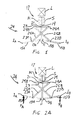
- Figure 2A illustrates the system response to a balanced input applied at both nodes I A and I B simultaneously.
- Each link arm 25 applies on the corresponding end of the common swing-arm 23 a vertical force component directed upwards and a vertical force component directed inwards, i.e. towards the central pivot 21.
- one of the nodes I B is subjected to a positive disturbance F B ⁇ F A .
- the swing-arm 15B pivots upwards and, through rigid link-arm 25B, pushes the opposite side of common swing-arm 23, causing the latter to rotate since there is no countertorque on the other end thereof.
- the common swing-arm 23 rotates in a direction which tends to align it with the driving link-arm 25B.
- the common swing-arm 23 substantially rotates on the pivot 29A at its opposite end, thereby dragging the slider 19 upwards and urging the required reaction from the suspension device the suspension device 17 to cushion the effect of the input F B on the load and restore the normal position thereof.
- Figure 3 illustrates an alternative embodiment useful for such applications.
- the slider 19 is located on the bottom part of the frame member 11 and a different linkage arrangement 24' is required to ensure an inherent stable suspension system.
- the stability condition may be expressed as that the link-arms 25 should be arranged such that, in response to an external disturbance at one of the nodes I. the common swing-arm 23 tends to align itself, or close the angle, with the disturbed link-arm 25. To satisfy this condition, each link-arm should be connected to the end of the common swing-arm 23 on the same side of the associated input swing-arm 15 relative to the frame member 11.
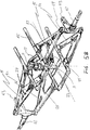
- FIG. 4 refers to a particular application of the suspension system of the invention to a bicycle or motor-cycle. For ease of illustration and clarity, only the relevant parts of the cycle are represented.
- the cycle comprises a frame member 11 including means 31 for supporting a seat on top and, in the case of a bicycle, means 33 below for holding the pedals.
- a slider 19 is mounted to the frame member 11 and a spring S between the slider 19 and an upper stop 35 on the frame member 11.
- a front fork 37 is conventionally adapted to hold a wheel and is retained inside a tubular housing 39 allowing the wheel to turn sideways by means of handlebars 41 (represented schematically in figure 4), further reference to which is made hereinafter.
- the fork housing 39 is rigidly attached to a front swing-arm member 15F such that disturbances returned by the front wheel (the axle of which may be considered as one of the input nodes IF) are transferred directly to the arm 15F.
- the rear swing-arm 15R is formed by the back-wheel fork (again, the back-wheel axle may be considered as the other input node I R ).
- the front fork 15F is connected via pivot 13R near the bottom end of the frame member 11.
- the pivot connection between the rear swing-arm 15R is carried out indirectly, by pivoting the front end thereof on the back end of the front swing-arm 15R at a point 13R' spaced backwards from the front swing-arm/frame member pivot 13F. It has been found that this coupling 13R' of the rear fork 15R on the front swing-arm 15F assists cycle stability when travelling up and down inclined terrain.
- a central swing-arm i.e. the common swing-arm 23 is mounted on the slider 19 and coupled to the front and rear swing-arms 15 by means of a pair of link-arms 25F and 25R via pivots 27F-29F and 27R-29R, respectively.
- the common swing-arm 23 and the link-arms 25 are actually formed by a pair of bars affixed side-by-side to each other and arranged symmetrically on both sides of the plane of the frame member 11.
- the shapes of the input swing-arms 15 and the link-arms 25 shown in figure 4 are particularly designed to avoid movement of the system in operation from interfering with the normal cycle movements.
- each arm 15 and 25 comprises a pair of tubular members made of aluminium alloy and soldered to cross joining members (not illustrated). However, other materials may be used, such as carbon fibre in epoxy resin, titanium alloy, etc.
- the embodiment of figure 3 also shows that there is no constraint in this respect. That is, the input swing-arms 15 and the link-arms 25 may be of equal or substantially different lengths, according to specific design considerations.
- a further improvement within the present invention concerns the handlebars.
- Most bicycles and many motor-cycles afford no or scanty suspension to the handlebars in relation to the seat of the vehicle. Therefore, while the passenger or driver may find himself or herself comfortably seated, front wheel shocks, particularly if strong and/or repetitive may be hard on the upper members of the driver.
- the present invention may also provide suspension for the handlebar with the same suspension device S used for the seat.
- the handlebar 41 is supported in a housing 43 forming part of or rigidly attached to the frame member 11.
- the frame member 11, the seat and the handlebars 39 form a load system L for the suspension system of figure 1.
- Means, such as a hinged member (not illustrated) allowing relative axial movement between the handlebars 41 and the front fork 37, may connect the handlebar axle 41 to the front fork, to enable the front wheel to turn sideways together with the handlebar.
- Another improvement within the invention is the provision of means to adapt the same cycle suspension for both uphill and downhill.
- different competition bicycles and motor-cycles are used for uphill and downhill, since a substantially stiffer suspension is effective in one case but countereffective in the other.
- the suspension of the invention embodied in the cycle of figure 4 may he stiffened by tightening the central pivot 21, for instance, thereby holding the central swing-arm 23 fast against the frame member 11.
- the central pivot may be loosened to enable the common swing-arm 23 to travel up and down the common swing-arm 23 and tilt in relation thereto.
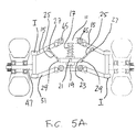
- Figures 5A-5B illustrate an embodiment of the invention applied to a four-wheel vehicle, such as a buggy. To avoid repetitions and obvious deductions on the preceding disclosure herein, only the relevant portions of this embodiment are described hereafter.
- the essential structure of the suspension system employed is that of the embodiment of figure 3.
- the vehicle comprises a chassis 11 formed by a tubular structure for supporting the load.
- the end bars 47 receive the inputs from the wheels and are articulated at joints 49 on the ends of upper and lower bars 15 and 51 which form a parallelogram structure.
- Means 53 may be provided for turning the wheel direction.
- the chassis is provided with the central frame member 11 forming part thereof and mounting the slider 19 and the common swing-arm 23 by means of the latter. Bars 25 embodying the link-arms are provided between the top bar structure 15 and the swing-arm 23.
- shock absorber means In the case of a motor-car, a similar structure may be adapted further including shock absorber means.
Landscapes
- Engineering & Computer Science (AREA)
- Mechanical Engineering (AREA)
- Axle Suspensions And Sidecars For Cycles (AREA)
Applications Claiming Priority (2)
| Application Number | Priority Date | Filing Date | Title |
|---|---|---|---|
| AR9800104 | 1998-10-05 | ||
| AR9800104 | 1998-10-05 |
Publications (1)
| Publication Number | Publication Date |
|---|---|
| EP0992374A1 true EP0992374A1 (fr) | 2000-04-12 |
Family
ID=3461064
Family Applications (1)
| Application Number | Title | Priority Date | Filing Date |
|---|---|---|---|
| EP99650093A Withdrawn EP0992374A1 (fr) | 1998-10-05 | 1999-10-04 | Système de suspension à deux entrées utilisant un dispositif ressort/amortisseur commun |
Country Status (1)
| Country | Link |
|---|---|
| EP (1) | EP0992374A1 (fr) |
Cited By (30)
| Publication number | Priority date | Publication date | Assignee | Title |
|---|---|---|---|---|
| CN108179528A (zh) * | 2018-03-05 | 2018-06-19 | 盐城融凡纺织制衣有限公司 | 一种具有减震功能的纺织机机架 |
| CN109249755A (zh) * | 2018-10-30 | 2019-01-22 | 苏昶 | 一种独立悬挂辅助伸长装置 |
| US10196106B1 (en) | 2017-07-27 | 2019-02-05 | Trvstper, Inc. | Suspension assembly for a cycle |
| CN109484115A (zh) * | 2018-10-31 | 2019-03-19 | 杭州国辰机器人科技有限公司 | 一种四轮两驱通用底盘减震悬挂系统 |
| US10300979B2 (en) | 2017-07-27 | 2019-05-28 | Trvstper, Inc. | Suspension assembly for a bicycle |
| US10308312B2 (en) | 2017-07-27 | 2019-06-04 | Trvstper, Inc. | Suspension assembly for a cycle |
| USD859125S1 (en) | 2018-02-08 | 2019-09-10 | Trvstper, Inc. | Cycle suspension rebound knob |
| USD860062S1 (en) | 2018-02-08 | 2019-09-17 | Trvstper, Inc. | Cycle suspension assembly |
| USD860061S1 (en) | 2018-02-08 | 2019-09-17 | Trvstper, Inc. | Cycle suspension assembly |
| USD861542S1 (en) | 2018-02-08 | 2019-10-01 | Trvstper, Inc. | Cycle suspension assembly |
| CN110435378A (zh) * | 2019-08-26 | 2019-11-12 | 吉林大学 | 一种特种车辆使用的油气悬架高度自动平衡机构 |
| US10518839B2 (en) | 2017-08-29 | 2019-12-31 | Trvstper, Inc. | Inline shock absorber with coil spring for a cycle wheel suspension assembly |
| US10518836B2 (en) | 2017-07-27 | 2019-12-31 | Trvstper, Inc. | Suspension assembly for a cycle |
| US10526040B2 (en) | 2017-08-28 | 2020-01-07 | Trvstper, Inc. | Inline shock absorber with gas spring for a cycle wheel suspension assembly |
| US10526039B2 (en) | 2017-07-27 | 2020-01-07 | Trvstper, Inc. | Suspension assembly for a cycle |
| US10549813B2 (en) | 2017-08-29 | 2020-02-04 | Trvstper, Inc. | Inline shock absorber with coil spring for a cycle wheel suspension assembly |
| US10549812B2 (en) | 2017-08-28 | 2020-02-04 | Trvstper, Inc. | Inline shock absorber with gas spring for a cycle wheel suspension assembly |
| USD880370S1 (en) | 2018-02-08 | 2020-04-07 | Trvstper, Inc. | Cycle suspension assembly |
| USD880372S1 (en) | 2018-02-08 | 2020-04-07 | Trvstper, Inc. | Cycle suspension assembly |
| USD880371S1 (en) | 2018-02-08 | 2020-04-07 | Trvstper, Inc. | Cycle suspension assembly |
| USD880369S1 (en) | 2018-02-08 | 2020-04-07 | Trvstper, Inc. | Cycle suspension assembly |
| US11084552B2 (en) | 2018-09-25 | 2021-08-10 | Specialized Bicycle Components, Inc. | Simplified gas spring setup for a trailing link cycle wheel suspension |
| US11208172B2 (en) | 2018-10-05 | 2021-12-28 | Specialized Bicycle Components, Inc. | Suspension pivot assemblies having a retention feature |
| US11230348B2 (en) | 2018-09-25 | 2022-01-25 | Specialized Bicycle Components, Inc. | Trailing link cycle wheel suspension assembly having gas pistons with unequal gas piston areas |
| US11230346B2 (en) | 2018-09-25 | 2022-01-25 | Specialized Bicycle Components Inc. | Cycle wheel suspension assembly having gas pistons with unequal gas piston areas |
| US11230347B2 (en) | 2018-09-25 | 2022-01-25 | Specialized Bicycle Components, Inc. | Cycle wheel suspension assembly having gas pistons with unequal gas piston areas |
| US11273887B2 (en) | 2018-10-16 | 2022-03-15 | Specialized Bicycle Components, Inc. | Cycle suspension with travel indicator |
| US11345432B2 (en) | 2018-10-12 | 2022-05-31 | Specialized Bicycle Components, Inc. | Suspension assembly for a cycle having a fork arm with dual opposing tapers |
| US11524744B2 (en) | 2019-04-09 | 2022-12-13 | Specialized Bicycle Components, Inc. | Cycle suspension with rotation sensor |
| US11945539B2 (en) | 2018-09-07 | 2024-04-02 | Specialized Bicycle Components, Inc. | Dual sided suspension assembly for a cycle wheel |
Citations (29)
| Publication number | Priority date | Publication date | Assignee | Title |
|---|---|---|---|---|
| DE611982C (de) * | 1933-07-13 | 1935-04-10 | Richard G Domnik Jun | Geteilter Fahr- oder Motorradrahmen mit gemeinsamer Lagerachse und gegenseittiger Abfederung, bei dem die beiden Rahmenteile gabelartig verkreuzt sind |
| US2128660A (en) * | 1933-11-15 | 1938-08-30 | Moorhouse Alfred | Motor vehicle |
| US2314076A (en) * | 1941-11-12 | 1943-03-16 | James E Casner | Vehicle suspension |
| FR1008870A (fr) * | 1950-01-19 | 1952-05-22 | Perfectionnements aux dispositifs de suspension pour véhicules | |
| US3089710A (en) * | 1958-02-21 | 1963-05-14 | Daimler Benz Ag | Mechanism for controlling outward inclination of a vehicle body in curves |
| US4265329A (en) | 1978-02-24 | 1981-05-05 | Cortanze Andre | Frameless motorcycle |
| US4378741A (en) | 1980-01-21 | 1983-04-05 | Si Handling Systems, Inc. | Interfaced conveyor systems and driverless vehicle for use therein |
| US4542910A (en) | 1982-01-25 | 1985-09-24 | Yamaha Hatsudoki Kabushiki Kaisha | Motorcycle suspension system |
| US4583612A (en) | 1984-07-19 | 1986-04-22 | Parker James G | Anti-pitch system for a motorcycle |
| US4627632A (en) | 1985-07-29 | 1986-12-09 | Mckagen Ollie H | Cycle suspension system |
| US4676523A (en) * | 1985-09-26 | 1987-06-30 | Rogers Ralph R | Suspension system for a trailer or the like |
| US4712638A (en) | 1985-06-25 | 1987-12-15 | Honda Giken Kogyo Kabushiki Kaisha | Suspension system for motorcycles |
| EP0258509A1 (fr) * | 1986-09-05 | 1988-03-09 | International Bicycle Corporation | Châssis de véhicule avec dispositif de suspension |
| JPH03231010A (ja) * | 1990-02-06 | 1991-10-15 | Nissan Motor Co Ltd | サスペンション装置 |
| DE4326870A1 (de) * | 1992-08-22 | 1994-03-10 | Rainer Dipl Phys Pivit | Zweirad, insbesondere Fahrrad |
| US5330219A (en) | 1993-09-13 | 1994-07-19 | Greendale Bicycle Company | Flexible and folding bicycle |
| WO1995005948A1 (fr) * | 1993-08-23 | 1995-03-02 | Orton Kevin R | Suspension performante pour automobile |
| US5417445A (en) | 1988-04-08 | 1995-05-23 | Smart; David G. | Cycles |
| WO1995025020A1 (fr) * | 1994-03-15 | 1995-09-21 | Kinetic Limited | Suspension a barres de torsion interconnectees |
| US5452910A (en) | 1994-09-09 | 1995-09-26 | Rockshox, Inc. | Rear wheel suspension for a bicycle and bicycle equipped therewith |
| US5498014A (en) | 1993-06-21 | 1996-03-12 | Kulhawik; Joseph E. | Bicycle incorporating bifurcated frame |
| GB2298693A (en) * | 1995-03-10 | 1996-09-11 | Rover Group | A linear-motion Watts linkage for a vehicle suspension |
| JPH092042A (ja) * | 1995-06-23 | 1997-01-07 | Kayaba Ind Co Ltd | アンチロール装置 |
| US5685553A (en) | 1994-09-21 | 1997-11-11 | Trek Bicycle Corp. | Suspension for a bicycle having a Y shaped frame |
| US5725227A (en) | 1995-07-20 | 1998-03-10 | Schwinn Cycling & Fitness Inc. | Suspension system for a bicycle |
| US5772227A (en) | 1994-06-06 | 1998-06-30 | Michail; George | Articulated, folding and sectional bicycle with special suspension system |
| US5785339A (en) | 1995-10-23 | 1998-07-28 | Itochu Corporation | Suspension device for a bicycle |
| US5791674A (en) | 1997-03-13 | 1998-08-11 | Cannondale Corporation | Bicycle suspension system |
| GB2332402A (en) * | 1997-12-17 | 1999-06-23 | Daimler Benz Ag | A vehicle suspension |
-
1999
- 1999-10-04 EP EP99650093A patent/EP0992374A1/fr not_active Withdrawn
Patent Citations (29)
| Publication number | Priority date | Publication date | Assignee | Title |
|---|---|---|---|---|
| DE611982C (de) * | 1933-07-13 | 1935-04-10 | Richard G Domnik Jun | Geteilter Fahr- oder Motorradrahmen mit gemeinsamer Lagerachse und gegenseittiger Abfederung, bei dem die beiden Rahmenteile gabelartig verkreuzt sind |
| US2128660A (en) * | 1933-11-15 | 1938-08-30 | Moorhouse Alfred | Motor vehicle |
| US2314076A (en) * | 1941-11-12 | 1943-03-16 | James E Casner | Vehicle suspension |
| FR1008870A (fr) * | 1950-01-19 | 1952-05-22 | Perfectionnements aux dispositifs de suspension pour véhicules | |
| US3089710A (en) * | 1958-02-21 | 1963-05-14 | Daimler Benz Ag | Mechanism for controlling outward inclination of a vehicle body in curves |
| US4265329A (en) | 1978-02-24 | 1981-05-05 | Cortanze Andre | Frameless motorcycle |
| US4378741A (en) | 1980-01-21 | 1983-04-05 | Si Handling Systems, Inc. | Interfaced conveyor systems and driverless vehicle for use therein |
| US4542910A (en) | 1982-01-25 | 1985-09-24 | Yamaha Hatsudoki Kabushiki Kaisha | Motorcycle suspension system |
| US4583612A (en) | 1984-07-19 | 1986-04-22 | Parker James G | Anti-pitch system for a motorcycle |
| US4712638A (en) | 1985-06-25 | 1987-12-15 | Honda Giken Kogyo Kabushiki Kaisha | Suspension system for motorcycles |
| US4627632A (en) | 1985-07-29 | 1986-12-09 | Mckagen Ollie H | Cycle suspension system |
| US4676523A (en) * | 1985-09-26 | 1987-06-30 | Rogers Ralph R | Suspension system for a trailer or the like |
| EP0258509A1 (fr) * | 1986-09-05 | 1988-03-09 | International Bicycle Corporation | Châssis de véhicule avec dispositif de suspension |
| US5417445A (en) | 1988-04-08 | 1995-05-23 | Smart; David G. | Cycles |
| JPH03231010A (ja) * | 1990-02-06 | 1991-10-15 | Nissan Motor Co Ltd | サスペンション装置 |
| DE4326870A1 (de) * | 1992-08-22 | 1994-03-10 | Rainer Dipl Phys Pivit | Zweirad, insbesondere Fahrrad |
| US5498014A (en) | 1993-06-21 | 1996-03-12 | Kulhawik; Joseph E. | Bicycle incorporating bifurcated frame |
| WO1995005948A1 (fr) * | 1993-08-23 | 1995-03-02 | Orton Kevin R | Suspension performante pour automobile |
| US5330219A (en) | 1993-09-13 | 1994-07-19 | Greendale Bicycle Company | Flexible and folding bicycle |
| WO1995025020A1 (fr) * | 1994-03-15 | 1995-09-21 | Kinetic Limited | Suspension a barres de torsion interconnectees |
| US5772227A (en) | 1994-06-06 | 1998-06-30 | Michail; George | Articulated, folding and sectional bicycle with special suspension system |
| US5452910A (en) | 1994-09-09 | 1995-09-26 | Rockshox, Inc. | Rear wheel suspension for a bicycle and bicycle equipped therewith |
| US5685553A (en) | 1994-09-21 | 1997-11-11 | Trek Bicycle Corp. | Suspension for a bicycle having a Y shaped frame |
| GB2298693A (en) * | 1995-03-10 | 1996-09-11 | Rover Group | A linear-motion Watts linkage for a vehicle suspension |
| JPH092042A (ja) * | 1995-06-23 | 1997-01-07 | Kayaba Ind Co Ltd | アンチロール装置 |
| US5725227A (en) | 1995-07-20 | 1998-03-10 | Schwinn Cycling & Fitness Inc. | Suspension system for a bicycle |
| US5785339A (en) | 1995-10-23 | 1998-07-28 | Itochu Corporation | Suspension device for a bicycle |
| US5791674A (en) | 1997-03-13 | 1998-08-11 | Cannondale Corporation | Bicycle suspension system |
| GB2332402A (en) * | 1997-12-17 | 1999-06-23 | Daimler Benz Ag | A vehicle suspension |
Non-Patent Citations (2)
| Title |
|---|
| PATENT ABSTRACTS OF JAPAN vol. 016, no. 007 (M - 1198) 9 January 1992 (1992-01-09) * |
| PATENT ABSTRACTS OF JAPAN vol. 1997, no. 05 30 May 1997 (1997-05-30) * |
Cited By (36)
| Publication number | Priority date | Publication date | Assignee | Title |
|---|---|---|---|---|
| US10689061B2 (en) | 2017-07-27 | 2020-06-23 | Trvstper, Inc. | Suspension assembly for a cycle |
| US10196106B1 (en) | 2017-07-27 | 2019-02-05 | Trvstper, Inc. | Suspension assembly for a cycle |
| US10300979B2 (en) | 2017-07-27 | 2019-05-28 | Trvstper, Inc. | Suspension assembly for a bicycle |
| US10308312B2 (en) | 2017-07-27 | 2019-06-04 | Trvstper, Inc. | Suspension assembly for a cycle |
| US10549815B2 (en) | 2017-07-27 | 2020-02-04 | Trvstper, Inc. | Suspension assembly for a bicycle |
| US10526039B2 (en) | 2017-07-27 | 2020-01-07 | Trvstper, Inc. | Suspension assembly for a cycle |
| US10518836B2 (en) | 2017-07-27 | 2019-12-31 | Trvstper, Inc. | Suspension assembly for a cycle |
| US10549812B2 (en) | 2017-08-28 | 2020-02-04 | Trvstper, Inc. | Inline shock absorber with gas spring for a cycle wheel suspension assembly |
| US10526040B2 (en) | 2017-08-28 | 2020-01-07 | Trvstper, Inc. | Inline shock absorber with gas spring for a cycle wheel suspension assembly |
| US10518839B2 (en) | 2017-08-29 | 2019-12-31 | Trvstper, Inc. | Inline shock absorber with coil spring for a cycle wheel suspension assembly |
| US10549813B2 (en) | 2017-08-29 | 2020-02-04 | Trvstper, Inc. | Inline shock absorber with coil spring for a cycle wheel suspension assembly |
| USD880370S1 (en) | 2018-02-08 | 2020-04-07 | Trvstper, Inc. | Cycle suspension assembly |
| USD880369S1 (en) | 2018-02-08 | 2020-04-07 | Trvstper, Inc. | Cycle suspension assembly |
| USD861542S1 (en) | 2018-02-08 | 2019-10-01 | Trvstper, Inc. | Cycle suspension assembly |
| USD860061S1 (en) | 2018-02-08 | 2019-09-17 | Trvstper, Inc. | Cycle suspension assembly |
| USD860062S1 (en) | 2018-02-08 | 2019-09-17 | Trvstper, Inc. | Cycle suspension assembly |
| USD859125S1 (en) | 2018-02-08 | 2019-09-10 | Trvstper, Inc. | Cycle suspension rebound knob |
| USD880371S1 (en) | 2018-02-08 | 2020-04-07 | Trvstper, Inc. | Cycle suspension assembly |
| USD880372S1 (en) | 2018-02-08 | 2020-04-07 | Trvstper, Inc. | Cycle suspension assembly |
| CN108179528A (zh) * | 2018-03-05 | 2018-06-19 | 盐城融凡纺织制衣有限公司 | 一种具有减震功能的纺织机机架 |
| US11945539B2 (en) | 2018-09-07 | 2024-04-02 | Specialized Bicycle Components, Inc. | Dual sided suspension assembly for a cycle wheel |
| US11230348B2 (en) | 2018-09-25 | 2022-01-25 | Specialized Bicycle Components, Inc. | Trailing link cycle wheel suspension assembly having gas pistons with unequal gas piston areas |
| US11230347B2 (en) | 2018-09-25 | 2022-01-25 | Specialized Bicycle Components, Inc. | Cycle wheel suspension assembly having gas pistons with unequal gas piston areas |
| US11084552B2 (en) | 2018-09-25 | 2021-08-10 | Specialized Bicycle Components, Inc. | Simplified gas spring setup for a trailing link cycle wheel suspension |
| US11230346B2 (en) | 2018-09-25 | 2022-01-25 | Specialized Bicycle Components Inc. | Cycle wheel suspension assembly having gas pistons with unequal gas piston areas |
| US11208172B2 (en) | 2018-10-05 | 2021-12-28 | Specialized Bicycle Components, Inc. | Suspension pivot assemblies having a retention feature |
| US11345432B2 (en) | 2018-10-12 | 2022-05-31 | Specialized Bicycle Components, Inc. | Suspension assembly for a cycle having a fork arm with dual opposing tapers |
| US11273887B2 (en) | 2018-10-16 | 2022-03-15 | Specialized Bicycle Components, Inc. | Cycle suspension with travel indicator |
| US11820457B2 (en) | 2018-10-16 | 2023-11-21 | Specialized Bicycle Components, Inc. | Cycle suspension with travel indicator |
| CN109249755A (zh) * | 2018-10-30 | 2019-01-22 | 苏昶 | 一种独立悬挂辅助伸长装置 |
| CN109249755B (zh) * | 2018-10-30 | 2023-11-14 | 苏昶 | 一种独立悬挂辅助伸长装置 |
| CN109484115B (zh) * | 2018-10-31 | 2023-11-17 | 杭州国辰机器人科技有限公司 | 一种四轮两驱通用底盘减震悬挂系统 |
| CN109484115A (zh) * | 2018-10-31 | 2019-03-19 | 杭州国辰机器人科技有限公司 | 一种四轮两驱通用底盘减震悬挂系统 |
| US11524744B2 (en) | 2019-04-09 | 2022-12-13 | Specialized Bicycle Components, Inc. | Cycle suspension with rotation sensor |
| CN110435378A (zh) * | 2019-08-26 | 2019-11-12 | 吉林大学 | 一种特种车辆使用的油气悬架高度自动平衡机构 |
| CN110435378B (zh) * | 2019-08-26 | 2024-02-09 | 吉林大学 | 一种特种车辆使用的油气悬架高度自动平衡机构 |
Similar Documents
| Publication | Publication Date | Title |
|---|---|---|
| EP0992374A1 (fr) | Système de suspension à deux entrées utilisant un dispositif ressort/amortisseur commun | |
| CA2424428C (fr) | Systeme de suspension arriere pour vehicules a deux roues, notamment des bicyclettes | |
| US5725227A (en) | Suspension system for a bicycle | |
| US6854753B2 (en) | Suspension system for a vehicle | |
| CA2083636C (fr) | Chassis de bicyclette | |
| JP3819939B2 (ja) | 自転車の懸架装置 | |
| EP1481884B1 (fr) | Suspension arrière pour bicyclette | |
| AU761847B2 (en) | Suspended front fork for mountain bike and motorcycle | |
| US5671936A (en) | Shock absorbing bicycle frame apparatus | |
| US4463964A (en) | Rear suspension system for motor vehicles | |
| US5460396A (en) | Derailleur mounting assembly for a bicycle | |
| US20040061305A1 (en) | Rear wheel suspension system for a bicycle | |
| WO2002024517A2 (fr) | Vehicule | |
| NL9401393A (nl) | Fiets bevattende een vertakt frame. | |
| US4523659A (en) | Rear suspension for a motorcycle | |
| US6286846B1 (en) | Dual input suspension system using a common spring/shock-absorber device | |
| US3964765A (en) | Bicycle | |
| WO2012063098A1 (fr) | Unité de suspension arrière pour une utilisation après fabrication dans des vélos pliables | |
| US6837506B2 (en) | Bicycle frame | |
| JP2001260973A (ja) | 一般的なばね/ショックアブソーバ装置を用いた2方向入力サスペンションシステム | |
| EP3981679A2 (fr) | Système de ressort | |
| CN220905257U (zh) | 一种中置减震的幼童拖车 | |
| GB2284395A (en) | Resilient cycle saddle mounting | |
| JPH08118930A (ja) | 前二軸車の懸架装置 | |
| CN1072893A (zh) | 弹性可折叠便携车 |
Legal Events
| Date | Code | Title | Description |
|---|---|---|---|
| PUAI | Public reference made under article 153(3) epc to a published international application that has entered the european phase |
Free format text: ORIGINAL CODE: 0009012 |
|
| AK | Designated contracting states |
Kind code of ref document: A1 Designated state(s): AT BE CH CY DE DK ES FI FR GB GR IE IT LI LU MC NL PT SE |
|
| AX | Request for extension of the european patent |
Free format text: AL;LT;LV;MK;RO;SI |
|
| 17P | Request for examination filed |
Effective date: 20001012 |
|
| AKX | Designation fees paid |
Free format text: AT BE CH CY DE DK ES FI FR GB GR IE IT LI LU MC NL PT SE |
|
| 17Q | First examination report despatched |
Effective date: 20020526 |
|
| STAA | Information on the status of an ep patent application or granted ep patent |
Free format text: STATUS: THE APPLICATION IS DEEMED TO BE WITHDRAWN |
|
| 18D | Application deemed to be withdrawn |
Effective date: 20021106 |