EP0991827B1 - Strahlungsfläche mit belüftetem hohlraum - Google Patents
Strahlungsfläche mit belüftetem hohlraum Download PDFInfo
- Publication number
- EP0991827B1 EP0991827B1 EP98931649A EP98931649A EP0991827B1 EP 0991827 B1 EP0991827 B1 EP 0991827B1 EP 98931649 A EP98931649 A EP 98931649A EP 98931649 A EP98931649 A EP 98931649A EP 0991827 B1 EP0991827 B1 EP 0991827B1
- Authority
- EP
- European Patent Office
- Prior art keywords
- barrier
- cavity
- assembly
- building
- vented cavity
- Prior art date
- Legal status (The legal status is an assumption and is not a legal conclusion. Google has not performed a legal analysis and makes no representation as to the accuracy of the status listed.)
- Expired - Lifetime
Links
- 230000004888 barrier function Effects 0.000 title claims abstract description 135
- 238000000034 method Methods 0.000 title claims description 15
- 238000009413 insulation Methods 0.000 claims description 22
- 230000000712 assembly Effects 0.000 claims description 21
- 238000000429 assembly Methods 0.000 claims description 21
- 239000000853 adhesive Substances 0.000 claims description 9
- 230000001070 adhesive effect Effects 0.000 claims description 9
- 238000002310 reflectometry Methods 0.000 claims description 3
- 230000002708 enhancing effect Effects 0.000 claims 1
- 230000001939 inductive effect Effects 0.000 claims 1
- 238000001816 cooling Methods 0.000 abstract description 7
- 239000003570 air Substances 0.000 description 20
- 239000000758 substrate Substances 0.000 description 10
- 238000009434 installation Methods 0.000 description 5
- 239000012528 membrane Substances 0.000 description 5
- 125000006850 spacer group Chemical group 0.000 description 5
- 239000000463 material Substances 0.000 description 4
- 238000005507 spraying Methods 0.000 description 4
- 239000011248 coating agent Substances 0.000 description 3
- 238000000576 coating method Methods 0.000 description 3
- 239000011810 insulating material Substances 0.000 description 3
- 230000005855 radiation Effects 0.000 description 3
- 239000004793 Polystyrene Substances 0.000 description 2
- 239000012080 ambient air Substances 0.000 description 2
- 239000000428 dust Substances 0.000 description 2
- 230000000694 effects Effects 0.000 description 2
- 239000012530 fluid Substances 0.000 description 2
- 238000010438 heat treatment Methods 0.000 description 2
- 238000004519 manufacturing process Methods 0.000 description 2
- 239000002184 metal Substances 0.000 description 2
- 238000010422 painting Methods 0.000 description 2
- 229920002223 polystyrene Polymers 0.000 description 2
- 229920002635 polyurethane Polymers 0.000 description 2
- 239000004814 polyurethane Substances 0.000 description 2
- 238000003908 quality control method Methods 0.000 description 2
- 238000009423 ventilation Methods 0.000 description 2
- 229920002799 BoPET Polymers 0.000 description 1
- 229910001335 Galvanized steel Inorganic materials 0.000 description 1
- 239000005041 Mylar™ Substances 0.000 description 1
- 230000015556 catabolic process Effects 0.000 description 1
- 238000005253 cladding Methods 0.000 description 1
- 230000003750 conditioning effect Effects 0.000 description 1
- 238000010276 construction Methods 0.000 description 1
- 230000008878 coupling Effects 0.000 description 1
- 238000010168 coupling process Methods 0.000 description 1
- 238000005859 coupling reaction Methods 0.000 description 1
- 238000006731 degradation reaction Methods 0.000 description 1
- 238000006073 displacement reaction Methods 0.000 description 1
- 230000005611 electricity Effects 0.000 description 1
- 230000007613 environmental effect Effects 0.000 description 1
- 239000003344 environmental pollutant Substances 0.000 description 1
- 239000006260 foam Substances 0.000 description 1
- 239000011888 foil Substances 0.000 description 1
- 239000008397 galvanized steel Substances 0.000 description 1
- 239000012212 insulator Substances 0.000 description 1
- ZFSLODLOARCGLH-UHFFFAOYSA-N isocyanuric acid Chemical compound OC1=NC(O)=NC(O)=N1 ZFSLODLOARCGLH-UHFFFAOYSA-N 0.000 description 1
- 238000002955 isolation Methods 0.000 description 1
- 238000010030 laminating Methods 0.000 description 1
- 230000003647 oxidation Effects 0.000 description 1
- 238000007254 oxidation reaction Methods 0.000 description 1
- 239000003973 paint Substances 0.000 description 1
- 230000000149 penetrating effect Effects 0.000 description 1
- 230000035515 penetration Effects 0.000 description 1
- 239000004033 plastic Substances 0.000 description 1
- 229920003023 plastic Polymers 0.000 description 1
- 231100000719 pollutant Toxicity 0.000 description 1
- 230000009467 reduction Effects 0.000 description 1
- 239000000565 sealant Substances 0.000 description 1
- 239000011257 shell material Substances 0.000 description 1
- 239000000126 substance Substances 0.000 description 1
Images


Classifications
-
- E—FIXED CONSTRUCTIONS
- E04—BUILDING
- E04D—ROOF COVERINGS; SKY-LIGHTS; GUTTERS; ROOF-WORKING TOOLS
- E04D13/00—Special arrangements or devices in connection with roof coverings; Protection against birds; Roof drainage; Sky-lights
- E04D13/17—Ventilation of roof coverings not otherwise provided for
-
- F—MECHANICAL ENGINEERING; LIGHTING; HEATING; WEAPONS; BLASTING
- F24—HEATING; RANGES; VENTILATING
- F24S—SOLAR HEAT COLLECTORS; SOLAR HEAT SYSTEMS
- F24S20/00—Solar heat collectors specially adapted for particular uses or environments
- F24S20/60—Solar heat collectors integrated in fixed constructions, e.g. in buildings
- F24S20/66—Solar heat collectors integrated in fixed constructions, e.g. in buildings in the form of facade constructions, e.g. wall constructions
-
- F—MECHANICAL ENGINEERING; LIGHTING; HEATING; WEAPONS; BLASTING
- F24—HEATING; RANGES; VENTILATING
- F24S—SOLAR HEAT COLLECTORS; SOLAR HEAT SYSTEMS
- F24S25/00—Arrangement of stationary mountings or supports for solar heat collector modules
- F24S25/10—Arrangement of stationary mountings or supports for solar heat collector modules extending in directions away from a supporting surface
-
- F—MECHANICAL ENGINEERING; LIGHTING; HEATING; WEAPONS; BLASTING
- F24—HEATING; RANGES; VENTILATING
- F24S—SOLAR HEAT COLLECTORS; SOLAR HEAT SYSTEMS
- F24S25/00—Arrangement of stationary mountings or supports for solar heat collector modules
- F24S25/30—Arrangement of stationary mountings or supports for solar heat collector modules using elongate rigid mounting elements extending substantially along the supporting surface, e.g. for covering buildings with solar heat collectors
- F24S25/33—Arrangement of stationary mountings or supports for solar heat collector modules using elongate rigid mounting elements extending substantially along the supporting surface, e.g. for covering buildings with solar heat collectors forming substantially planar assemblies, e.g. of coplanar or stacked profiles
-
- F—MECHANICAL ENGINEERING; LIGHTING; HEATING; WEAPONS; BLASTING
- F24—HEATING; RANGES; VENTILATING
- F24S—SOLAR HEAT COLLECTORS; SOLAR HEAT SYSTEMS
- F24S25/00—Arrangement of stationary mountings or supports for solar heat collector modules
- F24S25/40—Arrangement of stationary mountings or supports for solar heat collector modules using plate-like mounting elements, e.g. profiled or corrugated plates; Plate-like module frames
-
- F—MECHANICAL ENGINEERING; LIGHTING; HEATING; WEAPONS; BLASTING
- F24—HEATING; RANGES; VENTILATING
- F24S—SOLAR HEAT COLLECTORS; SOLAR HEAT SYSTEMS
- F24S25/00—Arrangement of stationary mountings or supports for solar heat collector modules
- F24S25/60—Fixation means, e.g. fasteners, specially adapted for supporting solar heat collector modules
- F24S25/61—Fixation means, e.g. fasteners, specially adapted for supporting solar heat collector modules for fixing to the ground or to building structures
-
- F—MECHANICAL ENGINEERING; LIGHTING; HEATING; WEAPONS; BLASTING
- F24—HEATING; RANGES; VENTILATING
- F24S—SOLAR HEAT COLLECTORS; SOLAR HEAT SYSTEMS
- F24S40/00—Safety or protection arrangements of solar heat collectors; Preventing malfunction of solar heat collectors
- F24S40/50—Preventing overheating or overpressure
- F24S40/53—Preventing overheating or overpressure by venting solar heat collector enclosures
-
- H—ELECTRICITY
- H02—GENERATION; CONVERSION OR DISTRIBUTION OF ELECTRIC POWER
- H02S—GENERATION OF ELECTRIC POWER BY CONVERSION OF INFRARED RADIATION, VISIBLE LIGHT OR ULTRAVIOLET LIGHT, e.g. USING PHOTOVOLTAIC [PV] MODULES
- H02S20/00—Supporting structures for PV modules
- H02S20/20—Supporting structures directly fixed to an immovable object
- H02S20/22—Supporting structures directly fixed to an immovable object specially adapted for buildings
- H02S20/23—Supporting structures directly fixed to an immovable object specially adapted for buildings specially adapted for roof structures
-
- F—MECHANICAL ENGINEERING; LIGHTING; HEATING; WEAPONS; BLASTING
- F24—HEATING; RANGES; VENTILATING
- F24S—SOLAR HEAT COLLECTORS; SOLAR HEAT SYSTEMS
- F24S20/00—Solar heat collectors specially adapted for particular uses or environments
- F24S20/60—Solar heat collectors integrated in fixed constructions, e.g. in buildings
- F24S20/69—Solar heat collectors integrated in fixed constructions, e.g. in buildings in the form of shingles or tiles
-
- F—MECHANICAL ENGINEERING; LIGHTING; HEATING; WEAPONS; BLASTING
- F24—HEATING; RANGES; VENTILATING
- F24S—SOLAR HEAT COLLECTORS; SOLAR HEAT SYSTEMS
- F24S25/00—Arrangement of stationary mountings or supports for solar heat collector modules
- F24S25/60—Fixation means, e.g. fasteners, specially adapted for supporting solar heat collector modules
- F24S2025/6001—Fixation means, e.g. fasteners, specially adapted for supporting solar heat collector modules by using hook and loop-type fasteners
-
- F—MECHANICAL ENGINEERING; LIGHTING; HEATING; WEAPONS; BLASTING
- F24—HEATING; RANGES; VENTILATING
- F24S—SOLAR HEAT COLLECTORS; SOLAR HEAT SYSTEMS
- F24S25/00—Arrangement of stationary mountings or supports for solar heat collector modules
- F24S25/60—Fixation means, e.g. fasteners, specially adapted for supporting solar heat collector modules
- F24S2025/6002—Fixation means, e.g. fasteners, specially adapted for supporting solar heat collector modules by using hooks
-
- F—MECHANICAL ENGINEERING; LIGHTING; HEATING; WEAPONS; BLASTING
- F24—HEATING; RANGES; VENTILATING
- F24S—SOLAR HEAT COLLECTORS; SOLAR HEAT SYSTEMS
- F24S25/00—Arrangement of stationary mountings or supports for solar heat collector modules
- F24S25/60—Fixation means, e.g. fasteners, specially adapted for supporting solar heat collector modules
- F24S2025/601—Fixation means, e.g. fasteners, specially adapted for supporting solar heat collector modules by bonding, e.g. by using adhesives
-
- Y—GENERAL TAGGING OF NEW TECHNOLOGICAL DEVELOPMENTS; GENERAL TAGGING OF CROSS-SECTIONAL TECHNOLOGIES SPANNING OVER SEVERAL SECTIONS OF THE IPC; TECHNICAL SUBJECTS COVERED BY FORMER USPC CROSS-REFERENCE ART COLLECTIONS [XRACs] AND DIGESTS
- Y02—TECHNOLOGIES OR APPLICATIONS FOR MITIGATION OR ADAPTATION AGAINST CLIMATE CHANGE
- Y02B—CLIMATE CHANGE MITIGATION TECHNOLOGIES RELATED TO BUILDINGS, e.g. HOUSING, HOUSE APPLIANCES OR RELATED END-USER APPLICATIONS
- Y02B10/00—Integration of renewable energy sources in buildings
- Y02B10/10—Photovoltaic [PV]
-
- Y—GENERAL TAGGING OF NEW TECHNOLOGICAL DEVELOPMENTS; GENERAL TAGGING OF CROSS-SECTIONAL TECHNOLOGIES SPANNING OVER SEVERAL SECTIONS OF THE IPC; TECHNICAL SUBJECTS COVERED BY FORMER USPC CROSS-REFERENCE ART COLLECTIONS [XRACs] AND DIGESTS
- Y02—TECHNOLOGIES OR APPLICATIONS FOR MITIGATION OR ADAPTATION AGAINST CLIMATE CHANGE
- Y02B—CLIMATE CHANGE MITIGATION TECHNOLOGIES RELATED TO BUILDINGS, e.g. HOUSING, HOUSE APPLIANCES OR RELATED END-USER APPLICATIONS
- Y02B10/00—Integration of renewable energy sources in buildings
- Y02B10/20—Solar thermal
-
- Y—GENERAL TAGGING OF NEW TECHNOLOGICAL DEVELOPMENTS; GENERAL TAGGING OF CROSS-SECTIONAL TECHNOLOGIES SPANNING OVER SEVERAL SECTIONS OF THE IPC; TECHNICAL SUBJECTS COVERED BY FORMER USPC CROSS-REFERENCE ART COLLECTIONS [XRACs] AND DIGESTS
- Y02—TECHNOLOGIES OR APPLICATIONS FOR MITIGATION OR ADAPTATION AGAINST CLIMATE CHANGE
- Y02E—REDUCTION OF GREENHOUSE GAS [GHG] EMISSIONS, RELATED TO ENERGY GENERATION, TRANSMISSION OR DISTRIBUTION
- Y02E10/00—Energy generation through renewable energy sources
- Y02E10/40—Solar thermal energy, e.g. solar towers
- Y02E10/44—Heat exchange systems
-
- Y—GENERAL TAGGING OF NEW TECHNOLOGICAL DEVELOPMENTS; GENERAL TAGGING OF CROSS-SECTIONAL TECHNOLOGIES SPANNING OVER SEVERAL SECTIONS OF THE IPC; TECHNICAL SUBJECTS COVERED BY FORMER USPC CROSS-REFERENCE ART COLLECTIONS [XRACs] AND DIGESTS
- Y02—TECHNOLOGIES OR APPLICATIONS FOR MITIGATION OR ADAPTATION AGAINST CLIMATE CHANGE
- Y02E—REDUCTION OF GREENHOUSE GAS [GHG] EMISSIONS, RELATED TO ENERGY GENERATION, TRANSMISSION OR DISTRIBUTION
- Y02E10/00—Energy generation through renewable energy sources
- Y02E10/40—Solar thermal energy, e.g. solar towers
- Y02E10/47—Mountings or tracking
-
- Y—GENERAL TAGGING OF NEW TECHNOLOGICAL DEVELOPMENTS; GENERAL TAGGING OF CROSS-SECTIONAL TECHNOLOGIES SPANNING OVER SEVERAL SECTIONS OF THE IPC; TECHNICAL SUBJECTS COVERED BY FORMER USPC CROSS-REFERENCE ART COLLECTIONS [XRACs] AND DIGESTS
- Y02—TECHNOLOGIES OR APPLICATIONS FOR MITIGATION OR ADAPTATION AGAINST CLIMATE CHANGE
- Y02E—REDUCTION OF GREENHOUSE GAS [GHG] EMISSIONS, RELATED TO ENERGY GENERATION, TRANSMISSION OR DISTRIBUTION
- Y02E10/00—Energy generation through renewable energy sources
- Y02E10/50—Photovoltaic [PV] energy
Definitions
- This invention generally relates to exterior building roofing/cladding assemblies, and in particular, to the inclusion of vented radiant barrier systems within such assemblies, configured to provide: radiant and convective thermal regulation of building envelopes, displacement of conventional ballast materials, extension of building shell material life, and supporting structure for photovoltaic modules.
- Thermal insulation of buildings to help keep the building interiors cool in the summer and warm in the winter, has always been a key design criterion in all but the mildest of climates.
- Conventional thermal insulation primarily involves insulating the walls and roofs to minimize conductive heat transfer.
- heat transfer by convection and radiation to and from building surfaces may also be significant.
- JP07292908 a roof with a power generating function is known of.
- the United States Patent US 5,128,181 discloses a construction element.
- the English patent extract of JP07055189 discloses an energy saving type curtain wall assembled with a solar cell.
- the present invention is directed to a vented cavity radiant barrier assembly, finding particular utility using a photovoltaic (PV) module as the barrier, which reduces the heating and cooling requirements of a building by reducing heat transfer into the building during cooling periods and reducing heat loss from the building during heating periods.
- PV photovoltaic
- the radiant barrier assembly may also help insulate the building surface from the effects of wind, rain, and other conditions.
- the invention is adaptable for use on building surfaces which are vertical, horizontal or inclined.
- the vented cavity radiant barrier assembly includes a barrier, typically a PV module, having inner and outer surfaces.
- a support assembly is secured to the barrier and extends inwardly from the inner surface of the barrier to a building surface creating a vented cavity between the building surface and the barrier inner surface.
- a low emissivity (low-e) element is associated with the inner surface; that is, one or more low-e surfaces are positioned at or between the building surface and the inner surface of the barrier.
- the support assembly is typically secured to the building surface in a manner which does not create penetrations into the building surface. This can be achieved, for example, by the use of adhesives, hook and loop fasteners or embedding the base of support assembly elements within a layer of insulation covering the roofing surface. It may also be achieved by designing the assembly to minimize wind uplift, by laterally coupling adjacent assemblies into an integrated array of assemblies, by the use of ballast-type elements and by other ways. In some situations, such as when each assembly is in the form of a shingle, fasteners which penetrate the building surface may be used.
- the low emissivity element is typically provided at the inner surface of the barrier. Doing so minimizes manufacturing difficulties, simplifies installation, reduces weathering to the low-e surface and increases quality control because the entire assembly can be made at the factory.
- the low-e element at the roofing surface eliminates the potential increase in temperature of the PV module. However, this placement also subjects the low-e surface to greater environmental degradation, such as oxidation and other chemical attacks from dust, dirt and other airborne pollutants, as well as being obscured by dust and dirt which also reduces the effectiveness of the low-e surface. Also, because the low-e element must typically be applied to the building surface in the field, there is a reduction in quality control as opposed to having the low-e element applied at the factory.
- the barrier is not a PV module but rather is a thermal insulator.
- the outer surface of the barrier is preferably a high reflectivity, high emissivity surface. This, coupled with the low emissivity surface associated with, and typically at, the inner surface of the barrier, provides for enhanced thermal performance of the system.
- the assembly is preferably made such that convective air flow through the vented cavity is enhanced by creating the cavity with at least part of the cavity exit higher than the cavity entrance. This is typically achieved automatically when assemblies are mounted to a vertical building surface, such as a wall, or an inclined building surface, such as a sloped roof. When the building surface is essentially horizontal, the barrier can be mounted to the generally horizontal building surface at an angle to the horizontal so to promote airflow through the vented cavity. In addition, or alternatively, air can be urged to pass through the vented cavity by the use of, for example, a wind vent. While a fan could also be used, it is preferred that the system be passive to help reduce energy costs, lower installations costs, and reduce system complexity.
- Wind deflectors may be used adjacent to the cavity entrance to help deflect wind into the cavity; this may be particularly useful where there is a prevailing wind from a certain direction.
- the use of wind vents, fans or wind deflectors may be important when it is necessary or desirable to mount the barrier parallel to a generally horizontal building surface.
- Another aspect of the invention is one method by which a radiant barrier assembly can be made.
- a barrier having inner and outer surfaces is selected; a low emissivity element is typically applied to the inner surface of the barrier.
- a support assembly is mounted to the barrier so that a part of the support assembly extends outwardly away from the inner surface of the barrier. This assembly can thus be mounted to the building surface in a simple and efficient manner.
- the invention is also directed to a method for mounting a vented radiant barrier assembly to a building surface.
- the barrier is secured to the building surface using the support assembly to create a vented cavity between an inner surface of the barrier and the building surface.
- at least one low-e element is located at or between the inner surface and the building surface. Often this step is carried out with the low-e element adhered to the inner surface of the barrier.
- the low-e element can also be, for example, sprayed onto the building surface or suspended as a film in the vented region between the building surface and the inner surface of the barrier.
- a roof having a black roofing surface has a solar absorptance of about .85 while a white roofing surface has a solar absorptance of about .60.
- Solar absorptance can be reduced to about .50 by covering the roofing surface with a conventional insulating paver made of 5cm-thick polystyrene covered by about 16mm of concrete.
- a horizontally-positioned radiant barrier (which could be, for example, a PV module or a rigid, weatherable panel) about 1.2 to 10cm above a flat, horizontal roofing surface reduces the solar absorptance to about .35.
- the solar absorptance is reduced to about .30 by the addition of a low-e element along the inner surface of the barrier; placing the barrier at an angle to the horizontal, preferably at least about 5°, causes the cavity entrance to be lower than the cavity exit, creates a natural ventilation air path and reduces the solar absorptance to about 0.
- the invention provides not only significant improvements in thermal performance, but also, when the barrier is a PV module, provides a source of nonpolluting electricity from the solar radiation shining on the PV module.
- Figs. 1 and 2 illustrate a number of vented cavity radiant barrier assemblies 2 mounted to various building surfaces 4, in particular a roof 6 and a wall 8 of a building 10.
- Assembly 2 includes a barrier 12, typically a PV module or a rigid, weatherable panel, mounted above building surface 4 by a support assembly 14.
- barrier 12 is a PV module, such as one sold by solarex of Frederick, Maryland as MSX 120, various electrical wires and cables will be used; these are not shown in the drawings for clarity of illustration.
- barrier 12 includes a thermal insulation component, it preferably has an insulation value of at least about R2 and preferably about R5 to R15. Suitable materials for the insulation component include polystyrene, polyurethane and isocyanurate.
- the thermal insulating valve of the barrier typically ranges from about R5 to over R20 depending on the type of insulating material used and its thickness.
- support assembly 14 includes four supports 16 secured to and extending downwardly away from the inside surface 18 of barrier 12. Supports 16 are also secured to building surface 4, typically without penetrating building surface 4 as described in more detail below.
- Assembly 2 further includes a low emissivity element 20 at inner surface 18.
- Low-e elements are shown by dashed lines in the figures for ease of illustration.
- Low-e element 20 is preferably an integral part of barrier 12 at inner surface 18 and can take a variety of forms.
- Low-e element 20 may include metal foil or metalized plastic such as Mylar ® , low-e spray coatings and may be applied to barrier 12 by laminating or painting or spraying.
- Emissivity is defined as the ratio of total radiating power of a real surface to that of a black body surface.
- Low-e means having an emissivity typically below .4, and preferably below .08.
- Low emissivity is generally a characteristic of shiny metal surfaces.
- Barrier 12 also includes an outer surface 22. Outer surface 22 may be the solar receiving surface when barrier 12 is a PV module. When barrier 12 is a rigid panel, outer surface 22 may be a high reflectivity, high emissivity surface, such as a white painted surface, for enhanced thermal conditioning of
- Assembly 2 defines a vented cavity 24 between building surface 4 and inner surface 18 of barrier 12.
- the provision of vented cavity 24 permits free air flow, and thus the flow of cooling air currents as indicated by arrows 26, between barrier 12 and building surface 4.
- Vented cavity 24 is preferably about 1.2cm to 10cm (1/2 to 4 inches) high and more preferably is about 4.8cm (1.9 inches) high.
- vented cavity 24 has a generally uniform height between a cavity entrance 28 and a cavity exit 30.
- the cavity exit 30 is higher than the cavity entrance 28 to help induce cooling air flow through vented cavity 24. This is achieved naturally when assemblies 2 are mounted to vertical walls 8 or inclined roofs 6 as in Fig.
- Fig. 2A illustrates an alternative embodiment of the invention with like elements referred to with like reference numerals.
- Radiant barrier assembly 2A is shown to include a barrier 12 supported above building surface 4 by segmented supports 16A.
- Low-e elements 20, 20A and 20B are used at and between inner surface 18 of barrier 12 and building surface 4.
- low-e element 20A is suspended within vented cavity 24 between segmented supports 16A to in effect produce two vented cavities.
- An example of low-e element 20A is a sheet of galvanized steel, approximately 24 gauge.
- Low-e element 20A can include a low-e surface facing either or both of surfaces 18, 4.
- Low-e element 20B is typically made by spraying or painting metalized paint on top of building surface 4 prior to installation of assembly 2A.
- low-e element 20B A suitable material for low-e element 20B is sold by Solar Energy Corporation of Princeton, New Jersey as LO/MIT-I. As discussed above in the summary, there are advantages and disadvantages relating to the use of low-e elements at inner surface 18, at building surface 4 and between the two surfaces. Based on the particular circumstances, one, two or all three of low-e elements of 20, 20A and 20B may be used with a vented cavity radiant barrier assembly.
- Fig. 3 illustrates a vented cavity radiant barrier assembly 2B in which supports 16B are in the form of I-shaped supports which support the edges of adjacent barriers 12 over building surface 4.
- Building surface 4 is shown to include a building surface substrate 32 over which a weather-proof membrane 34 is used.
- low-e element 20B is used at membrane 34
- a low-e element 20 is used at lower surface 18.
- Supports 16B are secured to inner surface 18 through the use of clips 36 while the lower portion of supports 16B are secured to membrane 34 of building surface 4 through the use of an appropriate adhesive 38. Hook and loop fasteners or other appropriate fastening elements could also be used to secure supports 16B to barrier 12 and to surface 4.
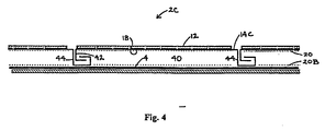
- Fig. 4 shows a further embodiment of the invention in which assembly 2C is shown with a different type of support assembly 14C.
- Support assembly 14C includes a pan or body 40, supporting barrier 12, and interlocking legs 42, 44 along the lateral edges of body 40.
- Body 40 in essence forms the inner surface 18 of barrier 12 with low-e element 20 at inner surface 18.
- Low-e element 20B is applied to building surface 4 as with the embodiment of Fig. 3 .
- Legs 44 are secured to surface 4 using fasteners such as adhesives, hook and loop fasteners, clips, etc.
- Legs 42 are secured to legs 44 both by their mechanical interlocking illustrated in Fig. 4 , and, if appropriate, with the use of an adhesive or sealant between the interlocking portions of the legs. Note that the gaps between legs 42, 44 are exaggerated in Fig. 4 for purposes of illustration.
- Fig. 4A illustrates an alternative to the radiant barrier assembly 2C of Fig. 4 .
- Assembly 2D uses a clip or connector 46 to engage the legs 42, 44 and secure the legs to surface 4. This permits connector 46 to be mounted to surface 4 prior to positioning barrier 12, with pan 40 and legs 42, 44 extending therefrom, onto building surface 4.
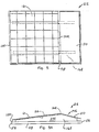
- Support assembly 14E includes a pair of angled spacers 16E supporting barrier 12 on an incline of at least about 5°, and preferably about 10° to 20° to the horizontal. Spacers 16E are supported by a thermal insulation panel 48. Panel 48 has a projection 52 extending into a recess 54 formed in an adjacent panel 48 to permit interlocking of adjacent assemblies 2E. Vented cavity 24E is open to the atmosphere through the cavity entrance 28E, formed at the lower end of barrier 12, and through a cavity exit 30E.
- Cavity exit 30E is formed as a gap between the upper end of barrier 12 and a reverse angle deflector panel 50, panel 50 also being supported by spacers 16E.
- barrier 12 is inclined for enhanced solar radiation reception at appropriate latitudes and climates and is inclined to cause the cavity entrance to be lower than the cavity exit for enhanced air flow and thus cooling of vented cavity 24E.
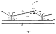
- FIG. 6 illustrates a further embodiment of the invention in which assembly 2F has some of the attributes of the embodiments of Figs. 4 and 5 .
- Support assembly 14F is seen to include a pan 40F supporting barrier 12 at an angle to the horizontal.
- Pan 40F includes a reverse angle portion 56 which is perforated for air ventilation. Air can enter vented cavity 24F through a cavity entrance 28F, formed by holes formed in pan 40F adjacent to the low end of barrier 12; air flows upwardly through cavity 24F and through cavity exit 30F formed adjacent to the upper end of barrier 12 by the holes in reverse angle portion 56.
- Support assembly 14F includes a hold down 62 having a base 64 lying adjacent to membrane or coating 34, coating 34 covering a continuous insulation layer 68.
- Hold down 62 also includes a vertical extension portion 66 extending upwardly away from base 64.
- Support assembly 14F also includes standoffs or legs 58 extending downwardly from pan 40F; legs 58 have bases 60 which rest on base 64. Extension 66 extends upwardly between legs 58 and terminates in deflectable clips or wings 70 at the outer ends of portion 66.
- the combination of barrier 12 supported by pan 40F with legs 58 extending from the lateral edges of the pan can be snapped into place between pairs of hold downs 62. During this final installation step, clips or wings 70 pivot downwardly then snap back to the orientation of Fig. 6 to engage and secure the lateral edges of pan 40F in place.
- hold downs 62 are indirectly secured to building surface substrate 32 using an adhesive to fasten base 64 to coating 34. It may be desirable to make extension 66 longer and have base 64 be secured directly to building surface substrate 32, preferably with non-surface-penetrating elements such as an adhesive, or with surface-penetrating fasteners such as roofing nails, at appropriate positions.
- Continuous insulation layer 68 is then applied, typically by spraying foam, such as polyurethane, onto building surface substrate 32.
- Weatherproof membrane 34 is then applied to continuous insulation layer 68 to provide the desired weatherproofing for the building.
- Insulation layer 68 and insulation panel 48 each preferably has an insulation value of at least about R3 per inch (R1.2 per cm). Layer 68 and panel 48 are each typically about 2.5 to 7.5cm (1 to 3 inches) thick.
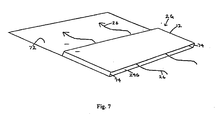
- Fig. 7 illustrates the radiant barrier assembly 2G made in the form of a shingle.
- Radiant barrier assembly 2G includes a barrier 12 secured to a base 72 by two or more parallel edge spacers 74. As illustrated by arrows 26, air flow between barrier 12 and base 72 provides cooling to vented cavity 24G.
- Base 72 has a larger surface area than panel 12, preferably at least about 20% larger, to permit assemblies 2G to be mounted as shingles.
- Fig. 8 illustrates a second shingle-type embodiment of the invention in which radiant barrier assemblies 2H are mounted to abut one another but with the lower ends of vented cavities 24H, defining cavity entrances 28H, being farther from base 72 than the upper ends of vented cavity 24H, that is cavity exits 30H. While the lower-most radiant barrier assembly 2H can have air flow in through its entire cavity entrance 28H, the other barrier assemblies 2H receive ambient air through only the upper-most of their cavity entrances 28H as indicated by arrows 76.
- a hot air collector 78 can be mounted adjacent to the cavity exit 30H of the upper-most assembly 2H to permit the heated air to be, for example, exhausted to the ambient atmosphere or to be directed directly into the interior of building 10, or to be directed to a heat exchanger.
- Low-e element 20 can be used at the inner surface of barriers 12 in both the embodiments of Figs. 7 and 8 but are not shown in the drawings for clarity. If a low-e element 2B were to be used, it would be applied to the upper surface of base 72 beneath barrier 12. As a shingle element, assemblies 2G and 2H are typically mounted to building surface 4 by the use of roofing nails, not shown.
- Fig. 9 illustrates a further embodiment of the invention in which assembly 2I includes a barrier 12 and a support assembly 14H in the form of a fluid-permeable substrate.
- Fluid-permeable substrate 14H can take the form of, for example, horizontally oriented tubes or an air-porous strip, preferably on the order of about 12.5cm (5 inches) wide by about 1.25cm (0.5 inch) thick.
- the location of low-e element 20 with the embodiment of Fig. 9 may be at inner surface 18 of barrier 12 or at building surface 4, or both, depending primarily on the type of material used as the fluid-permeable substrate. When used with a flat roof, it is desired to use something which would help draw ambient air between barrier 12 and building surface 4, that is through fluid permeable substrate 14H.
- the embodiment of Fig. 9 illustrates use of a conventional, passively-driven wind vent 80. Instead of a wind vent, a fan or other type of air pump could be used as well, and the heat can be drawn off for use by the building.
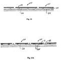
- Figs. 10A and 10B illustrate two further embodiments of the invention in which radiant barrier assemblies 2J and 2K are shown mounted to a standing seam or other corrugation type of roofing system.
- the roofing system includes standing seams 82 separated by generally flat panels or pans 84.
- barrier 12 is mounted to and spans a pair of standing seams 82 so that the standing seams lie below and possibly support the support assembly.
- separate supports 16K are used to support barrier 12 between pairs of standing seams 82.
- One preferred method for manufacturing of radiant barrier assembly 2 includes the steps of selecting a barrier, preferably a PV module having inner and outer surfaces 18, 22, and adhering a low-e element 20 to the inner surface.
- a support assembly 14 is then mounted to barrier 12 to create the assembly 2.
- This assembly can then be installed in the field directly to building surface 2.
- One or more additional low-e elements 20A, 20B can be used in the installation of the system.
- the support assembly can be secured to the building surface in a variety of ways, including the use of adhesives, clips, hook and loop fasteners, and other appropriate methods.
- support assembly 14 can be designed to include a portion of the support assembly embedded within the continuous insulation layer and extending out and up through the outer surface of the insulation layer so that the insulation layer itself helps to secure the radiant barrier assembly to the building.
- inner surface 18 of barrier 12 will not include low-e element 20; in those situations low-e elements 20A and/or 20B may be used spaced apart from surface 18 to create the desired thermal isolation of building 10.
- the assembly may further comprise a hold down element (62) with a base secured to the support assembly, the base having a base outer surface being positioned in such a way that said vented cavity is created between the barrier inner surface and the base outer surface.
- a hold down element (62) with a base secured to the support assembly, the base having a base outer surface being positioned in such a way that said vented cavity is created between the barrier inner surface and the base outer surface.
- the base may comprise a layer of a thermal insulating material, and the part of the support assembly may be embedded within the thermal insulating material.
- the barrier may comprise a photovoltaic module and the base may be substantially larger than the barrier so said assembly is in the form of a shingle to permit said assembly to be fastened to the building surface.
Claims (21)
- Strahlungsbarrierenanordnung (2, 2A-K) mit belüftetem Hohlraum, die an einer Gebäudefläche (4) angebracht werden kann, wobei sie umfasst:eine Barriere (12), die als eine Platte mit einer Innen- und einer Außenfläche (18; 22) ausgeführt ist,eine Trageanordnung (14,14E, 14F, 14H), die an der Barriere (12) befestigt ist und sich relativ zu der Innenfläche (18) nach innen erstreckt, wobei die Trageanordnung (16) einen Teil aufweist, der von der Innenfläche (18) beabstandet ist und an einer Gebäudefläche befestigt werden kann, um einen belüfteten Hohlraum (24, 24E-24H) auszubilden, der zwischen der Gebäudefläche (4) und der Innenfläche (18) zu schaffen ist, und Luftstrom durch den Hohlraum (24, 24E-H) zu bewirken, undein Element niedriger Emissivität (low emissivity element) (20, 20A, 20B), das sich an der Innenfläche (18) befindet und/oder innerhalb des auszubildenden belüfteten Hohlraums zwischen segmentierten Trägern (16) der Trageanordnung (14, 14E, 14F, 14H) aufgehängt ist.
- Strahlungsbarrierenanordnung (2, 2A, 2K) mit belüftetem Hohlraum, wobei die Anordnung (2, 2A, 2K) an einer Gebäudefläche (4) angebracht ist und umfasst:eine Barriere (12), die als eine Platte mit einer Innen- und einer Außenfläche (18; 22) ausgeführt ist,eine Trageanordnung (14, 14E, 14F, 14H), die an der Barriere (12) befestigt ist und sich relativ zu der Innenfläche (18) nach innen erstreckt,
wobei die Trageanordnung (14, 14E, 14F, 14H) einen Teil aufweist, der von der Innenfläche (18) beabstandet ist und an der Gebäudefläche (22) befestigt ist, um einen belüfteten Hohlraum (24, 24E-H) auszubilden, der zwischen der Gebäudefläche (4) und der Innenfläche (18) geschaffen wird, und Luftstrom zu dem Hohlraum (24, 24E-H) zu bewirken, und
ein Element niedriger Emissivität (20, 20A, 20B), das sich an der Innenfläche (18) der Gebäudefläche (4) oder/und zwischen der Innen- und der Gebäudefläche (14, 18) und im Abstand dazu befindet. - Anordnung nach Anspruch 1 oder 2, wobei:die Barriere (12) wenigstens ein Photovoltaikmodul an der Sonnenstrahlung aufnehmenden Außenfläche (22) der Barriere (12) und eine Wärmedämmplatte umfasst;die Trageanordnung (14, 14E, 14F, 14H) an der Innenfläche (18) befestigt ist.
- Anordnung nach Anspruch 1 oder 2, wobei die Außenfläche eine stark reflektierende, stark emittierende Fläche ist und der Teil der Trageanordnung (14, 14E, 14F, 14H) wenigstens umfasst:eine Klebstoff-Auftragfläche, auf die ein Klebstoff (38) aufgetragen werden kann, um Ankleben des Teils an einer Gebäudefläche (4) zu ermöglichen;ein Klettverbindungselement; oder/undein Klemmelement (46).
- Anordnung nach Anspruch 1 oder 2, wobei die Außenfläche der Barriere (12) einen Photovoltaikmodul-Abschnitt in einer ersten Winkelausrichtung sowie einen Umkehrwinkel-Abschnitt (56) in einer zweiten Winkelausrichtung umfasst.
- Anordnung nach Anspruch 1 oder 2, wobei die Trageanordnung (14, 14E, 14F, 14H) wenigstens eines der folgenden Elemente umfasst:Kopplungselemente, die zulassen, dass benachbarte der Anordnungen gekoppelt werden;eine fluiddurchlässige Schicht (14H), die mit der Innenfläche in Kontakt ist und den belüfteten Hohlraum wenigstens im Wesentlichen ausfüllt;eine Vielzahl von Wärmedämmblöcken;eine Vielzahl von Abstandshaltern und dazugehörigen Halteelementen; undeinen ersten und einen zweiten parallelen Kopplungsschenkel, so dass der erste Schenkel der einen Strahlungsbarrierenanordnung mit dem zweiten Schenkel einer benachbarten Strahlungsbarrierenanordnung gekoppelt werden kann;eine Dachplatte mit Stegfalz; und,eine gewellte Dachplatte.
- Anordnung nach Anspruch 1 oder 2, wobei das Element niedriger Emissivität (20, 20A, 20B) eine Emissivität von nicht mehr als ungefähr 0,4 hat.
- Anordnung nach Anspruch 1 oder 2, wobei die Außenfläche (22) im Allgemeinen parallel zu der Gebäudefläche ist.
- Anordnung nach Anspruch 1 oder 2, die des Weiteren eine Einrichtung zum Bewirken von Luftstrom durch den belüfteten Hohlraum hindurch umfasst.
- Anordnung nach Anspruch 1 oder 2, wobei:die Strahlungsbarrierenanordnung mit belüftetem Hohlraum an einer geneigten Gebäudefläche (4) angebracht werden kann;der belüftete Hohlraum einen Hohlraum-Eingang (28, 28E-H) und einen Hohlraum-Ausgang (30, 30E-H) hat und wenigstens ein Teil des Hohlraum-Ausgangs (30, 30E-H) höher liegt als der Hohlraum-Eingang (28, 28E-H), um Luftstrom durch den belüfteten Hohlraum (24, 24E-H) zu begünstigen.
- Anordnung nach Anspruch 1 oder 2, die des Weiteren eine Luftstrom-Erzeugungseinrichtung (80) umfasst, die in Fluidverbindung mit dem belüfteten Hohlraum (24, 24E-H) steht, um Luft durch den belüfteten Hohlraum hindurch zu drängen.
- Verfahren zum Herstellen einer Strahlungsbarrierenanordnung (2, 2A-K) mit belüftetem Hohlraum, das die folgenden Schritte umfasst:Auswählen einer Barriere (12) mit einer Innen- und einer Außenfläche (18; 22);Anordnen eines Elementes niedriger Emissivität (20, 20A, 20B) wenigstens an der Innenfläche (18), einer Gebäudefläche (24) eines Gebäudes (10) oder/und zwischen der Innen- und der Gebäudefläche (14, 18) und im Abstand dazu;Anbringen einer Trageanordnung (14, 14E, 14F, 14H) an der Barriere (12), so dass sich ein Teil der Trageanordnung (14, 14E, 14F, 14H) von der Innenfläche (18) weg nach außen erstreckt; undBefestigen der Barriere (12) an einer Gebäudefläche (4) unter Verwendung einer Trageanordnung (14, 14E, 14F, 14H), um so einen belüfteten Hohlraum (24, 24E-H) zwischen der Innenfläche (18) und der Gebäudefläche (4) auszubilden.
- Verfahren nach Anspruch 12, wobei der Schritt des Auswählens der Barriere (12) ausgeführt wird, indem ein Photovoltaikmodul als die Barriere (12) ausgewählt wird.
- Verfahren nach Anspruch 12, wobei es den Schritt des Anbringens des Elementes niedriger Emissivität (20, 20A, 20B) an der Innenfläche (18) umfasst.
- Verfahren nach Anspruch 12, wobei der Befestigungsschritt an einer geneigten Gebäudefläche (4) ausgeführt wird.
- Verfahren nach Anspruch 12, wobei der Befestigungsschritt den Schritt des Einbettens unterer Enden von Trageanordnungs-Elementen in einer Wärmedämmschicht an der Gebäudefläche (4) umfasst.
- Verfahren nach Anspruch 12, das des Weiteren den Schritt des Auswählens eines Photovoltaikmoduls (PV) als die Barriere (12) umfasst.
- Verfahren nach Anspruch 17, das des Weiteren den Schritt des Auswählens einer Trageanordnung umfasst, die eine Basis enthält, die an einer geneigten Gebäudefläche (4) angebracht werden kann, wobei die Basis eine Basisfläche hat, die wenigstens 20 % größer ist als das Photovoltaikmodul.
- Verfahren nach Anspruch 17, das des Weiteren den Schritt des Anbringens einer Vielzahl der Barriereanordnungen (2, 2A-2K) umfasst, wobei sich die Basen schindelartig überlappen.
- Verfahren nach Anspruch 12, das des Weiteren den Schritt des seitlichen Koppelns benachbarter der Barriereanordnungen beim Anbringen an der Gebäudefläche (4) umfasst.
- Verfahren nach Anspruch 12, wobei der Schritt des Befestigens den Schritt des Verstärkens eines konvektiven Luftstroms durch den belüfteten Hohlraum (24, 24E-H) durch Erschaffen eines Hohlraum-Eingangs (28, 28E-H) und eines Hohlraum-Ausgangs (30, 30E-H) zu/von dem belüfteten Hohlraum sowie des Anordnens wenigstens eines Teils des Hohlraum-Ausgangs höher als der Hohlraum-Eingang umfasst.
Applications Claiming Priority (9)
| Application Number | Priority Date | Filing Date | Title |
|---|---|---|---|
| US5076997P | 1997-06-25 | 1997-06-25 | |
| US50769P | 1997-06-25 | ||
| US7289498P | 1998-01-28 | 1998-01-28 | |
| US72894P | 1998-01-28 | ||
| US09/019,427 US6148570A (en) | 1998-02-05 | 1998-02-05 | Photovoltaic building assembly with continuous insulation layer |
| US19427 | 1998-02-05 | ||
| US104027 | 1998-06-24 | ||
| US09/104,027 US6061978A (en) | 1997-06-25 | 1998-06-24 | Vented cavity radiant barrier assembly and method |
| PCT/US1998/013352 WO1998059122A2 (en) | 1997-06-25 | 1998-06-25 | Vented cavity radiant barrier assembly and method |
Publications (3)
| Publication Number | Publication Date |
|---|---|
| EP0991827A2 EP0991827A2 (de) | 2000-04-12 |
| EP0991827A4 EP0991827A4 (de) | 2005-10-26 |
| EP0991827B1 true EP0991827B1 (de) | 2011-03-09 |
Family
ID=27486847
Family Applications (1)
| Application Number | Title | Priority Date | Filing Date |
|---|---|---|---|
| EP98931649A Expired - Lifetime EP0991827B1 (de) | 1997-06-25 | 1998-06-25 | Strahlungsfläche mit belüftetem hohlraum |
Country Status (6)
| Country | Link |
|---|---|
| US (1) | US6061978A (de) |
| EP (1) | EP0991827B1 (de) |
| JP (1) | JP2002514279A (de) |
| CN (1) | CN1125221C (de) |
| AU (1) | AU735829B2 (de) |
| WO (1) | WO1998059122A2 (de) |
Cited By (3)
| Publication number | Priority date | Publication date | Assignee | Title |
|---|---|---|---|---|
| US8307606B1 (en) | 2011-07-07 | 2012-11-13 | Solon Corporation | Integrated photovoltaic rooftop modules |
| US9263985B2 (en) | 2012-11-13 | 2016-02-16 | Pi Solar Technology Gmbh | Rooftop photovoltaic modules |
| US9628019B1 (en) | 2016-09-09 | 2017-04-18 | Polar Racking Inc. | Photovoltaic panel racking system |
Families Citing this family (157)
| Publication number | Priority date | Publication date | Assignee | Title |
|---|---|---|---|---|
| US5746839A (en) * | 1996-04-08 | 1998-05-05 | Powerlight Corporation | Lightweight, self-ballasting photovoltaic roofing assembly |
| US6601348B2 (en) * | 2000-08-10 | 2003-08-05 | University Of Colorado Research Foundation | Structures for mitigating wind suction atop a flat or slightly inclined roof |
| EP1313926A1 (de) * | 2000-08-24 | 2003-05-28 | Powerlight Corporation | Photovoltaikkonstrktion mit durchgehender isolationsschicht |
| US6534703B2 (en) | 2001-07-10 | 2003-03-18 | Powerlight Corporation | Multi-position photovoltaic assembly |
| US6570084B2 (en) * | 2001-07-10 | 2003-05-27 | Powerlight Corporation | Pressure equalizing photovoltaic assembly and method |
| US6495750B1 (en) | 2001-07-10 | 2002-12-17 | Powerlight Corporation | Stabilized PV system |
| US6501013B1 (en) | 2001-07-10 | 2002-12-31 | Powerlight Corporation | Photovoltaic assembly array with covered bases |
| EP1306907A1 (de) * | 2001-10-29 | 2003-05-02 | BP Solar Espana, S.A. | Einbausystem mit geringem Ballast |
| US6617507B2 (en) | 2001-11-16 | 2003-09-09 | First Solar, Llc | Photovoltaic array |
| US7143557B1 (en) | 2002-01-04 | 2006-12-05 | Ayers Jr W Howard | Structural vent assembly for a roof perimeter |
| US20030154667A1 (en) * | 2002-02-20 | 2003-08-21 | Dinwoodie Thomas L. | Shingle system |
| US6883290B2 (en) | 2002-02-20 | 2005-04-26 | Powerlight Corporation | Shingle system and method |
| US7178295B2 (en) | 2002-02-20 | 2007-02-20 | Powerlight Corporation | Shingle assembly |
| US6606823B1 (en) | 2002-03-20 | 2003-08-19 | Ford Motor Land Development Corporation | Modular roof covering system |
| US7143558B2 (en) * | 2003-01-22 | 2006-12-05 | Robert Michael Trotter | Drying system for structural waterproofing |
| US20050072456A1 (en) * | 2003-01-23 | 2005-04-07 | Stevenson Edward J. | Integrated photovoltaic roofing system |
| US7342171B2 (en) * | 2003-01-23 | 2008-03-11 | Solar Intergrated Technologies, Inc. | Integrated photovoltaic roofing component and panel |
| US6959517B2 (en) * | 2003-05-09 | 2005-11-01 | First Solar, Llc | Photovoltaic panel mounting bracket |
| US6750392B1 (en) * | 2003-06-06 | 2004-06-15 | Kuo-Yow Yen | Photovoltaic cooling system |
| KR100849304B1 (ko) | 2003-08-20 | 2008-07-29 | 선파워 코포레이션 시스템즈 | Pv 모듈 어레이의 pv 모듈들 또는 pv 조립체 어레이의 pv 조립체들의 상부면과 하부면 사이의 압력 균일화를 향상하는 방법 및 pv 설비 |
| US20070180785A1 (en) * | 2003-09-18 | 2007-08-09 | Trotter Robert M | Method and device for creating a drainage conduit |
| US20050166955A1 (en) * | 2004-01-29 | 2005-08-04 | Prem Nath | Support system for photovoltaic device and method for its use |
| US7592537B1 (en) | 2004-02-05 | 2009-09-22 | John Raymond West | Method and apparatus for mounting photovoltaic modules |
| US7297866B2 (en) * | 2004-03-15 | 2007-11-20 | Sunpower Corporation | Ventilated photovoltaic module frame |
| US7905227B2 (en) * | 2004-03-30 | 2011-03-15 | Energy Innovations, Inc. | Self-ballasting solar collector |
| US7823583B2 (en) * | 2004-03-30 | 2010-11-02 | Energy Innovations, Inc. | Solar collector mounting array |
| US7156088B2 (en) * | 2004-03-30 | 2007-01-02 | Energy Innovations, Inc. | Solar collector mounting array |
| US7406800B2 (en) * | 2004-05-18 | 2008-08-05 | Andalay Solar, Inc. | Mounting system for a solar panel |
| US7155870B2 (en) * | 2004-06-18 | 2007-01-02 | Powerlight Corp. | Shingle assembly with support bracket |
| US8276329B2 (en) | 2005-05-27 | 2012-10-02 | Sunpower Corporation | Fire resistant PV shingle assembly |
| JP4932179B2 (ja) * | 2004-07-02 | 2012-05-16 | 新日本製鐵株式会社 | 外壁構造、屋根構造 |
| US20060052051A1 (en) * | 2004-09-02 | 2006-03-09 | Daniels William B Ii | Roof providing improved passive ventilation and energy efficiency |
| US7219476B2 (en) * | 2004-11-30 | 2007-05-22 | Akins Faron L | Roofing system |
| US7818922B2 (en) * | 2005-04-01 | 2010-10-26 | Billy Ellis | Thermal insulation for a building |
| US20060266352A1 (en) * | 2005-05-31 | 2006-11-30 | Finley Shapiro Consulting, Inc. | Self-ballasting solar array mount |
| WO2007038170A1 (en) | 2005-09-23 | 2007-04-05 | Daniels William B | Passive ventilation control system |
| US20070130850A1 (en) * | 2005-12-03 | 2007-06-14 | Sierra Madre Marketing Group | Ventilated roofing tiles |
| EP1969640B1 (de) * | 2005-12-28 | 2017-08-23 | SunPower Corporation, Systems | Unterstützte PV-Modulbaugruppe |
| WO2007076519A2 (en) * | 2005-12-29 | 2007-07-05 | Sunpower Corporation, Systems | One piece, collapsible pv assembly |
| DE102006009412A1 (de) * | 2006-02-23 | 2007-08-30 | Zentrum für Sonnenenergie- und Wasserstoff-Forschung Baden-Württemberg | Solarmodulsystem mit Tragstruktur |
| US7618310B2 (en) * | 2006-03-06 | 2009-11-17 | Daniels Gregory S | Apparatus and methods for ventilation of solar roof panels |
| US20070243820A1 (en) | 2006-04-18 | 2007-10-18 | O'hagin Carolina | Automatic roof ventilation system |
| EP2022099A2 (de) * | 2006-04-21 | 2009-02-11 | SunPower Corporation, Systems | Sonnenkollektorenanordnung mit reflektierender oberfläche |
| US20090266400A1 (en) * | 2006-04-22 | 2009-10-29 | Deliddo Jack P | Apparatus and method for attaching solar panels to roof system surfaces |
| WO2007123927A2 (en) * | 2007-04-17 | 2007-11-01 | Deliddo Jack P | Apparatus and method for attaching solar panels to roof system surfaces |
| DE102006022455A1 (de) * | 2006-05-13 | 2007-11-22 | Henkel Kgaa | Vorrichtung zur Befestigung eines Anbauteils |
| GB0610525D0 (en) * | 2006-05-26 | 2006-07-05 | Solar Century Holdings Ltd | Flexible solar collector roof system |
| US8122666B2 (en) * | 2006-08-10 | 2012-02-28 | Vivek Gupta | Insulating and heat dissipating panels |
| DE202006016382U1 (de) * | 2006-10-20 | 2007-02-15 | Hoeft, Duhay, Kempkensteffen GbR (vertretungsberechtigter Gesellschafter: Herr Klaus-Dieter Hoeft, 33332 Gütersloh) | Flachdachaufsatz mit Solarmodulen |
| JP5303108B2 (ja) * | 2006-09-29 | 2013-10-02 | 京セラ株式会社 | 太陽光発電装置、及びそれを具備する建物 |
| US7610729B1 (en) | 2006-11-16 | 2009-11-03 | Ayers Jr W Howard | Structural vent assembly for a roof perimeter |
| CN101584049B (zh) * | 2006-11-21 | 2014-08-13 | 凡世通建筑产品公司 | 将太阳能板安装到屋顶膜的粘扣装置 |
| JP2010534820A (ja) * | 2007-07-24 | 2010-11-11 | サンパワー コーポレイション | ローリング式追跡ソーラーアセンブリ |
| US7735267B1 (en) | 2007-08-01 | 2010-06-15 | Ayers Jr W Howard | Structural vented roof deck enclosure system |
| US8505248B1 (en) | 2007-09-21 | 2013-08-13 | Andalay Solar, Inc. | Minimal ballasted surface mounting system and method |
| US8813460B2 (en) * | 2007-09-21 | 2014-08-26 | Andalay Solar, Inc. | Mounting system for solar panels |
| US8938919B2 (en) * | 2007-09-21 | 2015-01-27 | Andalay Solar, Inc. | Electrical connectors for solar modules |
| WO2009061956A1 (en) * | 2007-11-06 | 2009-05-14 | Ming-Liang Shiao | Photovoltaic roofing elements and roofs using them |
| US8707643B1 (en) | 2007-11-08 | 2014-04-29 | Certainteed Corporation | Roofing element and roof covering comprised thereof |
| US20100330898A1 (en) * | 2008-02-26 | 2010-12-30 | Daniels Gregory S | Roof ventilation system |
| US8832938B2 (en) * | 2008-03-27 | 2014-09-16 | Panelclaw, Inc. | Ground mounted solar module integration system |
| US8748733B2 (en) * | 2008-03-27 | 2014-06-10 | Panelclaw, Inc. | Solar module integration system |
| US8297008B2 (en) * | 2008-04-02 | 2012-10-30 | Adco Products, Inc. | System and method for attaching a solar module to a substrate |
| RU2526290C2 (ru) | 2008-05-13 | 2014-08-20 | Грегори С. ДЭНИЭЛС | Крышная вентиляционная система, устойчивая к воздействию тлеющих углей и огня |
| CN201285767Y (zh) * | 2008-10-13 | 2009-08-05 | 杨锦怀 | 一种光电模块 |
| US7956281B2 (en) * | 2008-11-12 | 2011-06-07 | Sunpower Corporation | Flexible wind deflector for photovoltaic array perimeter assembly |
| CN101736818B (zh) * | 2008-11-19 | 2012-08-15 | 冯刚克 | 新型通风空调生态型建筑及其施工方法 |
| US9103563B1 (en) | 2008-12-30 | 2015-08-11 | Sunedison, Inc. | Integrated thermal module and back plate structure and related methods |
| US8739478B1 (en) | 2008-12-30 | 2014-06-03 | Pvt Solar, Inc. | Integrated thermal module and back plate structure and related methods |
| US8316593B2 (en) * | 2009-03-18 | 2012-11-27 | Garland Industries, Inc. | Solar roofing system |
| US8733035B2 (en) * | 2009-03-18 | 2014-05-27 | Garland Industries, Inc. | Solar roofing system |
| JP2010263089A (ja) * | 2009-05-07 | 2010-11-18 | Ohbayashi Corp | 太陽電池ユニット、及び、太陽電池ユニットの取付方法 |
| JP5663143B2 (ja) * | 2009-05-07 | 2015-02-04 | 株式会社大林組 | 太陽電池モジュール、及び、太陽電池モジュールの取付方法 |
| US8584406B2 (en) * | 2009-05-20 | 2013-11-19 | Sunpower Corporation | Hole-thru-laminate mounting supports for photovoltaic modules |
| US20120024343A1 (en) * | 2009-06-10 | 2012-02-02 | Pvt Solar, Inc. | Method and Structure for a Cool Roof by Using a Plenum Structure |
| US20110209742A1 (en) * | 2009-06-10 | 2011-09-01 | Pvt Solar, Inc. | Method and Structure for a Cool Roof by Using a Plenum Structure |
| KR101743160B1 (ko) | 2009-07-02 | 2017-06-02 | 솔라시티 코포레이션 | 피벗 끼움장착 프레임 및, 광전지 모듈을 위한 방법 |
| US20110000544A1 (en) * | 2009-07-02 | 2011-01-06 | West John R | Drop-in connection apparatus, system, and method for photovoltaic arrays |
| US9518596B2 (en) | 2009-07-02 | 2016-12-13 | Solarcity Corporation | Pivot-fit frame, system and method for photovoltaic modules |
| US8100341B1 (en) * | 2009-07-19 | 2012-01-24 | David Roderick | Solar power augmented heat shield systems |
| US8245947B2 (en) | 2009-07-19 | 2012-08-21 | David Roderick | Thermogenic augmentation system |
| FR2949799B1 (fr) * | 2009-09-04 | 2011-10-21 | Gauthier Solar Systeme | Dispositif d'integration de panneaux solaires photovoltaiques a double joint assurant une parfaite etancheite sur toiture neuve ou existante et ce quelque soit la pente. |
| JP5397105B2 (ja) * | 2009-09-07 | 2014-01-22 | 株式会社大林組 | 太陽電池モジュール装置 |
| US20120298188A1 (en) | 2009-10-06 | 2012-11-29 | Zep Solar, Inc. | Method and Apparatus for Forming and Mounting a Photovoltaic Array |
| US8239495B2 (en) * | 2009-11-02 | 2012-08-07 | Broadcom Corporation | Media player with integrated parallel source download technology |
| US8661753B2 (en) * | 2009-11-16 | 2014-03-04 | Sunpower Corporation | Water-resistant apparatuses for photovoltaic modules |
| US20120060902A1 (en) * | 2010-01-18 | 2012-03-15 | Drake Kenneth C | System and method for frameless laminated solar panels |
| US20160105145A1 (en) * | 2010-01-18 | 2016-04-14 | Kenneth C. Drake | System and Method for Transparent Solar Panels |
| WO2011126773A2 (en) * | 2010-04-06 | 2011-10-13 | Daniels Gregory S | Ventilation system for roof |
| US8757567B2 (en) | 2010-05-03 | 2014-06-24 | Sunpower Corporation | Bracket for photovoltaic modules |
| US9816731B2 (en) | 2010-07-02 | 2017-11-14 | Solarcity Corporation | Pivot-fit connection apparatus and system for photovoltaic arrays |
| USD759464S1 (en) | 2010-07-02 | 2016-06-21 | Solarcity Corporation | Leveling foot |
| FI20105793A0 (fi) | 2010-07-12 | 2010-07-12 | Vahanen Internat Oy | Järjestely rakennuksen kuorirakenteessa |
| US10822790B2 (en) * | 2010-08-24 | 2020-11-03 | Innovative Structural Building Products, Llc | Frameless construction using single and double plenum panels |
| US20160194864A1 (en) * | 2015-01-07 | 2016-07-07 | James Walker | Frameless construction using single and double panels |
| JP2013539509A (ja) * | 2010-09-08 | 2013-10-24 | スリーエム イノベイティブ プロパティズ カンパニー | デッキ上の屋根通気物品 |
| US8782967B2 (en) | 2010-09-27 | 2014-07-22 | Gregory S. Daniels | Above sheathing ventilation system |
| US20120096781A1 (en) * | 2010-10-20 | 2012-04-26 | Bruce Romesburg | Structural Insulated Monolithic Photovoltaic Solar-Power Roof and Method of Use Thereof |
| US9316416B2 (en) * | 2010-10-27 | 2016-04-19 | Gottlieb Binder Gmbh & Co. Kg | Panel arrangement with clamping clip |
| JP5909499B2 (ja) | 2010-12-09 | 2016-04-26 | ソーラーシティ コーポレーション | 光起電力アレイ用のスカート |
| US8701361B2 (en) * | 2011-01-12 | 2014-04-22 | Pierino Ferrara | Rooftop system with integrated photovoltaic modules and method for constructing the same |
| CN103782510B (zh) | 2011-02-22 | 2017-07-28 | 光城公司 | 光伏模块的枢转配合框架、系统和方法 |
| EP2681486A1 (de) * | 2011-03-03 | 2014-01-08 | Scotialight APS | Mast mit solarzellenmodulen |
| CA2772874A1 (en) | 2011-04-21 | 2012-10-21 | Certainteed Corporation | System, method and apparatus for thermal energy management in a roof |
| US8915022B2 (en) | 2011-06-07 | 2014-12-23 | 3M Innovative Properties Company | System and method for management of a roof |
| US11118347B2 (en) | 2011-06-17 | 2021-09-14 | Basf Se | High performance wall assembly |
| WO2012174408A2 (en) | 2011-06-17 | 2012-12-20 | Basf Se | Prefabricated wall assembly having an outer foam layer |
| US9052123B2 (en) | 2011-07-11 | 2015-06-09 | Panelclaw Group, Inc. | Solar module integration system with thermal compensation |
| AU2012200408B2 (en) * | 2011-07-11 | 2016-04-28 | David Roderick | Thermogenic Augmentation System |
| US9518391B2 (en) | 2011-11-30 | 2016-12-13 | Zinniatek Limited | Roofing, cladding or siding product, its manufacture and its use as part of a solar energy recovery system |
| WO2013081478A1 (en) | 2011-11-30 | 2013-06-06 | Zinniatek Limited | Photovoltaic systems |
| USD765591S1 (en) | 2011-12-09 | 2016-09-06 | Solarcity Corporation | Panel skirt and photovoltaic panel |
| EP2795013A1 (de) | 2011-12-22 | 2014-10-29 | 3M Innovative Properties Company | Dachmontierbare belüftungseinrichtung |
| JP5919537B2 (ja) * | 2012-05-11 | 2016-05-18 | パナソニックIpマネジメント株式会社 | 屋根構造 |
| JP6059924B2 (ja) * | 2012-05-21 | 2017-01-11 | 元旦ビューティ工業株式会社 | 太陽電池を用いた外装構造 |
| US9320926B2 (en) | 2012-06-28 | 2016-04-26 | Solarcity Corporation | Solar panel fire skirt |
| US8844226B2 (en) * | 2012-09-14 | 2014-09-30 | Daniel J. Harkins | Solar heat pump building |
| US9228355B2 (en) * | 2012-11-01 | 2016-01-05 | 3M Innovative Properties Company | Above-deck roof venting article |
| JP6504736B2 (ja) * | 2013-03-07 | 2019-04-24 | 元旦ビューティ工業株式会社 | 太陽電池パネルの敷設構造 |
| JP6063786B2 (ja) * | 2013-03-18 | 2017-01-18 | 元旦ビューティ工業株式会社 | 太陽電池パネル用の外設部材、及びそれを用いた太陽電池パネルの敷設構造 |
| AU2014269204A1 (en) | 2013-05-23 | 2015-12-10 | Zinniatek Limited | Photovoltaic systems |
| US10502435B2 (en) | 2013-09-06 | 2019-12-10 | Zinniatek Limited | Solar thermal roofing system |
| US9499986B2 (en) | 2013-09-24 | 2016-11-22 | Certainteed Corporation | System, method and apparatus for thermal energy management in a roof |
| US9394693B2 (en) | 2013-11-22 | 2016-07-19 | Gregory S. Daniels | Roof vent for supporting a solar panel |
| US8938932B1 (en) * | 2013-12-13 | 2015-01-27 | Quality Product Llc | Rail-less roof mounting system |
| USD755944S1 (en) | 2014-03-06 | 2016-05-10 | Gregory S. Daniels | Roof vent assembly |
| AU2014385207B2 (en) | 2014-03-06 | 2019-11-28 | Gregory S. Daniels | Roof vent with an integrated fan |
| USD748239S1 (en) | 2014-03-06 | 2016-01-26 | Gregory S. Daniels | Roof vent assembly |
| JP6820199B2 (ja) | 2014-03-07 | 2021-01-27 | ジニアテック リミテッド | 太陽熱制御システム |
| CA2969083A1 (en) | 2014-12-01 | 2016-06-09 | Zinniatek Limited | A roofing, cladding or siding product |
| US10801197B2 (en) | 2015-01-19 | 2020-10-13 | Basf Se | Wall assembly having a spacer |
| US11541625B2 (en) | 2015-01-19 | 2023-01-03 | Basf Se | Wall assembly |
| WO2017023752A1 (en) * | 2015-08-06 | 2017-02-09 | Advanced Building Systems, Inc. | Integrated solar energy roof system |
| USD930810S1 (en) | 2015-11-19 | 2021-09-14 | Gregory S. Daniels | Roof vent |
| USD891604S1 (en) | 2015-11-19 | 2020-07-28 | Gregory S. Daniels | Roof vent assembly |
| US11326793B2 (en) | 2018-12-21 | 2022-05-10 | Gregory S. Daniels | Roof vent and roof ventilation system |
| CN105804348B (zh) * | 2016-04-23 | 2017-12-08 | 孟令红 | 一种建筑外墙装饰保温挂板 |
| DK178998B1 (en) * | 2016-07-06 | 2017-07-31 | Nordic Sun Aps | Attachment Method |
| CN106049769A (zh) * | 2016-07-14 | 2016-10-26 | 江苏友科太阳能科技有限公司 | 一种构件式光伏瓦防水屋面 |
| USD822890S1 (en) | 2016-09-07 | 2018-07-10 | Felxtronics Ap, Llc | Lighting apparatus |
| US10879842B2 (en) | 2016-10-17 | 2020-12-29 | Zinniatek Limited | Roofing, cladding or siding module or apparatus |
| US10775030B2 (en) | 2017-05-05 | 2020-09-15 | Flex Ltd. | Light fixture device including rotatable light modules |
| USD877964S1 (en) | 2017-08-09 | 2020-03-10 | Flex Ltd. | Lighting module |
| USD862777S1 (en) | 2017-08-09 | 2019-10-08 | Flex Ltd. | Lighting module wide distribution lens |
| USD832494S1 (en) | 2017-08-09 | 2018-10-30 | Flex Ltd. | Lighting module heatsink |
| USD872319S1 (en) | 2017-08-09 | 2020-01-07 | Flex Ltd. | Lighting module LED light board |
| USD846793S1 (en) | 2017-08-09 | 2019-04-23 | Flex Ltd. | Lighting module locking mechanism |
| USD833061S1 (en) | 2017-08-09 | 2018-11-06 | Flex Ltd. | Lighting module locking endcap |
| USD832495S1 (en) | 2017-08-18 | 2018-10-30 | Flex Ltd. | Lighting module locking mechanism |
| USD862778S1 (en) | 2017-08-22 | 2019-10-08 | Flex Ltd | Lighting module lens |
| USD888323S1 (en) | 2017-09-07 | 2020-06-23 | Flex Ltd | Lighting module wire guard |
| JP7065296B2 (ja) * | 2018-01-16 | 2022-05-12 | パナソニックIpマネジメント株式会社 | 冷却装置 |
| US11702840B2 (en) | 2018-12-19 | 2023-07-18 | Zinniatek Limited | Roofing, cladding or siding module, its manufacture and use |
| US20220178149A1 (en) * | 2019-03-15 | 2022-06-09 | Beji Sasaki | Architectural wall |
| USD964546S1 (en) | 2020-10-27 | 2022-09-20 | Gregory S. Daniels | Roof vent with a circular integrated fan |
| USD963834S1 (en) | 2020-10-27 | 2022-09-13 | Gregory S. Daniels | Roof vent with a circular integrated fan |
| EP4199120A1 (de) * | 2021-12-15 | 2023-06-21 | Imec VZW | System mit photovoltaischen modulen mit mehreren flügeln und entsprechendes anordnungsverfahren |
Family Cites Families (32)
| Publication number | Priority date | Publication date | Assignee | Title |
|---|---|---|---|---|
| US3769091A (en) * | 1972-03-31 | 1973-10-30 | Us Navy | Shingled array of solar cells |
| US4040867A (en) * | 1976-08-24 | 1977-08-09 | The United States Of America As Represented By The Administrator Of The National Aeronautics And Space Administration | Solar cell shingle |
| US4189881A (en) * | 1979-03-12 | 1980-02-26 | Atlantic Richfield Company | Photovoltaic roof construction |
| US4321416A (en) * | 1980-12-15 | 1982-03-23 | Amp Incorporated | Photovoltaic power generation |
| US4389533A (en) * | 1981-03-09 | 1983-06-21 | Ames Douglas A | Photovoltaic device for producing electrical and heat energy |
| JPS59175169A (ja) * | 1983-03-24 | 1984-10-03 | Fuji Electric Co Ltd | 太陽電池パネルの雨仕舞構造 |
| JPS59175168A (ja) * | 1983-03-24 | 1984-10-03 | Fuji Electric Co Ltd | 太陽電池パネルの設置構造 |
| DE3427574A1 (de) * | 1984-07-26 | 1986-02-06 | Stromeyer Ingenieurbau GmbH, 7750 Konstanz | Vorrichtung zur beschattung von flaechen |
| US4677248A (en) * | 1985-09-13 | 1987-06-30 | Lacey Thomas G | Apparatus for mounting solar cells |
| DE3611542A1 (de) * | 1986-04-05 | 1987-10-08 | Remscheid Volksbank | Solarmodul |
| US4674244A (en) * | 1986-07-17 | 1987-06-23 | Single-Ply Institute Of America, Inc. | Roof construction having insulation structure, membrane and photovoltaic cells |
| CA1313742C (fr) * | 1987-03-06 | 1993-02-23 | Jean-Paul Paquette | Toiture ventilee |
| US4860509A (en) * | 1987-05-18 | 1989-08-29 | Laaly Heshmat O | Photovoltaic cells in combination with single ply roofing membranes |
| US4886554A (en) * | 1988-09-29 | 1989-12-12 | Gaf Corporation | Solar roofing assembly |
| DE3903521C2 (de) * | 1989-02-07 | 1993-11-25 | Kunert Heinz | Transparentes Element zur Verwendung als Fenster-, Wand, Dach- oder Brüstungselement |
| JP2760612B2 (ja) * | 1989-10-06 | 1998-06-04 | 三洋電機株式会社 | 屋根設置型太陽電池及びその設置方法 |
| DE4002711A1 (de) * | 1990-01-31 | 1991-08-08 | Bmc Melchior Solartechnik Kg | Dachziegel mit solarplatte |
| US5092939A (en) * | 1990-11-30 | 1992-03-03 | United Solar Systems Corporation | Photovoltaic roof and method of making same |
| JPH05280168A (ja) * | 1992-03-31 | 1993-10-26 | Kubota Corp | 太陽電池取付装置 |
| US5316592A (en) * | 1992-08-31 | 1994-05-31 | Dinwoodie Thomas L | Solar cell roofing assembly |
| CA2131899C (en) * | 1993-01-12 | 2003-11-25 | Osamu Ishikawa | Roof with solar battery |
| US5338369A (en) * | 1993-02-16 | 1994-08-16 | Rawlings Lyle K | Roof-integratable photovolatic modules |
| JPH0755189A (ja) * | 1993-08-20 | 1995-03-03 | Kajima Corp | 太陽電池組み込み省エネ型カーテンウォール |
| WO1995008194A1 (de) * | 1993-09-16 | 1995-03-23 | Blue Planet Ag | Solar-dachziegel/dachstein |
| JP3456250B2 (ja) * | 1994-04-26 | 2003-10-14 | 鐘淵化学工業株式会社 | 発電機能を有する屋根 |
| US5473847A (en) * | 1994-06-23 | 1995-12-12 | Old Reliable Wholesale Inc. | Ventilated insulated roofing system |
| US5505788A (en) * | 1994-06-29 | 1996-04-09 | Dinwoodie; Thomas L. | Thermally regulated photovoltaic roofing assembly |
| US5651226A (en) * | 1995-02-10 | 1997-07-29 | Archibald; John P. | Tile with solar energy collection capability |
| DE19529351A1 (de) * | 1995-08-09 | 1997-02-13 | Gido Genschorek | Vorrichtung zur Befestigung von plattenförmigen Bauteilen, insbesondere von Solarmodulen und Sonnenkollektoren |
| US5653222A (en) * | 1996-01-25 | 1997-08-05 | Newman; Michael D. | Flat plate solar collector |
| US5746839A (en) * | 1996-04-08 | 1998-05-05 | Powerlight Corporation | Lightweight, self-ballasting photovoltaic roofing assembly |
| US5647915A (en) * | 1996-06-13 | 1997-07-15 | Zukerman; Charles | Solar energy panel |
-
1998
- 1998-06-24 US US09/104,027 patent/US6061978A/en not_active Expired - Lifetime
- 1998-06-25 CN CN98806593A patent/CN1125221C/zh not_active Expired - Fee Related
- 1998-06-25 WO PCT/US1998/013352 patent/WO1998059122A2/en active IP Right Grant
- 1998-06-25 AU AU81718/98A patent/AU735829B2/en not_active Ceased
- 1998-06-25 EP EP98931649A patent/EP0991827B1/de not_active Expired - Lifetime
- 1998-06-25 JP JP50505599A patent/JP2002514279A/ja active Pending
Cited By (7)
| Publication number | Priority date | Publication date | Assignee | Title |
|---|---|---|---|---|
| US8307606B1 (en) | 2011-07-07 | 2012-11-13 | Solon Corporation | Integrated photovoltaic rooftop modules |
| US8316619B1 (en) | 2011-07-07 | 2012-11-27 | Solon Corporation | Integrated photovoltaic rooftop modules |
| US8316618B1 (en) | 2011-07-07 | 2012-11-27 | Solon Corporation | Integrated photovoltaic rooftop modules |
| US8336277B1 (en) | 2011-07-07 | 2012-12-25 | Solon Corporation | Integrated photovoltaic rooftop modules |
| US9263985B2 (en) | 2012-11-13 | 2016-02-16 | Pi Solar Technology Gmbh | Rooftop photovoltaic modules |
| US9628019B1 (en) | 2016-09-09 | 2017-04-18 | Polar Racking Inc. | Photovoltaic panel racking system |
| US9800201B1 (en) | 2016-09-09 | 2017-10-24 | Polar Racking Inc. | Photovoltaic panel racking system |
Also Published As
| Publication number | Publication date |
|---|---|
| EP0991827A4 (de) | 2005-10-26 |
| AU8171898A (en) | 1999-01-04 |
| JP2002514279A (ja) | 2002-05-14 |
| CN1125221C (zh) | 2003-10-22 |
| WO1998059122A2 (en) | 1998-12-30 |
| AU735829B2 (en) | 2001-07-19 |
| EP0991827A2 (de) | 2000-04-12 |
| US6061978A (en) | 2000-05-16 |
| CN1261417A (zh) | 2000-07-26 |
| WO1998059122A3 (en) | 1999-03-18 |
Similar Documents
| Publication | Publication Date | Title |
|---|---|---|
| EP0991827B1 (de) | Strahlungsfläche mit belüftetem hohlraum | |
| US8671639B2 (en) | Roof panel for roofing system and roof structure | |
| US6148570A (en) | Photovoltaic building assembly with continuous insulation layer | |
| US6883290B2 (en) | Shingle system and method | |
| US7328534B2 (en) | Shingle system | |
| US7178295B2 (en) | Shingle assembly | |
| US5343664A (en) | Roofing structure and method | |
| US5526626A (en) | Roofing elements having vane members | |
| JPH1136540A (ja) | 太陽電池モジュールの設置構造 | |
| WO2002016707A1 (en) | Photovoltaic building assembly with continuous insulation layer | |
| JPH10317620A (ja) | 太陽電池モジュール等の屋上設備機器を設置した屋根の換気構造 | |
| ES2361117T3 (es) | Conjunto de barrera radiante de cavidad ventilada y procedimiento. | |
| JP3408729B2 (ja) | Pv用換気部材及びこれを用いた棟換気構造 | |
| JP2598369B2 (ja) | 建築物の屋根の棟構造 | |
| JPH11101005A (ja) | 太陽光発電アレイを屋根に備えた住宅の設置構造 |
Legal Events
| Date | Code | Title | Description |
|---|---|---|---|
| PUAI | Public reference made under article 153(3) epc to a published international application that has entered the european phase |
Free format text: ORIGINAL CODE: 0009012 |
|
| 17P | Request for examination filed |
Effective date: 20000110 |
|
| AK | Designated contracting states |
Kind code of ref document: A2 Designated state(s): DE ES FR GR IT |
|
| A4 | Supplementary search report drawn up and despatched |
Effective date: 20050908 |
|
| 17Q | First examination report despatched |
Effective date: 20060223 |
|
| RAP1 | Party data changed (applicant data changed or rights of an application transferred) |
Owner name: SUNPOWER CORPORATION, SYSTEMS |
|
| RAP1 | Party data changed (applicant data changed or rights of an application transferred) |
Owner name: SUNPOWER CORPORATION, SYSTEMS |
|
| RIC1 | Information provided on ipc code assigned before grant |
Ipc: E04D 13/18 20060101ALI20100323BHEP Ipc: H01L 31/048 20060101AFI20100323BHEP |
|
| GRAP | Despatch of communication of intention to grant a patent |
Free format text: ORIGINAL CODE: EPIDOSNIGR1 |
|
| GRAS | Grant fee paid |
Free format text: ORIGINAL CODE: EPIDOSNIGR3 |
|
| GRAA | (expected) grant |
Free format text: ORIGINAL CODE: 0009210 |
|
| AK | Designated contracting states |
Kind code of ref document: B1 Designated state(s): DE ES FR GR IT |
|
| REF | Corresponds to: |
Ref document number: 69842164 Country of ref document: DE Date of ref document: 20110421 Kind code of ref document: P |
|
| REG | Reference to a national code |
Ref country code: DE Ref legal event code: R096 Ref document number: 69842164 Country of ref document: DE Effective date: 20110421 |
|
| REG | Reference to a national code |
Ref country code: ES Ref legal event code: FG2A Ref document number: 2361117 Country of ref document: ES Kind code of ref document: T3 Effective date: 20110614 |
|
| PG25 | Lapsed in a contracting state [announced via postgrant information from national office to epo] |
Ref country code: GR Free format text: LAPSE BECAUSE OF FAILURE TO SUBMIT A TRANSLATION OF THE DESCRIPTION OR TO PAY THE FEE WITHIN THE PRESCRIBED TIME-LIMIT Effective date: 20110610 |
|
| PLBE | No opposition filed within time limit |
Free format text: ORIGINAL CODE: 0009261 |
|
| STAA | Information on the status of an ep patent application or granted ep patent |
Free format text: STATUS: NO OPPOSITION FILED WITHIN TIME LIMIT |
|
| 26N | No opposition filed |
Effective date: 20111212 |
|
| REG | Reference to a national code |
Ref country code: DE Ref legal event code: R097 Ref document number: 69842164 Country of ref document: DE Effective date: 20111212 |
|
| PGFP | Annual fee paid to national office [announced via postgrant information from national office to epo] |
Ref country code: ES Payment date: 20120726 Year of fee payment: 15 |
|
| PGFP | Annual fee paid to national office [announced via postgrant information from national office to epo] |
Ref country code: DE Payment date: 20130619 Year of fee payment: 16 |
|
| PGFP | Annual fee paid to national office [announced via postgrant information from national office to epo] |
Ref country code: IT Payment date: 20130618 Year of fee payment: 16 Ref country code: FR Payment date: 20130624 Year of fee payment: 16 |
|
| REG | Reference to a national code |
Ref country code: DE Ref legal event code: R119 Ref document number: 69842164 Country of ref document: DE |
|
| REG | Reference to a national code |
Ref country code: DE Ref legal event code: R119 Ref document number: 69842164 Country of ref document: DE Effective date: 20150101 |
|
| REG | Reference to a national code |
Ref country code: FR Ref legal event code: ST Effective date: 20150227 |
|
| PG25 | Lapsed in a contracting state [announced via postgrant information from national office to epo] |
Ref country code: IT Free format text: LAPSE BECAUSE OF NON-PAYMENT OF DUE FEES Effective date: 20140625 Ref country code: DE Free format text: LAPSE BECAUSE OF NON-PAYMENT OF DUE FEES Effective date: 20150101 |
|
| PG25 | Lapsed in a contracting state [announced via postgrant information from national office to epo] |
Ref country code: FR Free format text: LAPSE BECAUSE OF NON-PAYMENT OF DUE FEES Effective date: 20140630 |
|
| REG | Reference to a national code |
Ref country code: ES Ref legal event code: FD2A Effective date: 20150729 |
|
| PG25 | Lapsed in a contracting state [announced via postgrant information from national office to epo] |
Ref country code: ES Free format text: LAPSE BECAUSE OF NON-PAYMENT OF DUE FEES Effective date: 20140626 |