EP0990829A1 - Antivibrations-Stecknippel - Google Patents
Antivibrations-Stecknippel Download PDFInfo
- Publication number
- EP0990829A1 EP0990829A1 EP98118680A EP98118680A EP0990829A1 EP 0990829 A1 EP0990829 A1 EP 0990829A1 EP 98118680 A EP98118680 A EP 98118680A EP 98118680 A EP98118680 A EP 98118680A EP 0990829 A1 EP0990829 A1 EP 0990829A1
- Authority
- EP
- European Patent Office
- Prior art keywords
- connection
- tool
- rubber
- elastic
- coupling
- Prior art date
- Legal status (The legal status is an assumption and is not a legal conclusion. Google has not performed a legal analysis and makes no representation as to the accuracy of the status listed.)
- Granted
Links
- 210000002445 nipple Anatomy 0.000 claims abstract description 56
- 230000008878 coupling Effects 0.000 claims abstract description 45
- 238000010168 coupling process Methods 0.000 claims abstract description 45
- 238000005859 coupling reaction Methods 0.000 claims abstract description 45
- 239000000463 material Substances 0.000 claims abstract description 27
- 229920001971 elastomer Polymers 0.000 claims abstract description 21
- 229920000642 polymer Polymers 0.000 claims abstract description 6
- 238000005266 casting Methods 0.000 claims abstract description 3
- 238000013016 damping Methods 0.000 claims description 10
- 239000007788 liquid Substances 0.000 claims description 7
- 238000004073 vulcanization Methods 0.000 claims description 5
- 238000000034 method Methods 0.000 claims description 3
- 230000006855 networking Effects 0.000 claims description 3
- 238000010521 absorption reaction Methods 0.000 claims description 2
- 238000005507 spraying Methods 0.000 claims description 2
- 239000002861 polymer material Substances 0.000 claims 1
- 239000000806 elastomer Substances 0.000 abstract description 14
- 238000001746 injection moulding Methods 0.000 abstract 1
- 229910052751 metal Inorganic materials 0.000 description 9
- 239000002184 metal Substances 0.000 description 9
- 230000010349 pulsation Effects 0.000 description 6
- 239000003795 chemical substances by application Substances 0.000 description 4
- 238000010276 construction Methods 0.000 description 4
- 238000010009 beating Methods 0.000 description 3
- 238000003780 insertion Methods 0.000 description 3
- 230000037431 insertion Effects 0.000 description 3
- 239000004636 vulcanized rubber Substances 0.000 description 3
- 230000002950 deficient Effects 0.000 description 2
- 239000013013 elastic material Substances 0.000 description 2
- 238000004519 manufacturing process Methods 0.000 description 2
- 239000006096 absorbing agent Substances 0.000 description 1
- 230000009471 action Effects 0.000 description 1
- 229910052782 aluminium Inorganic materials 0.000 description 1
- XAGFODPZIPBFFR-UHFFFAOYSA-N aluminium Chemical compound [Al] XAGFODPZIPBFFR-UHFFFAOYSA-N 0.000 description 1
- 230000008901 benefit Effects 0.000 description 1
- 238000006243 chemical reaction Methods 0.000 description 1
- 238000004132 cross linking Methods 0.000 description 1
- 230000001419 dependent effect Effects 0.000 description 1
- 230000000694 effects Effects 0.000 description 1
- 239000013536 elastomeric material Substances 0.000 description 1
- 238000001125 extrusion Methods 0.000 description 1
- 238000002347 injection Methods 0.000 description 1
- 239000007924 injection Substances 0.000 description 1
- 230000007246 mechanism Effects 0.000 description 1
- 239000007769 metal material Substances 0.000 description 1
- 230000001105 regulatory effect Effects 0.000 description 1
- 230000035939 shock Effects 0.000 description 1
- 229910001220 stainless steel Inorganic materials 0.000 description 1
- 239000010935 stainless steel Substances 0.000 description 1
- 238000010025 steaming Methods 0.000 description 1
- 238000005496 tempering Methods 0.000 description 1
- 230000001960 triggered effect Effects 0.000 description 1
Images
Classifications
-
- F—MECHANICAL ENGINEERING; LIGHTING; HEATING; WEAPONS; BLASTING
- F16—ENGINEERING ELEMENTS AND UNITS; GENERAL MEASURES FOR PRODUCING AND MAINTAINING EFFECTIVE FUNCTIONING OF MACHINES OR INSTALLATIONS; THERMAL INSULATION IN GENERAL
- F16L—PIPES; JOINTS OR FITTINGS FOR PIPES; SUPPORTS FOR PIPES, CABLES OR PROTECTIVE TUBING; MEANS FOR THERMAL INSULATION IN GENERAL
- F16L27/00—Adjustable joints; Joints allowing movement
- F16L27/10—Adjustable joints; Joints allowing movement comprising a flexible connection only
- F16L27/1021—Adjustable joints; Joints allowing movement comprising a flexible connection only comprising an intermediate resilient element, e.g. a ring
Definitions
- the present invention relates to a device for connection a pneumatically or hydraulically operated tool to a connection coupling for establishing the connection leading with a liquid or gaseous medium Transport line, a plug nipple for striking tools to dampen pulsations, vibrations and beating movements and a method for steaming or absorbing Pulsations, vibrations and striking movements when operating from beating and / or vibrating, pneumatic or hydraulically operated tools.
- Plug nipples are used in connection with connection couplings, which as rigid releasable connections between rigid Lines and flexible lines for liquid or gaseous Media are used, especially compressed air.
- connection couplings which as rigid releasable connections between rigid Lines and flexible lines for liquid or gaseous Media are used, especially compressed air.
- pneumatic or hydraulically operated tools such as striking or vibrating tools where pneumatic or hydraulic media, such as compressed air, are used connecting and removing these tools Supply lines using the mentioned connection couplings.
- pneumatic tools in Road construction pneumatic tools for tightening and removing of bolts in automobile wheels and the like high vibrations or pulsations or striking movements from the striking tool via the rigid connecting line transferred to the connection coupling, in which coupling the The nipple is secured.
- the plug is here by means of an engagement section in a corresponding receptacle detachably held in the coupling again, this Hold on either with a twist lock, swivel movement in the connection coupling, etc
- the object of the present invention is Creation of a so-called "anti-vibration nipple" which basically its technical design is designed that of the beating and / or vibrating for example Pneumatic tool has no or only heavily damped movements the clutch can be transferred. If there is no vibration or blows hit the clutch, the locking members not constantly overused in the clutch and are therefore not subject to extraordinary wear, which normally only becomes noticeable if the connection expected by the user as unintentional becomes leaky or eventually even dissolves.
- a device such as a so-called plug nipple, for connecting a pneumatically or hydraulically operated Tool, such as in particular a striking or vibrating tool to a connection coupling, for production the connection with a liquid or gaseous Medium leading transport or connection line, which device or which connection nipple has at least a first one Part has with an engagement portion, provided to in a receptacle on the connecting coupling can be inserted or inserted to be releasably connected to it. On second part, having a connection section, is formed and provided to be firmly connected to the tool to be or to be connected to this.
- the two parts each have at least one further section, the another section the other radially spaced outside wrapped and an elastic between the two sections Connection is provided, which connection is available by casting, injection, extrusion and / or reaction crosslinking if necessary or vulcanizing an elastic rubber-like Material or an elastomer polymer between the two other sections.
- the device proposed according to the invention is in particular suitable as a so-called anti-vibration nipple for connection of striking tools, such as Pneumatic tools on quick release couplings.
- Such one Anti-vibration nipple consists essentially of two Metal parts; a part provided to hit the striking tool to be firmly connected to this and the other metal part, designed as a plug-in nipple, designed to be in the quick coupling to be introduced and locked.
- an elastomer material or a vulcanized one Rubber layer inserted to keep from hitting tool to absorb or absorb outgoing vibrations or pulsations dampen. It is due to a predetermined, chosen Shore hardness possible the degree of damping between the striking tool and the quick release coupling.
- the anti-vibration nipple described above extends the Lifetime of plug connections because of the locking elements only be engaged when engaging and disengaging, which is normal Sign of wear and tear.
- the named nipple can be used for all existing plug-in systems and coupling types be used because the plug side of the respective Connector system can be adjusted.
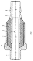
- Fig. 1 is a device according to the invention in longitudinal section or an anti-vibration nipple 1 shown, suitable for Connect a hydraulically or pneumatically operated Tool to a connecting coupling to the tool on a To connect the connecting or transport line in which the liquid or gaseous medium for operating the tool to be led.
- connection nipple 1 has a connection part 3, having a connection section 5, provided to to be connected to the tool. With section 5 it can a thread, a bayonet lock, a snap-in device and the like act to the connection nipple 1 firmly connected to the tool.
- the connector also points 3 a sleeve-like or cylinder-like design Section 9, which has an internal, cylindrical Section 17 encased on the outside, which is on the insertion part 11 is trained.
- the part 11 also has a nipple-like trained insertion section 13, provided to in a Recording or a coupling housing of the connecting coupling to be introduced.
- the insertion or nipple section 13 is trained so that it by means of locking members in the Recording or the clutch housing can be held firmly.
- the fixing of the plug nipple in the coupling should be on this Do not be discussed further as there are different Versions of such couplings are in which by plugging, Snapping in with swivel or rotary movements, by means of a bayonet lock and the like releasable connection between nipple and coupling is.
- the two cylinder-like or sleeve-like sections 9 and 17, between which a annular or sleeve-like space is formed, with one another via an elastomer material or an elastomer layer 19 are connected.
- This elastomer layer consisting of an elastomeric polymer or a rubber-like material suitable for vibrations or pulsations or striking movements, which from the tool via the connection section 5 be transferred to the connection nipple 1, at least partially to absorb or dampen.
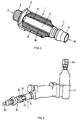
- FIG. 2 shows a specific embodiment of an inventive one Anti-vibration nipple 1 shown, with FIG. 1 analog parts are designated by the same reference numerals.
- This is clearly recognizable between the two cylindrical ones or sleeve-like sections 9 and 17 formed elastomer-like or rubber-like material 19 for damping or absorbing the striking movements or vibrations.
- the central, continuous bore 21 is clearly visible, which itself from the opening 7 in the connection section 5 to the opening 15 in the plug-in part 13 through the anti-vibration nipple 1 extends. Through this bore 21, the hydraulic or pneumatic medium led to drive the Tool.
- the anti-vibration nipple 1 according to FIG. 2 can for example from two metal parts 3 and 11 and a vulcanized Rubber with a given Shore hardness, such as a Shore hardness of approx. 50 - 55.
- the metal part 3 has an external or internal thread on the connection section 5 screwed into the corresponding threaded opening of the tool becomes.
- the other metal part 11 consists of the inner one sleeve-like or cylindrical part 17 and the other end 13, designed in the form of a nipple.
- the two parts are due to the vulcanization process, but flexible with each other connected so that vibrations and / or impacts do not hit the Coupling can be transferred.
- the construction method described prevents the anti-vibration nipple from lateral Forces are overused.
- the chosen elastomer material or the rubber quality, the Shore hardness and also the Overall length of the anti-vibration nipple determine its Mode of action as a so-called shock absorber between tools and clutch.
- FIG. 3 a striking end connected to a quick release coupling Tool shown in perspective view.
- the Pneumatic tool 41 can be, for example Act impact wrench, having an impact screw Mechanism 43 for attaching mounting screws at Assembling car wheels.
- the tool Fig. 2 known anti-vibration nipple 1, comprising the two sleeve-like or cylinder-like sections 9 and 17, which over the vulcanized rubber material, for example are connected.
- Quick release coupling 31 is a swivel coupling, in which the plug nipple perpendicular to the longitudinal axis the clutch is inserted into the clutch housing 33 and then by pivoting through 90 ° the locking elements Hold the nipple in the axial position. After locking can now the medium carried in the transport line 35, such as compressed air, on the air tool be transmitted.
- plug nipples without damping agents were already after 125 hours. Test duration defective or the leakage was so serious that the plug was unusable. Plug with damping Means as described in the prior art, i.e. in which applied to the elastomer material by means of a shrink ring were defective or unusable after 134 hours. In contrast to the plug nipple without damping agent, in which the leakage in the area of the clutch housing due to worn locking elements was determined, the test load resulted the nipple with damping agents to tear off in the area of the flexible material.
- FIGS. 1 to 3 only serves a better understanding of the present invention and thus represents only one possible embodiment, for example which is not a limitation for the present Invention is to be considered.
- the quick release coupling shown is only intended to serve using an example to demonstrate how an inventive Plug nipple can be connected to the coupling.
- the embodiment of the plug according to the invention or Anti-vibration nipples can be modified in any way modified or supplemented.
- Different elastomers, such as different layers can Elastomeric polymers, or rubbery materials, like the preferred vulcanized rubber materials.
- the choice of materials for the two is also based on the elastic material connected parts is in itself immaterial, come for it stainless steel, aluminum or other suitable metal Materials in question.
- Essential to the plug nipple proposed according to the invention is that what connects the two fixed structural parts Not elastic material, for example, by shrinking one Metal ring or a metal sleeve is subjected to force, but is obtained by pouring, spraying or extruding the elastomeric material or rubber and, if necessary, subsequent vulcanization or partial networking.
Landscapes
- Engineering & Computer Science (AREA)
- General Engineering & Computer Science (AREA)
- Mechanical Engineering (AREA)
- Percussive Tools And Related Accessories (AREA)
- Joints Allowing Movement (AREA)
- Pipe Accessories (AREA)
- Quick-Acting Or Multi-Walled Pipe Joints (AREA)
- Vibration Prevention Devices (AREA)
- Joints That Cut Off Fluids, And Hose Joints (AREA)
- Absorbent Articles And Supports Therefor (AREA)
- Materials For Medical Uses (AREA)
- Details Of Valves (AREA)
- Non-Disconnectible Joints And Screw-Threaded Joints (AREA)
Abstract
Description
- Fig. 1:
- eine erfindungsgemässe Vorrichtung bzw. einen Anschluss-Stecknippel im Längsschnitt,
- Fig. 2:
- einen Antivibrations-Nippel analog der Konstruktion aus Fig. 1 anhand eines konkreten Ausführungsbeispieles, wiederum teilweise aufgeschnitten, und
- Fig. 3:
- schematisch, in Perspektive, ein mittels eines erfindungsgemässen Antivibrations-Anschlusenippels an eine Schnellverschlusskupplung angeschlossenes schlagendes Werkzeug.
Claims (10)
- Vorrichtung zum Anschliessen eines pneumatisch oder hydraulisch betriebenen Werkzeuges an eine Verbindungskupplung (31) zur Herstellung der Verbindung mit einer flüssiges oder gasförmiges Medium führenden Transportleitung (35), gekennzeichnet durch mindestens einen ersten Teil (11), aufweisend einen Eingriffsabschnitt (13), vorgesehen, um in eine Aufnahme (33) an der Verbindungskupplung einführbar mit dieser wieder lösbar verbunden zu werden, einen zweiten Teil (3), aufweisend einen Anschlussabschnitt (5), ausgebildet, um mit dem Werkzeug fest verbunden zu werden, wobei die beiden Teile (3, 11) je mindestens einen weiteren Abschnitt (9, 17) aufweisen, von welchen der eine weitere Abschnitt (9) den anderen radial beabstandet aussen umhüllt und wobei zwischen den beiden weiteren Abschnitten eine elastische Verbindung (19) vorgesehen ist, welche Verbindung erhältlich ist durch Giessen, Spritzen oder Extrudieren eines elastischen, gummiartigen Materials zwischen die beiden Abschnitte.
- Vorrichtung, insbesondere nach Anspruch 1, dadurch gekennzeichnet, dass die beiden Abschnitte hülsenartig bzw. zylinderartig ausgebildet sind, aufweisend einen inneren Zylinder bzw. eine Hülse (17) mit einem kleineren Durchmesser und eine äussere Hülse bzw. einen Zylinder (9), aufweisend einen grösseren Durchmesser und mindestens teilweise umhüllend den inneren Zylinder bzw. die innere Hülse.
- Vorrichtung, insbesondere nach einem der Ansprüche 1 und 2, dadurch gekennzeichnet, dass der innere Zylinder bzw. die innere Hülse mit dem kleineren Durchmesser den weiteren Abschnitt (17) des ersten Teils (11) bildet.
- Vorrichtung, insbesondere nach einem der Ansprüche 1 oder 2, dadurch gekennzeichnet, dass die innere Hülse bzw. der Zylinder mit dem kleineren Durchmesser den weiteren Abschnitt des zweiten Teiles bildet.
- Vorrichtung, insbesondere nach einem der Ansprüche 1 bis 4, dadurch gekennzeichnet, dass das elastische gummiartige Material ein elastomeres Polymer ist.
- Vorrichtung, insbesondere nach einem der Ansprüche 1 bis 4, dadurch gekennzeichnet, dass das elastische, gummiartige Material ein kautschukartiger Gummi ist.
- Vorrichtung, insbesondere nach einem der Ansprüche 1 bis 6, dadurch gekennzeichnet, dass das elastische gummiartige Material wenigstens teilweise vernetzt und/oder aufvulkanisiert ist.
- Antivibrations-Nippel (1) zum Verbinden eines schlagenden bzw. vibrierenden, pneumatisch oder hydraulisch betriebenen Werkzeuges mit einer Schnellverschlusskupplung zum Anschliessen des Werkzeuges an eine flüssiges oder gasförmiges Medium führende Transportleitung mit einer Vorrichtung nach einem der Ansprüche 1 bis 7.
- Verfahren zum Dämpfen von schlagenden Bewegungen bzw. Vibrationen eines hydraulisch oder pneumatisch betriebenen Werkzeuges, dadurch gekennzeichnet, dass zwischen dem Werkzeug und einer Verbindungskupplung zum Anschliessen des Werkzeuges an eine das flüssige oder gasförmige Medium führende Transportleitung eine Vorrichtung zwischengeschaltet wird, aufweisend mindestens zwei Teile mit dazwischen angeordnet einer aus einem elastisch gummiartigen Material hergestellten Verbindung, wobei zum Herstellen der Verbindung der Zwischenraum zwischen den beiden Teilen der Vorrichtung ein elastomeres Polymermaterial oder ein gummiartiges Material eingegossen, eingespritzt oder einextrudiert wird und anschliessend gegebenenfalls teilvernetzt oder aufpolymerisiert wird.
- Verfahren, insbesondere nach Anspruch 9, dadurch gekennzeichnet, dass zum Einstellen der Dämpfung bzw. der Absorption der schlagenden Bewegung bzw. Vibration die elastische bzw. gummiartige Verbindung mit unterschiedlicher Shore-Härte versehen wird, beispielsweise durch Wahl unterschiedlicher polymerer Elastomermaterialien oder durch Wahl entsprechender gummiartiger Materialien und/oder unterschiedlichem Vernetzungs- bzw. Aufvulkanisationsgrad.
Priority Applications (14)
| Application Number | Priority Date | Filing Date | Title |
|---|---|---|---|
| ES98118680T ES2191238T3 (es) | 1998-10-02 | 1998-10-02 | Conector antivibracion. |
| PT98118680T PT990829E (pt) | 1998-10-02 | 1998-10-02 | Ligacao de encaixe antivibratoria |
| DE59806945T DE59806945D1 (de) | 1998-10-02 | 1998-10-02 | Antivibrations-Stecknippel |
| AT98118680T ATE231225T1 (de) | 1998-10-02 | 1998-10-02 | Antivibrations-stecknippel |
| EP98118680A EP0990829B1 (de) | 1998-10-02 | 1998-10-02 | Antivibrations-Stecknippel |
| JP2000574866A JP4450513B2 (ja) | 1998-10-02 | 1999-09-13 | 耐振動プラグニップル |
| BR9914134-5A BR9914134A (pt) | 1998-10-02 | 1999-09-13 | Dispositivo para a conexão de uma ferramenta operada pneumática ou hidraulicamente a um acoplamento de ligação, niple de anti-vibração e processo para o amortecimento de movimentos de impacto e vibrações de uma ferramenta operada hidráulica ou pneumaticamente |
| CA002346012A CA2346012C (en) | 1998-10-02 | 1999-09-13 | Anti-vibration plug-in nipple |
| AU55013/99A AU751181B2 (en) | 1998-10-02 | 1999-09-13 | Anti-vibration plug-in nipple |
| KR1020017004146A KR100591099B1 (ko) | 1998-10-02 | 1999-09-13 | 진동 방지 니플 |
| MXPA01003121A MXPA01003121A (es) | 1998-10-02 | 1999-09-13 | Niple enchufable antivibratorio. |
| CN99811693A CN1321231A (zh) | 1998-10-02 | 1999-09-13 | 防振动插接头 |
| PCT/CH1999/000429 WO2000020791A1 (de) | 1998-10-02 | 1999-09-13 | Antivibrations-stecknippel |
| ZA200102483A ZA200102483B (en) | 1998-10-02 | 2001-03-27 | Anti-vibration plug-in nipple. |
Applications Claiming Priority (1)
| Application Number | Priority Date | Filing Date | Title |
|---|---|---|---|
| EP98118680A EP0990829B1 (de) | 1998-10-02 | 1998-10-02 | Antivibrations-Stecknippel |
Publications (2)
| Publication Number | Publication Date |
|---|---|
| EP0990829A1 true EP0990829A1 (de) | 2000-04-05 |
| EP0990829B1 EP0990829B1 (de) | 2003-01-15 |
Family
ID=8232741
Family Applications (1)
| Application Number | Title | Priority Date | Filing Date |
|---|---|---|---|
| EP98118680A Expired - Lifetime EP0990829B1 (de) | 1998-10-02 | 1998-10-02 | Antivibrations-Stecknippel |
Country Status (14)
| Country | Link |
|---|---|
| EP (1) | EP0990829B1 (de) |
| JP (1) | JP4450513B2 (de) |
| KR (1) | KR100591099B1 (de) |
| CN (1) | CN1321231A (de) |
| AT (1) | ATE231225T1 (de) |
| AU (1) | AU751181B2 (de) |
| BR (1) | BR9914134A (de) |
| CA (1) | CA2346012C (de) |
| DE (1) | DE59806945D1 (de) |
| ES (1) | ES2191238T3 (de) |
| MX (1) | MXPA01003121A (de) |
| PT (1) | PT990829E (de) |
| WO (1) | WO2000020791A1 (de) |
| ZA (1) | ZA200102483B (de) |
Cited By (4)
| Publication number | Priority date | Publication date | Assignee | Title |
|---|---|---|---|---|
| EP1767843A2 (de) | 2005-09-22 | 2007-03-28 | HILTI Aktiengesellschaft | Schnellkupplungsanschlussteil mit Filter |
| EP3346174A1 (de) * | 2017-01-09 | 2018-07-11 | Hutchinson | Dichte anschlussvorrichtung zum fördern einer flüssigkeit |
| FR3107582A1 (fr) * | 2020-02-26 | 2021-08-27 | Psa Automobiles Sa | Raccord rapide de tuyaux avec anneau en elastomere donnant une flexibilite |
| US11448347B2 (en) * | 2018-06-13 | 2022-09-20 | Total Se | Tubular joint for an installation |
Families Citing this family (8)
| Publication number | Priority date | Publication date | Assignee | Title |
|---|---|---|---|---|
| KR100600209B1 (ko) | 2005-04-13 | 2006-07-13 | 현대자동차주식회사 | 파워 스티어링 펌프용 공진기 |
| GB2490263A (en) * | 2009-11-30 | 2012-10-24 | Zhik Pty Ltd | Waterproof breathable stretchable composite material |
| US8701848B2 (en) * | 2011-03-29 | 2014-04-22 | Gm Global Technology Operations | Sleeve damper assembly |
| CN105526446B (zh) * | 2014-09-30 | 2017-11-07 | 丹阳市腾辉液压机械有限公司 | 一种管接头预压紧装置 |
| CN105526447B (zh) * | 2014-09-30 | 2017-12-29 | 丹阳市腾辉液压机械有限公司 | 一种防振动密封管接头装置 |
| CN104930282A (zh) * | 2015-06-04 | 2015-09-23 | 王丽 | 一种防爆工业冷水机冷凝管连接头 |
| JP6565450B2 (ja) * | 2015-08-04 | 2019-08-28 | 日本製鉄株式会社 | 管継手 |
| DE102022132760A1 (de) * | 2022-12-09 | 2024-06-20 | Carl Freudenberg Kg | Steckverbinder |
Citations (2)
| Publication number | Priority date | Publication date | Assignee | Title |
|---|---|---|---|---|
| DE888786C (de) * | 1941-04-05 | 1953-09-03 | Clemens A Voigt | Gelenkverbindung fuer winkelbewegliche Rohrabschnitte von Druckmittelleitungen |
| CH518481A (de) * | 1969-09-18 | 1972-01-31 | Gebert & Cie | Im Zuge einer Fluidumsleitung anzuordnender Schalldämpfer |
-
1998
- 1998-10-02 AT AT98118680T patent/ATE231225T1/de active
- 1998-10-02 DE DE59806945T patent/DE59806945D1/de not_active Expired - Lifetime
- 1998-10-02 PT PT98118680T patent/PT990829E/pt unknown
- 1998-10-02 EP EP98118680A patent/EP0990829B1/de not_active Expired - Lifetime
- 1998-10-02 ES ES98118680T patent/ES2191238T3/es not_active Expired - Lifetime
-
1999
- 1999-09-13 JP JP2000574866A patent/JP4450513B2/ja not_active Expired - Fee Related
- 1999-09-13 WO PCT/CH1999/000429 patent/WO2000020791A1/de not_active Ceased
- 1999-09-13 BR BR9914134-5A patent/BR9914134A/pt not_active IP Right Cessation
- 1999-09-13 CA CA002346012A patent/CA2346012C/en not_active Expired - Fee Related
- 1999-09-13 CN CN99811693A patent/CN1321231A/zh active Pending
- 1999-09-13 KR KR1020017004146A patent/KR100591099B1/ko not_active Expired - Fee Related
- 1999-09-13 MX MXPA01003121A patent/MXPA01003121A/es not_active IP Right Cessation
- 1999-09-13 AU AU55013/99A patent/AU751181B2/en not_active Ceased
-
2001
- 2001-03-27 ZA ZA200102483A patent/ZA200102483B/en unknown
Patent Citations (2)
| Publication number | Priority date | Publication date | Assignee | Title |
|---|---|---|---|---|
| DE888786C (de) * | 1941-04-05 | 1953-09-03 | Clemens A Voigt | Gelenkverbindung fuer winkelbewegliche Rohrabschnitte von Druckmittelleitungen |
| CH518481A (de) * | 1969-09-18 | 1972-01-31 | Gebert & Cie | Im Zuge einer Fluidumsleitung anzuordnender Schalldämpfer |
Cited By (6)
| Publication number | Priority date | Publication date | Assignee | Title |
|---|---|---|---|---|
| EP1767843A2 (de) | 2005-09-22 | 2007-03-28 | HILTI Aktiengesellschaft | Schnellkupplungsanschlussteil mit Filter |
| EP1767843A3 (de) * | 2005-09-22 | 2007-12-19 | HILTI Aktiengesellschaft | Schnellkupplungsanschlussteil mit Filter |
| EP3346174A1 (de) * | 2017-01-09 | 2018-07-11 | Hutchinson | Dichte anschlussvorrichtung zum fördern einer flüssigkeit |
| FR3061757A1 (fr) * | 2017-01-09 | 2018-07-13 | Hutchinson | Dispositif de raccord etanche destine a vehiculer un fluide |
| US11448347B2 (en) * | 2018-06-13 | 2022-09-20 | Total Se | Tubular joint for an installation |
| FR3107582A1 (fr) * | 2020-02-26 | 2021-08-27 | Psa Automobiles Sa | Raccord rapide de tuyaux avec anneau en elastomere donnant une flexibilite |
Also Published As
| Publication number | Publication date |
|---|---|
| EP0990829B1 (de) | 2003-01-15 |
| JP2002538375A (ja) | 2002-11-12 |
| PT990829E (pt) | 2003-06-30 |
| KR100591099B1 (ko) | 2006-06-19 |
| CN1321231A (zh) | 2001-11-07 |
| WO2000020791A1 (de) | 2000-04-13 |
| AU751181B2 (en) | 2002-08-08 |
| AU5501399A (en) | 2000-04-26 |
| KR20010083883A (ko) | 2001-09-03 |
| CA2346012A1 (en) | 2000-04-13 |
| BR9914134A (pt) | 2001-06-19 |
| ATE231225T1 (de) | 2003-02-15 |
| JP4450513B2 (ja) | 2010-04-14 |
| MXPA01003121A (es) | 2002-04-24 |
| CA2346012C (en) | 2007-11-06 |
| ES2191238T3 (es) | 2003-09-01 |
| ZA200102483B (en) | 2002-01-02 |
| DE59806945D1 (de) | 2003-02-20 |
Similar Documents
| Publication | Publication Date | Title |
|---|---|---|
| EP0990829B1 (de) | Antivibrations-Stecknippel | |
| DE3606318C2 (de) | ||
| DE102008006030A1 (de) | Handwerkzeugmaschine, insbesondere elektrisch betriebene Handwerkzeugmaschine | |
| WO2016046020A1 (de) | Fadenverstärkte gelenkvorrichtung und kupplungsvorrichtung für einen fahrzeugantrieb | |
| DE102005003459B3 (de) | Elastischer Gelenkkörper | |
| WO2005059391A1 (de) | Drehgelenkkupplung zum gegenseitigen verbinden zweier wellenenden, insbesondere im antriebsstrang eines kraftfahrzeugs | |
| DE19820773C2 (de) | Gelenklager, insbesondere Federaugenlager | |
| EP3475678A1 (de) | Lauftrommelanordnung für einen reifenprüfstand sowie reifenprüfstand mit der lauftrommelanordnung | |
| DE3716941A1 (de) | Kupplung | |
| DE102012017319B4 (de) | Befestigungsanordnung zwischen einem Radiallager und einem Stützarm | |
| DE19927055A1 (de) | Seilzugbefestigung | |
| DE102005006480A1 (de) | Elastisches Lager | |
| EP0851824A1 (de) | Zugsattelzapfen für sattelanhänger und befestigungsanordnung | |
| DE19946923B4 (de) | Nabenabdeckung für eine Radlagerung, vorzugsweise für eine Nutzfahrzeug-Radlagerung | |
| EP3360702B1 (de) | Reifenventil für einen luftreifen eines fahrzeugs | |
| DE60107110T2 (de) | Sicherheitskupplung | |
| DE102008021207B4 (de) | Schwingungstilger mit einer Elastomerfeder | |
| DE3442518A1 (de) | Elastisch nachgiebiges lenkergelenk, insbesondere fuer achslenker von nutzfahrzeugen | |
| DE3936775A1 (de) | Elastisches kugelgelenk zur verbindung von maschinenelementen | |
| DE4301370A1 (en) | Vehicle towing hook or eye for use with plastics tow rope - uses holding element with threaded bolt and press fit bush | |
| EP1288538B1 (de) | Abstreifer | |
| EP1342539A1 (de) | Halterung für die Innendichtung an einem fluidbetriebenen Schlagwerk | |
| DE3520573A1 (de) | Elastische wellenkupplung | |
| DE29503151U1 (de) | Schwingungstilger | |
| DE602004012217T2 (de) | Überwurfmutter zur Verbindung von Rohren |
Legal Events
| Date | Code | Title | Description |
|---|---|---|---|
| PUAI | Public reference made under article 153(3) epc to a published international application that has entered the european phase |
Free format text: ORIGINAL CODE: 0009012 |
|
| AK | Designated contracting states |
Kind code of ref document: A1 Designated state(s): AT BE CH DE ES FR GB IT LI NL PT SE |
|
| AX | Request for extension of the european patent |
Free format text: AL;LT;LV;MK;RO;SI |
|
| 17P | Request for examination filed |
Effective date: 20000330 |
|
| AKX | Designation fees paid |
Free format text: AT BE CH DE ES FR GB IT LI NL PT SE |
|
| 17Q | First examination report despatched |
Effective date: 20011130 |
|
| GRAH | Despatch of communication of intention to grant a patent |
Free format text: ORIGINAL CODE: EPIDOS IGRA |
|
| GRAH | Despatch of communication of intention to grant a patent |
Free format text: ORIGINAL CODE: EPIDOS IGRA |
|
| GRAA | (expected) grant |
Free format text: ORIGINAL CODE: 0009210 |
|
| AK | Designated contracting states |
Kind code of ref document: B1 Designated state(s): AT BE CH DE ES FR GB IT LI NL PT SE |
|
| REG | Reference to a national code |
Ref country code: GB Ref legal event code: FG4D Free format text: NOT ENGLISH Ref country code: CH Ref legal event code: EP |
|
| REF | Corresponds to: |
Ref document number: 59806945 Country of ref document: DE Date of ref document: 20030220 Kind code of ref document: P |
|
| REG | Reference to a national code |
Ref country code: CH Ref legal event code: NV Representative=s name: TROESCH SCHEIDEGGER WERNER AG |
|
| REG | Reference to a national code |
Ref country code: SE Ref legal event code: TRGR |
|
| GBT | Gb: translation of ep patent filed (gb section 77(6)(a)/1977) |
Effective date: 20030519 |
|
| REG | Reference to a national code |
Ref country code: PT Ref legal event code: SC4A Free format text: AVAILABILITY OF NATIONAL TRANSLATION Effective date: 20030415 |
|
| REG | Reference to a national code |
Ref country code: ES Ref legal event code: FG2A Ref document number: 2191238 Country of ref document: ES Kind code of ref document: T3 |
|
| ET | Fr: translation filed | ||
| PLBE | No opposition filed within time limit |
Free format text: ORIGINAL CODE: 0009261 |
|
| STAA | Information on the status of an ep patent application or granted ep patent |
Free format text: STATUS: NO OPPOSITION FILED WITHIN TIME LIMIT |
|
| 26N | No opposition filed |
Effective date: 20031016 |
|
| PGFP | Annual fee paid to national office [announced via postgrant information from national office to epo] |
Ref country code: PT Payment date: 20100928 Year of fee payment: 13 Ref country code: NL Payment date: 20101009 Year of fee payment: 13 Ref country code: FR Payment date: 20101020 Year of fee payment: 13 Ref country code: AT Payment date: 20101020 Year of fee payment: 13 |
|
| PGFP | Annual fee paid to national office [announced via postgrant information from national office to epo] |
Ref country code: CH Payment date: 20101019 Year of fee payment: 13 |
|
| PGFP | Annual fee paid to national office [announced via postgrant information from national office to epo] |
Ref country code: BE Payment date: 20101020 Year of fee payment: 13 Ref country code: IT Payment date: 20101015 Year of fee payment: 13 Ref country code: GB Payment date: 20101019 Year of fee payment: 13 Ref country code: SE Payment date: 20101019 Year of fee payment: 13 |
|
| PGFP | Annual fee paid to national office [announced via postgrant information from national office to epo] |
Ref country code: DE Payment date: 20101213 Year of fee payment: 13 |
|
| PGFP | Annual fee paid to national office [announced via postgrant information from national office to epo] |
Ref country code: ES Payment date: 20101122 Year of fee payment: 13 |
|
| REG | Reference to a national code |
Ref country code: PT Ref legal event code: MM4A Free format text: LAPSE DUE TO NON-PAYMENT OF FEES Effective date: 20120402 |
|
| BERE | Be: lapsed |
Owner name: HANS *OETIKER A.G. MASCHINEN- UND APPARATEFABRIK Effective date: 20111031 |
|
| REG | Reference to a national code |
Ref country code: NL Ref legal event code: V1 Effective date: 20120501 |
|
| REG | Reference to a national code |
Ref country code: CH Ref legal event code: PL |
|
| GBPC | Gb: european patent ceased through non-payment of renewal fee |
Effective date: 20111002 |
|
| REG | Reference to a national code |
Ref country code: SE Ref legal event code: EUG |
|
| REG | Reference to a national code |
Ref country code: FR Ref legal event code: ST Effective date: 20120629 |
|
| PG25 | Lapsed in a contracting state [announced via postgrant information from national office to epo] |
Ref country code: DE Free format text: LAPSE BECAUSE OF NON-PAYMENT OF DUE FEES Effective date: 20120501 Ref country code: LI Free format text: LAPSE BECAUSE OF NON-PAYMENT OF DUE FEES Effective date: 20111031 Ref country code: BE Free format text: LAPSE BECAUSE OF NON-PAYMENT OF DUE FEES Effective date: 20111031 Ref country code: NL Free format text: LAPSE BECAUSE OF NON-PAYMENT OF DUE FEES Effective date: 20120501 Ref country code: CH Free format text: LAPSE BECAUSE OF NON-PAYMENT OF DUE FEES Effective date: 20111031 |
|
| REG | Reference to a national code |
Ref country code: DE Ref legal event code: R119 Ref document number: 59806945 Country of ref document: DE Effective date: 20120501 |
|
| PG25 | Lapsed in a contracting state [announced via postgrant information from national office to epo] |
Ref country code: GB Free format text: LAPSE BECAUSE OF NON-PAYMENT OF DUE FEES Effective date: 20111002 Ref country code: FR Free format text: LAPSE BECAUSE OF NON-PAYMENT OF DUE FEES Effective date: 20111102 Ref country code: PT Free format text: LAPSE BECAUSE OF NON-PAYMENT OF DUE FEES Effective date: 20120402 Ref country code: IT Free format text: LAPSE BECAUSE OF NON-PAYMENT OF DUE FEES Effective date: 20111002 |
|
| PG25 | Lapsed in a contracting state [announced via postgrant information from national office to epo] |
Ref country code: SE Free format text: LAPSE BECAUSE OF NON-PAYMENT OF DUE FEES Effective date: 20111003 |
|
| REG | Reference to a national code |
Ref country code: AT Ref legal event code: MM01 Ref document number: 231225 Country of ref document: AT Kind code of ref document: T Effective date: 20111002 |
|
| PG25 | Lapsed in a contracting state [announced via postgrant information from national office to epo] |
Ref country code: AT Free format text: LAPSE BECAUSE OF NON-PAYMENT OF DUE FEES Effective date: 20111002 |
|
| REG | Reference to a national code |
Ref country code: ES Ref legal event code: FD2A Effective date: 20130606 |
|
| PG25 | Lapsed in a contracting state [announced via postgrant information from national office to epo] |
Ref country code: ES Free format text: LAPSE BECAUSE OF NON-PAYMENT OF DUE FEES Effective date: 20111003 |