EP0989736B1 - Procédé et dispositif de contrôle d'un laser avec un seuil de niveau de courant - Google Patents
Procédé et dispositif de contrôle d'un laser avec un seuil de niveau de courant Download PDFInfo
- Publication number
- EP0989736B1 EP0989736B1 EP19980203266 EP98203266A EP0989736B1 EP 0989736 B1 EP0989736 B1 EP 0989736B1 EP 19980203266 EP19980203266 EP 19980203266 EP 98203266 A EP98203266 A EP 98203266A EP 0989736 B1 EP0989736 B1 EP 0989736B1
- Authority
- EP
- European Patent Office
- Prior art keywords
- laser
- image
- driving current
- radiation
- threshold current
- Prior art date
- Legal status (The legal status is an assumption and is not a legal conclusion. Google has not performed a legal analysis and makes no representation as to the accuracy of the status listed.)
- Expired - Lifetime
Links
Images


Classifications
-
- H—ELECTRICITY
- H04—ELECTRIC COMMUNICATION TECHNIQUE
- H04N—PICTORIAL COMMUNICATION, e.g. TELEVISION
- H04N1/00—Scanning, transmission or reproduction of documents or the like, e.g. facsimile transmission; Details thereof
- H04N1/40—Picture signal circuits
- H04N1/40025—Circuits exciting or modulating particular heads for reproducing continuous tone value scales
- H04N1/4005—Circuits exciting or modulating particular heads for reproducing continuous tone value scales with regulating circuits, e.g. dependent upon ambient temperature or feedback control
-
- G—PHYSICS
- G06—COMPUTING; CALCULATING OR COUNTING
- G06K—GRAPHICAL DATA READING; PRESENTATION OF DATA; RECORD CARRIERS; HANDLING RECORD CARRIERS
- G06K15/00—Arrangements for producing a permanent visual presentation of the output data, e.g. computer output printers
- G06K15/02—Arrangements for producing a permanent visual presentation of the output data, e.g. computer output printers using printers
- G06K15/12—Arrangements for producing a permanent visual presentation of the output data, e.g. computer output printers using printers by photographic printing, e.g. by laser printers
- G06K15/1204—Arrangements for producing a permanent visual presentation of the output data, e.g. computer output printers using printers by photographic printing, e.g. by laser printers involving the fast moving of an optical beam in the main scanning direction
- G06K15/1209—Intensity control of the optical beam
- G06K15/1214—Intensity control of the optical beam by feedback
-
- H—ELECTRICITY
- H04—ELECTRIC COMMUNICATION TECHNIQUE
- H04N—PICTORIAL COMMUNICATION, e.g. TELEVISION
- H04N1/00—Scanning, transmission or reproduction of documents or the like, e.g. facsimile transmission; Details thereof
- H04N1/40—Picture signal circuits
- H04N1/40025—Circuits exciting or modulating particular heads for reproducing continuous tone value scales
- H04N1/40037—Circuits exciting or modulating particular heads for reproducing continuous tone value scales the reproducing element being a laser
Definitions
- the present invention relates to an image exposure device using a laser; more specifically the present invention is related to controlling the driving current applied to the laser.
- a conventional image exposure device as used e.g. in an electrophotographic printer or in an imagesetter, an image is formed on a radiation-sensitive body by exposing the body image-wise by a laser beam from a laser.
- the image on the radiation-sensitive body is a latent image, which is developed into a visible toner image, that is subsequently transferred to an image carrier such as a sheet of paper.
- the radiation-sensitive body usually is the image carrier itself, such as a roll of photographic film; on the film, a latent image is exposed, that is afterwards developed in a processor into a visible image.
- the laser in the image exposure device may be a semiconductor laser; the laser beam is modulated based on an image signal that corresponds to the image.
- a semiconductor laser has a threshold current level I th (expressed e.g. in mA).
- I th (expressed e.g. in mA).
- a laser beam is emitted if the electrical driving current I applied to the laser is larger than the threshold current level I th .
- Fig. 1a shows two curves, one for a low temperature and one for a high temperature, with corresponding threshold current levels I thLOW and I thHIGH ; the temperature dependence of I th is discussed below.
- the radiation intensity RI (expressed e.g. in mW) of the radiation emitted by the laser is very small, and in fact, the emitted radiation is not coherent, i.e. it is not really laser radiation.
- the portions of the curves for I larger than I th are useful for imaging purposes; therefore the portions of the curves in Fig. 1a for I smaller than I th are drawn as dashed lines.
- the driving current I that is applied to the laser is modulated based on the image signal, so that the intensity RI of the emitted laser beam is a function of the image signal.
- the laser threshold current level I th is not constant, but depends on different factors, such as the ambient temperature, the ageing of the laser, differences between individual lasers. Fluctuations in the threshold current level cause significant variations of the laser beam intensity; as shown in Fig. 1a , the threshold current level changes from I thLOW to I thHIGH when temperature changes from low to high.
- the intensity RI of the laser beam should depend only on the image signal and should not change with the factors influencing the threshold current level I th . Therefore, it is customary to control the laser, usually by means of a feedback circuit as known in system control theory. Customarily the required intensity of the laser beam is determined and a signal based on the measured intensity is fed back to the driving circuit of the laser in order to control the laser driving current. In this way, the effect of disturbances, influencing e.g. the laser threshold current level, can be reduced.
- Fig. 1a Two known methods to control the laser are illustrated by means of Fig. 1a .
- a first method the laser is driven from point O to point B in one step; in a second method the laser is driven from O to B via A in three steps. Both methods are now discussed in detail.
- the laser starts from zero driving current and zero radiation intensity in point O, and the laser driving current is increased until the driving current corresponding to point B is reached.
- a disadvantage of this first method is that it takes a long time for the driving current to reach point B, since the operating point of the laser must pass the whole way from O via A to B (see Fig. 1a ). Because of the long time that is required, the imaging speed is limited.
- the laser is driven from O to B via A in three steps.
- the laser is driven from O to A.
- the laser is kept at point A, until an image, or more precisely, until a non-zero portion of an image has to be written.
- the laser is driven from A to B.
- Essential in this method is that, beforehand, the driving current is set to an initial driving current that equals the threshold current level I thLOW before the image is written.
- the advantage is that, when an image is to be written, the laser reacts promptly to the change in laser driving current corresponding to a change from point A to point B, thus overcoming the problem of the limited imaging speed of the first method.
- a disadvantage of this second method is that the laser is kept for some time at operating point A, which means that some radiation is being emitted before the actual image is written. This means that the radiation-sensitive body is exposed by the radiation emitted in A. Therefore, specific countermeasures may have to be taken; in order to avoid that an image is formed by the radiation emitted in A, in an electrophotographic printer for example the electrophotographic parameters such as the cleaning potential may be adjusted (the cleaning potential is discussed e.g. in EP-A-0 788 273 ). However, these countermeasures have drawbacks (adjusting the cleaning potential, for example, may result in increased carrier loss).
- the driving current instead of setting the driving current to an initial value that equals the threshold current, the driving current may be set to a value about the threshold current value, or, alternatively, the driving current may be set to a value below the threshold current value.
- the problems of the first and the second method discussed above are either the limited imaging speed, or undesired emitted radiation, or both.
- Patent US-A-5 416 504 discloses an image exposure device that implements another variant of the second method discussed above (the second method involves driving the laser to B in Fig. 1a in three steps: driving the laser from O to A; keeping the laser in A; driving the laser from A to B).
- the initial driving current is set about the threshold current level of the semiconductor laser (i.e. the laser is driven from O to about point A in Fig. 1a ) in two substeps: first the driving current is set to a first value near the threshold current level, using the output of a counter circuit, and then the driving current is adjusted to a second value about the threshold current level by incrementing or decrementing this counter.
- the counter is incremented or decremented depending on the difference between a reference voltage and a monitor voltage that indicates the actual laser beam intensity and that is obtained as follows: the light from the laser is input to a monitor diode; the monitor diode outputs a current that is converted to the monitor voltage. When the monitor voltage equals the reference voltage, this indicates that the laser beam has reached a predetermined intensity. Finally, in order to write an image, the input image signal is added to the counter output value (the counter output value corresponding to the above second value of the driving current) and the sum is converted into an electrical current for driving the laser.
- the counter output can only change gradually; the purpose hereof is to stabilise the control of the driving current.
- the laser beam is monitored only during the time that no image signal is applied to the laser; there is no feedback during exposure of the image.
- a disadvantage of this device is, as mentioned above, that undesired radiation is emitted which exposes the radiation-sensitive body.
- Another disadvantage is the high complexity of the circuitry that controls the laser driving current.
- Yet another disadvantage is that there is no feedback, and hence disturbances - influencing e.g. the laser threshold current level - are not coped with during image exposure.
- European application EP-A-0, 548, 591 discloses an image exposure device that also implements an example of the second method disclosed above.
- Another object is to provide a method for controlling the radiation intensity of a laser beam, that can be implemented in a simple and cost-effective way.
- Another object is to provide a method for generating a high quality image.
- An electrical driving current I "about" the threshold current level I th fulfils the following relation, wherein RI is the radiation intensity emitted at the driving current I, and RI max is the maximum value of the radiation intensity RI for the laser that is preferably not exceeded so as not to reduce the laser life:
- a "substantially zero" electrical driving current is a current for driving a laser that is preferably smaller than 25 % of the threshold current level I th of the laser, more preferably smaller than 10 % of I th , most preferably less than 5 % of I th .
- a "pixel” is a constituting element of a digital image; a digital image is typically represented by a rectangular matrix of pixels, each having an electronic pixel value. The location of each pixel within the matrix corresponds to a specific location on the image carrier. These locations may be equidistant or not. Each electronic pixel value corresponds to an optical density of the image at the specific location; the electronic pixel values together form the image signal that is used for driving the laser.
- a "binary pixel" can have two electronic pixel values, customarily represented by 0 and 1; these two values represent a high density and a low density, which may be obtained e.g. by applying toner or no toner, or generating locally dye or no dye, or by keeping or removing silver in a photographic process.
- 0 may result in an ink repellent zone
- 1 may result in an ink accepting zone.
- a “continuous tone system” is a system wherein multiple density levels may be generated on the image carrier, with no perceptible quantisation to them. In order to achieve such fine quantisation, usually 256 different density levels are required, such that each "continuous tone pixel" may have a value from 0 to 255.
- a “multilevel system” has a reduced number of density levels.
- electrophotography e.g., usually a reduced number of density levels can be generated consistently, e.g. 16 levels; such a system is called a “multilevel system” and the pixels are called “multilevel pixels”.
- a “radiation-sensitive means” comprises a material that is sensitive to electromagnetic radiation.
- the radiation-sensitive means may be a photoconductive member, such as a photoconductive drum or belt, as used in an electrophotographic apparatus. It may also be a radiation-sensitive sheet, such as a photographic or a thermographic sheet.
- the electromagnetic radiation may be visible light, but it may also be invisible radiation, such as ultraviolet or infrared radiation.
- a “radiation-sensitive sheet” may be a cut sheet or a sheet on roll that has a length of e.g. 100 m.
- the sheet may be made of film, such as poly (ethylene terephtalate) film, it may be made of paper, of (aluminium) plate, or of another radiation-sensitive material as known in the art.
- the laser is driven (see Fig. 1a ) directly from O to B via A in two steps: first the laser is driven from O to A, and then, in a second step immediately after the first step, the laser is driven from A to B.
- the first step is controlled by a first electrical signal and the second step is controlled by a second electrical signal, wherein the second electrical signal is relatively independent from the first electrical signal.
- the first prior art method discussed above drives the laser from O to B in only one step.
- the second prior art method discussed above drives the laser from O to B in three steps while keeping the laser for some time in or near A, until an image has to be written.
- the driving current is not set to an initial driving current at or near A before the image is written; this significantly reduces the emission of undesired radiation, as discussed below, and is another advantage of the present invention.
- the laser is kept for some time at point A (see Fig. 1a ), thus emitting undesired radiation; a measure for the time during which undesired radiation is emitted is the time t keep , defined as follows.
- the image is exposed scan-wise, i.e. as a succession of scan lines (a scan line is shown in Fig. 2 as the line along arrow B on the surface of drum 15; Fig. 2 is discussed hereinafter).
- the time t between of the scan line is defined as the maximum time between two successive non-zero image portions in the scan line.
- the time t max of an image is defined as the maximum value of the t between -values of the scan lines of the image (only the scan lines with at least two non-zero image portions).
- t keep is the mean value of the t max -values of a set of representative images that are to be exposed by the laser.
- t keep as defined above is the maximum time that is typically to be expected between two non-zero image portions; during this time, the laser is kept at point A in the second prior art method and undesired radiation is emitted.
- the laser driving current is increased to about the threshold current level in a time t inc that is substantially smaller than t keep ; substantially smaller means that t inc is smaller than 50 % of t keep , preferably smaller than 30 % of t keep , more preferably smaller than 20 % of t keep , most preferably smaller than 10 % of t keep .
- the laser driving current I increases in a time t inc in a substantially linear way from zero to the threshold current level I th .
- the relation between driving current I and time is linear, and that the relation between radiation intensity RI and driving current I is also linear (i.e. portion OA of the curve in Fig. 1a is part of a straight line).
- the relation between radiation intensity RI and time is also linear, as shown in Fig. 1b
- the quantity of emitted undesired radiation, i.e. the (radiant) exposure is the integral under the curve in Fig. 1b , which equals the area 31 of the hatched triangle: 0.5 * t inc * Intensity A
- the laser is kept at point A, and t keep as defined above is a measure for the time during which undesired radiation is emitted.
- t keep a quantity of undesired radiation is emitted at A that equals the area 32 of the hatched rectangle in Fig. 1c : t keep * Intensity A
- the area 31 is significantly smaller than the area 32, since the area of a triangle is only half of the area of a rectangle that has the same base, and since moreover, as discussed above, t inc is preferably substantially smaller than t keep .
- the laser driving current increases in another than a linear way from zero to the threshold current level I th , e.g. in a parabolic way, the quantity of undesired emitted radiation is significantly smaller than in the second prior art method: the surface 31 of the triangle in Fig. 1b then has to be replaced by the surface below e.g. a parabola.
- the method of the present invention may be implemented in an image exposure device.
- Preferred embodiments of the method may be implemented in preferred embodiments of the image exposure device, and preferred embodiments of the image exposure device may result in preferred embodiments of the method of the present invention. Some preferred embodiments of method and device are discussed below.
- increasing the driving current up to about the threshold current level is achieved by a driving signal "d fatzero " immediately before the image has to be written.
- the magnitude and the time duration of "d fatzero" are determined so that the driving current increases up to about the threshold current level.
- the driving current is quickly decreased after an image is written. This may be achieved by applying a signal "d backbias " as discussed hereinafter.
- An advantage of a preferred embodiment in accordance with the present invention is that a high quality image can be generated. This may be achieved by keeping the laser driving current well under control, preferably before the image is written (e.g. by means of a signal "d fatzero ", as explained hereinafter), as well as after the image is written (e.g. by means of a signal “d backbias ", as explained hereinafter), and by reducing the emitted undesired radiation.
- the exposed image comprises binary pixels. In another embodiment, the image comprises multilevel pixels. In yet another embodiment, the image comprises continuous tone pixels.
- the feedback circuit is active during exposure. This provides the advantage that the radiation intensity of the laser beam may be adjusted during a scan line ( Fig. 2 , discussed hereinafter, shows a scan line as the line along arrow B on the surface of drum 15).
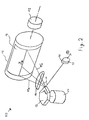
- FIG. 2 An embodiment of an image exposure device 50 is shown in Fig. 2 .
- a laser beam 11 is emitted by a semiconductor laser 10 and is focused and caused to move by an optical system to scan the surface of a photoconductive drum 15.
- the optical system includes a collimator lens, not shown, a polygonal mirror 13 driven by motor 17 and rotating in the direction A and an f- ⁇ lens 14.
- the laser beam 11 scans the surface of photoconductive drum 15 between the extreme beam positions 11a and 11b and thus exposes a scan line along arrow B on the surface of drum 15.
- Drum 15 is rotated by motor 18 so that successive scan lines form a latent image 16 on the surface of the drum 15.
- Monitor diode 12 at the back of semiconductor laser 10 provides a signal f that is proportional to the radiation intensity RI of the radiation emitted by laser 10.
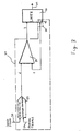
- FIG. 3 An embodiment of a driving circuit for laser 10, in accordance with the present invention, is shown schematically in Fig. 3 .
- the embodiment comprises driving means 21, that preferably include feedback means 23 and comparing means 24.
- the signal f (see Fig. 2 and 3 ) from monitor diode 12 is fed back by feedback means 23 to comparing means 24 where it is compared to a driving signal d.
- Driving means 21 outputs an electrical driving current I to laser 10 that depends on the difference d - f: preferably, the rate of change of driving current I is proportional to d - f. When d - f ⁇ 0, the driving current I will decrease; when d - f > 0, I will increase.
- the driving signal d is based on the image signal 20 and on a plurality of control signals 27.
- the image signal 20 and the control signals 27 are digital signals that are converted to an analog driving signal d via a digital-to-analog converter 25.
- the image signal 20 and/or the control signals 27 may also be analog signals.
- Fig. 4a to 4c illustrate an embodiment in accordance with the present invention wherein the laser driving current I is increased to about the threshold current level I th by applying a signal "d fatzero " during a time t inc that equals the pixel period t pix , i.e. the time it takes to write a pixel.
- Fig. 4b shows a driving signal d.
- the driving signal d causes laser 10, as shown in Fig. 3 , to be supplied with a driving current I, for writing a pixel having an electronic pixel value p.
- Fig. 4b and 4c show the values of d, f and I, that correspond to the specific image signal 20 shown in Fig.
- the image signal 20 is zero during the first two pixel periods, equals p during the third pixel period, and is again zero during the fourth and the fifth pixel periods.
- the image signal 20 is combined with control signals 27, as shown in Fig. 3 , to form the driving signal d.
- Fig. 4b and 4c show that d equals d off during the first pixel period; the driving current I is zero, the laser does not emit radiation and feedback signal f is zero.
- the value d off may be zero. How the value d off is determined, and how the other values d p , d fatzero and d backbias are determined, is discussed below.
- d d fatzero .
- the value d fatzero is determined so that at the end of the pixel period the feedback signal f has hardly increased and the driving current I approximately equals the threshold current level I th .
- the third pixel is the actual image pixel.
- the driving signal d now equals d p . Since I approximately equals I th at the start of the image pixel, the driving current I quickly increases to the driving current value that corresponds to the desired laser beam intensity.
- the laser emits a laser beam and feedback signal f increases until f equals d p ; from that moment on, the driving current I and the laser beam intensity remain constant.
- the driving current I decreases quickly; the driving current I preferably decreases about as fast as it increased in the second pixel period, i.e. the pixel period of d fatzero .
- the idea behind signal d backbias is the same as the idea behind d fatzero : passing quickly through the region of undesired emitted radiation, i.e. portion OA of the curve in Fig. 1a .
- Fig. 5a to 5c show this remaining case.
- the driving signal d equals a value d midzero - determined below - that may differ from d off , since the driving current I is preferably not decreased to zero but kept at a "standby" value about the threshold current level I th , so that the driving current I can promptly increase again to write the second image pixel p2.
- the electronic pixel values p1 and p2, shown in Fig. 5a may differ from each other.
- Fig. 5a to 5c show the image signal 20 and signals d, f and I as in Fig. 4a to 4c .
- the driving signal d subsequently gets the values d off , d fatzero , d p1 , d midzero , d p2 , d backbias ; except for d midzero , these values are not indicated in Fig. 5b .
- the values of d off , d fatzero , d backbias , d midzero and d p may be determined as follows. Preferably, these values are determined before or after an image is exposed, i.e. not during image exposure. Preferably, determination of these values is repeated at regular time intervals. The length of these time intervals may differ for each value, e.g. d fatzero may be determined more often than d off . The length of the time intervals depends on the effect that each value has on the laser control system and on the relation of each value with disturbances, such as the ambient temperature and the ageing of the laser; e.g. d fatzero is directly related to I th which is very much temperature-dependent; therefore d fatzero is preferably determined frequently, e.g. every time after a single image is written.
- d off d 0 - off_offset, wherein off_offset > 0 and off_offset ⁇ do.
- d fatzero and d backbias may be determined as illustrated in Fig. 6a and 6b.
- Fig. 6a shows the driving signal d and the feedback signal f
- Fig. 6b shows the driving current I as a function of time, represented in the same way as in Fig. 4a to 4c and Fig. 5a to 5c .
- a driving signal d as shown in Fig. 6a is applied, wherein d fatzero successively gets increasing values, e.g. d off , d off + 1, d off + 2, etc. until feedback signal f > f th , wherein f th is a very small positive value.
- the value of f th may be determined so that the corresponding driving current I equals I th .
- d midzero may equal d off .
- d midzero may be chosen so that it certainly makes the driving current decrease and that the driving current decreases as slowly as possible; in this way, it is known what is the value of the driving current in the "midzero" pixel.
- d midzero may be chosen so that feedback signal f has a predetermined value at the end of the "midzero" pixel, i.e. at the end of the fourth pixel period in Fig. 5a to 5c .
- the value of d p may be determined in two steps: first a value d pmax is determined, and then d p is determined by scaling with respect to d pmax .
- the value d pmax may correspond to the maximum driving current I max and the maximum radiation intensity RI max of the laser; I max and RI max are e.g. values that are preferably not exceeded so as not to reduce the laser life.
- d fatzero may be determined by first determining the threshold current level I th , and by subsequently increasing the driving signal d step by step while measuring I; the value of d where I approximately equals I th is d fatzero .
- First determining I th may be done by increasing the driving signal d step by step, and measuring the feedback signal f and the driving current I; I th is the driving current where the relation between I and f changes abruptly (see also Fig. 1a ).
- the laser driving current I is increased to about the threshold current level I th by applying a signal "d fatzero " during a time t inc equal to the pixel period t pix .
- t inc may be smaller than t pix , or, alternatively, t inc may be larger than t pix .
- t inc is substantially smaller than the maximum time t keep that is typically to be expected between two non-zero image portions; however, t inc may be larger than t pix , equal to t pix or smaller than t pix .
- the laser driving current is increased to about the threshold current level by applying a signal "d fatzero " during a time t inc longer than t pix , e.g. equal to 2*t pix .
- a signal "d fatzero" is applied for a longer time, e.g. for two pixel periods t pix .
- the signal d fatzero need not be constant but may have two or more values, that preferably increase during the successive pixel periods.
- portion OA of the curve Because of the high gain in portion OA of the curve, the portion OA is passed through quickly, which, together with the immediate further increase of the driving current in the second step, again provides the advantages of significantly reducing the emission of undesired radiation and of promptly driving the laser to the desired radiation strength.
- the gain is lower in the second step, because a high gain would make the feedback circuit unstable, since the laser beam intensity strongly increases with increasing driving current above the threshold current level (see also the strongly increasing curve AB in Fig. 1b ).
- the present invention is not limited to the embodiments discussed above, but includes other embodiments, such as the ones outlined below.
- the feedback signal is not necessarily proportional to the radiation intensity of laser beam 11; the relationship may e.g. be parabolic instead of linear. Also, for a radiation intensity of zero, the feedback signal is not necessarily zero but may have an offset value differing from zero. Furthermore, instead of the radiation intensity, another quantity, such as the driving current, may be fed back to the laser control system. Alternatively, more than one quantity may be fed back, such as both the radiation intensity and the driving current. In still another embodiment in accordance with the present invention, the feedback means need not be active during exposure but may only be active when no image is being exposed. In this embodiment, the driving signal d fatzero may be converted directly, i.e.
- driving signal d p may directly drive the driving current to a desired level; when no image is being exposed, feedback may be used to determine the values of the control signals such as d fatzero ; this determination may be carried out as explained above.
- the image signal 20 and the control signals 27 are not necessarily digital signals but may be analog signals; thus, the image 16 is not necessarily constituted of (digital) pixels but it may be an analog image as well.
- the electrical driving current in a first step increases up to about the threshold current and then in a second step immediately further increases above the threshold current level, without remaining at or about the threshold current level.
- the increase up to about the threshold current level may be accomplished, as discussed above, by applying a signal d fatzero , but it is clear to those skilled in the art that numerous other ways of increasing the driving current are possible.
- a method in accordance with the present invention may be implemented in an image exposure device, as is used e.g. in an electrophotographic printer or in an imagesetter.
- the electrophotographic printer has a photoconductive member, such as a photoconductive drum or a photoconductive endless belt, that is exposed by the image exposure device.
- the electrophotographic printer may be a black and white printer, a colour printer, a multi-grey printer.
- a radiation-sensitive sheet may be exposed by visible light, by infrared radiation, by ultraviolet radiation, emitted by the image exposure device.
- the laser beam controlled by a method in accordance with the present invention, may also be used for other purposes wherein no image is formed.
- the emitted laser beam may be reflected, at least partially, by an optical medium and the reflected beam may be analysed.
- a method in accordance with the present invention may be applied to control a semiconductor laser.
- the laser may emit visible light, but it may also emit other electromagnetic radiation, such as ultraviolet or infrared radiation.
- the laser is not necessarily a semiconductor laser; a method of the present invention may be applied for any laser or for any source of radiation that exhibits a threshold behaviour.
- the threshold behaviour must be such that - see also Fig. 1a - the curve showing the radiation intensity as a function of a driving parameter, such as the electrical driving current, exhibits an abrupt change about the threshold value from a low gradient to a high gradient.
Claims (10)
- Procédé de commande d'une intensité de rayonnement d'un faisceau laser (11) dans un dispositif d'exposition d'image, le faisceau laser (11) étant émis par un laser (10) ayant un niveau de courant de seuil au-dessus duquel le laser (10) émet ledit faisceau laser (11), le procédé consistant à :- à une première étape, délivrer un courant électrique de commande pour commander ledit laser (10), ledit courant électrique de commande augmentant à peu près jusqu'au dit niveau de courant de seuil ;- à une deuxième étape, augmenter davantage ledit courant électrique de commande à une valeur au-dessus dudit niveau de courant de seuil pour amener ledit laser (10) à émettre ledit faisceau laser (11) ; et- à une troisième étape, diminuer ledit courant électrique de commande à une valeur inférieure à 25 % du courant de seuil ;dans lequel la première étape est commandée par un premier signal de commande (d) et la deuxième étape est commandée par un deuxième signal de commande (d) différent, et la troisième étape est commandée par un troisième signal de commande (d) différent.
- Procédé selon la revendication 1, dans lequel ledit courant électrique de commande augmente à partir d'une valeur inférieure à 25 % du courant de seuil.
- Procédé selon l'une quelconque des revendications précédentes, dans lequel ledit courant électrique de commande augmente à peu près jusqu'au dit niveau de courant de seuil dans un temps tinc, et dans lequel ladite troisième étape comprend :- la diminution dudit courant électrique de commande à la valeur inférieure à 25 % du niveau de courant de seuil dans un temps qui n'est pas supérieur à deux fois ledit temps tinc.
- Dispositif d'exposition d'image (50) comprenant :- des moyens sensibles à un rayonnement (15) ;- un laser (10) pour émettre un faisceau laser (11) pour exposer lesdits moyens sensibles à un rayonnement (15) pour former une image (16) sur ceux-ci ; et- des moyens de commande (21) pour commander ledit laser (10) avec un courant électrique de commande basé sur un signal d'image (20) correspondant à ladite image (16) ;dans lequel ledit laser (10) a un niveau de courant de seuil au-dessus duquel le laser (10) émet ledit faisceau laser (11) ;
caractérisé en ce que lesdits moyens de commande (21) comprennent :des moyens, sensibles à un premier signal de commande, configurés pour augmenter ledit courant électrique de commande à peu près jusqu'au dit niveau de courant de seuil ;des moyens, sensibles à un deuxième signal de commande différent, configurés pour augmenter davantage ledit courant électrique de commande à une valeur au-dessus dudit niveau de courant de seuil pour amener ledit laser (10) à émettre ledit faisceau laser (11) ; etdes moyens, sensibles à un troisième signal de commande différent, configurés pour diminuer ledit courant électrique de commande à une valeur inférieure à 25 % du courant de seuil. - Dispositif d'exposition d'image (50) selon la revendication 4, dans lequel ledit courant électrique de commande augmente à partir d'une valeur inférieure à 25 % du courant de seuil.
- Dispositif d'exposition d'image (50) selon l'une quelconque des revendications 4 et 5, dans lequel ledit courant électrique de commande augmente à peu près jusqu'au dit niveau de courant de seuil dans un temps tinc, et dans lequel lesdits moyens de commande (21) comportent en outre des moyens pour diminuer ledit courant électrique de commande à la valeur inférieure à 25 % du niveau de courant de seuil dans un temps qui n'est pas supérieur à deux fois ledit temps tinc.
- Dispositif d'exposition d'image (50) selon l'une quelconque des revendications 4 et 5, dans lequel lesdits moyens de commande (21) comportent en outre :- des moyens de rétroaction (23) pour générer un signal de rétroaction (f) sur la base de l'intensité de rayonnement dudit faisceau laser (11) ;- des moyens de comparaison (24) pour générer ledit courant électrique de commande, sur la base d'une comparaison dudit signal de rétroaction (f) avec un signal de commande (d) pendant l'exposition desdits moyens sensibles à un rayonnement (15), ledit signal de commande (d) étant basé sur ledit signal d'image (20) .
- Dispositif d'exposition d'image (50) selon l'une quelconque des revendications 4 à 7, dans lequel l'image (16) formée sur lesdits moyens sensibles à un rayonnement (15) comprend des pixels sélectionnés dans le groupe consistant en des pixels binaires, des pixels multiniveaux et des pixels de ton continu.
- Imprimante électrophotographique comprenant le dispositif d'exposition d'image (50) selon l'une quelconque des revendications 4 à 8, dans laquelle lesdits moyens sensibles à un rayonnement (15) sont un élément photoconducteur.
- Imageuse comprenant le dispositif d'exposition d'image (50) selon l'une quelconque des revendications 4 à 8, dans laquelle lesdits moyens sensibles à un rayonnement (15) sont une feuille sensible à un rayonnement.
Priority Applications (5)
| Application Number | Priority Date | Filing Date | Title |
|---|---|---|---|
| EP19980203266 EP0989736B1 (fr) | 1998-09-23 | 1998-09-23 | Procédé et dispositif de contrôle d'un laser avec un seuil de niveau de courant |
| DE69842230T DE69842230D1 (de) | 1998-09-23 | 1998-09-23 | Verfahren und Vorrichtung zur Steuerung eines Lasers mit Schwellenstrompegel |
| US09/387,970 US6219084B1 (en) | 1998-09-23 | 1999-09-01 | Method and device for controlling a laser having a threshold current level |
| JP11265667A JP2000135817A (ja) | 1998-09-23 | 1999-09-20 | しきい値電流レベルを有するレ―ザ―を制御するための方法と装置 |
| JP2009014508A JP4792090B2 (ja) | 1998-09-23 | 2009-01-26 | しきい値電流レベルを有するレーザーを制御するための方法と装置 |
Applications Claiming Priority (1)
| Application Number | Priority Date | Filing Date | Title |
|---|---|---|---|
| EP19980203266 EP0989736B1 (fr) | 1998-09-23 | 1998-09-23 | Procédé et dispositif de contrôle d'un laser avec un seuil de niveau de courant |
Publications (2)
| Publication Number | Publication Date |
|---|---|
| EP0989736A1 EP0989736A1 (fr) | 2000-03-29 |
| EP0989736B1 true EP0989736B1 (fr) | 2011-04-20 |
Family
ID=8234168
Family Applications (1)
| Application Number | Title | Priority Date | Filing Date |
|---|---|---|---|
| EP19980203266 Expired - Lifetime EP0989736B1 (fr) | 1998-09-23 | 1998-09-23 | Procédé et dispositif de contrôle d'un laser avec un seuil de niveau de courant |
Country Status (3)
| Country | Link |
|---|---|
| EP (1) | EP0989736B1 (fr) |
| JP (2) | JP2000135817A (fr) |
| DE (1) | DE69842230D1 (fr) |
Families Citing this family (3)
| Publication number | Priority date | Publication date | Assignee | Title |
|---|---|---|---|---|
| DK200000614A (da) * | 2000-04-12 | 2001-12-12 | Purup Eskofot As | Fremgangsmåde og apparat til styring af lysintensitet i forbindelse med eksponering af fotofølsomt materiale |
| WO2011000411A1 (fr) * | 2009-06-30 | 2011-01-06 | Trimble Ab | Emetteur d'impulsion optique |
| CN117405626B (zh) * | 2023-12-13 | 2024-04-02 | 合肥金星智控科技股份有限公司 | 一种中红外tdlas红外辐射背景扣除装置及方法、采集系统 |
Family Cites Families (9)
| Publication number | Priority date | Publication date | Assignee | Title |
|---|---|---|---|---|
| JPS587941A (ja) * | 1981-07-08 | 1983-01-17 | Nec Corp | 半導体発光素子高速駆動回路 |
| JP2534656B2 (ja) * | 1986-02-14 | 1996-09-18 | ミノルタ株式会社 | 半導体レ−ザ−による静電潜像形成装置 |
| US4890288A (en) * | 1986-08-27 | 1989-12-26 | Canon Kabushiki Kaisha | Light quantity control device |
| JPH02246632A (ja) * | 1989-03-20 | 1990-10-02 | Fujitsu Ltd | レーザダイオード駆動回路 |
| US5260955A (en) * | 1991-12-20 | 1993-11-09 | Eastman Kodak Company | Automatically setting a threshold current for a laser diode |
| JPH066536A (ja) * | 1992-04-22 | 1994-01-14 | Ricoh Co Ltd | 画像形成装置 |
| JPH0738184A (ja) * | 1993-07-22 | 1995-02-07 | Mitsubishi Electric Corp | レーザダイオードの駆動方法 |
| JPH08216451A (ja) * | 1995-02-14 | 1996-08-27 | Nec Corp | 電子写真記録装置 |
| JPH0983050A (ja) * | 1995-09-13 | 1997-03-28 | Fujitsu Ltd | 半導体レーザの駆動方法、半導体レーザの駆動回路及び外部変調器 |
-
1998
- 1998-09-23 DE DE69842230T patent/DE69842230D1/de not_active Expired - Lifetime
- 1998-09-23 EP EP19980203266 patent/EP0989736B1/fr not_active Expired - Lifetime
-
1999
- 1999-09-20 JP JP11265667A patent/JP2000135817A/ja active Pending
-
2009
- 2009-01-26 JP JP2009014508A patent/JP4792090B2/ja not_active Expired - Fee Related
Also Published As
| Publication number | Publication date |
|---|---|
| EP0989736A1 (fr) | 2000-03-29 |
| JP2000135817A (ja) | 2000-05-16 |
| JP2009143239A (ja) | 2009-07-02 |
| JP4792090B2 (ja) | 2011-10-12 |
| DE69842230D1 (de) | 2011-06-01 |
Similar Documents
| Publication | Publication Date | Title |
|---|---|---|
| US8253769B2 (en) | Semiconductor laser drive apparatus, optical write apparatus, imaging apparatus, and semiconductor laser drive method | |
| US5258780A (en) | Beam recorder forming low density dots | |
| US8054325B2 (en) | Optical scanning apparatus, image forming apparatus and control method | |
| US5410339A (en) | Image forming apparatus | |
| US9091956B2 (en) | Image forming apparatus for performing exposure a plurality of times | |
| US4907236A (en) | Method of controlling the quantity of light in a selected range | |
| US5461414A (en) | Method and apparatus for controlling a scanning beam of an optical scanning device | |
| JPH01257868A (ja) | 情報印刷装置 | |
| EP1396912B1 (fr) | Circuit d'attaque pour un élément émetteur de lumière | |
| JP4792090B2 (ja) | しきい値電流レベルを有するレーザーを制御するための方法と装置 | |
| US6219084B1 (en) | Method and device for controlling a laser having a threshold current level | |
| JP2008284854A (ja) | 光ビーム走査装置および画像形成装置 | |
| EP0548591B1 (fr) | Mise au point automatique du courant de seuil d'un laser à diode | |
| US6384856B2 (en) | Image formation apparatus correction system | |
| EP0536733B1 (fr) | Méthode de contrÔle d'un appareil de formation d'images | |
| US4862466A (en) | Laser emitting apparatus with temperature intensity control | |
| US20060193019A1 (en) | Image forming apparatus | |
| JP2713578B2 (ja) | 画像形成装置 | |
| JP3608283B2 (ja) | 発光素子制御装置及び画像露光装置 | |
| JP3019334B2 (ja) | 電子写真プリンタ | |
| JP2002307751A (ja) | 画像記録装置 | |
| JP2009149099A (ja) | 画像形成装置 | |
| JPH05281840A (ja) | 画像形成装置 | |
| JPH04356986A (ja) | レーザ記録装置 | |
| JP2005340526A (ja) | 画像形成装置 |
Legal Events
| Date | Code | Title | Description |
|---|---|---|---|
| PUAI | Public reference made under article 153(3) epc to a published international application that has entered the european phase |
Free format text: ORIGINAL CODE: 0009012 |
|
| AK | Designated contracting states |
Kind code of ref document: A1 Designated state(s): BE DE FR GB |
|
| AX | Request for extension of the european patent |
Free format text: AL;LT;LV;MK;RO;SI |
|
| 17P | Request for examination filed |
Effective date: 20000929 |
|
| AKX | Designation fees paid |
Free format text: BE DE FR GB |
|
| AXX | Extension fees paid |
Free format text: AL PAYMENT 20000929;LT PAYMENT 20000929;LV PAYMENT 20000929;MK PAYMENT 20000929;RO PAYMENT 20000929;SI PAYMENT 20000929 |
|
| RAP1 | Party data changed (applicant data changed or rights of an application transferred) |
Owner name: AGFA-GEVAERT |
|
| RAP1 | Party data changed (applicant data changed or rights of an application transferred) |
Owner name: BINDING SOLUTIONS LLC |
|
| 17Q | First examination report despatched |
Effective date: 20061129 |
|
| GRAP | Despatch of communication of intention to grant a patent |
Free format text: ORIGINAL CODE: EPIDOSNIGR1 |
|
| GRAS | Grant fee paid |
Free format text: ORIGINAL CODE: EPIDOSNIGR3 |
|
| GRAA | (expected) grant |
Free format text: ORIGINAL CODE: 0009210 |
|
| AK | Designated contracting states |
Kind code of ref document: B1 Designated state(s): BE DE FR GB |
|
| AX | Request for extension of the european patent |
Extension state: AL LT LV MK RO SI |
|
| REG | Reference to a national code |
Ref country code: GB Ref legal event code: FG4D |
|
| REF | Corresponds to: |
Ref document number: 69842230 Country of ref document: DE Date of ref document: 20110601 Kind code of ref document: P |
|
| REG | Reference to a national code |
Ref country code: DE Ref legal event code: R096 Ref document number: 69842230 Country of ref document: DE Effective date: 20110601 |
|
| LTIE | Lt: invalidation of european patent or patent extension |
Effective date: 20110420 |
|
| PG25 | Lapsed in a contracting state [announced via postgrant information from national office to epo] |
Ref country code: BE Free format text: LAPSE BECAUSE OF FAILURE TO SUBMIT A TRANSLATION OF THE DESCRIPTION OR TO PAY THE FEE WITHIN THE PRESCRIBED TIME-LIMIT Effective date: 20110420 |
|
| PLBE | No opposition filed within time limit |
Free format text: ORIGINAL CODE: 0009261 |
|
| STAA | Information on the status of an ep patent application or granted ep patent |
Free format text: STATUS: NO OPPOSITION FILED WITHIN TIME LIMIT |
|
| 26N | No opposition filed |
Effective date: 20120123 |
|
| REG | Reference to a national code |
Ref country code: DE Ref legal event code: R097 Ref document number: 69842230 Country of ref document: DE Effective date: 20120123 |
|
| REG | Reference to a national code |
Ref country code: FR Ref legal event code: PLFP Year of fee payment: 18 |
|
| REG | Reference to a national code |
Ref country code: FR Ref legal event code: PLFP Year of fee payment: 19 |
|
| REG | Reference to a national code |
Ref country code: FR Ref legal event code: PLFP Year of fee payment: 20 |
|
| PGFP | Annual fee paid to national office [announced via postgrant information from national office to epo] |
Ref country code: GB Payment date: 20170829 Year of fee payment: 20 Ref country code: FR Payment date: 20170823 Year of fee payment: 20 |
|
| PGFP | Annual fee paid to national office [announced via postgrant information from national office to epo] |
Ref country code: DE Payment date: 20170928 Year of fee payment: 20 |
|
| REG | Reference to a national code |
Ref country code: DE Ref legal event code: R071 Ref document number: 69842230 Country of ref document: DE |
|
| REG | Reference to a national code |
Ref country code: GB Ref legal event code: PE20 Expiry date: 20180922 |
|
| PG25 | Lapsed in a contracting state [announced via postgrant information from national office to epo] |
Ref country code: GB Free format text: LAPSE BECAUSE OF EXPIRATION OF PROTECTION Effective date: 20180922 |