EP0989368A2 - Capteur d'incandescence sous forme de plaque céramique - Google Patents
Capteur d'incandescence sous forme de plaque céramique Download PDFInfo
- Publication number
- EP0989368A2 EP0989368A2 EP99203028A EP99203028A EP0989368A2 EP 0989368 A2 EP0989368 A2 EP 0989368A2 EP 99203028 A EP99203028 A EP 99203028A EP 99203028 A EP99203028 A EP 99203028A EP 0989368 A2 EP0989368 A2 EP 0989368A2
- Authority
- EP
- European Patent Office
- Prior art keywords
- glow
- flat plate
- sensor
- glow sensor
- ceramic
- Prior art date
- Legal status (The legal status is an assumption and is not a legal conclusion. Google has not performed a legal analysis and makes no representation as to the accuracy of the status listed.)
- Granted
Links
Images


Classifications
-
- F—MECHANICAL ENGINEERING; LIGHTING; HEATING; WEAPONS; BLASTING
- F23—COMBUSTION APPARATUS; COMBUSTION PROCESSES
- F23Q—IGNITION; EXTINGUISHING-DEVICES
- F23Q7/00—Incandescent ignition; Igniters using electrically-produced heat, e.g. lighters for cigarettes; Electrically-heated glowing plugs
- F23Q7/001—Glowing plugs for internal-combustion engines
-
- F—MECHANICAL ENGINEERING; LIGHTING; HEATING; WEAPONS; BLASTING
- F02—COMBUSTION ENGINES; HOT-GAS OR COMBUSTION-PRODUCT ENGINE PLANTS
- F02P—IGNITION, OTHER THAN COMPRESSION IGNITION, FOR INTERNAL-COMBUSTION ENGINES; TESTING OF IGNITION TIMING IN COMPRESSION-IGNITION ENGINES
- F02P19/00—Incandescent ignition, e.g. during starting of internal combustion engines; Combination of incandescent and spark ignition
- F02P19/02—Incandescent ignition, e.g. during starting of internal combustion engines; Combination of incandescent and spark ignition electric, e.g. layout of circuits of apparatus having glowing plugs
- F02P19/028—Incandescent ignition, e.g. during starting of internal combustion engines; Combination of incandescent and spark ignition electric, e.g. layout of circuits of apparatus having glowing plugs the glow plug being combined with or used as a sensor
-
- F—MECHANICAL ENGINEERING; LIGHTING; HEATING; WEAPONS; BLASTING
- F23—COMBUSTION APPARATUS; COMBUSTION PROCESSES
- F23Q—IGNITION; EXTINGUISHING-DEVICES
- F23Q7/00—Incandescent ignition; Igniters using electrically-produced heat, e.g. lighters for cigarettes; Electrically-heated glowing plugs
- F23Q7/001—Glowing plugs for internal-combustion engines
- F23Q2007/002—Glowing plugs for internal-combustion engines with sensing means
Definitions
- This invention relates to diesel engines and, more particularly, to glow sensors which combine functions of both a glow plug and an ion sensor to promote fuel ignition in an engine combustion chamber during starting and low temperature running and to sense the occurrence and character of combustion events.
- the present invention provides unique and specific embodiments of diesel engine glow sensors intended for use in diesel engines and combining the functions of both glow plugs and ion sensors.
- this invention provides various embodiments of glow sensors, each having a ceramic flat plate glow sensor element with an electric heating element and conductors printed on one side of a ceramic flat plate and an ion sensor electrode and conductor printed on an opposite side of the flat plate.
- glow sensor is used herein to refer to devices, such as those described herein, for carrying out functions of both a glow plug and an ion sensor.
- a device may be defined as a glow sensor for use in a combustion chamber of a diesel engine: the glow sensor having a tubular metal shell including mounting means for mounting the glow sensor in a chamber defining component of the engine; a tubular ceramic support sleeve carried in the shell; a ceramic flat plate glow sensor element carried by the support sleeve and having an outer end terminating adjacent an outer end of the shell and isolated therefrom by the sleeve, and an inner end including a glow tip extending inwardly beyond inner ends of the shell and the sleeve; and insulating material within the support sleeve and within the metal shell and supporting the glow sensor element in the shell; the glow sensor element including: a ceramic flat plate extending between the inner and outer ends of the glow sensor element and having opposite first and second sides and adjacent lateral edges; an electric heating element and first and second conductors printed on the first side of the flat plate, the heating element disposed at the location of the glow tip and the conductors extending from the heating
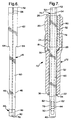
- FIGS. 1 and 2 of the drawings there are shown examples of prior art applications of diesel engine glow plugs to both open chamber and pre-chamber type diesel engines. These applications utilize glow plugs of a common type having a glow tip formed within a metal sheath. However, the use of other forms of glow tips in place of the metal sheath type glow plugs is also known.
- numeral 100 generally indicates an open chamber type diesel engine having a cylinder block 102 defining a cylinder 104 closed by a cylinder head 106.
- a piston 108 is reciprocable in the cylinder 104 and defines a recessed bowl which, together with the cylinder head, forms a combustion chamber 110.
- the cylinder head 106 mounts an injection nozzle or injector 112 which sprays fuel into the combustion chamber 110 for compression ignition therein.
- the cylinder head also mounts a known form of glow plug 114 having a glow tip 116 extending into the combustion chamber. The glow tip is heated during cold engine starting and low temperature operation to assist in igniting fuel sprayed into the combustion chamber during periods when the temperature of compression may be insufficient to provide for proper fuel ignition and combustion.
- the illustrated glow plug 114 is of the type having a metallic sheath forming the glow tip.
- a terminal 118 is provided at the outer end of the glow plug for connection with a source of electric current. Return current flow is from the metal sheath of the glow tip to a metal shell 119 of the glow plug and to the cylinder head in which the shell is mounted and which is grounded to the electrical system.
- numeral 120 indicates a pre-chamber type diesel engine having a cylinder block 122 with a cylinder 124 closed by a cylinder head 126 and carrying a piston 128 reciprocable in the cylinder.
- the piston and cylinder head form a combustion chamber 130 which connects with a pre-combustion chamber or pre-chamber 132 within the cylinder head.
- a fuel injector 134 is mounted in the cylinder head for injecting fuel into the pre-chamber 132.
- a glow plug 136 of known form has a glow tip 138 extending into the pre-chamber to assist in igniting the fuel during starting and cold operation.
- a terminal 140 at the other end of the glow plug provides for connection to a source of electric current and the glow plug shell 142 is grounded to the cylinder head for completing the return current flow path as in the first described embodiment.
- the present invention provides novel glow sensors which may be installed in the glow plug openings of diesel engines of the types previously described. These glow sensors provide both the prior glow plug function of assisting in the ignition of the fuel during cold starting and operation and the additional ion sensor function of sensing the occurrence and character of the combustion event in the combustion chamber or pre-chamber through variations in ionization of combustion gases within the chamber during combustion in accordance with and for purposes that are known in the art.
- the terms "inner end” and “outer end” as used in the subsequent description and claims refer to directions in the glow sensor as installed in an engine wherein the glow tip forms an inner end extending within a combustion chamber (including a pre-chamber) and electrical terminals are located at an outer end extending outside the engine cylinder head.
- glow sensor 10 generally indicates a first embodiment of glow sensor formed in accordance with the invention.
- Glow sensor 10 combines the functions of an ignition glow plug and a combustion chamber ion sensor in a single device having the general appearance of a glow plug and able to be installed in an engine in the cylinder head opening commonly provided for a glow plug.
- glow sensor 10 has a general configuration similar to that of the prior art glow plug 136 shown in FIG. 2; however, the internal features and glow sensor element could equally well be used in glow sensors configured similarly to prior art glow plug 114 shown in FIG. 1.
- Glow sensor 10 is constructed with a tubular metal shell 12 having a hollow interior, into one end of which is inserted a tubular ceramic sleeve 14 that in turn carries a ceramic flat plate glow sensor element 16.
- the metal shell 12 may be made of steel and includes external threads 18 and a hexagonal end 20 for threading the glow sensor into a conventional glow plug opening in the cylinder head of a diesel engine.
- a conical shoulder 22 may be provided for seating the metal shell against a seat in the engine glow plug opening.
- the shell 12 is generally tubular and includes a counterbore 24 opening through an outer end 26 of the shell and terminating internally in a conical seat 28 against which a sealing gasket 30, such as a copper washer or the like, is seated.
- the ceramic sleeve 14 is received within counterbore 24 and has a conical end that engages the sealing gasket 30.
- the outer end 26 of the shell is crimped over to retain the ceramic sleeve 14 in place and exert an axial force thereon which compresses the sealing gasket 30 to provide a combustion seal at the interface.
- the flat plate glow sensor element 16 is supported within the ceramic sleeve 14 and extends through the metal shell 12. Clearances between the element 16 and the sleeve 14 and between the element 16 and the shell 12 are filled with electrical insulation 32 in the form of a glass or ceramic powder or cement seal which provides in addition structural support for the ceramic element 16 to prevent failure due to vibration of the element within the shell and sleeve.
- a metallic washer 34 is welded to an inner end 36 of the shell to retain the electrical insulation surrounding the element 16 within the shell 12.
- the glow sensor element 16 is made up of a ceramic flat plate 38 extending between inner and outer ends 40, 42 respectively of the glow sensor element and having first and second opposite sides 44, 46 respectively and adjacent lateral edges 48.
- an electric heating element 50 is formed on the first side 44 of the plate.
- Element 50 connects with first and second conductors 52, 54, respectively, extending from the ends of the heating element to the outer end 42 of the flat plate 38.
- the heating element 50 is located on the flat plate near its inner end 40 and forms a glow tip at the inner end of the glow sensor element.
- the heating element 50 and the conductors 52, 54 connected with it are preferably formed of platinum (Pt) or palladium (Pd) applied as ink by printing on the first side 44 of the flat plate 38.
- a conductive ink such as platinum or palladium is applied on the second side 46 of the flat plate as shown in FIG. 6.
- the conductive ink is printed adjacent the outer end 40 of the flat plate, forming an exposed ion sensor electrode 56 which is connected by a single conductor 58 with the opposite outer end 42 of the flat plate 38.
- a protective coating of ceramic 60 is applied which covers the heating element and its conductors and the conductor for the ion sensor electrode 56 to protect them from exposure and corrosion by combustion gases.
- the ion sensor electrode 56 is left exposed, as is necessary for its operation and the conductors 52, 54, 58 are exposed at the outer end of the flat plate for connection to separate terminals not shown.
- glow sensor 10 so far described are in general common with those of the second embodiment to be subsequently described. Accordingly like numerals are utilized for like parts. Sensor 10 is unique, however, in the manner in which the glow sensor element is constructed to provide for its retention within the sleeve 14 and shell 12.
- the ceramic flat plate 38 and the resulting glow sensor element 16 are maintained with a generally constant thickness over the entire length of the element.
- the flat plate is provided with lateral edges including an outwardly stepped portion 62 adjacent the outer end 42 of the glow sensor element 16.
- the stepped portion includes angled abutments 64 which engage an internal annular seat 66 formed within the ceramic sleeve 14 and preventing the glow sensor element 16 from moving further inward within the sleeve 14 and the associated metallic shell 12.
- glow sensor 70 is similar in large part to the first described embodiment of glow sensor 10 so that like numerals are used for like parts.
- the construction of glow sensor 70 differs in one respect in that the shell 72 and glow sensor element 74 are made longer for installation of the assembly into a direct injection diesel engine as shown in FIG. 1. However these elements could be formed with a length similar to those of glow sensor 10 for installation within an indirect injection engine as shown in FIG. 2.
- a significant difference in the construction of the second embodiment of glow sensor 70 is that the glow sensor element 74 is modified by the addition of ceramic shoulders or plates 76 laminated onto the first and second sides of the ceramic flat plate 78 and over the ceramic coating 60 which protects the conductors printed on the first and second sides 44, 46 of the plate. These shoulders 76 are received within a recess within the ceramic sleeve 80 and function to retain the glow sensor element 74 from movement further inward from its fixed position within the shell 72.
- This construction allows the flat plate to be simplified by eliminating the stepped portion and providing lateral edges 82 which are linear and can thus be cut from a flat sheet with a single straight cut thereby making manufacture of flat plates for the glow sensor elements more efficient and less costly.
- glow sensor element 70 is essentially the same as that of glow sensor 10.
- combustion chamber is intended to include a pre-chamber or precombustion chamber within its scope.
Landscapes
- Engineering & Computer Science (AREA)
- Chemical & Material Sciences (AREA)
- Combustion & Propulsion (AREA)
- Mechanical Engineering (AREA)
- General Engineering & Computer Science (AREA)
- Ignition Installations For Internal Combustion Engines (AREA)
- Measuring Oxygen Concentration In Cells (AREA)
Applications Claiming Priority (2)
| Application Number | Priority Date | Filing Date | Title |
|---|---|---|---|
| US09/160,397 US6144015A (en) | 1998-09-25 | 1998-09-25 | Glow sensor--ceramic flat plate |
| US160397 | 1998-09-25 |
Publications (3)
| Publication Number | Publication Date |
|---|---|
| EP0989368A2 true EP0989368A2 (fr) | 2000-03-29 |
| EP0989368A3 EP0989368A3 (fr) | 2004-12-01 |
| EP0989368B1 EP0989368B1 (fr) | 2006-08-09 |
Family
ID=22576737
Family Applications (1)
| Application Number | Title | Priority Date | Filing Date |
|---|---|---|---|
| EP99203028A Expired - Lifetime EP0989368B1 (fr) | 1998-09-25 | 1999-09-16 | Capteur d'incandescence sous forme de plaque céramique |
Country Status (3)
| Country | Link |
|---|---|
| US (1) | US6144015A (fr) |
| EP (1) | EP0989368B1 (fr) |
| DE (1) | DE69932685T2 (fr) |
Cited By (2)
| Publication number | Priority date | Publication date | Assignee | Title |
|---|---|---|---|---|
| WO2002002993A1 (fr) * | 2000-06-30 | 2002-01-10 | Robert Bosch Gmbh | Bougie crayon de prechauffage a detecteur de courant ionique et procede pour faire fonctionner une telle bougie |
| WO2019191272A1 (fr) | 2018-03-27 | 2019-10-03 | Scp Holdings, Llc. | Allumeurs pour surface chaude pour plaques de cuisson |
Families Citing this family (13)
| Publication number | Priority date | Publication date | Assignee | Title |
|---|---|---|---|---|
| EP0834652B1 (fr) * | 1996-04-10 | 2004-10-13 | Denso Corporation | Bougie de prechauffage, son procede de fabrication, et detecteur de courant ionique |
| DE19849120C2 (de) * | 1998-10-23 | 2000-09-28 | Beru Ag | Glühkerze |
| US6342690B1 (en) * | 2000-12-01 | 2002-01-29 | O'donnell Steven B. | Glow plug assembly method and construction |
| JP2002299012A (ja) * | 2001-04-02 | 2002-10-11 | Ngk Spark Plug Co Ltd | セラミックヒータ及びその製造方法、グロープラグ及びイオン電流検出装置 |
| JP3816073B2 (ja) * | 2003-01-28 | 2006-08-30 | 日本特殊陶業株式会社 | グロープラグ及びグロープラグの製造方法 |
| US20060163065A1 (en) * | 2005-01-26 | 2006-07-27 | Woodward Governor Company | Ion sensors formed with coatings |
| US20090206069A1 (en) * | 2007-09-23 | 2009-08-20 | Saint-Gobain Ceramics & Plastics, Inc. | Heating element systems |
| US8050848B2 (en) * | 2008-10-24 | 2011-11-01 | Hoerbiger Kompressortechnik Holding Gmbh | Method and system for igniting a lean fuel mixture in a main chamber of an internal combustion engine |
| KR101115006B1 (ko) | 2009-09-01 | 2012-03-06 | 주식회사 유라테크 | 글로우플러그 |
| US10941746B2 (en) * | 2013-03-15 | 2021-03-09 | Alfred Anthony Black | I.C.E., igniter adapted for optional placement of an integral fuel injector in direct fuel injection mode |
| EP2806151A1 (fr) * | 2013-05-20 | 2014-11-26 | Perkins Engines Company Limited | Injecteur à carburant |
| DE102013112806B4 (de) | 2013-11-20 | 2016-06-23 | Borgwarner Ludwigsburg Gmbh | Verfahren zum Herstellen einer Glühkerze |
| JP6144610B2 (ja) * | 2013-12-03 | 2017-06-07 | 京セラ株式会社 | 電極内蔵セラミック体およびこれを用いたヒータ |
Citations (4)
| Publication number | Priority date | Publication date | Assignee | Title |
|---|---|---|---|---|
| US4760830A (en) * | 1981-07-23 | 1988-08-02 | Ambac Industries, Incorporated | Method and apparatus for controlling fuel injection timing in a compression ignition engine |
| DE19737396A1 (de) * | 1996-09-12 | 1998-03-19 | Denso Corp | Glühkerze |
| JPH1089223A (ja) * | 1996-09-11 | 1998-04-07 | Denso Corp | グロープラグ |
| JPH1089687A (ja) * | 1996-09-18 | 1998-04-10 | Denso Corp | グロープラグ |
Family Cites Families (18)
| Publication number | Priority date | Publication date | Assignee | Title |
|---|---|---|---|---|
| US4545339A (en) * | 1982-09-30 | 1985-10-08 | Allied Corporation | Glow plug having a conductive film heater |
| DE3428371A1 (de) * | 1984-08-01 | 1986-02-13 | Robert Bosch Gmbh, 7000 Stuttgart | Verfahren zur messung und regelung von betriebsdaten von verbrennungsmotoren |
| JPS6244971A (ja) * | 1985-08-23 | 1987-02-26 | 日本特殊陶業株式会社 | セラミツク基板ヒ−タ− |
| US4810853A (en) * | 1986-10-28 | 1989-03-07 | Hitachi Metals Ltd. | Glow plug for diesel engines |
| JPH01313362A (ja) * | 1988-06-09 | 1989-12-18 | Ngk Spark Plug Co Ltd | セラミック発熱体およびその製造方法 |
| US5084607A (en) * | 1989-07-28 | 1992-01-28 | Caterpillar Inc. | Interference connection between a heating element and body of a glow plug |
| US5264681A (en) * | 1991-02-14 | 1993-11-23 | Ngk Spark Plug Co., Ltd. | Ceramic heater |
| DE4334771C2 (de) * | 1993-10-12 | 1996-03-28 | Beru Werk Ruprecht Gmbh Co A | Glühkerze |
| DE4335292A1 (de) * | 1993-10-15 | 1995-04-20 | Beru Werk Ruprecht Gmbh Co A | Glühkerze |
| JPH07293417A (ja) * | 1994-04-22 | 1995-11-07 | Isuzu Ceramics Kenkyusho:Kk | 自己温度制御形グロープラグ |
| IT235871Y1 (it) * | 1995-05-31 | 2000-07-18 | Cooper Ind Inc | Guarnizione oscillante e autopulente per una resistenza corazzata diuna candela di pre-riscaldo per motori diesel |
| JPH09105677A (ja) * | 1995-10-12 | 1997-04-22 | Isuzu Ceramics Kenkyusho:Kk | セラミックシース型部品及びその製造方法 |
| EP0834652B1 (fr) * | 1996-04-10 | 2004-10-13 | Denso Corporation | Bougie de prechauffage, son procede de fabrication, et detecteur de courant ionique |
| JP3796846B2 (ja) * | 1996-09-12 | 2006-07-12 | 株式会社デンソー | グロープラグ |
| JP3801756B2 (ja) * | 1996-11-19 | 2006-07-26 | 日本特殊陶業株式会社 | セラミックグロープラグ |
| US5880432A (en) * | 1996-12-23 | 1999-03-09 | Le-Mark International Ltd. | Electric heating device with ceramic heater wedgingly received within a metalic body |
| JPH10332149A (ja) * | 1997-03-31 | 1998-12-15 | Ngk Spark Plug Co Ltd | セラミックヒータ |
| JPH10300085A (ja) * | 1997-04-22 | 1998-11-13 | Ngk Spark Plug Co Ltd | セラミックヒータおよびセラミックグロープラグ |
-
1998
- 1998-09-25 US US09/160,397 patent/US6144015A/en not_active Expired - Lifetime
-
1999
- 1999-09-16 EP EP99203028A patent/EP0989368B1/fr not_active Expired - Lifetime
- 1999-09-16 DE DE69932685T patent/DE69932685T2/de not_active Expired - Lifetime
Patent Citations (4)
| Publication number | Priority date | Publication date | Assignee | Title |
|---|---|---|---|---|
| US4760830A (en) * | 1981-07-23 | 1988-08-02 | Ambac Industries, Incorporated | Method and apparatus for controlling fuel injection timing in a compression ignition engine |
| JPH1089223A (ja) * | 1996-09-11 | 1998-04-07 | Denso Corp | グロープラグ |
| DE19737396A1 (de) * | 1996-09-12 | 1998-03-19 | Denso Corp | Glühkerze |
| JPH1089687A (ja) * | 1996-09-18 | 1998-04-10 | Denso Corp | グロープラグ |
Non-Patent Citations (2)
| Title |
|---|
| PATENT ABSTRACTS OF JAPAN vol. 1998, no. 09, 31 July 1998 (1998-07-31) & JP 10 089223 A (DENSO CORP), 7 April 1998 (1998-04-07) * |
| PATENT ABSTRACTS OF JAPAN vol. 1998, no. 09, 31 July 1998 (1998-07-31) & JP 10 089687 A (DENSO CORP), 10 April 1998 (1998-04-10) * |
Cited By (4)
| Publication number | Priority date | Publication date | Assignee | Title |
|---|---|---|---|---|
| WO2002002993A1 (fr) * | 2000-06-30 | 2002-01-10 | Robert Bosch Gmbh | Bougie crayon de prechauffage a detecteur de courant ionique et procede pour faire fonctionner une telle bougie |
| US6921879B2 (en) | 2000-06-30 | 2005-07-26 | Robert Bosch Gmbh | Sheath type glow plug with ion current sensor and method for operation thereof |
| WO2019191272A1 (fr) | 2018-03-27 | 2019-10-03 | Scp Holdings, Llc. | Allumeurs pour surface chaude pour plaques de cuisson |
| EP3777474A4 (fr) * | 2018-03-27 | 2022-08-10 | SCP Holdings, an Assumed Business Name of Nitride Igniters, LLC. | Allumeurs pour surface chaude pour plaques de cuisson |
Also Published As
| Publication number | Publication date |
|---|---|
| EP0989368B1 (fr) | 2006-08-09 |
| DE69932685T2 (de) | 2007-08-02 |
| US6144015A (en) | 2000-11-07 |
| DE69932685D1 (de) | 2006-09-21 |
| EP0989368A3 (fr) | 2004-12-01 |
Similar Documents
| Publication | Publication Date | Title |
|---|---|---|
| US6144015A (en) | Glow sensor--ceramic flat plate | |
| EP2054617B1 (fr) | Dispositif d'allumage de carburant par décharge haute puissance | |
| US8912716B2 (en) | Copper core combustion cup for pre-chamber spark plug | |
| EP2330702B1 (fr) | Bougie d'allumage | |
| EP0989369B1 (fr) | Combinaison d'élément de moteur et de capteur à incandescence | |
| US6923042B2 (en) | Ignition apparatus for internal combustion engine | |
| US8384278B2 (en) | Leadless package housing having an insulator and composition | |
| EP0989370A2 (fr) | Métal pour extrémité de capteur d'incandescence | |
| US6215105B1 (en) | Ion sensor glow plug assembly with coating between sheath and shell | |
| US20100019643A1 (en) | Sparkplug, in Particular for High Combustion Chamber Pressures | |
| US6148660A (en) | Glow sensor-ceramic tip | |
| JP2001505712A (ja) | 点火プラグ | |
| US4582981A (en) | Glow plug having a resistive surface film heater | |
| JPH0945464A (ja) | グロープラグ | |
| JP3870859B2 (ja) | グロープラグ | |
| JPH05242954A (ja) | 点火プラグおよびその製造方法 | |
| JPH09266056A (ja) | スパークプラグ | |
| JPS60201231A (ja) | 内燃機関の圧力検出器 | |
| AU2013257509B2 (en) | High power discharge fuel ignitor | |
| JPH1187014A (ja) | 層状燃焼方式エンジン用スパークプラグ | |
| WO2001056125A2 (fr) | Bougie longue durée à jet du type plasmatique | |
| JPH09256939A (ja) | 点火プラグ及びその取り付け構造 | |
| JPH04303584A (ja) | 内燃機関用スパークプラグ | |
| JPS61205323A (ja) | デイ−ゼル機関 | |
| JP2000192874A (ja) | 火花点火装置 |
Legal Events
| Date | Code | Title | Description |
|---|---|---|---|
| PUAI | Public reference made under article 153(3) epc to a published international application that has entered the european phase |
Free format text: ORIGINAL CODE: 0009012 |
|
| AK | Designated contracting states |
Kind code of ref document: A2 Designated state(s): AT BE CH CY DE DK ES FI FR GB GR IE IT LI LU MC NL PT SE |
|
| AX | Request for extension of the european patent |
Free format text: AL;LT;LV;MK;RO;SI |
|
| PUAL | Search report despatched |
Free format text: ORIGINAL CODE: 0009013 |
|
| AK | Designated contracting states |
Kind code of ref document: A3 Designated state(s): AT BE CH CY DE DK ES FI FR GB GR IE IT LI LU MC NL PT SE |
|
| AX | Request for extension of the european patent |
Extension state: AL LT LV MK RO SI |
|
| 17P | Request for examination filed |
Effective date: 20050601 |
|
| AKX | Designation fees paid |
Designated state(s): DE FR GB |
|
| GRAP | Despatch of communication of intention to grant a patent |
Free format text: ORIGINAL CODE: EPIDOSNIGR1 |
|
| GRAS | Grant fee paid |
Free format text: ORIGINAL CODE: EPIDOSNIGR3 |
|
| GRAA | (expected) grant |
Free format text: ORIGINAL CODE: 0009210 |
|
| AK | Designated contracting states |
Kind code of ref document: B1 Designated state(s): DE FR GB |
|
| REG | Reference to a national code |
Ref country code: GB Ref legal event code: FG4D |
|
| REF | Corresponds to: |
Ref document number: 69932685 Country of ref document: DE Date of ref document: 20060921 Kind code of ref document: P |
|
| EN | Fr: translation not filed | ||
| PLBE | No opposition filed within time limit |
Free format text: ORIGINAL CODE: 0009261 |
|
| STAA | Information on the status of an ep patent application or granted ep patent |
Free format text: STATUS: NO OPPOSITION FILED WITHIN TIME LIMIT |
|
| 26N | No opposition filed |
Effective date: 20070510 |
|
| GBPC | Gb: european patent ceased through non-payment of renewal fee |
Effective date: 20061109 |
|
| PG25 | Lapsed in a contracting state [announced via postgrant information from national office to epo] |
Ref country code: GB Free format text: LAPSE BECAUSE OF NON-PAYMENT OF DUE FEES Effective date: 20061109 |
|
| PG25 | Lapsed in a contracting state [announced via postgrant information from national office to epo] |
Ref country code: FR Free format text: LAPSE BECAUSE OF FAILURE TO SUBMIT A TRANSLATION OF THE DESCRIPTION OR TO PAY THE FEE WITHIN THE PRESCRIBED TIME-LIMIT Effective date: 20070511 |
|
| PG25 | Lapsed in a contracting state [announced via postgrant information from national office to epo] |
Ref country code: FR Free format text: LAPSE BECAUSE OF FAILURE TO SUBMIT A TRANSLATION OF THE DESCRIPTION OR TO PAY THE FEE WITHIN THE PRESCRIBED TIME-LIMIT Effective date: 20060809 |
|
| PGFP | Annual fee paid to national office [announced via postgrant information from national office to epo] |
Ref country code: DE Payment date: 20100908 Year of fee payment: 12 |
|
| REG | Reference to a national code |
Ref country code: DE Ref legal event code: R119 Ref document number: 69932685 Country of ref document: DE Effective date: 20130403 |
|
| PG25 | Lapsed in a contracting state [announced via postgrant information from national office to epo] |
Ref country code: DE Free format text: LAPSE BECAUSE OF NON-PAYMENT OF DUE FEES Effective date: 20130403 |