EP0989248A2 - Einrichtung zur sperre des Wasserablaufes eines Leichtflüssigkeitsabscheiders - Google Patents
Einrichtung zur sperre des Wasserablaufes eines Leichtflüssigkeitsabscheiders Download PDFInfo
- Publication number
- EP0989248A2 EP0989248A2 EP99118392A EP99118392A EP0989248A2 EP 0989248 A2 EP0989248 A2 EP 0989248A2 EP 99118392 A EP99118392 A EP 99118392A EP 99118392 A EP99118392 A EP 99118392A EP 0989248 A2 EP0989248 A2 EP 0989248A2
- Authority
- EP
- European Patent Office
- Prior art keywords
- float
- locking element
- drain pipe
- light liquid
- water
- Prior art date
- Legal status (The legal status is an assumption and is not a legal conclusion. Google has not performed a legal analysis and makes no representation as to the accuracy of the status listed.)
- Withdrawn
Links
- 239000007788 liquid Substances 0.000 title claims description 22
- 230000004888 barrier function Effects 0.000 title 1
- XLYOFNOQVPJJNP-UHFFFAOYSA-N water Substances O XLYOFNOQVPJJNP-UHFFFAOYSA-N 0.000 claims description 24
- 230000000903 blocking effect Effects 0.000 claims description 7
- 238000009434 installation Methods 0.000 claims description 4
- 239000012858 resilient material Substances 0.000 claims 1
- 238000007789 sealing Methods 0.000 claims 1
- 238000000926 separation method Methods 0.000 description 6
- 230000002706 hydrostatic effect Effects 0.000 description 2
- 238000004140 cleaning Methods 0.000 description 1
- 238000007689 inspection Methods 0.000 description 1
- 238000000034 method Methods 0.000 description 1
- 230000000630 rising effect Effects 0.000 description 1
- 239000002351 wastewater Substances 0.000 description 1
Images
Classifications
-
- B—PERFORMING OPERATIONS; TRANSPORTING
- B01—PHYSICAL OR CHEMICAL PROCESSES OR APPARATUS IN GENERAL
- B01D—SEPARATION
- B01D17/00—Separation of liquids, not provided for elsewhere, e.g. by thermal diffusion
- B01D17/02—Separation of non-miscible liquids
- B01D17/0208—Separation of non-miscible liquids by sedimentation
- B01D17/0214—Separation of non-miscible liquids by sedimentation with removal of one of the phases
Definitions
- the invention relates to a device for blocking the drainage of a Light liquid separator, with a water inlet opening at the bottom of one Drain pipe, with a float arranged next to the drain pipe and with a locking element connected to the float, which is below the Water inlet opening is arranged and this closes when a maximum Thickness of the light liquid layer is reached.
- a light liquid separator with such a device is, for example DE 297 08 916 U can be found.
- the closure body is also by a The float is formed over a linkage from the one following the water level Float is held in the open position. As soon as the water level on the the intended minimum has dropped, the linkage releases the closure body rises up and closes the drain opening.
- an operating rod provided that acts directly on the closure body.
- the inlet opening that is open at the top in a drain pipe horizontal section means by a double redirection of the wastewater 90 ° each an additional flow resistance until the water in the drain pipe reached. This can affect the functionality, for example through a earlier drain backflow, by reducing the Light liquid separation section between inlet and outlet, etc.
- the invention has therefore set itself the task of one Light liquid separator with a water inlet opening at the lower end of a Riser to form a closure positively guided by the float.
- this is achieved in that a two-armed on the drain pipe Lever arrangement is provided on which the float and the locking element are arranged.
- the float and the locking element on the drain pipe are thus oppositely forced, i.e. the float sinks to the water level following, the locking element is raised until the opening is closed.
- the two-armed lever arrangement has two levers articulated parallel to each other on the drain riser, between the float is arranged at its first ends and at its second ends connecting rods extending essentially vertically downwards are articulated, on which the locking element is arranged.
- the float and the blocking element can also be deflected Cable or the like be connected.
- a preferred embodiment sees one Closing position release device in front of the swimmer Release element and one in an upper one, for example via an opening in the separation basin
- Accessible handle has a pull rope.
- the pull rope is preferred by the space between the float and the Run-down pipe passed through, a cross bar or the like as a release element. that hangs freely down to the lowest float position and that Gap cannot happen. If the release element is pulled up, it attaches to the float, which swings up on the two levers, the Push the connecting rods down the locking element. If an extension of the vertical drain pipe above the lateral drain pipe is, for example for inspection and cleaning purposes, there is also an alternative Opening of the locking element through an inserted through the drain pipe Push rod or the like
- a mounting lock can be provided, which Locking element holds in its open position, and releases as soon as the float from rising water is raised.
- the assembly lock has, for example One hook per lever on the drain pipe and one on a rope mounted eyelet, which is hooked into the hook, the rope in Area of the connecting rods is fixed to the lever.
- Another preferred embodiment sees the device in an assembly-ready Installation housing in front, for example on a wall of the separation basin is mountable, each water-permeable side wall having a filter layer.
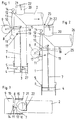
- FIG. 1 shows a side view of the device according to the invention in the open State
- Fig. 2 in the closed state
- Fig. 3 is a plan view of the 2
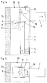
- FIG. 4 is a side view of the with an installation housing 1
- FIG. 5 is a plan view according to FIG. 3.
- a device is for blocking the water drain from one Light liquid separation basin provided if, as can be seen from Fig. 2, the Thickness of the light liquid layer 26 reaches a level that the water surface 25 has lowered to a minimum height below which the function of the Light liquid separation is questioned, and at the latest the Light liquid must be removed.
- the facility includes a vertical one Drain pipe 1 with subsequent drain pipe 2, which is the maximum height of Water surface 25 specifies (Fig. 1).
- the downwardly open inlet opening 3 of the drain pipe 1 is below the minimal water surface 25, so that in each case only water in the Drain pipe 1 can flow (arrows 27).
- a seal 6 provided locking element 4 is provided below the inlet opening 3 .
- tabs 5 are arranged, which protrude downwards and that Guide the underlying locking element 4 on the circumference.
- the locking element 4 is on two connecting rods 7 hinged to the outside of the drain pipe 1 after guided above and at the second ends of two levers 10 of a two-armed Lever arrangement are articulated.
- the two mutually parallel levers 10 are around Axles 8 pivotally mounted on a holding part mounted on the drain pipe 1 15 are arranged, and carry a float 9 between the first ends. Because of this arrangement, the locking element 4 when the float drops 9 from the normal position of FIG. 1 to the minimum position of FIG. 2 and closes the inlet opening 3.
- a hook 17 is provided on the drain pipe 1, in which one a rope or chain 18 mounted eyelet 19 is suspended, as shown in Fig. 1.
- the float 9 floats when the separator is filled for the first time, hooks occur the eye 19 from the hook 17 and the arm connected to the rope 18 of the Lever 10 is released. This happens automatically because the hook 17 relative to Lever 10 is offset from the vertical.
- the Device is therefore provided with a closing position release device, which is below the Float 9 freely arranged release element 11 and a between the float 9th and the drain pipe 1 through an upper tab 12 and up with a handle 14 provided rope 13.
- the release element 11 is formed for example as a crossbar, and larger than the gap between the Float 9 and the drain riser 1. This engages under the release element 11 Float 9 only when pulling up, with the locking element 4 pressed down becomes.
- the drain pipe 1 has an upper nozzle 20, which is connected by a with a Lock 22 provided lid 21 is closed.
- the locking element 4 could therefore after opening the cover 21 or down through a rod or the like are pressed so that neither the assembly lock 17, 18, 19 nor the Closing position release device 11, 12, 13, 14 are absolutely necessary.
- FIGS. 4 and 5 schematically show one arranged in a built-in housing 23 Device for blocking the water drain, which with a on the wall of the Separation tank fixable mounting plate 28 or the like is provided. At least one The side wall of the housing 23 must be permeable to water and is a filter 24 educated.
Landscapes
- Physics & Mathematics (AREA)
- Thermal Sciences (AREA)
- Chemical & Material Sciences (AREA)
- Chemical Kinetics & Catalysis (AREA)
- Filtration Of Liquid (AREA)
- Sink And Installation For Waste Water (AREA)
- Removal Of Floating Material (AREA)
Abstract
Description
Claims (9)
- Einrichtung zur Sperre des Wasserablaufes eines Leichtflüssigkeitsabscheiders, mit einer Wassereintrittsöffnung (3) am unteren Ende eines Ablaufsteigrohres (1), mit einem neben dem Ablaufsteigrohr (1) angeordneten Schwimmer (9) und mit einem mit dem Schwimmer (9) verbundenen Sperrelement (4), das unterhalb der Wassereintrittsöffnung (3) angeordnet ist und diese verschließt, wenn eine maximale Dicke der Leichtflüssigkeitsschicht (26) erreicht ist, dadurch gekennzeichnet, daß am Ablaufsteigrohr (1) eine zweiarmige Hebelanordnung vorgesehen ist, an der der Schwimmer (9) und das Sperrelement (4) angeordnet sind.
- Einrichtung nach Anspruch 1, dadurch gekennzeichnet, daß die zweiarmige Hebelanordnung zwei am Ablaufsteigrohr (1) zueinander parallel angelenkte Hebel (10) aufweist, zwischen deren ersten Enden der Schwimmer (9) angeordnet ist, und an deren zweiten Enden sich im wesentlichen vertikal nach unten erstreckende Verbindungsstangen (7) angelenkt sind, an denen das Sperrelement (4) angeordnet ist.
- Einrichtung nach Anspruch 2, dadurch gekennzeichnet, daß das Sperrelement (4) an vom Umfang des Ablaufsteigrohres (1) nach unten abstehenden Laschen (5) geführt ist.
- Einrichtung nach einem der Ansprüche 1 bis 3, dadurch gekennzeichnet, daß die Oberseite des Sperrelementes (4) zumindest im Randbereich mit einem Dichtstreifen (6) aus einem elastisch nachgiebigen Material versehen ist.
- Einrichtung nach einem der Ansprüche 1 bis 4, dadurch gekennzeichnet, daß dem Sperrelement (4) eine Schließstellungslöseeinrichtung zugeordnet ist, die ein den Schwimmer untergreifendes Löseelement (11) und ein in einem oberen Handgriff (14) endendes Zugseil (13) aufweist.
- Einrichtung nach Anspruch 5, dadurch gekennzeichnet, daß das Löseelement (11) durch einen Querstab gebildet ist, und das Zugseil (13) zwischen den zueinander parallelen Hebeln (10) hindurch geführt ist.
- Einrichtung nach einem der Ansprüche 1 bis 6, dadurch gekennzeichnet, daß zumindest einem der beiden Hebel (10) eine Montageverriegelung zugeordnet ist, die sich bei der Erstflutung des Leichtflüssigkeitsabscheiders selbsttätig löst.
- Einrichtung nach Anspruch 7, dadurch gekennzeichnet, daß die Montageverriegelung pro Hebel (10) einen am Ablaufsteigrohr (1) unterhalb des Hebels (10) angeordneten Haken (17) und eine an einem Seil (18) montierte Öse (19) aufweist, wobei das Seil (18) im Bereich der Verbindungsstangen (7) am Hebelarm (10) fixiert ist.
- Einrichtung nach einem der Ansprüche 1 bis 8, dadurch gekennzeichnet, daß sie in einem Einbaugehäuse (23) angeordnet ist, in dem jede wasserdurchlässige Seitenwand eine Filterschicht (24) aufweist.
Applications Claiming Priority (2)
| Application Number | Priority Date | Filing Date | Title |
|---|---|---|---|
| AT158898 | 1998-09-23 | ||
| AT158898A AT407538B (de) | 1998-09-23 | 1998-09-23 | Einrichtung zur sperre des wasserablaufes eines leichtflüssigkeitsabscheiders |
Publications (2)
| Publication Number | Publication Date |
|---|---|
| EP0989248A2 true EP0989248A2 (de) | 2000-03-29 |
| EP0989248A3 EP0989248A3 (de) | 2002-04-17 |
Family
ID=3516677
Family Applications (1)
| Application Number | Title | Priority Date | Filing Date |
|---|---|---|---|
| EP99118392A Withdrawn EP0989248A3 (de) | 1998-09-23 | 1999-09-16 | Einrichtung zur sperre des Wasserablaufes eines Leichtflüssigkeitsabscheiders |
Country Status (2)
| Country | Link |
|---|---|
| EP (1) | EP0989248A3 (de) |
| AT (1) | AT407538B (de) |
Families Citing this family (1)
| Publication number | Priority date | Publication date | Assignee | Title |
|---|---|---|---|---|
| AT412410B (de) | 2003-07-04 | 2005-02-25 | Heinrich Ortner | Einrichtung zur sperre des wasserablaufes eines leichtflüssigkeitsabscheiders |
Citations (3)
| Publication number | Priority date | Publication date | Assignee | Title |
|---|---|---|---|---|
| DE520773C (de) | 1928-09-29 | 1931-03-14 | Otto Herberger | Schwimmerabsperrventil fuer das Ablaufrohr eines Leichtfluessigkeitsabscheiders |
| US4132238A (en) | 1977-04-29 | 1979-01-02 | Clark Earl A | Automatic separator valve |
| DE29708916U1 (de) | 1996-05-22 | 1997-08-07 | AUTECH Abwasser-Umwelttechnik GmbH, 90451 Nürnberg | Leichtflüssigkeitsabscheider |
Family Cites Families (9)
| Publication number | Priority date | Publication date | Assignee | Title |
|---|---|---|---|---|
| US1082730A (en) * | 1912-08-23 | 1913-12-30 | Samuel G Brown | Drain-trap. |
| GB450322A (en) * | 1935-01-29 | 1936-07-15 | Alfred John Vaughan | Improvements in devices for separating liquids of different gravity |
| DE2630203C2 (de) * | 1976-07-05 | 1978-09-07 | Passavant-Werke Michelbacher Huette, 6209 Aarbergen | Ablauf mit Rückstauverschluß |
| DE2838559A1 (de) * | 1978-09-04 | 1980-03-20 | Buderus Ag | Leichtfluessigkeitsabscheider |
| NL9201499A (nl) * | 1992-08-24 | 1994-03-16 | Lemacon Techniek Bv | Werkwijze en inrichting voor het afscheiden van een verontreinigde bovenlaag. |
| DE4306807C2 (de) * | 1993-03-04 | 1996-07-11 | Kordes Klaeranlagen U Pumpwerk | Leichtflüssigkeitsabscheider mit umrüstbarer Bodenplatte |
| DE9419621U1 (de) * | 1993-12-08 | 1995-03-16 | Bertsch, Bernhard, 90513 Zirndorf | Leichtflüssigkeitsabscheider |
| DE19636771A1 (de) * | 1996-09-10 | 1998-03-12 | Kaesch Trenntechnik Gmbh | Anlage zur Abscheidung von Leichtflüssigkeiten von mit solchen Flüssigkeiten versetztem Wasser |
| DE29911083U1 (de) * | 1999-06-25 | 1999-09-09 | Passavant-Werke Ag, 65326 Aarbergen | Leichtflüssigkeitsabscheider |
-
1998
- 1998-09-23 AT AT158898A patent/AT407538B/de not_active IP Right Cessation
-
1999
- 1999-09-16 EP EP99118392A patent/EP0989248A3/de not_active Withdrawn
Patent Citations (3)
| Publication number | Priority date | Publication date | Assignee | Title |
|---|---|---|---|---|
| DE520773C (de) | 1928-09-29 | 1931-03-14 | Otto Herberger | Schwimmerabsperrventil fuer das Ablaufrohr eines Leichtfluessigkeitsabscheiders |
| US4132238A (en) | 1977-04-29 | 1979-01-02 | Clark Earl A | Automatic separator valve |
| DE29708916U1 (de) | 1996-05-22 | 1997-08-07 | AUTECH Abwasser-Umwelttechnik GmbH, 90451 Nürnberg | Leichtflüssigkeitsabscheider |
Also Published As
| Publication number | Publication date |
|---|---|
| AT407538B (de) | 2001-04-25 |
| EP0989248A3 (de) | 2002-04-17 |
| ATA158898A (de) | 2000-08-15 |
Similar Documents
| Publication | Publication Date | Title |
|---|---|---|
| DE69918134T2 (de) | Gerät zur verhinderung von rückfluss bei entwässerung | |
| DE202009010367U1 (de) | Vorrichtung zur Trennung von Regenwasser von chemisch, biologisch und/oder toxisch belasteten Abwässern | |
| DE69704569T2 (de) | Anlage zum dränieren von flüssigkeitsbehältern | |
| DE3702482C2 (de) | ||
| EP0368084B1 (de) | Leichtflüssigkeitsabscheider | |
| EP0989248A2 (de) | Einrichtung zur sperre des Wasserablaufes eines Leichtflüssigkeitsabscheiders | |
| EP0979668B1 (de) | Klarwasserabzug | |
| EP3455421B1 (de) | Ablaufventil für einen spülkasten und spülkasten mit ablaufventil | |
| AT412410B (de) | Einrichtung zur sperre des wasserablaufes eines leichtflüssigkeitsabscheiders | |
| EP1127988B1 (de) | Bodenablauf mit Schwimmerverschluss | |
| DE202012006401U1 (de) | Kanalspüler zur Reinigung eines Ablaufkanals für Regen- oder Mischwasser in einem Spülschacht | |
| DE3822555C2 (de) | ||
| DE2630203C2 (de) | Ablauf mit Rückstauverschluß | |
| EP0293513A1 (de) | Verfahren zum Betätigen des Schliessmechanismusses einer schwimmergesteuerten Absperrklappe einer Spülkammer zum Spülen eines Flüssigkeitsspeicherraumes sowie Vorrichtung zur Durchführung des Verfahrens | |
| DE102019122938B4 (de) | Klärüberlauf und Durchlaufbecken | |
| DE10311402B4 (de) | Dekanter | |
| AT405065B (de) | Einrichtung zur sperre eines zulaufes in einem leichtflüssigkeitsabscheider | |
| EP0943741A2 (de) | Ablaufgarnitur für Sanitärausstattungsgegenstände, insbesondere Bade- und Duschwannen | |
| DE2337853C2 (de) | Rückstau- und Geruchsverschluß für Flüssigkelten, Insbesondere Abwässer | |
| EP1580338B1 (de) | Ablaufarmatur für einen Spülkasten | |
| DE2848498A1 (de) | Inspektionskammer-anordnung | |
| DE531794C (de) | Selbsttaetige Durchflusssperre fuer Leichtfluessigkeitsabscheider | |
| DE202020003298U1 (de) | Wasserablaufeinrichtung | |
| DE525373C (de) | Durchflusssperre fuer Leichtfluessigkeitsabscheider | |
| EP0671966B1 (de) | Leichtflüssigkeitsabzugvorrichtung zum einbau in ein abscheidebecken |
Legal Events
| Date | Code | Title | Description |
|---|---|---|---|
| PUAI | Public reference made under article 153(3) epc to a published international application that has entered the european phase |
Free format text: ORIGINAL CODE: 0009012 |
|
| AK | Designated contracting states |
Kind code of ref document: A2 Designated state(s): AT BE CH CY DE DK ES FI FR GB GR IE IT LI LU MC NL PT SE Kind code of ref document: A2 Designated state(s): DE ES FR GB IE IT |
|
| AX | Request for extension of the european patent |
Free format text: AL;LT;LV;MK;RO;SI |
|
| PUAL | Search report despatched |
Free format text: ORIGINAL CODE: 0009013 |
|
| AK | Designated contracting states |
Kind code of ref document: A3 Designated state(s): AT BE CH CY DE DK ES FI FR GB GR IE IT LI LU MC NL PT SE |
|
| AX | Request for extension of the european patent |
Free format text: AL;LT;LV;MK;RO;SI |
|
| 17P | Request for examination filed |
Effective date: 20020905 |
|
| 17Q | First examination report despatched |
Effective date: 20021011 |
|
| AKX | Designation fees paid |
Free format text: DE ES FR GB IE IT |
|
| AXX | Extension fees paid |
Free format text: SI PAYMENT 20020905 |
|
| STAA | Information on the status of an ep patent application or granted ep patent |
Free format text: STATUS: THE APPLICATION IS DEEMED TO BE WITHDRAWN |
|
| 18D | Application deemed to be withdrawn |
Effective date: 20030222 |