EP0989061B1 - Verfahren zum Einbringen von Gefachteilungen in Kästen für sechs oder zwölf Flaschen, Maschine und Gefachteilung dafür - Google Patents
Verfahren zum Einbringen von Gefachteilungen in Kästen für sechs oder zwölf Flaschen, Maschine und Gefachteilung dafür Download PDFInfo
- Publication number
- EP0989061B1 EP0989061B1 EP99402317A EP99402317A EP0989061B1 EP 0989061 B1 EP0989061 B1 EP 0989061B1 EP 99402317 A EP99402317 A EP 99402317A EP 99402317 A EP99402317 A EP 99402317A EP 0989061 B1 EP0989061 B1 EP 0989061B1
- Authority
- EP
- European Patent Office
- Prior art keywords
- box
- equal
- conveyor
- partition
- bottle
- Prior art date
- Legal status (The legal status is an assumption and is not a legal conclusion. Google has not performed a legal analysis and makes no representation as to the accuracy of the status listed.)
- Expired - Lifetime
Links
Images


Classifications
-
- B—PERFORMING OPERATIONS; TRANSPORTING
- B65—CONVEYING; PACKING; STORING; HANDLING THIN OR FILAMENTARY MATERIAL
- B65B—MACHINES, APPARATUS OR DEVICES FOR, OR METHODS OF, PACKAGING ARTICLES OR MATERIALS; UNPACKING
- B65B61/00—Auxiliary devices, not otherwise provided for, for operating on sheets, blanks, webs, binding material, containers or packages
- B65B61/20—Auxiliary devices, not otherwise provided for, for operating on sheets, blanks, webs, binding material, containers or packages for adding cards, coupons or other inserts to package contents
- B65B61/207—Auxiliary devices, not otherwise provided for, for operating on sheets, blanks, webs, binding material, containers or packages for adding cards, coupons or other inserts to package contents for inserting partitions between package contents
-
- B—PERFORMING OPERATIONS; TRANSPORTING
- B31—MAKING ARTICLES OF PAPER, CARDBOARD OR MATERIAL WORKED IN A MANNER ANALOGOUS TO PAPER; WORKING PAPER, CARDBOARD OR MATERIAL WORKED IN A MANNER ANALOGOUS TO PAPER
- B31B—MAKING CONTAINERS OF PAPER, CARDBOARD OR MATERIAL WORKED IN A MANNER ANALOGOUS TO PAPER
- B31B50/00—Making rigid or semi-rigid containers, e.g. boxes or cartons
- B31B50/74—Auxiliary operations
- B31B50/81—Forming or attaching accessories, e.g. opening devices, closures or tear strings
-
- B—PERFORMING OPERATIONS; TRANSPORTING
- B31—MAKING ARTICLES OF PAPER, CARDBOARD OR MATERIAL WORKED IN A MANNER ANALOGOUS TO PAPER; WORKING PAPER, CARDBOARD OR MATERIAL WORKED IN A MANNER ANALOGOUS TO PAPER
- B31D—MAKING ARTICLES OF PAPER, CARDBOARD OR MATERIAL WORKED IN A MANNER ANALOGOUS TO PAPER, NOT PROVIDED FOR IN SUBCLASSES B31B OR B31C
- B31D5/00—Multiple-step processes for making three-dimensional [3D] articles
- B31D5/0004—Multiple-step processes for making three-dimensional [3D] articles for making inserts, e.g. partitions, for boxes
- B31D5/0013—Multiple-step processes for making three-dimensional [3D] articles for making inserts, e.g. partitions, for boxes the inserts having interengaged slotted panels
-
- B—PERFORMING OPERATIONS; TRANSPORTING
- B65—CONVEYING; PACKING; STORING; HANDLING THIN OR FILAMENTARY MATERIAL
- B65D—CONTAINERS FOR STORAGE OR TRANSPORT OF ARTICLES OR MATERIALS, e.g. BAGS, BARRELS, BOTTLES, BOXES, CANS, CARTONS, CRATES, DRUMS, JARS, TANKS, HOPPERS, FORWARDING CONTAINERS; ACCESSORIES, CLOSURES, OR FITTINGS THEREFOR; PACKAGING ELEMENTS; PACKAGES
- B65D5/00—Rigid or semi-rigid containers of polygonal cross-section, e.g. boxes, cartons or trays, formed by folding or erecting one or more blanks made of paper
- B65D5/42—Details of containers or of foldable or erectable container blanks
- B65D5/44—Integral, inserted or attached portions forming internal or external fittings
- B65D5/48—Partitions
- B65D5/48024—Partitions inserted
- B65D5/48026—Squaring or like elements, e.g. honeycomb element, i.e. at least four not aligned compartments
- B65D5/48032—Squaring or like elements, e.g. honeycomb element, i.e. at least four not aligned compartments made of paper, provided with an at least partial bottom
-
- B—PERFORMING OPERATIONS; TRANSPORTING
- B31—MAKING ARTICLES OF PAPER, CARDBOARD OR MATERIAL WORKED IN A MANNER ANALOGOUS TO PAPER; WORKING PAPER, CARDBOARD OR MATERIAL WORKED IN A MANNER ANALOGOUS TO PAPER
- B31B—MAKING CONTAINERS OF PAPER, CARDBOARD OR MATERIAL WORKED IN A MANNER ANALOGOUS TO PAPER
- B31B2105/00—Rigid or semi-rigid containers made by assembling separate sheets, blanks or webs
-
- B—PERFORMING OPERATIONS; TRANSPORTING
- B31—MAKING ARTICLES OF PAPER, CARDBOARD OR MATERIAL WORKED IN A MANNER ANALOGOUS TO PAPER; WORKING PAPER, CARDBOARD OR MATERIAL WORKED IN A MANNER ANALOGOUS TO PAPER
- B31B—MAKING CONTAINERS OF PAPER, CARDBOARD OR MATERIAL WORKED IN A MANNER ANALOGOUS TO PAPER
- B31B2120/00—Construction of rigid or semi-rigid containers
- B31B2120/20—Construction of rigid or semi-rigid containers provided with two or more compartments
- B31B2120/25—Construction of rigid or semi-rigid containers provided with two or more compartments formed by partitions or like inserts not integral with walls
Definitions
- the present invention relates to several methods of internal crisscrossing of corrugated boxes or similar mounted bottom glued for packing six or twelve bottles.
- the invention also relates to machines implementing said methods as well as braces particularly adapted to such machines.
- bottles and especially bottles of wine is made very widely today in a batch of six or twelve bottles that we must, therefore, pack very correctly in crates usually cardboard corrugated or the like having two rows of three bottles for crates of six and three rows of four bottles for cases of twelve. Bottles are placed in these cases by means of casters which must, most of the time, operate at a high rate.
- bottles that are arranged in each box following the two directions must must be rigged to avoid any contact between two successive bottles in one direction or the perpendicular direction.
- the height of the blades can be variable, but always between a maximum value corresponding to the height of the box outside the upper flaps and a minimum height corresponding to the setting of the bodies of bottles, thereby protecting the labels against friction due to to transport. This minimum height will be called later: " protected height " of the bottle.
- corrugated boxes for example example the American funds likely to receive six or twelve bottles, are mounted on formers and before being filled at the packing station, lockers six or twelve bottles are placed inside the same cases.
- This intermediate operation crisscrossing is therefore very important because it must be performed in the rates required by the line bottling. This result is hardly achieved except to use very cumbersome equipment, which comes up in final to limit the cadences on the same area case packing.
- crates appear under the insertion head of the crisscrossing in such a way that their lead over the conveyor is done according to the direction of their largest length in order to obtain maximum stability in their transport; on the other hand, we can see that the insertion vertical blades to form the cross on this type of crates requires storage magazines necessarily on one side or the other of the line of conveying, which usually requires two female drivers for the cruiser. To mitigate all these disadvantages, it is here proposed to take out the boxes of the shaper according to their smallest dimension, ensuring their stability by accumulating them against each other on the conveyor.
- the process according to the invention provides the decisive advantage of an increase of more than thirty per cent of the editing / editing rates in configuration six bottles, resulting from the same position crates which, in the process, advance on the conveyor according to their width, whereas classically we have the same boxes along their longitudinal axis in the axis of the conveyor to prevent their tipping in the operation; according to the method, the crates at the output of the former arrive on the conveyor against each other and parade tight, providing self-hold on the conveyor.
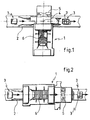
- the crisscrossers 1 of the prior art are conventionally arranged transversely to the axis of the conveyor 2 carrying the boxes 3 previously formed on a formeuse of crates (not shown).
- checkout 3 for six bottles is arranged on the conveyor 2 in out of formeuse and upstream of the cruiser 1, in such a way that its longitudinal axis coincides with the direction of advancement of the conveyor 2.
- the box 3 reaches then at point 4 under the insertion organ of the crisscrosser 1 where join a double element 5 extracted from a specific store and central blades 6 taken from a store located opposite the crisscross to gradually form a bin 7 which will then be inserted in box 3 still waiting at point 4, then moved so equipped by the conveyor 2 up to the bottle packer (not shown on the figure).
- Double element 5 and Blade 6 stores are located both sides of the conveyor line of the boxes 3, requiring monitoring of the cruiser 1 by minus two people; on the other hand, we see that the crisscrosser 1, located transversely to the packing lines, just impede the aisles between several parallel lines of case packer.
- the caster 1 is rotated 90 ° to arrange it in bridge longitudinal axis along the axis of the conveyor 2.
- the boxes mounted 3 at the output of the formeuse arrive on the conveyor 2 front face perpendicular to the direction of progress, corresponding to the length of the box, that is to say at 90 ° with respect to the diagram of FIG.
- FIGS. 3 it will now be described training and packing a locker 7 for six bottles already used in the prior art, especially on the cruiser of Figure 1, for example a cruiser of the Swiss manufacturer RODA.
- Locker 7 indifferently called after brace, is obtained by the combination of a blade 10, said central blade, with a double element 11 stored flat in a cruiser shop as depicted in top view in Figure 3b;
- the double element 11 comprises two identical wings 12 and 12 'made of corrugated cardboard and articulated head-to-tail at a flat bottom normally rectangular 13 thanks to two lines of folding 14, 14 ', parallel to each other and distant one on the other a value of a bottle diameter.
- Each cutout 15, 15 'issuing from the fold line 14, 14' of the corresponding wing extends in the median axis of each wing to a height sufficient for folding each wing 12,12 'according to the arrows P and Q of the figures 3d and 3e, the central blade 10 comes embedded therein precisely until the upper parts not cut-offs come into abutment on shoulders 16,16 ' provided for this purpose on the upper part of the blade 10, as shown in Figure 3e.
- the wings 12,12 ' have a height maximum equal to the height of the boxes as shown in Figure 3f; the width of the wings 12,12 'to their upper end is equal to about twice the diameter of the bottles as shown in Figure 3g; cut sides are advantageously provided on the part lower of the same wings up to their line of connection with the bottom 13 to reduce consumption cardboard and the weight of the spider; however, the length of the bottom 13, that is to say the length of the lines of folding 14,14 'is sufficient to ensure the rigidity of double element 11.
- the blade 10 is then lowered vertically V downwardly to come gradually bearing on the bottom 13 of the element 11, side rollers contributing to raise P and Q (Figure 3d) the wings 12,12 'of the element 11 around the folding lines 14,14 'which gradually surround the blade 10 having cut edges 17 at all its corners to facilitate the rotational movement of said wings which then abut on cuts 16,16' in position vertical parallel, according to Figure 3e; the downward movement along V brings the mounted assembly to the box 3 positioned on the conveyor 2 in line with the insertion head of the cruiser, such that the locker 7 comes exactly inside. of the box 3, as shown in plan view in Figure 3g.
- FIGS. 4-7 it will now be discloses a first method embodying the invention particularly intended for crisscrossing a crate for twelve bottles; such a process is remarkable in what, at a first station 20 ( Figure 6), is inserted into the box 3 a blade 21 (FIG. 4) parallel or substantially parallel to the front face 23 which is perpendicular to the direction of advancement of the conveyor 2, said blade 21 coming to be inserted between two support zones 22,22 'facing the two lateral faces 23,23 'of the box 3 to separate the latter in two substantially equal volumes 24,25; then we advance the box 3 on the conveyor 2 to a second station 26 where we form and insert a first bin 7 of six bottles, as described above in reference to FIG.
- the central blade 21 is arranged to pivot between its support zones 22, 22 'on the two lateral faces of the body 3; in this respect, blade 21, normally rectangular whose height and width correspond to the height and width of the box 3, is cut in accordance with the drawings of the FIG.
- the blade 21 is introduced at the first station 20 in a slightly inclined manner from top to bottom and back to front, to provide a Flared entry at the first volume 25 of the cashier 3 ( Figure 5), to facilitate the introduction of the first rack 7 which straightens the blade 21 by rotation on its supports 22,22 ', in order to clear the entrance of the second volume 24 and allow the insertion of the second bin 7.
- Figure 7 clearly shows one of the advantages of a such a process since a single operator 27 can driving both the box-formter 28 and the cruiser 1, given their proximity and their relative provision, as has already been said.
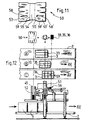
- this process is remarkable in that the body 3 being positioned directly above the head vertical insertion 51 of the cruiser, it forms first a cross twelve bottles from a double element 50, stored flat then extracted from a first store 52, having, when mounted, the general shape a U-shaped channel of the same type as in the variants previous and having two vertical wings 53,53 ' advantageously identical and articulated head-to-tail at a flat bottom 54 following two fold lines 55,55 ' normally distant from a bottle diameter, width normally equal to four times the diameter of a bottle and height at least equal to the height protected bottles and at most equal to the height of crates without flaps, across which according to the diagram A of FIG.
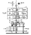
- FIG. 13 there will be finally described a fourth variant of the method implementing the invention for the normally regular crisscrossing of a box 3 twelve bottles.
- the cruiser has only one insertion station 51 to form the braces and insert them inside the crates.
- a first spider 7 for six bottles is first formed, in exactly the same way as in the first variant of the process.
- first, second and third blades 33,35,36 used in corresponding variants are advantageously the same and they will be detailed further with reference to Figure 9; on the other hand and according to a possible execution of the method, the insertion of blades 10,33,35,36 cooperating with one or the other double elements 11,31,50 respectively lockers 7,37,57 can only be partial inside a box, without however exceed the height open flaps of the same checkout ; the total introduction is then obtained advantageously by the heads of the packager who pushes down at the same time as the one or braces are driven at the bottom of the box 3 by effect of gravity of the bottles deposited on the bottom of the elements 11,31,50.
- the spider 31, made of corrugated cardboard or similar to make a locker of twelve bottles according to the second variant of the process results, as we have seen from double element folding 31 stored flat ( Figure 8) in general shape of U-shaped gutter comprising two wings 32,32 'normally the same width, at least at top, equal to four times the diameter of the bottles, articulated on both sides of a flat bottom around two Parallel fold lines 38.38 'distant one length at most equal to the diameter of the bottles and at least to a diameter of its neck, cooperating with three blades separators 33,35,36 with a maximum height equal to of the box 3 excluding flaps and of maximum width equal to three times the diameter of the bottles, deposited vertically across the double element 31 folded U, perpendicular to the fold lines 38,38 'one of which first central blade 33 is in the median plane transversal element 31 and the other two come from on both sides of the first, at a distance equal to bottle diameter; this brace is characterized in that that at least the central blade 33 cooperates with two cuts
- a cross-section 43 of width equal to a diameter of bottles, height equal to half height wings 32,32 'of the double element 31 which includes four cuts, corresponding open to the up and extending down to mid-height, for snap in pairs with each blade 35,36 inserted vertically from above on the double element 31 folded into U around the central blade 33.
- the spider 57 made corrugated cardboard or the like to make a locker of twelve bottles according to the third variant of the process, results as we have seen, the folding of a double element 50 stored flat, in the general shape of a U-shaped channel having two wings 53,53 'normally identical, of width at least at the apex equal to four times the diameter articulated bottles on both sides of a bottom flat 54 around two fold lines 55.55 'apart a length normally equal to a bottle diameter cooperating with three separating blades 33,35,36 having a height at most equal to that of the body 3 excluding flaps and maximum width equal to three times the diameter of a bottle, vertically placed across the element double 50 folded in U, perpendicular to the lines of folding 55,55 'including a first blade 33 is, as we have seen, arranged in the transverse plane of the element 50 at a distance from the leading edge 59,59 'of the spider in the forward direction of the body 3 normally equal to one bottle diameter; this brace is
- the slender cuts 39,39'58,58 'of the elements 31,50 present, from bottom to top, a variable width first equal to the thickness of the blade 33 at the line of corresponding fold 38,38 ', 55,55' which widen then up to a maximum of about a third of the height and finally shrink steadily until 0 to a height corresponding to the shoulder 40 of the blade 33; in this way, at the moment when the blade 33 is embedded in the cuts 39,39 ', 58,58' of the double element 31,50 for example in the same way as for the forming of the locker six bottles described with reference to FIGS.
- wings 32,32 ', 53,53' of the element 31,50 are located counter-tighten on the thickness of the blade 33 in the area stop of the shoulder 40 of the blade 33, which maintains together the two elements; in addition, to facilitate the vertical insertion of the blade 33 between the two wings 32,32 ', 53,53' of the double element 31,50 it is advantageous to soften all the lateral angles of the same blade, to give them a rounded profile, avoiding any hooking at the time of the embedding operation.
- a preferred form of the blade 33 is given in FIG.
- blade 33 and the two other blades 35,36 separators can be strictly identical for the assembly of the same locker, thus making a saving of tools and especially storage changes the same blades.
- the direction of the flutes corrugated cardboard used for making these lockers twelve bottles will be up and down for all blades 33,35,36 and in the directions of the lines of folding 38,38 ', 55,55' for the U-shaped double element 31 or 50.
- cruisers include all the means Known to Swiss RODA cruisers (not shown in detail in the figures) for the vertical insertion towards the bottom of planar dividers 21,33,35,36 stored in a first store 44,56 (figures 6,10 and 12), second folding means 45 also known RODA machines of a double element of lockers 11,31,50 taken from a second 46.52 store with two wings identical 12,12 ', 32,32', 53,53 'articulated to a plane background and horizontal by two lines of folding 14,14 ', 38,38', 55,55 'parallel, coupled with third means also known (not shown on the figures) vertical insertion down of said element cooperating with a central blade 10,33 extracted from a third store 47 in the second variant to form precranking, a linear conveyor 2 loading empty formed crates 3 open on the top and different known means that are not represented on figures, for the control of the progress and positioning crates on the same conveyor 2.
- the cruiser 1 implementing the first variant of the method is remarkable in that all means are supported by two parallel porticoes 20,26 that span the conveyor 2, one 30 disposed at the entrance to the crisscrosser 1 (that is to say on the left of FIG.
- the first gantry 30 disposed at the entrance (at right of Figure 10) of the cruiser supports the known means for forming the double U-shaped element 31 extracted of a magazine 46 and insert a central blade 33 extracted of another store 47 in the transverse median plane of the element 31 by second known means for introduce it vertically into a box 3 positioned at plumb with said means and the other gantry 34 at the output (at left of Figure 10) supports the known means for insert successively two separating blades 35,36 extracted from a last store 44, advantageously identical to the blade 33 and arranged on both sides of this one in the box 3 successively positioned at the plumb of the first means, by an incrementation controlled conveyor 2.
- the machines that we have just describe using the cruising process according to the invention are also able to form and to insert lockers six bottles into crates six bottles; it is enough, for the first machine, not to use the entrance gantry since there is no longer a central blade and insert, in each crate posing, a six-bottle bin as he has been told; as far as the second machine is concerned, understands that a setting is needed to change the dual element format requiring a number of simple adjustments of the stops relative to the means insertion; naturally, the portico 34 is no longer used in this variant.
- this one is distinguished in that at first thanks to the member 45 is bent in U the double element 50 according to the representation of Figure 11, then by the head vertical insertion 51 one projects vertically and towards the bottom a blade 33 first bearing on the bottom 54 of the double element 50 whose wings 53,53 'are thus U-folded around the blade 33 as has been said, until insertion into the box 3 correctly positioned by known means at the head of the head insertion 51; thanks to positioning means classics in this type of machine, the crate is then shifted forward in the AV direction of the advancement of the conveyor 2 to be correctly positioned to the plumb of the insertion head 51 exactly in the median plane of said box; at that moment, the second blade 35 is inserted by the same insertion head 51; the cashier is at new advance at the same pace and positioned by means identical on the conveyor 2 always in line with the same head 51 to insert the last vertical blade 36 in the median plane of the volume between the last blade and the rear side wall of the body 3.
- This machine very close to the machine implementing the third variant also includes a single vertical insertion station 51 and a training member 45 for mounting six bottles lockers 7.
- the operation of this machine is in all respects identical to that which has been described about the previous machine, at least for this concerning the positioning means of the boxes 3 under the vertical insertion member 51; on the other hand for regarding the latter, the settings are provided to extract stores 52 and 56 respectively from double elements 11 and blades 10 to form trays six bottles 7 which will be successively inserted in box 3 which is initially positioned under the insertion member 51 so that its front face at a distance of one bottle diameter, then moved twice a distance equal to a diameter of bottle in the forward direction AV of the conveyor 2, for receive a first bin 7, then a separator 10 finally second bin 7.
- the machines that we just described to implement one or the other of cruising methods according to the invention are all able to insert lockers providing, once in square, 6 or 12 unequal dwellings by their section horizontally, which may be distributed differently in the internal volume of the body; it is enough for that to modify accordingly the relative position of the lines folds 14,38,55 to adjust the distance between wings 12,32,53 of 11,31,50 items of locker since a maximum position equal to the diameter of the bottle up to a minimum position equal to or slightly greater than diameter of the neck, modify if necessary the position notches on the wings of the locker elements and / or on separation blades by correspondingly adapting the crating positioning stops at each station inserting 20,26 or 30,34or 51 any operations that are globally within the reach of the skilled person.
- Horizontal fold lines arranged to good height on the wings and the blades involved come advantageously facilitate this flare and therefore boxing that can be manual or mechanized.
Landscapes
- Engineering & Computer Science (AREA)
- Mechanical Engineering (AREA)
- Wrapping Of Specific Fragile Articles (AREA)
- Branching, Merging, And Special Transfer Between Conveyors (AREA)
- Container Filling Or Packaging Operations (AREA)
- Pharmaceuticals Containing Other Organic And Inorganic Compounds (AREA)
- Containers Having Bodies Formed In One Piece (AREA)
- Distillation Of Fermentation Liquor, Processing Of Alcohols, Vinegar And Beer (AREA)
- Attitude Control For Articles On Conveyors (AREA)
Claims (19)
- Verfahren zur inneren Ausfachung einer Kiste (3) aus Wellpappe oder dergleichen unter Verwendung von mindestens einer Gefachteilung (7,37,57) zur Festlegung von identischen oder ungleichen, zur Aufnahme von sechs oder zwölf Flaschen bestimmten Unterbringungsräumen, die auf einer Formvorrichtung zusammengefügt, dann beim Abführen durch einen Linearförderer (2) in aufrechter Stellung und auf der Oberseite offen zuerst zu einer Ausfachungseinrichtung und dann zu einer Kistenbefülleinrichtung überführt wird, wobei jede Gefachteilung (7,37,57) mindestens aus einem doppelten Element (12,31,50) gebildet wird, das, wenn es zusammengesetzt ist, die allgemeine Form einer Rinne in U-Form hat, mit zwei vertikalen Schenkeln (12,12';32,32'), die vorteilhafterweise identisch und entlang von zwei parallelen Faltlinien (14,14'; 38,38';55,55') umgekehrt an einem ebenen Boden (13,54) angelenkt sind, durch welche hindurch man eine mittlere Lamelle (10,33) drückt, die sich auf dem Boden (13,54) abstützen wird, um die Schenkel (12,12';53,53') des U in vertikale Stellung und parallel zu falten und zu halten, wobei die Einheit zum Boden der Kiste hin mitgeführt wird, dadurch gekennzeichnet, dass sich die Ausfachungseinrichtung und der die doppelten Elemente (11,31,50) enthaltende Speicher als Brücke der Länge nach über und in der Achse des Förderers (2) erstrecken, wobei die doppelten Elemente mit ihren Schenkeln (12,12';32,32';53,53') quer zur Achse des Förderers (2) verlaufend eben übereinander gestapelt im Speicher gelagert werden, wobei die verschiedenen Elemente der Ausfachungseinrichtung von einem oder zwei Portalrahmen (20,26,30,34,51) gehalten werden, der den Förderer (2) überspannt, und dass die Vorderseite der Kisten, die senkrecht zur Richtung der Vorwärtsbewegung (AV) des Förderers (2) ist, mit der Seite der Kisten (3) übereinstimmt, deren Abmessung drei Flaschen entspricht, die nebeneinander in derselben Richtung oder Kopf bei Fuß angeordnet sind.
- Verfahren nach Anspruch 1, insbesondere für die normalerweise regelmäßige Ausfachung einer Kiste für zwölf Flaschen, dadurch gekennzeichnet, dass wenn eine Kiste (3) im Lot von dem vertikalen Einführkopf einer ersten Station (20) der Ausfachungseinrichtung angeordnet ist, man in die Kiste (3) zuerst eine zur Vorderseite (23) parallele oder im Wesentlichen parallele Lamelle (21) einführt, die sich zwischen zwei Abstützzonen (22,22') verkeilen wird, welche sich auf den beiden Lateralseiten der Kiste (3) gegenüberliegen, um diese in zwei im Wesentlichen gleiche Volumina (24,25) zu unterteilen, man dann die Kiste (3) auf dem Förderer (2) bis zu einer zweiten Station (26) vorwärtsbewegt, wo man einen ersten Einsatz (7) bildet und einführt, der vorgesehen ist, um sechs Flaschen in derselben Richtung oder Kopf bei Fuß aufzunehmen und aus einem doppelten Element (11) gebildet wird, das, wenn es montiert ist, die allgemeine Form einer Rinne in U-Form hat, mit zwei vertikalen Schenkeln (12,12'), die vorteilhafterweise identisch und entlang von zwei parallelen Faltlinien (14,14') umgekehrt an einem ebenen Boden (13) angelenkt sind, durch welche hindurch und durch die Mittelebene von jedem Schenkel (12,12') verlaufend man vertikal eine mittlere Lamelle (10) drückt, die sich auf dem Boden (13) abstützen wird, um die Schenkel (12,12') des U in vertikale Stellung und parallel zu falten und zu halten, wobei die Einheit nach unten mitgeführt wird, ohne notwendigerweise bis zum Boden zu gelangen, an der Stelle des ersten Volumens (25) der Kiste (3) entlang von einer zur Vorderseite (23) parallelen und auf der Hälfte der strecke zwischen der ersten Lamelle (21) und der Vorderseite (23) der Kiste (3) befindlichen Ebene, man dann die Kiste (3) nach vorne verlagert, um das zweite Volumen (24) an die Stelle der zweiten Station (26) zu bringen und in derselben Weise einen zweiten identischen Einsatz (7) einzuführen, der wie der erste gebildet wird, man schließlich die ganz ausgefachte Kiste (3) zur Kistenbefülleinrichtung hin abgibt und man gemäß einem fortlaufenden Zyklus erneut beginnt.
- Verfahren nach Anspruch 2, dadurch gekennzeichnet, dass die Lamelle (21), die angeordnet ist, um sich um ihre beiden Abstützzonen (22,22') gegen die beiden Lateralseiten (23,23') der Kiste (3) zu drehen, an der ersten Station (20) in einer leicht von oben nach unten und von hinten nach vorne geneigten Weise eingeführt wird, um einen erweiterten Zugang zu dem ersten Volumen (25) zu schaffen, der das Einführen des ersten Einsatzes (7) für sechs Flaschen erleichtert, dessen abwärts gerichtete Bewegung anschließend die Lamelle (21) durch eine Drehung auf ihren seitlichen Abstützungen (22,22') wieder gerade richten und so zum Einführen des zweiten Einsatzes (7) für sechs Flaschen den Zugang zum zweiten Volumen (24) freigeben wird.
- Verfahren nach einem der Ansprüche 2 oder 3 für die Ausfachung mit identischen Unterbringungsräumen, dadurch gekennzeichnet, dass man eine Rinne (11) in U-Form verwendet, bei welcher der Abstand zwischen den vertikalen Schenkeln (12,12') gleich einem Flaschsndurehmesser ist, die Breite der Schenkel gleich dem Zweifachen des Durchmessers von einer Flasche ist, und die Höhe der Schenkel mindestens gleich der geschützten Höhe der Flaschen und höchstens gleich der Höhe der Kisten außer den Klappen ist.
- Verfahren nach Anspruch 1 für die regelmäßige Ausfachung einer Kiste für zwölf Flaschen, dadurch gekennzeichnet, dass wenn die Kiste (3) im Lot von dem vertikalen Einführorgan einer ersten Station (30) der Ausfachungseinrichtung positioniert ist, man zuerst eine Gefachteilung für zwölf Flaschen aus einem aus einem ersten Speicher entnommenen doppelten Element (31) bildet, das, wenn es montiert ist, die allgemeine Form einer Rinne in U-Form hat, mit zwei vertikalen Schenkeln (32,32'), die vorteilhafterweise identisch und entlang von zwei parallelen Faltlinien (38,38') umgekehrt an einem ebenen Fuß (13) angelenkt sind, bei dem die Breite der Schenkel (32,32') gleich dem Vierfachen des Durchmessers einer Flasche ist, bei dem der Abstand zwischen den Schenkeln gleich einem Durchmesser ist, und bei dem die Höhe derselben Schenkel mindestens gleich der geschützten Höhe der Flaschen und höchstens der Höhe der Kisten außer den Klappen ist, durch welche hindurch und durch die Mittelebene der Schenkel (32,32'), das heißt eine zur Richtung der Vorwärtsbewegung des Förderers (2) senkrechte Ebene verlaufend, man eine mittlere Lamelle (33) drückt, die sich auf dem ebenen Boden (13) abstützen wird, um die Schenkel (32,32') entlang von ihren Faltlinien (38,38') zu falten und in vertikaler Stellung und parallel zu halten, wobei die derart gebildete Einheit nach unten ins Innere der nach oben zu offenen und auf dem Förderer (2) in Bereitschaft befindlichen Kiste (3) mitgeführt wird, ohne notwendigerweise bis zum Boden zu gelangen, man dann die derart in zwei identische Volumina beiderseits der mittleren Lamelle (33) vorausgefachte Kiste (3) bis zu einer zweiten Station (34) bewegt, wo man in einer zur Richtung der Vorwärtsbewegung des Förderers (2) senkrechten Ebene nacheinander eine zweite Lamelle (35), dann eine dritte Lamelle (36), die vorteilhafterweise identisch sind, auf dem doppelten Element in U-Form (31) reitend vertikal einführt, wobei jedes der Volumina der vorausgefachten Kiste erneut in zwei gleiche Teile unterteilt wird, wobei auf diese Weise im Inneren der Kiste (3) zwölf getrennte und gleiche Unterbringungsräume geschaffen werden.
- Verfahren nach Anspruch 1 für die Ausfachung einer Kiste für zwölf Flaschen mit ungleichen Unterbringungsräumen, dadurch gekennzeichnet, dass wenn die Kiste (3) im Lot von dem vertikalen Einführorgan einer ersten Station (30) der Ausfachungseinrichtung positioniert ist, man zuerst eine Gefachteilung für zwölf Flaschen aus einem doppelten Element (31) bildet, das, wenn es montiert ist, die allgemeine Form einer Rinne in U-Form hat, mit zwei vertikalen Schenkeln (32,32'), die vorteilhafterweise identisch und entlang von zwei parallelen Faltlinien (38,38') umgekehrt an einem ebenen Boden (13) angelenkt sind, durch welche hindurch und durch die Mittelebene der Schenkel (32,32'), das heißt die zur Richtung der Vorwärtsbewegung des Förderers (2) senkrechte Ebene verlaufend, man eine mittlere Lamelle (33) drückt, die sich auf dem ebenen Boden (13) abstützen wird, um die Schenkel (32,32') entlang von ihren beiden Faltlinien (38,38') zu falten und in vertikaler Stellung und parallel zu halten, wobei die derart gebildete Einheit nach unten ins Innere der nach oben zu offenen und auf dem Förderer (2) in Bereitschaft befindlichen Kiste (3) mitgeführt wird, ohne notwendigerweise bis zum Boden zu gelangen, man dann die derart in zwei identische volumina beiderseits der mittleren Lamelle (33) vorausgefachte Kiste (3) bis zu einer zweiten Station (34) bewegt, wo man in einer zur Richtung der Vorwärtsbewegung des Förderers (2) senkrechten Ebene nacheinander eine zweite Lamelle (35) und eine dritte Lamelle (36), die vorteilhafterweise identisch sind, auf dem doppelten Element (31) in U-Form reitend vertikal einführt, wobei jedes der Volumina der vorausgefachten Kiste erneut in zwei Teile unterteilt wird, wobei auf diese Weise im Inneren der Kiste (3) zwölf getrennte, gegebenenfalls ungleiche Unterbringungsräume gebildet werden.
- Verfahren nach Anspruch 1 für die normalerweise regelmäßige Ausfachung einer Kiste (3) für zwölf Flaschen, dadurch gekennzeichnet, dass wenn die Kiste (3) im Lot von einem einzigen vertikalen Einführkopf (51) der Ausfachungseinrichtung positioniert ist, man zuerst eine Gefachteilung für zwölf Flaschen aus einem aus einem ersten Speicher (52) entnommenen doppelten Element (50) bildet, das, wenn es montiert ist, die allgemeine Form einer Rinne in U-Form hat, mit zwei vertikalen Schenkeln (53,53'), die vorteilhafterweise identisch und entlang von zwei parallelen, normalerweise um einen Flaschendurchmesser getrennten Faltlinien (55,55') umgekehrt an einem ebenen Boden (54) angelenkt sind, von einer Breite, die normalerweise gleich dem Vierfachen des Durchmessers von einer Flasche ist, und von einer Höhe, die mindestens gleich der geschützten Höhe der Flaschen und höchstens gleich der Höhe der Kisten außer den Klappen ist, durch welche hindurch man entlang von einer zur Ebene ihrer Schenkel (53,53') senkrechten Ebene - das heißt senkrecht zur Richtung der Vorwärtsbewegung (AV) des Förderers (2) - normalerweise bei einem Viertel der Breite der Schenkel (53,53') ausgehend von ihren Vorderkanten (59,59') in der Richtung der Vorwärtsbewegung (AV) der Kiste (3), eine aus einem zweiten Speicher (56) stammende erste Lamelle (33) drückt, die sich auf dem Boden (54) abstützen wird, um die Schenkel (53,53') entlang ihrer beiden parallelen Faltlinien (55,55') zu falten und sie in vertikaler und paralleler Stellung zu halten, wobei die derart gebildete Einheit nach unten ins Innere der nach oben offenen, auf dem Förderer (2) in Bereitschaft befindlichen Kiste (3) mitgeführt wird, ohne notwendigerweise bis zum Boden zu gelangen, man dann die derart vorausgefachte Kiste (3) über eine Strecke bewegt, die normalerweise gleich einem Flaschendurchmesser (20) ist, um die Kiste wieder derart unter demselben Einführkopf (51) der Ausfachungseinrichtung zu positionieren, dass man vertikal und parallel zur ersten Lamelle (33) eine zweite Lamelle (35), die vorteilhafterweise identisch zur ersten ist, in der Mittelebene der in Bildung befindlichen Gefachteilung (57) auf der Rinne in U-Form reitend einführen kann, man dann nach einer erneuten Vorwärtsbewegung der Kiste (3) auf dem Förderer (2) mit einer Länge, die normalerweise gleich einem Flaschendurchmesser ist, schließlich vertikal und parallel zu den beiden anderen Lamel len (33,35) eine dritte Lamelle (36) einführt, die vorteilhafterweise identisch zu den vorangehenden ist, wobei sie das restliche Volumen der Kiste (3) in zwei normalerweise gleiche Teile unterteilt, wobei auf diese Weise im Inneren der Kiste (3) zwölf getrennte und normalerweise gleiche Unterbringungsräuma geschaffen werden.
- Verfahren nach Anspruch 1 für die normalerweise regelmäßige Ausfachung einer Kiste (3) für zwölf Flaschen, dadurch gekennzeichnet, dass wenn die Kiste (3) im Lot von einem einzigen vertikalen Einführkopf (51) der Ausfachungseinrichtung positioniert ist, man zuerst eine erste Gefachteilung (7) aus einem doppelten Element (11) bildet, das, wenn es montiert ist, die allgemeine Form einer Rinne in U-Form hat und zwei vertikale Schenkel (12,12') aufweist, die vorteilhafterweise identisch und durch zwei Faltlinien (14,14') umgekehrt an einem ebenen Boden (13) angelenkt sind, normalerweise um einen Flaschendurchmesser getrennt, von einer Breite, die normalerweise gleich dem Zweifachen des Durchmessers einer Flasche ist und von einer Höhe, die mindestens gleich der geschützten Höhe der Flaschen und höchstens gleich der Höhe der Kiste außer der Klappe sind, durch welche hindurch und entlang von einer zur Ebene ihrer Schenkel (12,12') senkrechten Mittelebene, das heißt senkrecht zur Richtung der Vorwärtsbewegung des Förderers (2), man eine aus einem zweiten Speicher (56) stammende erste Lamelle oder Trennwand (10) drückt, die sich auf dem Boden (13) des Elements (11) abstützen wird, um die Schenkel (12,12') entlang von ihren Faltlinien (14,14') zu falten und sie in vertikaler und paralleler Stellung zu halten, wobei die derart gebildete Einheit nach unten ins Innere der nach oben offenen und auf dem Förderer (2) in Bereitschaft befindlichen Kiste (3) mitgeführt wird, ohne notwendigerweise bis zum Boden zu gelangen, in einer solchen Position, dass diese erste Gefachteilung (7) die erste Hälfte des inneren Volumens der Kiste (3) auf der Seite des vorderen Feldes der Kiste einnimmt, man dann die halb ausgefachte Kiste (3) über eine Strecke bewegt, die normalerweise gleich einem Flaschendurchmesser ist, um sie wieder unter dem Einführkopf (51) zu positionieren und vertikal und parallel zu der ersten Lamelle (10) in der Mittelebene der Kiste (3) eine zweite Lamelle (10) einzuführen, die vorteilhafterweise identisch zur ersten ist, man die Kiste (3) dann auf dem Förderer (2) wieder um eine Länge vorwärts bewegt, die normalerweise gleich einem Flasohendurchmesser ist, und man schließlich vertikal und in derselben Richtung wie die erste Gefachteilung (7) eine zweite, zur ersten identische Gefachteilung (7) einsetzt, wobei endgültig zwölf getrennte und normalerweise gleiche Unterbringungsräume im Inneren der Kiste (3) geschaffen werden, welche schließlich auf dem Förderer (2) abgeführt wird.
- Verfahren zur Ausfachung nach einem der Ansprüche 2 bis 8, dadurch gekennzeichnet, dass das Einführen der Lamellen (10,33, 35,36) sowie des oder der doppelten Elemente (11,31,50) von in U-Form gefalteten Einsätzen (7,37,57) ins Innere einer Kiste (3) nur teilweise erfolgt, wobei man das vollständige Einführen durch die Köpfe der Kistenbefülleinrichtung erzielt, die sie nach unten drücken, während gleichzeitig das oder die doppelten Elemente (11,31,50) in U-Form durch die Schwerkraftwirkung der auf dem ebenen Boden von dem oder den Elementen angeordneten Flaschen bis zum Boden der Kiste (3) mitgeführt werden.
- Gefachteilung aus Wellpappe oder dergleichen für zwölf Flaschen zur Durchführung des Verfahrens nach einem der Ansprüche 5 oder 6, mit einem doppelten Element (31) in Form einer Rinne in U-Form, deren Schenkel (32,32') zumindest an der Oberkante eine Breite haben, die höchstens gleich dem Vierfachen des Durchmessers einer Flasche ist, und eine Höhe, die höchstens gleich der Höhe der Kiste (3) außer den Klappen ist, wobei die Schenkel zwischen zwei parallelen Faltlinien (38,38') angelenkt sind, die um eine Länge entfernt sind, welche höchstens gleich einem Durchmesser einer Flasche und mindestens gleich einem Durchmesser ihres Halses ist, wobei sie mit drei Trennlamellen (33,35,36) zusammenwirken, von einer maximalen Höhe, welche gleich der Höhe der Kiste außer den Klappen ist, und von einer maximalen Breite, welche gleich dem Dreifachen des Durchmessers von einer Flasche ist, die senkrecht zu den Faltlinien (38,38') in vertikaler Richtung quer durch das in U-Form gefaltete doppelte Element (31) angeordnet sind, von denen sich eine erste Lamelle, genannt mittlere Lamelle (33), in der Quermittelebene des Elements (31) befindet und die beiden anderen Lamellen (35,36) beiderseits des ersten in einen Abstand kommen, der höchstens gleich einem Flaschendurchmesser ist, dadurch gekennzeichnet, dass zumindest die mittlere Lamelle (33) mit zwei schlanken Einschnitten (39,39') zusammenwirkt, die sich in der Quermittelebene des doppelten Elements (31) auf jedem Schenkel (32,32') ausgehend von jeder Faltlinie (38,38') auf einer ausreichenden Höhe gegenüberliegen, damit sich beim Falten des Elements (31) die mittlere Lamelle (33) dort genau einfügt und ihm durch passende Schultern (40) symmetrische seitliche Anschläge liefert, wenn die Schenkel (32,32') vertikal und zueinander parallel sind, und dass zumindest die beiden anderen Lamellen (35,36) zwei in Bezug zur vertikalen Achse der Lamellen symmetrische, an ihrer Basis (42) offene Einschnitte (41,41') aufweisen, die zwischen sich einen geraden Abschnitt aus Pappe (43) höchstens gleich einem Flaschendurchmesser festlegen, von einer Höhe gleich der halben Höhe der Schenkel (32,32') des doppelten Elements (31), das vier entsprechende, nach oben offene und bis in halbe Höhe nach unten verlaufende Einschnitte aufweist, um sich paarweise mit jeder Lamelle (35,36) zu verhaken, die vertikal von oben her auf das doppelte Element (31) eingeführt wird, das um die mittleren Lamelle (33) herum in U-Form gefaltet ist.
- Gefachteilung aus Wellpappe oder dergleichen für zwölf Flaschen zur Durchführung des Verfahrens nach Anspruch 7, mit einem doppelten Element (50) in Form einer Rinne in U-Form, deren Schenkel (53,53') zumindest an der Oberkante eine Breite haben, die höchstens gleich dem Vierfachen des Durchmessers einer Flasche ist, und eine Höhe, die höchstens gleich der Höhe der Kiste (3) außer den Klappen ist, wobei die Schenkel zwischen zwei parallelen Faltlinien (55,55') angelenkt sind, die um eine Länge entfernt sind, welche höchstens gleich einem Durchmesser einer Flasche und mindestens gleich einem Durchmesser ihres Halses ist, wobei sie mit drei Trennlamellen (33,35,36) zusammenwirken, von einer Höhe, welche höchstens gleich der Höhe der Kiste außer den Klappen ist, und von einer Breite, welche höchstens gleich dem Dreifachen des Durchmessers von einer Flasche ist, die senkrecht zu den Faltlinien (55,55') in vertikaler Richtung und quer durch das in U-Form gefaltete doppelte Element (50) angeordnet sind, dadurch gekennzeichnet, dass zum Zusammenwirken mit einer ersten Lamelle (33) das doppelte Element (50) zwei schlanke Einschnitte (58,58') umfasst, die sich auf jedem Schenkel (53,53') gegenüberliegen, wobei sie sich in einer Querebene erstrecken - das heißt senkrecht zu den Faltlinien (55,55') -, in einem Abstand vom seitlichen Rand (59,59') des doppelten Elements (50) gelegen, der höchstens gleich einem Flaschendurchmesser ist, wobei die beiden schlanken Einschnitte (58,58') von einer Faltlinie (38,38') ausgehen und sich auf eine ausreichende Höhe erstrecken, damit sich beim Falten des Elements (50) in U-Form die erste Lamelle (33) dort genau einfügen wird und ihm durch passende Schultern (40) symmetrische seitliche Anschläge liefert, wenn die Schenkel (53,53') vertikal und zueinander parallel sind, und dass zumindest die beiden anderen Lamellen (35,36) zwei in Bezug zur vertikalen Achse der Lamellen symmetrische, an ihrer Basis (42) offene Einschnitte (41,41') aufweisen, die zwischen sich einen geraden Abschnitt aus Pappe (43) höchstens gleich einem Flaschendurchmesser festlegen, von einer Höhe gleich der halben Höhe der Schenkel (58,58') des doppelten Elements (50), das vier entsprechende, nach oben offene und bis in halbe Höhe nach unten verlaufende Einschnitte aufweist, um sich paarweise mit jeder Lamelle (35,36) zu verhaken, die vertikal von oben her auf das doppelte Element (31) eingeführt werden, das um die mittleren Lamelle (33) herum in U-Form gefaltet ist.
- Gefachteilung nach einem der Ansprüche 10 oder 11, dadurch gekennzeichnet, dass die Einschnitte (39,39',58,58') des doppelten Elements (31,50) von unten nach oben eine veränderliche Breite aufweisen, die zuerst in Höhe der Faltlinie (38,55) gleich der Dicke des Lamelle (33) ist, sich dann bis zu einem Maximum verbreitern, das ungefähr auf einem Drittel ihrer Höhe gelegen ist, und dann regelmäßig bis auf Null in einer der Höhe der Schulter (40) auf der Lamelle (33) entsprechenden Höhe zusammenlaufen.
- Gefachteilung nach einem der Ansprüche 10 bis 12, dadurch gekennzeichnet, dass alle Lamellen (10,33,35,36) für den oder die Einsätze (7,37,57) einer selben Ausfachung identisch sind.
- Gefachteilung aus Wellpappe nach einem der Ansprüche 10 bis 13, dadurch gekennzeichnet, dass die Richtung der Wellen für die Lamellen (10,33,35,36) ihrer Höhe folgt, und für die doppelten Elemente in U-Form (11,31,50) den Faltlinien (14,14',38,38',55,55') ihrer Schenkel (12,12',32,32',53,53') folgt.
- Ausfachungseinrichtung, insbesondere für einen Einsatz für zwölf Flaschen zur Durchführung des Verfahrens nach einem der Ansprüche 1 bis 8, umfassend: erste Mittel zum vertikalen Einführen nach unten von in einem ersten Speicher (54,56) gelagerten ebenen Trennwänden (21,33,35,36), Mittel zum Falten (45) von einem aus einem zweiten Speicher (46,52) entnommenen doppelten Element (11,31,50) eines Einsatzes (7,57) mit zwei identischen Schenkeln (12,12';32,32';53,53'), die durch zwei parallele Faltlinien (14,14';38,38';55,55') an einem ebenen und horizontalen Boden (13,54) angelenkt sind, gekoppelt mit dritten Mitteln zum vertikalen Einführen des Elements nach unten, das mit einer aus einem dritten Speicher (47) entnommenen mittleren Lamelle (10,33) zusammenwirkt, um eine Vorausfachung zu bilden, einen geformte und nach oben offene leere Kisten (3) zuführenden Linearförderer (2), sowie verschiedene Mittel zur Steuerung der Vorwärtsbewegung und der Positionierung der Kisten auf dem Förderer (2), dadurch gekennzeichnet, dass sich die Ausfachungseinrichtung und der die doppelten Elemente (11,31,50) enthaltende Speicher (46,52) als Brücke der Länge nach über und in der Achse des Förderers (2) erstrecken, wobei die doppelten Elemente (11,31,50) mit ihren Schenkeln (12,12';32,32';53,53') quer zur Achse des Förderers (2) verlaufend eben im Speicher gelagert sind, wobei die verschiedenen Elemente der Ausfachungseinrichtung von einem oder zwei Portalrahmen (20,26,30,34,51) gehalten werden, der den Förderer (2) überspannt.
- Ausfachungseinrichtung nach Anspruch 15, dadurch gekennzeichnet, dass alle Mittel von zwei parallelen Portalrahmen (20,26) gehalten werden, die den Förderer (2) überspannen, wobei der eine der Portalrahmen (20) am Eingang der Ausfachungseinrichtung dazu bestimmt ist, die aus einem ersten Speicher (44) entnommene mittlere Lamelle (21) in eine im Lot von dem Portalrahmen (20) positionierte Kiste (3) einzuführen, um mit Hilfe von ersten Einführmitteln, die in Richtung der Vorwärtsbewegung des Förderers (2) vertikal oder leicht von unten nach oben und von vorne nach hinten geneigt sind, zwei identische innere Volumina (24,25) zu bilden, wobei der andere Portalrahmen (26), am Ausgang der Ausfachungseinrichtung, dazu bestimmt ist, nacheinander Einsätze für sechs Flaschen zu bilden und einzuführen, die aus einem zweiten Speicher (46) und einem dritten Speicher (47) für zu faltende doppelte Elemente (11) entnommen werden, und zwar zuerst in das erste Volumen (25), dann in das zweite Volumen (24), der Kiste (3), die durch die gesteuerte Verlagerung eines Förderers (2) nacheinander im Lot von den dritten Mitteln positioniert wird.
- Ausfachungseinrichtung nach Anspruch 15, unter Einsatz einer Gefachteilung nach Anspruch 10, dadurch getceanzeichnet, dass alle Mittel von zwei parallelen Portalrahmen (30,34) gehalten werden, die den Förderer (2) überspannen, wobei der eine der Portalrahmen (30) am Eingang der Ausfachungseinrichtung dazu bestimmt ist, das aus dem zweiten Speicher (46) entnommene doppelte Element (31) in U-Form zu bilden und eine aus dem dritten Speicher (47) entnommene mittlere Lamelle durch zweite Mittel in der Quermittelebene des Elements (31) einzusetzen, um es vertikal in eine im Lot von den Mitteln positionierte Kiste (3) einzuführen, und der andere Portalrahmen (34) am Ausgang der Ausfachungseinrichtung dazu bestimmt ist, nacheinander zwei aus dem ersten Speicher (44) entnommene Lamellen (35,36) beiderseits der mittleren Lamelle (33) in die Kiste (3) einzusetzen, die durch eine gesteuerte Verlagerung des Förderers (2) nacheinander im Lot von den ersten Mitteln positioniert wird.
- Ausfachungseinrichtung nach Anspruch 15, dadurch gekennzeichnet, dass alle Mittel von einem einzigen Portalrahmen gehalten werden, der den Förderer (2) überspannt, wobei er ein vertikales Einführmittel (51) umfasst, das nacheinander das Einführen des vorausgefachten Einsatzes (57), dann das Einführen der aufeinanderfolgenden trennenden Lamellen (35,36) sicherstellt, um für die normalerweise regalmäßige innere Ausfachung der Kiste (3) zu sorgen, welche sich nacheinander in derselben Richtung (AV) auf dem Förderer (2) verlagert.
- Ausfachungseinrichtung nach Anspruch 15, dadurch gekennzeichnet, dass alle Einrichtungen von einem einzigen Portalrahmen gehalten werden, der den Förderer (2) überspannt, wobei er ein vertikales Einführorgan (51) umfasst, das nacheinander und in der Reihenfolge das Einführen eines ersten Einsatzes für sechs Flaschen (7), einer ebenen Trennwand (10,33), dann eines zweiten Einsatzes für sechs Flaschen (7) sicherstellt, wobei jede Kiste (3), die anfänglich derart unter dem Einführorgan (51) positioniert ist, dass sich ihre Vorderseite in einem Abstand von einem Flaschendurchmesser befindet, um den ersten Einsatz (7) aufzunehmen, nacheinander in Richtung der Vorwärtsbewegung (AV) des Förderers (2) um eine Strecke gleich einem Flaschendurchmesser verlagert wird, um die Trennwand (10,33) aufzunehmen, dann um eine selbe Strecke, um den zweiten Einsatz (7) aufzunehmen.
Applications Claiming Priority (6)
| Application Number | Priority Date | Filing Date | Title |
|---|---|---|---|
| FR9811801A FR2783501B1 (fr) | 1998-09-22 | 1998-09-22 | Procede de croisillonnage de caisses pour six ou douze bouteilles, machines et casiers les mettant en oeuvre |
| FR9811801 | 1998-09-22 | ||
| FR9905713 | 1999-05-05 | ||
| FR9905713A FR2783502B1 (fr) | 1998-09-22 | 1999-05-05 | Procedes de croisillonnage de caisses pour six ou douze bouteilles, machines et croisillons les mettant en oeuvre |
| FR9909902A FR2783503B1 (fr) | 1998-09-22 | 1999-07-30 | Procedes de croisillonnage de caisses pour six ou douze bouteilles, machines et croisillons les mettant en oeuvre |
| FR9909902 | 1999-07-30 |
Publications (2)
| Publication Number | Publication Date |
|---|---|
| EP0989061A1 EP0989061A1 (de) | 2000-03-29 |
| EP0989061B1 true EP0989061B1 (de) | 2003-12-17 |
Family
ID=27253465
Family Applications (1)
| Application Number | Title | Priority Date | Filing Date |
|---|---|---|---|
| EP99402317A Expired - Lifetime EP0989061B1 (de) | 1998-09-22 | 1999-09-22 | Verfahren zum Einbringen von Gefachteilungen in Kästen für sechs oder zwölf Flaschen, Maschine und Gefachteilung dafür |
Country Status (6)
| Country | Link |
|---|---|
| EP (1) | EP0989061B1 (de) |
| AT (1) | ATE256598T1 (de) |
| DE (1) | DE69913628T2 (de) |
| ES (1) | ES2213992T3 (de) |
| FR (1) | FR2783503B1 (de) |
| PT (1) | PT989061E (de) |
Families Citing this family (5)
| Publication number | Priority date | Publication date | Assignee | Title |
|---|---|---|---|---|
| FR2801278B1 (fr) | 1999-11-22 | 2001-12-21 | Socar Parnalland | Croisillonnage de produits en lot avant encaissage ou suremballage |
| ES2411955B1 (es) * | 2011-12-05 | 2014-06-03 | Cartobol, S.A. | Separador para cajas de botellas y procedimiento para su colocación en una caja |
| WO2013083865A1 (es) * | 2011-12-05 | 2013-06-13 | Cartobol, S.A. | Separador para cajas de botellas, procedimiento y máquina para su colocación en una caja |
| ES2485591B1 (es) * | 2013-02-12 | 2015-09-15 | Cartobol, S.A. | Separador para cajas de botellas y máquina para la colocación de dicho separador |
| DE102013202401A1 (de) * | 2013-02-14 | 2014-08-14 | Ligmatech Automationssysteme Gmbh | Vorrichtung zum Bestücken von Kartonagen und Verfahren zum Bestücken von Kartonagen |
Family Cites Families (1)
| Publication number | Priority date | Publication date | Assignee | Title |
|---|---|---|---|---|
| GB1432225A (en) * | 1973-04-07 | 1976-04-14 | Roda Sa Flli | Machine for and method of automatically inserting partition means into a preformed box or container |
-
1999
- 1999-07-30 FR FR9909902A patent/FR2783503B1/fr not_active Expired - Fee Related
- 1999-09-22 AT AT99402317T patent/ATE256598T1/de not_active IP Right Cessation
- 1999-09-22 EP EP99402317A patent/EP0989061B1/de not_active Expired - Lifetime
- 1999-09-22 ES ES99402317T patent/ES2213992T3/es not_active Expired - Lifetime
- 1999-09-22 PT PT99402317T patent/PT989061E/pt unknown
- 1999-09-22 DE DE69913628T patent/DE69913628T2/de not_active Expired - Fee Related
Also Published As
| Publication number | Publication date |
|---|---|
| PT989061E (pt) | 2004-05-31 |
| FR2783503B1 (fr) | 2001-03-02 |
| EP0989061A1 (de) | 2000-03-29 |
| FR2783503A1 (fr) | 2000-03-24 |
| ATE256598T1 (de) | 2004-01-15 |
| DE69913628T2 (de) | 2004-09-23 |
| DE69913628D1 (de) | 2004-01-29 |
| ES2213992T3 (es) | 2004-09-01 |
Similar Documents
| Publication | Publication Date | Title |
|---|---|---|
| EP2007635B1 (de) | Schauschachtel mit stülpdeckel | |
| EP3033223B1 (de) | Verfahren und vorrichtung zur anbringung von verstärkungen an einem kartonverpackungszuschnitt | |
| EP0593382B1 (de) | Verfahren zum automatischen und kontinuierlichen Etikettieren von Gegenständen wie Früchten oder Gemüse und Vorrichtung dafür | |
| WO2009112707A1 (fr) | Procede et dispositif pour la realisation de boites a partir d'un ensemble de decoupes | |
| EP2094479A1 (de) | Maschine zum formen von zuschnitten von pappkartons | |
| CA2370696C (fr) | Caisse, ensemble de decoupes, procede d'ouverture d'une caisse, et procede et machine pour la fabrication d'une telle caisse | |
| WO1999024245A1 (fr) | Procede et machine a barillet pour la mise en volume de caisses ou analogue a partir d'une decoupe a plat en carton | |
| FR2792300A1 (fr) | Decoupe de materiau d'emballage pour la realisation d'une boite rigide avec couvercle articule pour un groupe ordonne de paquets de cigarettes et procede de fabrication correspondant | |
| EP3263469B1 (de) | Maschine zum extrahieren, auffalten, füllen und schliessen einer faltschachtel | |
| FR2799732A1 (fr) | Emballage en carton ou matiere similaire permettant d'extraire aisement son contenu | |
| FR2783503A1 (fr) | Procedes de croisillonnage de caisses pour six ou douze bouteilles, machines et croisillons les mettant en oeuvre | |
| FR2622178A1 (fr) | Dispositif de changement pour produits de grande longueur sur un transporteur a rouleaux | |
| FR2792290A1 (fr) | Ensemble de decoupes, caisse, procede et machine pour la fabrication de caisse a partir d'un tel ensemble | |
| EP3526024B1 (de) | Verfahren und vorrichtung zum formen eines rohlings um eine spindel | |
| FR2783502A1 (fr) | Procedes de croisillonnage de caisses pour six ou douze bouteilles, machines et croisillons les mettant en oeuvre | |
| EP0673870B1 (de) | Verfahren und Einrichtung zur Herstellung von gedruckten Dokumenten und die Verpackung in welcher das Dokument gebraucht werden soll | |
| FR2783501A1 (fr) | Procede de croisillonnage de caisses pour six ou douze bouteilles, machines et casiers les mettant en oeuvre | |
| FR2858597A1 (fr) | Dispositif d'emballage automatique pour le remplissage de conteneurs au moyen de couches superposeees de produits, notamment de fruits tels que des oranges | |
| FR2692233A1 (fr) | Emballage de type fourreau pour un groupe d'objets tels que des contenants primaires. | |
| FR3043662A1 (fr) | Procede de realisation d'une caisse-outre. | |
| WO1999024247A1 (fr) | Procede et machine a barillet pour la mise en volume de caisses tambour ou analogue a partir de decoupes en carton | |
| BE1003769A3 (fr) | Boite en carton comportant une poignee. | |
| FR3077276A1 (fr) | Emballage de type pret a vendre realise en deux elements dont les fonds sont superposes. | |
| EP2723645B1 (de) | Verpacken von in einer oder mehreren schichten positionierten gegenständen | |
| FR2616747A1 (fr) | Machine automatique de preformage, de remplissage et de fermeture de coffrets livres plies a plat et coffret mis en oeuvre sur une telle machine |
Legal Events
| Date | Code | Title | Description |
|---|---|---|---|
| PUAI | Public reference made under article 153(3) epc to a published international application that has entered the european phase |
Free format text: ORIGINAL CODE: 0009012 |
|
| AK | Designated contracting states |
Kind code of ref document: A1 Designated state(s): AT BE CH CY DE DK ES FI FR GB GR IE IT LI LU MC NL PT SE |
|
| AX | Request for extension of the european patent |
Free format text: AL;LT;LV;MK;RO;SI |
|
| RTI1 | Title (correction) |
Free format text: METHOD FOR INSERTING PARTITIONS IN BOXES FOR SIX OR TWELVE BOTTLES, MACHINES AND PARTITIONS USED |
|
| K1C3 | Correction of patent application (complete document) published |
Effective date: 20000329 |
|
| RTI1 | Title (correction) |
Free format text: METHOD FOR INSERTING PARTITIONS IN BOXES FOR SIX OR TWELVE BOTTLES, MACHINES AND PARTITIONS USED |
|
| 17P | Request for examination filed |
Effective date: 20000927 |
|
| AKX | Designation fees paid |
Free format text: AT BE CH CY DE DK ES FI FR GB GR IE IT LI LU MC NL PT SE |
|
| RTI1 | Title (correction) |
Free format text: METHOD FOR INSERTING PARTITIONS IN BOXES FOR SIX OR TWELVE BOTTLES, MACHINES AND PARTITIONS USED THEREFOR |
|
| 17Q | First examination report despatched |
Effective date: 20020301 |
|
| RTI1 | Title (correction) |
Free format text: METHOD FOR INSERTING PARTITIONS IN BOXES FOR SIX OR TWELVE BOTTLES, MACHINES AND PARTITIONS USED THEREFOR |
|
| RTI1 | Title (correction) |
Free format text: METHOD FOR INSERTING PARTITIONS IN BOXES FOR SIX OR TWELVE BOTTLES, MACHINES AND PARTITIONS USED THEREFOR |
|
| GRAH | Despatch of communication of intention to grant a patent |
Free format text: ORIGINAL CODE: EPIDOS IGRA |
|
| RTI1 | Title (correction) |
Free format text: METHOD FOR INSERTING PARTITIONS IN BOXES FOR SIX OR TWELVE BOTTLES, MACHINES AND PARTITIONS USED THEREFOR |
|
| RTI1 | Title (correction) |
Free format text: METHOD FOR INSERTING PARTITIONS IN BOXES FOR SIX OR TWELVE BOTTLES, MACHINES AND PARTITIONS USED THEREFOR |
|
| GRAH | Despatch of communication of intention to grant a patent |
Free format text: ORIGINAL CODE: EPIDOS IGRA |
|
| RAP1 | Party data changed (applicant data changed or rights of an application transferred) |
Owner name: SMURFIT PARNALLAND |
|
| GRAA | (expected) grant |
Free format text: ORIGINAL CODE: 0009210 |
|
| AK | Designated contracting states |
Kind code of ref document: B1 Designated state(s): AT BE CH CY DE DK ES FI FR GB GR IE IT LI LU MC NL PT SE |
|
| PG25 | Lapsed in a contracting state [announced via postgrant information from national office to epo] |
Ref country code: FI Free format text: LAPSE BECAUSE OF FAILURE TO SUBMIT A TRANSLATION OF THE DESCRIPTION OR TO PAY THE FEE WITHIN THE PRESCRIBED TIME-LIMIT Effective date: 20031217 Ref country code: CY Free format text: LAPSE BECAUSE OF FAILURE TO SUBMIT A TRANSLATION OF THE DESCRIPTION OR TO PAY THE FEE WITHIN THE PRESCRIBED TIME-LIMIT Effective date: 20031217 |
|
| REG | Reference to a national code |
Ref country code: GB Ref legal event code: FG4D |
|
| REG | Reference to a national code |
Ref country code: CH Ref legal event code: EP |
|
| REG | Reference to a national code |
Ref country code: IE Ref legal event code: FG4D Free format text: FRENCH |
|
| REF | Corresponds to: |
Ref document number: 69913628 Country of ref document: DE Date of ref document: 20040129 Kind code of ref document: P |
|
| PG25 | Lapsed in a contracting state [announced via postgrant information from national office to epo] |
Ref country code: SE Free format text: LAPSE BECAUSE OF FAILURE TO SUBMIT A TRANSLATION OF THE DESCRIPTION OR TO PAY THE FEE WITHIN THE PRESCRIBED TIME-LIMIT Effective date: 20040317 Ref country code: GR Free format text: LAPSE BECAUSE OF FAILURE TO SUBMIT A TRANSLATION OF THE DESCRIPTION OR TO PAY THE FEE WITHIN THE PRESCRIBED TIME-LIMIT Effective date: 20040317 Ref country code: DK Free format text: LAPSE BECAUSE OF FAILURE TO SUBMIT A TRANSLATION OF THE DESCRIPTION OR TO PAY THE FEE WITHIN THE PRESCRIBED TIME-LIMIT Effective date: 20040317 |
|
| REG | Reference to a national code |
Ref country code: CH Ref legal event code: NV Representative=s name: MICHELI & CIE INGENIEURS-CONSEILS |
|
| GBT | Gb: translation of ep patent filed (gb section 77(6)(a)/1977) | ||
| REG | Reference to a national code |
Ref country code: PT Ref legal event code: SC4A Free format text: AVAILABILITY OF NATIONAL TRANSLATION Effective date: 20040316 |
|
| REG | Reference to a national code |
Ref country code: ES Ref legal event code: FG2A Ref document number: 2213992 Country of ref document: ES Kind code of ref document: T3 |
|
| PGFP | Annual fee paid to national office [announced via postgrant information from national office to epo] |
Ref country code: PT Payment date: 20040920 Year of fee payment: 6 Ref country code: GB Payment date: 20040920 Year of fee payment: 6 |
|
| PGFP | Annual fee paid to national office [announced via postgrant information from national office to epo] |
Ref country code: NL Payment date: 20040921 Year of fee payment: 6 Ref country code: CH Payment date: 20040921 Year of fee payment: 6 |
|
| PG25 | Lapsed in a contracting state [announced via postgrant information from national office to epo] |
Ref country code: LU Free format text: LAPSE BECAUSE OF NON-PAYMENT OF DUE FEES Effective date: 20040922 |
|
| PGFP | Annual fee paid to national office [announced via postgrant information from national office to epo] |
Ref country code: IE Payment date: 20040922 Year of fee payment: 6 Ref country code: AT Payment date: 20040922 Year of fee payment: 6 |
|
| PG25 | Lapsed in a contracting state [announced via postgrant information from national office to epo] |
Ref country code: MC Free format text: LAPSE BECAUSE OF NON-PAYMENT OF DUE FEES Effective date: 20040930 Ref country code: BE Free format text: LAPSE BECAUSE OF NON-PAYMENT OF DUE FEES Effective date: 20040930 |
|
| PLBE | No opposition filed within time limit |
Free format text: ORIGINAL CODE: 0009261 |
|
| STAA | Information on the status of an ep patent application or granted ep patent |
Free format text: STATUS: NO OPPOSITION FILED WITHIN TIME LIMIT |
|
| 26N | No opposition filed |
Effective date: 20040920 |
|
| BERE | Be: lapsed |
Owner name: *SMURFIT PARNALLAND Effective date: 20040930 |
|
| PG25 | Lapsed in a contracting state [announced via postgrant information from national office to epo] |
Ref country code: FR Free format text: LAPSE BECAUSE OF NON-PAYMENT OF DUE FEES Effective date: 20050531 |
|
| REG | Reference to a national code |
Ref country code: FR Ref legal event code: ST |
|
| PG25 | Lapsed in a contracting state [announced via postgrant information from national office to epo] |
Ref country code: IE Free format text: LAPSE BECAUSE OF NON-PAYMENT OF DUE FEES Effective date: 20050922 Ref country code: GB Free format text: LAPSE BECAUSE OF NON-PAYMENT OF DUE FEES Effective date: 20050922 Ref country code: AT Free format text: LAPSE BECAUSE OF NON-PAYMENT OF DUE FEES Effective date: 20050922 |
|
| PGFP | Annual fee paid to national office [announced via postgrant information from national office to epo] |
Ref country code: DE Payment date: 20050926 Year of fee payment: 7 |
|
| PGFP | Annual fee paid to national office [announced via postgrant information from national office to epo] |
Ref country code: ES Payment date: 20050928 Year of fee payment: 7 |
|
| PG25 | Lapsed in a contracting state [announced via postgrant information from national office to epo] |
Ref country code: LI Free format text: LAPSE BECAUSE OF NON-PAYMENT OF DUE FEES Effective date: 20050930 Ref country code: CH Free format text: LAPSE BECAUSE OF NON-PAYMENT OF DUE FEES Effective date: 20050930 |
|
| PG25 | Lapsed in a contracting state [announced via postgrant information from national office to epo] |
Ref country code: PT Free format text: LAPSE BECAUSE OF NON-PAYMENT OF DUE FEES Effective date: 20060322 |
|
| PG25 | Lapsed in a contracting state [announced via postgrant information from national office to epo] |
Ref country code: NL Free format text: LAPSE BECAUSE OF NON-PAYMENT OF DUE FEES Effective date: 20060401 |
|
| REG | Reference to a national code |
Ref country code: CH Ref legal event code: PL |
|
| GBPC | Gb: european patent ceased through non-payment of renewal fee |
Effective date: 20050922 |
|
| REG | Reference to a national code |
Ref country code: PT Ref legal event code: MM4A Effective date: 20060322 |
|
| NLV4 | Nl: lapsed or anulled due to non-payment of the annual fee |
Effective date: 20060401 |
|
| REG | Reference to a national code |
Ref country code: IE Ref legal event code: MM4A |
|
| PGFP | Annual fee paid to national office [announced via postgrant information from national office to epo] |
Ref country code: IT Payment date: 20060930 Year of fee payment: 8 |
|
| PG25 | Lapsed in a contracting state [announced via postgrant information from national office to epo] |
Ref country code: DE Free format text: LAPSE BECAUSE OF NON-PAYMENT OF DUE FEES Effective date: 20070403 |
|
| REG | Reference to a national code |
Ref country code: ES Ref legal event code: FD2A Effective date: 20060923 |
|
| BERE | Be: lapsed |
Owner name: *SMURFIT PARNALLAND Effective date: 20040930 |
|
| PG25 | Lapsed in a contracting state [announced via postgrant information from national office to epo] |
Ref country code: ES Free format text: LAPSE BECAUSE OF NON-PAYMENT OF DUE FEES Effective date: 20060923 |
|
| PG25 | Lapsed in a contracting state [announced via postgrant information from national office to epo] |
Ref country code: IT Free format text: LAPSE BECAUSE OF NON-PAYMENT OF DUE FEES Effective date: 20070922 |