EP0988977A1 - Nettoyage par ultrasons des cartouches de tête d'impression à jet d'encre - Google Patents
Nettoyage par ultrasons des cartouches de tête d'impression à jet d'encre Download PDFInfo
- Publication number
- EP0988977A1 EP0988977A1 EP99202982A EP99202982A EP0988977A1 EP 0988977 A1 EP0988977 A1 EP 0988977A1 EP 99202982 A EP99202982 A EP 99202982A EP 99202982 A EP99202982 A EP 99202982A EP 0988977 A1 EP0988977 A1 EP 0988977A1
- Authority
- EP
- European Patent Office
- Prior art keywords
- ink jet
- ultrasonic transducer
- ink
- orifice
- actuable
- Prior art date
- Legal status (The legal status is an assumption and is not a legal conclusion. Google has not performed a legal analysis and makes no representation as to the accuracy of the status listed.)
- Withdrawn
Links
Images


Classifications
-
- B—PERFORMING OPERATIONS; TRANSPORTING
- B41—PRINTING; LINING MACHINES; TYPEWRITERS; STAMPS
- B41J—TYPEWRITERS; SELECTIVE PRINTING MECHANISMS, i.e. MECHANISMS PRINTING OTHERWISE THAN FROM A FORME; CORRECTION OF TYPOGRAPHICAL ERRORS
- B41J2/00—Typewriters or selective printing mechanisms characterised by the printing or marking process for which they are designed
- B41J2/005—Typewriters or selective printing mechanisms characterised by the printing or marking process for which they are designed characterised by bringing liquid or particles selectively into contact with a printing material
- B41J2/01—Ink jet
- B41J2/135—Nozzles
- B41J2/165—Preventing or detecting of nozzle clogging, e.g. cleaning, capping or moistening for nozzles
- B41J2/16517—Cleaning of print head nozzles
- B41J2/16535—Cleaning of print head nozzles using wiping constructions
- B41J2/16544—Constructions for the positioning of wipers
-
- B—PERFORMING OPERATIONS; TRANSPORTING
- B41—PRINTING; LINING MACHINES; TYPEWRITERS; STAMPS
- B41J—TYPEWRITERS; SELECTIVE PRINTING MECHANISMS, i.e. MECHANISMS PRINTING OTHERWISE THAN FROM A FORME; CORRECTION OF TYPOGRAPHICAL ERRORS
- B41J2/00—Typewriters or selective printing mechanisms characterised by the printing or marking process for which they are designed
- B41J2/005—Typewriters or selective printing mechanisms characterised by the printing or marking process for which they are designed characterised by bringing liquid or particles selectively into contact with a printing material
- B41J2/01—Ink jet
- B41J2/135—Nozzles
- B41J2/165—Preventing or detecting of nozzle clogging, e.g. cleaning, capping or moistening for nozzles
- B41J2/16517—Cleaning of print head nozzles
- B41J2/16552—Cleaning of print head nozzles using cleaning fluids
-
- B—PERFORMING OPERATIONS; TRANSPORTING
- B41—PRINTING; LINING MACHINES; TYPEWRITERS; STAMPS
- B41J—TYPEWRITERS; SELECTIVE PRINTING MECHANISMS, i.e. MECHANISMS PRINTING OTHERWISE THAN FROM A FORME; CORRECTION OF TYPOGRAPHICAL ERRORS
- B41J2/00—Typewriters or selective printing mechanisms characterised by the printing or marking process for which they are designed
- B41J2/005—Typewriters or selective printing mechanisms characterised by the printing or marking process for which they are designed characterised by bringing liquid or particles selectively into contact with a printing material
- B41J2/01—Ink jet
- B41J2/135—Nozzles
- B41J2/165—Preventing or detecting of nozzle clogging, e.g. cleaning, capping or moistening for nozzles
- B41J2/16517—Cleaning of print head nozzles
- B41J2002/16567—Cleaning of print head nozzles using ultrasonic or vibrating means
Definitions
- This invention relates to a cleaning of ink jet printhead cartridges using ultrasonic transducers in contact with a thin layer of viscous fluid.
- an ink jet printer has at least one printing cartridge from which droplets of ink are directed towards a receiver.
- the ink may be contained in a plurality of channels and energy pulses are used to cause the droplets of ink to be ejected on demand or continuously, from nozzles in a plate in an orifice structure.
- the energy pulses are generally provided by a set of electrical resistors, each located in a respective one of the channels, each one of them is individually addressable by current pulses to instantaneously heat and form a droplet or bubble in the channels which contact the resistors. Operation of thermal ink jet printer is described in details in US-A-4,849,774; 4,500,895; and US-A-4,794,409.
- a piezoelectric ink jet printing system includes a body of piezoelectric material defining a plurality of parallel open topped channels separated by walls.
- the walls have metal electrodes on opposite sides thereof to form shear mode actuators for causing droplets to expel from the channels.
- An orifice plate defining the holes through which the ink droplets are ejected is bonded to the open end of the channels.
- the electrical energy pulses are applied to the parallel electrodes causing the channels to shear actuating the expulsion of droplets from the orifice plate. Operation of piezoelectric ink jet print heads is described in details in US-A-5,598,196; US-A-5,311,218; and US-A-5,248,998.
- Ink jet printing cartridges whether it is of thermal or piezoelectric kind, use a variety of functional components, all of which must cooperate in a precise manner to achieve maximum efficiency.
- One of the most important components is an orifice plate having a plurality of orifices referred to as nozzles therein.
- the nozzles are usually circular in cross section and the diameter of the nozzles may vary from 10 to 100 ⁇ m as required by the specification of the printer. Higher the resolution of the printed output, smaller is the ink droplet thereby requiring smaller diameter nozzles. Ink is ejected through these openings during printing operation. To obtain defect-free printing output, the orifice plates and nozzles must be kept clean and free of debris and any kind of obstructions to ink flow at all times.
- the foregoing problems are overcome, as described in US-A-5,300,958, by providing "maintenance or service stations" within the main printer unit.
- the maintenance stations are designed such that when the printhead ink cartridge is not operating and is in a "parked” position, the cartridge is situated in the maintenance station outside the printing zone.
- the maintenance stations have many components which are designed to serve many functions. These functions include: (a) priming the printhead cartridge, (b) capping the orifice plate and nozzles therein when the printhead is not in operation, (c) wiping contaminants from the orifice plate, (d) preventing ink from drying out in the openings of the orifice plate, and (e) providing a receptacle for discarding the cleaned debris.
- the US-A-5,103,244 discloses a structure in which a multi-blade wiper is used.
- the desired cleaning is performed by dragging a printhead (cartridge) across the selected wiper blade.
- the wiper mechanism also includes a plurality of resilient blades each having an octagonal shape and rotatable about an axis.
- FIG. 1 Another cleaning structure disclosed in US-A-5,300,958, includes a printhead wiper unit consisting of a single or dual members positioned against each other to form a capillary pathway therebetween.
- the cartridge includes a compartment having an opening therethrough and an absorbent member impregnated with cleaning solution.
- Still another cleaning structure is disclosed in US-A-5,287,126 which includes a vacuum cleaner to help clean the orifice plate.
- the vacuum cleaner is comprised of a top cover plate, having a plurality of air passages, that is located over a channel surface by spacers.
- a vacuum means draws the pressure in the defined volume between the top cover plate, the channel surface, and the spacers below the external pressure, whereby air is drawn into the defined volume through the air passage.
- the resulting air flow removes ink, dust and debris from the vicinity thereby keeping the cartridge clean.
- an in ink jet printing apparatus for receiving an ink cartridge defining an orifice structure having at least one orifice plate with a plurality of nozzles for ejecting ink droplets onto a receiver to form an image, means for cleaning the orifice structure of debris, comprising:
- the actuable ultrasonic transducers can be miniaturized and easily accommodated in a conventional maintenance station of a printer.
- Ink jet printer 100 is of the type in which the printing is done in a substantially horizontal plane, includes a printer housing 10, a printhead carriage 20, a carriage rod 32 (see FIG. 2), drive roller assembly 34, paper supply 38, and maintenance station 40.
- Drive roller assembly 34 feeds paper, or other print media of choice supplied to it from the paper supply 38 to a printing zone disposed between printhead carriage 20 and the platen (not shown) in a manner well known to artisans.
- Printhead carriage 20 travels back and forth on carriage rod 32 (see FIG. 2) through the printing zone.
- Printhead carriage 20 is moved bi-directionally typically by means of a drive belt 50 connected to a carriage motor 60.
- Printhead carriage 20 includes ink cartridges 64 and 66 (only two cartridges are shown here) which are connected by a flexible electrical interconnect strip 31 to a microprocessor 24 which also controls carriage motor 60.
- a control panel 70 is electrically associated with microprocessor 24 for selection of various options relating to printing operation. Such control operation and the printing mechanism of an ink jet printer is well known in the prior art and hereby form no part of this invention.
- the present invention provides an apparatus for cleaning an ink jet printhead cartridge which uses a high frequency actuable ultrasonic transducer in conjunction with a plurality of conventional wipers for effectively cleaning the printhead cartridge.
- the actuable ultrasonic transducers can be kept in close proximity of the cartridges intended for cleaning in contact with a thin layer of viscous of fluid through which the sound energy is transmitted.
- Ultrasonic transducers marketed by Ultran Laboratories in Boalsburg, Pa. can be adapted to this cleaning operation.
- Components of a typical ultrasonic cleaner include a generator or power supply that converts conventional 50 Hz alternating current at 110 or 220 volts to greater than 10 MHz electrical energy at approximately 1,000 volts. This high frequency electrical energy is fed to a converter where it is transformed to mechanical vibration.
- the ultrasonic transducer has ceramic piezoelectric materials, for example, two or more PZT (lead zirconate titanate) bodies of any convenient shape which, when subjected to an alternating current, expand and contract. The piezoelectric bodies vibrate in the longitudinal direction and this motion is transmitted to the transducer head.
- the ultrasonic transducer is formed of materials having a high mechanical Q, thus minimizing the attenuation experienced by the ultrasonic energy as it is transmitted through this transducer.
- aluminum, titanium or an aluminum or titanium alloy having a mechanical Q greater than 50,000 is used.
- suitable aluminum alloys include duralumin, aluminum alloy 7075, aluminum alloy 2024, and aluminum alloy 6061.
- An example of a titanium alloy which transmits ultrasonic energy efficiently is Ti-6A1-4V.
- the ultrasonic frequency should preferably be in the range of between about 100 kHz and 1 MHz.
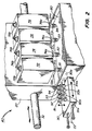
- the maintenance station 40 incorporates one or more high frequency actuable ultrasonic transducers 81, 82, 83, and 84 which transmit acoustic energy through a viscous liquid (fluid) medium. These ultrasonic transducers are mounted on a transducer platform 80.
- the maintenance station 40 also incorporates means for providing few drops of viscous fluid to provide a thin viscous layer 81a, 82a, 83a, 84a on the transducers 81, 82, 83 and 84 respectively.
- the characteristics of the viscous liquid to form a viscous meniscus are as follows:
- At least four wipers 91, 92, 93 and 94 are provided on the movable wiper platform 90 which is located in the maintenance station 40.
- An actuator 90a provides the bi-directional translation motion of the wiper platform 90.
- Wipers 91, 92, 93, 94 are equipped with actuators 91a, 92a, 93a, 94a for motion in the vertical direction.
- the wiper platform 90 moves slidably on two sliding rods 22 as the actuator 90a is prompted by the microprocessor 24.
- the wiper platform 90 can also be moved bi-directionally by a motor directly connected to the platform 90a or through a belt. Each wiper is dedicated to orifice structure of a specific cartridge.
- the microprocessor 24 see FIG.
- cartridge 72 may move across actuable ultrasonic transducer 81 for necessary cleaning action after which is moved to wiper 91 for wiping and can be capped immediately after wiping.
- the wipers 91, 92, 93 and 94 and actuable ultrasonic transducers 81, 82, 83 and 84 each are dedicated to corresponding cartridges 72, 74, 76, 78, respectively, for the purpose of eliminating any cross contamination of debris.
- the actuable ultrasonic transducers 81, 82, 83 and 84 and the actuators 90a, 91a, 92a, 93a and 94a are controlled electronically by the microprocessor 24 through a feedback circuit (not shown).
- the maintenance station 40 of FIG. 2 will be understood by those skilled in the art to be located in a region outside the printing zone at one end of the bi-directional movement of carriage 20. Cleaning is accomplished when the cartridges 72, 74, 76, 78 are moved by the carriage rod 32 to the maintenance station 40 where the wipers 91, 92, 93, and 94 are engaged in cleaning action.
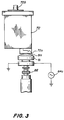
- a printhead ink cartridge 72 which includes an inlet for ink 72b and orifice plate 72a is shown in close proximity to but space from an actuable ultrasonic transducer head 81 to provide a thin high viscous layer of glycerin 81a between the actuable transducer head 81 and the orifice plate 72a.
- thin is meant that the thin high viscous layer has a thickness in the range of 0.1 to 1.0 mm thick.
- an electrical connector 86 which can be used for quickly connecting the actuable ultrasonic transducer 81 to a power supply 88.
- the wiper platform 90 includes the actuator 90a for horizontal bi-directional motion of a wiper base 48 and an actuator 91a for vertical motion of the wiper 91, is given.
- the wiper 91 shown in FIG. 4 has a razor like edge 43a for effective wiping action, but other shapes can also be applicable in this invention.
- the wiper 91 is mounted on a base 44 which is fastened to the actuator shaft 45.
- the wiper base 48 is moved bi-directionally by the actuator 90a and the motion is controlled by the microprocessor 24 (see FIG. 1).
- Other alternative means may be used to move the platform such as a motor directly connected to the wiper base 48 or through a belt or a lead screw (not shown).
Landscapes
- Ink Jet (AREA)
Applications Claiming Priority (2)
| Application Number | Priority Date | Filing Date | Title |
|---|---|---|---|
| US15972598A | 1998-09-24 | 1998-09-24 | |
| US159725 | 1998-09-24 |
Publications (1)
| Publication Number | Publication Date |
|---|---|
| EP0988977A1 true EP0988977A1 (fr) | 2000-03-29 |
Family
ID=22573749
Family Applications (1)
| Application Number | Title | Priority Date | Filing Date |
|---|---|---|---|
| EP99202982A Withdrawn EP0988977A1 (fr) | 1998-09-24 | 1999-09-13 | Nettoyage par ultrasons des cartouches de tête d'impression à jet d'encre |
Country Status (2)
| Country | Link |
|---|---|
| EP (1) | EP0988977A1 (fr) |
| JP (1) | JP2000094702A (fr) |
Cited By (3)
| Publication number | Priority date | Publication date | Assignee | Title |
|---|---|---|---|---|
| EP2233294A1 (fr) * | 2009-03-24 | 2010-09-29 | Xerox Corporation | Système de maintenance de tête d'impression pour imprimante à jet d'encre utilisant une impression à encre par changement de phase sur une toile continue |
| EP2783837A1 (fr) * | 2013-03-28 | 2014-10-01 | Ivoclar Vivadent AG | Procédé et dispositif destinés au montage en couches d'un corps de formage |
| CN110077109A (zh) * | 2019-06-06 | 2019-08-02 | 佛山市阿瑞斯陶瓷科技有限公司 | 一种在线式陶瓷喷墨机喷头快速清洗的设备及方法 |
Families Citing this family (1)
| Publication number | Priority date | Publication date | Assignee | Title |
|---|---|---|---|---|
| JP4652582B2 (ja) * | 2001-01-19 | 2011-03-16 | セイコーインスツル株式会社 | インクジェット記録装置およびインクジェットヘッドのクリーニング方法 |
Citations (4)
| Publication number | Priority date | Publication date | Assignee | Title |
|---|---|---|---|---|
| US4849769A (en) * | 1987-06-02 | 1989-07-18 | Burlington Industries, Inc. | System for ultrasonic cleaning of ink jet orifices |
| EP0437361A1 (fr) * | 1990-01-12 | 1991-07-17 | Hewlett-Packard Company | Onde mobile pour tête d'impression à jet d'encre |
| US5574485A (en) * | 1994-10-13 | 1996-11-12 | Xerox Corporation | Ultrasonic liquid wiper for ink jet printhead maintenance |
| US5741173A (en) * | 1995-12-15 | 1998-04-21 | Wacker Siltronic Gesellschaft Fur Halbleitermaterialien Ag | Method and apparatus for machining semiconductor material |
-
1999
- 1999-09-13 EP EP99202982A patent/EP0988977A1/fr not_active Withdrawn
- 1999-09-20 JP JP26504999A patent/JP2000094702A/ja active Pending
Patent Citations (4)
| Publication number | Priority date | Publication date | Assignee | Title |
|---|---|---|---|---|
| US4849769A (en) * | 1987-06-02 | 1989-07-18 | Burlington Industries, Inc. | System for ultrasonic cleaning of ink jet orifices |
| EP0437361A1 (fr) * | 1990-01-12 | 1991-07-17 | Hewlett-Packard Company | Onde mobile pour tête d'impression à jet d'encre |
| US5574485A (en) * | 1994-10-13 | 1996-11-12 | Xerox Corporation | Ultrasonic liquid wiper for ink jet printhead maintenance |
| US5741173A (en) * | 1995-12-15 | 1998-04-21 | Wacker Siltronic Gesellschaft Fur Halbleitermaterialien Ag | Method and apparatus for machining semiconductor material |
Cited By (6)
| Publication number | Priority date | Publication date | Assignee | Title |
|---|---|---|---|---|
| EP2233294A1 (fr) * | 2009-03-24 | 2010-09-29 | Xerox Corporation | Système de maintenance de tête d'impression pour imprimante à jet d'encre utilisant une impression à encre par changement de phase sur une toile continue |
| US8366237B2 (en) | 2009-03-24 | 2013-02-05 | Xerox Corporation | Print head maintenance system for an ink-jet printer using phase-change ink printing on a continuous web |
| EP2783837A1 (fr) * | 2013-03-28 | 2014-10-01 | Ivoclar Vivadent AG | Procédé et dispositif destinés au montage en couches d'un corps de formage |
| WO2014154641A1 (fr) * | 2013-03-28 | 2014-10-02 | Ivoclar Vivadent Ag | Procédé et dispositif de fabrication additive d'un article façonné |
| US20160059495A1 (en) * | 2013-03-28 | 2016-03-03 | Ivoclar Vivadent Ag | Method and device for constructing a shaped body layer-by-layer |
| CN110077109A (zh) * | 2019-06-06 | 2019-08-02 | 佛山市阿瑞斯陶瓷科技有限公司 | 一种在线式陶瓷喷墨机喷头快速清洗的设备及方法 |
Also Published As
| Publication number | Publication date |
|---|---|
| JP2000094702A (ja) | 2000-04-04 |
Similar Documents
| Publication | Publication Date | Title |
|---|---|---|
| EP1088665B1 (fr) | Système d'imprimante à jet d'encre auto-nettoyant à écoulement de fluide réversible et à rouleau tournant, et méthode d'assemblage du système d'imprimante | |
| US6267464B1 (en) | Self cleaning ink jet printhead cartridges | |
| EP1060894B1 (fr) | Nettoyage à plusieurs fluides pour têtes d'impression à jet d'encre | |
| EP1088664B1 (fr) | Système d'imprimante à jet d'encre auto-nettoyant à écoulement de fluide réversible et méthode d'assemblage du système d'imprimante | |
| EP0997290B1 (fr) | Nettoyage à ultrason à haute fréquence pour cartouches de tête d'impression à jet d'encre | |
| US6189999B1 (en) | Multi-faceted wiper scraper system for inkjet printheads | |
| EP1219433A1 (fr) | Imprimante et tête d'impression autonettoyante et son procédé de fabrication | |
| US6497472B2 (en) | Self-cleaning ink jet printer and print head with cleaning fluid flow system | |
| US6334662B2 (en) | Method and apparatus for cleaning an ink jet printhead | |
| JPH079712A (ja) | インクジェット記録装置 | |
| JP3327318B2 (ja) | インクジェット式記録装置 | |
| JP2000229416A (ja) | 振動隔壁及び超音波のある自己洗浄型インクジェットプリンターとそのプリンターの組立方法 | |
| JP2000229417A (ja) | 振動隔壁のある自己洗浄型インクジェットプリンターとそのプリンターの組立方法 | |
| EP0988977A1 (fr) | Nettoyage par ultrasons des cartouches de tête d'impression à jet d'encre | |
| JP3234087B2 (ja) | インクジェット記録装置 | |
| EP0976563A1 (fr) | Nettoyage par ultrasons sans contact pour cartouches de tête d'impression à jet d'encre | |
| JPH07101081A (ja) | インクジェット記録装置 | |
| EP0911171A1 (fr) | Nettoyage de buses d'imprimantes utilisant des vibrations | |
| JPH07223321A (ja) | インクジェット記録装置 | |
| JPH07205438A (ja) | インクジェット記録装置 | |
| JPH1044447A (ja) | インクジェットヘッドのメンテナンス装置 | |
| EP0936071B1 (fr) | Méthode et dispositif pour le nettoyage d'une tête d'impression à jet d'encre | |
| JP2005212141A (ja) | 液体噴射装置および液体噴射ヘッドのワイピング方法 | |
| JP3048022B2 (ja) | インクジェット記録装置 | |
| JP2816902B2 (ja) | インクジェット記録装置 |
Legal Events
| Date | Code | Title | Description |
|---|---|---|---|
| PUAI | Public reference made under article 153(3) epc to a published international application that has entered the european phase |
Free format text: ORIGINAL CODE: 0009012 |
|
| AK | Designated contracting states |
Kind code of ref document: A1 Designated state(s): AT BE CH CY DE DK ES FI FR GB GR IE IT LI LU MC NL PT SE |
|
| AX | Request for extension of the european patent |
Free format text: AL;LT;LV;MK;RO;SI |
|
| AKX | Designation fees paid | ||
| STAA | Information on the status of an ep patent application or granted ep patent |
Free format text: STATUS: THE APPLICATION IS DEEMED TO BE WITHDRAWN |
|
| 18D | Application deemed to be withdrawn |
Effective date: 20000930 |
|
| REG | Reference to a national code |
Ref country code: DE Ref legal event code: 8566 |