EP0988903B1 - Verfahren zum Walzen eines Metallproduktes - Google Patents
Verfahren zum Walzen eines Metallproduktes Download PDFInfo
- Publication number
- EP0988903B1 EP0988903B1 EP99402297A EP99402297A EP0988903B1 EP 0988903 B1 EP0988903 B1 EP 0988903B1 EP 99402297 A EP99402297 A EP 99402297A EP 99402297 A EP99402297 A EP 99402297A EP 0988903 B1 EP0988903 B1 EP 0988903B1
- Authority
- EP
- European Patent Office
- Prior art keywords
- rolling
- metal
- deformation
- pass
- product
- Prior art date
- Legal status (The legal status is an assumption and is not a legal conclusion. Google has not performed a legal analysis and makes no representation as to the accuracy of the status listed.)
- Revoked
Links
Images

Classifications
-
- B—PERFORMING OPERATIONS; TRANSPORTING
- B21—MECHANICAL METAL-WORKING WITHOUT ESSENTIALLY REMOVING MATERIAL; PUNCHING METAL
- B21B—ROLLING OF METAL
- B21B37/00—Control devices or methods specially adapted for metal-rolling mills or the work produced thereby
- B21B37/58—Roll-force control; Roll-gap control
Definitions
- the subject of the invention is a method of rolling a metallic product and applies more particularly to hot rolling of flat products such as slabs or strips from a roughing or casting rolling mill continuous, (see for example WO 93/11886).
- Hot rolling is usually done by successive rolling passes in an installation comprising one or more rolling stands.
- Each cage can be used as a reversible rolling mill performing a number of reduction passes, alternately back and forth, until you get the desired thickness. But we can also perform a single rolling pass in each cage.
- the installation then operates in a tandem rolling mill, the rolled product being taken simultaneously in all cages and its thickness successively reduced in each cage.
- the invention applies especially to rolling with hot steels and their alloys but is also usable, under certain conditions, for the rolling of non-ferrous metals such as aluminum and its alloys.
- a rolling mill includes a cage rigid support having two columns spaced between which are placed at least two working cylinders superimposed which define a product passage air gap to laminate.
- the working cylinders are each supported on a cylinder larger diameter support.
- intermediate cylinders are interposed between working cylinders and support cylinders.
- At least the support cylinders are provided, at their ends, of trunnions turning in chocks sliding mounted in fitted windows respectively on the two columns of the cage, parallel to a clamping plane, generally vertical, passing substantially through the axes of the working cylinders.
- the rolling mill is associated with means for controlling the scrolling of the product between the cylinders, at a certain forward speed.
- advancement control means are constituted, usually two roller tables, respectively, one roller table placed upstream of the cage, in the direction of scroll, to order product engagement and a other roller table placed downstream to receive the product after rolling.
- the product In hot rolling, the product is heated, before rolling, up to a temperature of around 1200 ° C in the case of steel, so as to facilitate the deformation of the metal and its flow between the cylinders.
- the product in a process of rolling, the product has a thickness greater than the spacing of the cylinders and, when it comes into contact with them, it is driven by friction then pinched between the two cylinders, with metal flow and thickness reduction, up to thickness substantially equal to the spacing between the generators opposite the two working cylinders.
- Laminating is therefore carried out from a part raw such as a slab or strip having a thickness variable which can range from a few millimeters to several hundreds of millimeters and a pass is made on each pass thickness reduction which can vary, for example, by 50 mm to a few tens of millimeters.
- clamping means therefore serve, on the one hand to prior adjustment of the spacing between the cylinders and, on the other hand, to the maintenance of it during the pass of rolling.
- They generally consist of screws or hydraulic cylinders mounted on the cage and supported respectively on the two chocks of a cylinder of support, the other being blocked in height.
- support cylinders with an envelope rotatably mounted around a fixed shaft and supported by this via a series of cylinders. These then constitute clamping means exerting the force of rolling which is thus distributed over the entire length of the air gap.
- the rolling force to be applied to maintain of a given spacing between the cylinders depends on the deformation conditions of the product in the grip of passage between the cylinders.
- the maximum thickness reduction possible is a function of the rolling force that we can apply, taking into account the capacities of the rolling mill.
- the reduction in thickness that can be achieved with each pass is therefore limited and this is why the rolling of a raw product is normally carried out in several successive passes, each determining an elementary thickness reduction compatible with the capacity. of the rolling mill.
- the total thickness reduction from a gross thickness e o to a final thickness e n can be obtained in n passes according to a process of progressive thickness reduction, called rolling scheme, which depends on the capacity of the rolling mill and the adjustment means available, the mechanical and physical characteristics of the stand and of the product, as well as the tolerances to be observed in terms of thickness and flatness.
- the invention remedies this drawback and has for object, thanks to advances in modeling, a new process for determining more precisely the rolling force to be applied to comply with a rolling.
- the invention makes it possible to act automatically and in real time on the settings of the rolling mill to change these on each pass depending measurements made in the previous pass, so that continuously adapt the rolling scheme by optimizing the settings for each pass.
- the computer associated with the mathematical model determines, before each pass x, a predictable value of the flow stress of the metal corresponding to the deformation to be carried out in the pass x considered, taking into account the evolution, during rolling, the microcrystalline structure of the metal constituting the product to be laminated, and the rolling force F x to be applied to obtain the desired thickness reduction is calculated before each pass x as a function of the value thus provided for the stress flow and its evolution during rolling.
- the rolling force F x to be applied for a rolling pass is calculated by taking account of the foreseeable variation, along the right-of-way, of the flow stress of the metal during said pass x.
- the rolling area is divided into a series of p adjacent elementary slices M i , M 2 , ... M i , .... M p , each corresponding to an elementary length of advance of the product between the cylinders, with an elementary deformation ⁇ i of the product in each slice M i between an inlet section of thickness e i-1 and an outlet section of thickness e i , that, from the indications given by the model mathematically, the computer determines, for each slice M i , a predictable value ⁇ i of the metal flow stress, corresponding to said elementary deformation ⁇ i and deduces therefrom the elementary rolling force dF i to be applied in the slice considered Mi to carry out said elementary deformation ⁇ i and that, by integration of the elementary forces dF i in the successive slices M 1 , M 2 , ...
- the computer determines the overall rolling force to be applied for perform the re duction of desired thickness, and controls, as a function of the overall force thus calculated, the adjustment of the clamping means for maintaining the spacing of the cylinders making it possible to obtain the desired reduction in thickness e x-1 -e x , taking into account the flow conditions of the metal along the right-of-way and the yielding effect resulting from said overall force.
- the invention also makes it possible to determine the rolling force F x to be applied during a pass x by taking into account the foreseeable value of the metal flow stress resulting from the evolution of the microcrystalline state of the metal during the previous passes.
- the rolling is carried out according to a rolling scheme allowing an overall thickness reduction e o -e n to be carried out in n successive passes, each rolling pass x effecting a thickness reduction e x-1 -e x .
- the calculator determines, by iteration, the rolling scheme to be observed by calculating in advance, for each pass x, the maximum thickness reduction leading to a force of predictable rolling Fx compatible with the capacity of the rolling mill, depending on a set of parameters rolling including product thickness and temperature and its forward speed before entering said pass x, so as to take account of the foreseeable development of the microstructure of the metal from one pass to the next.
- the computer can be associated with permanent measurement means, during the pass, effective values of a set of parameters of rolling including the rolling force applied to each instant, the speed of advancement of the product and the temperature of the latter respectively at the inlet and at the exit from the rolling mill.
- the calculator can compare these actual measured values with the values said parameters taken into account initially for said pass x in determining the rolling pattern, so as to resume the calculation of it and introduce, in where necessary, correction factors to parameters taken into account, in order to adapt the rolling scheme in the following passes.
- equations of modeling having been established initially for a standard metal and implanted in the mathematical model, these equations can be calibrated on the metal to be laminated, first performing at least one rolling pass, at least at least one product consisting of the metal to be laminated, in at least a rolling mill stand set in a conventional manner and measuring, during each pass, on the one hand the force of rolling actually exercised and, on the other hand, the parameters used by the computer to determine, at using the initial modeling equations, the strength of lamination to exercise theoretically.
- a method of numerical regression we can determine the modifications to bring to the parameters of said initial equations of so as to obtain modeling equations specific to metal to be laminated.
- the coefficients k and k 'of the first modeling equation can be determined by the calculator following a numerical regression method, from temperature and representative parameters the crystalline state of the metal at the entrance to the cage.
- the computer determines before each pass, as a function of the rolling parameters measured at the entry of the stand, the predictable flow stress ⁇ i in each of said slices M i by digital integration inverse of the second modeling equation as a function of the elementary deformation ⁇ i to be produced in the section considered M i and deduces therefrom the elementary rolling force dF i to be applied in said section M i , the overall rolling force being calculated by integration said elementary forces along the right-of-way.
- the process according to the invention can be integrated at several levels into the rolling process.
- the calculator can check whether the overall rolling force calculated in as a function of the thickness reduction provided for in the diagram lamination is compatible with the capacities of the installation and if said planned thickness reduction uses, so said capacities and modify, if necessary, the rolling scheme for the following passes.
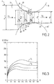
- Figure 1 shows schematically a cage of rolling associated with tightening control means according to the invention.
- Figure 2 schematically illustrates the process of rolling of the product between two working rolls.
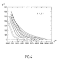
- Figure 3 is a diagram showing the evolution of the flow stress of the rolled metal as a function of deformation in the grip.
- Figure 4 is a diagram showing the evolution of the rate of work hardening of the metal in the grip in function of the flow stress.
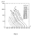
- Figure 5 is a work hardening diagram illustrating a new representation of the evolution of flow conditions in the right of way.
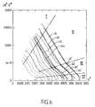
- Figure 6 illustrates the use of the diagram of hardening for the establishment of the equations of modelization.
- FIG. 1 shows schematically a cage rolling 1 consisting, as usual, of two spread columns 11 connected by crosspieces not represented and between which are placed several superimposed cylinders.
- the cage is quarto type and therefore includes two working cylinders 12, 12 'defining an air gap 10 of the passage of the product 2 to laminate and resting on the side opposite the product, respectively on two additional support cylinders 13, 13 ' large diameter.
- Each cylinder is rotatably mounted at its ends, on two pins carried by bearings mounted in chocks, respectively working 14, 14 ' and support 15, 15 '. These are strung in windows on the two columns 11 of the cage and provided with guide faces along their sides from which slide the chocks of the cylinders, parallel to a clamping plane P in which are placed substantially the axes of the cylinders.
- the cage 1 is also associated with means product progress, for example, two roller tables 16, 16 'placed on either side of the cage in the case a reversible rolling mill.
- the rollers of the table rollers 16 placed upstream are rotated by in order to control the progress of product 2 which commits between the working cylinders 12 or 12 'and is driven by friction in the air gap 10. After reduction of its thickness, product 2 is received by the roller table downstream 16 '.
- the difference between the width of the air gap and the initial thickness of the product must be limited to avoid a refusal of engagement given the diameter of the cylinders 12, 12 'and of the thrust force exerted by the roller table 16.
- the cage is therefore provided with clamping means, for example jacks hydraulic or mechanical 17, mounted on each column 11 and bearing on the chocks 15 of the support cylinder upper 13, lower support chocks 15 ' can be simply supported by wedges 18.
- clamping means for example jacks hydraulic or mechanical 17, mounted on each column 11 and bearing on the chocks 15 of the support cylinder upper 13, lower support chocks 15 ' can be simply supported by wedges 18.
- the clamping means are jacks hydraulics 17 conventionally supplied by a circuit globally identified by reference 3, associated with a servovalve 31 controlled by a regulator 32.
- the regulator 32 is associated with position sensors 33 and position sensors pressure 34.
- the clamping means 17 can be controlled in position and pressure, so that determine, on the one hand the spacing e of the generators supporting working cylinders 12, 12 'determining the thickness of the air gap 10 and, on the other hand, the maintenance the spacing chosen during rolling, by application, between the cylinders, a clamping force called the force of rolling, which can be measured by the sensor 34.
- the spacing of the cylinders can also be regulated by separate cylinders, the cylinders clamping 17 then essentially serving to apply the rolling force to maintain the gap.
- the cage 1 is also provided with other sensors for measuring the various rolling parameters, by example of pyrometers 35, 35 'for temperature measurement of product 2, respectively before entering the cage and after leaving it, as well as means 36 of measurement of the speed of rotation of one of the cylinders work, to determine the speed of advancement of the product in the right-of-way between the cylinders.
- the signals from all the sensors and corresponding to the measurements carried out are displayed in inputs of a central measurement. 4 which includes a unit of calculation capable of developing a control signal from the regulator 32 for controlling the clamping means of so as to adjust and maintain the desired spacing between the working cylinders 12, 12 '.
- the calculation unit 4 comprises a calculator 40 associated with a programmed mathematical model of in order to calculate the rolling force very precisely to apply, from modeling equations representative of the behavior of the metal and, in particular, of its flow conditions in the right of way between the cylinders.
- FIG. 2 schematically illustrates the process of reducing the thickness of the metal product 2 between the two cylinders 12, 12 '.
- the product 2 comprises an upstream part 21, of thickness e x-1 , a central part 22 corresponding to the passage area between the cylinders which is limited by two contact arcs 20, 20 ', and a downstream part 23 having a thickness e x which, in practice, is slightly greater than the spacing e ' x of the working rolls 12, 12'.
- the roller table 16 determines the progress of the product at a speed V1 of engagement in the rolling mill.
- the end front of product 2 then comes into contact with the two cylinders 12, 12 '.
- the friction between the cylinder wall and the product determines its engagement in the grip between the cylinders, with thickness reduction and metal flow. This results in a slight widening of the product but, essentially, an elongation of it, the amount of metal being retained. Therefore, the downstream part 23 of the product advances at a higher speed V2 to V1.
- the two cylinders 12, 12 ' are rotated at a certain angular speed and, conventionally, we distinguishes a neutral point 24 of the product for which the tangential forward speed V3 is equal to the speed peripheral cylinders 12, 12 '.
- the tangential speed of advancement of the product therefore increases gradually from V1 to V2. It is lower than V3 in upstream of the neutral section 24 and higher than V3 downstream.
- the friction factor Q f which is a function of the ratio of the length L of the contact arc 20 to the average thickness h of the product, can be estimated with fairly good accuracy.
- the outlet thickness e x is slightly greater than the actual thickness e ' x of the air gap between the cylinders, the difference being able to be determined in a known manner.
- the K factor depends on the temperature, the composition of the product and its structure but we observed that it was also necessary to involve phenomena complexes such as the evolution of the microstructure metallic during deformation.
- the object of the invention is a new process in which the overall rolling force to be applied can be more accurately determined by giving them ways to take into account the evolution of the microstructure crystal of the metal during rolling to estimate the value of the flow stress ⁇ of the metal at a time determined of the rolling.
- the depositor has conducted studies metallurgical very advanced with a large number laboratory experiments that have led to a new representation of the parameters representative of the intimate evolution of the microstructure of steel, allowing a modeling of this evolution according to overall rolling objectives (thickness reduction, flatness, temperature), this representation leading to modeling equations programmed in the model mathematical and likely to be integrated by the computer 40 associated with the central 4 for controlling rolling mill actuators.
- the method according to the invention makes it possible to take account the evolution of the metal flow conditions, a part during successive passes and on the other hand, the along the right-of-way, in the same pass.
- each elementary section M i corresponds to an elementary length of advance l i of the product between the cylinders, with an elementary deformation ⁇ i which is defined, in known manner, from the reduction of thickness e i-1 -e i to be carried out in the section considered, e i-1 being the thickness of the entry section of the section and e i the exit thickness.
- dislocation density ⁇ This quantity, which can be measured on a sample metallic using an electron microscope in transmission, represents the cumulative length, per unit of volume of metal, linear crystal defects called dislocations.
- the invention makes it possible, on the contrary, to take account of the variation of the flow stress linked to the evolution of the microstructure during rolling and therefore provides the means to estimate much more specifies that previously the rolling force to be applied for obtain and maintain the desired thickness reduction at each pass.
- Figure 4 gives an example of this first diagram work hardening, each curve representing the variation of the normalized rate of work hardening en * according to the stress of normalized flow ⁇ *, for a temperature T and a constant strain rate ⁇ ⁇ .
- each curve has at least two parts practically rectilinear, these rectilinear parts being, in each area, substantially parallel to each other.
- each type of steel has its own specific diagram and in each diagram each curve and therefore each line corresponds to a temperature and at a determined rate of deformation but interpolations are possible.
- Each work hardening diagram, established from test results, corresponds to a steel of composition determined.
- FIGS. 3 to 6 have been established experimentally for a steel having the following composition, in percentages by weight: C: 0.08; Mn: 1.1; If: 0.25; Fe: the rest.
- the parameters (11) on which the law of evolution depends of the model can be identified from tests, by example of homogeneous hot compression performed in laboratory, each at deformation speed and constant temperatures, so as to determine the curves representative stress-strain studies of behavior of steel under these conditions.
- the parameters k II , k III which are the slopes of the lines being used for the modelization of the law of hardening, respectively in domains II and III depend only on the composition of the steel and its grain size, that is to say the crystalline state which the metal has reached after the various successive rolling passes.
- the parameters x s2 , x s3 depend, moreover, on the strain rate ⁇ ⁇ and on the temperature T.
- the metal deformation rate can be determined at each point of the right-of-way, depending on the reduction in thickness to be carried out and the speed of rolling.
- the mathematical model can estimate the product temperature and the rate of deformation in the section M i considered to deduce the right of the diagram of FIG. 6 and , the modeling equations (9, 10) applicable in this section, by making the interpolations necessary to take account of the temperature and the speed of deformation when these do not correspond to those of the tests.
- the computer can determine, for each slice M i , the predictable value ⁇ i of the flow stress corresponding to the deformation elementary ⁇ i to be produced and then draw from it the estimated value of elementary rolling force dF i to be applied in said slice M i .
- the computer can then, by integration, determine the overall rolling force F x to be applied to the whole of the right-of-way by the clamping means 27 during the pass x.
- the calculator takes into account mechanical and physical characteristics of the product, in particular of its elasticity, to determine the slight increase in the thickness of the product that is produced, known manner, at the exit of the rolling mill.
- the computer can therefore determine very precisely the air gap e ' x which will have to be adjusted and maintained between the working rolls 12, 12' to obtain the desired thickness reduction e x-1 -e x and controlling, during the pass considered, the adjustment of the clamping means, so as to apply between the rolls the rolling force actually necessary to maintain this air gap.
- a first method performs tests on a selection of steels beforehand representative of a chemical composition domain for which one wishes to calibrate the model with, for each of them, different initial grain size values, which determine the starting state of the metal microstructure.
- tests are carried out for different values temperature and rate of deformation so that cover an area of demand corresponding to efforts developed during the different passes of rolling and for which the model is established.
- the way the model takes into account the evolution of the metal structure also allows implement a simpler calibration method, by particular for laminating products made of steel leaving the field of chemical composition for which the model had been programmed.
- tests on test pieces are simply replaced by the first passes of rolling carried out on the product to be rolled with a setting manual.
- model math associated with the computer could be programmed, as indicated above, from tests carried out on a typical metal.
- the programmed equations are thus calibrated on the new metal depending on its behavior in rolling course, from the indications given by the passes manually adjusted.
- differential equations (10) and (11) established as indicated above allow, in because of their linear nature, to link in the two sense the deformation ⁇ to the flow stress ⁇ because they can be integrated in a sense, analytically, to express the deformation as a function of the stress, and the other way, digitally, to connect the strain stress.
- the computer can therefore recalculate the force to be applied between the cylinders under actual rolling conditions observed to compare it to the force measured during the same rolling pass.
- This comparison allows a adaptation of the game (12) of the parameters of the law of evolution defined by modeling equations and recalculate with these coefficients readjusted, the adjustment of the rolling mill for the next pass, and so on, for each pass of the rolling scheme initially planned by the strategy.
- the model can take into account the measurements performed during rolling to introduce factors of correction to the values of the parameters of the law evolution predetermined by laboratory data.
- the method according to the invention allows the calculation of the rolling diagram in order to modify it for the passes of reduction remaining to be executed, this readjustment operation and of verification being carried out during each pass of rolling until the final thickness is obtained.
- the method according to the invention is therefore applicable successively at the start of rolling then, at each step, by determining both the precision of the tolerances of the manufactured product as well as the optimization of the use of the industrial production tool.
- the process can be integrated into the strategy for calculating the rolling scheme using a method iterative optimization taking into account the data general of the installation and those of the product.
- the computer 40 before rolling, receives general data relating to product entering the rolling mill, the chemical composition of steel, gross product thickness, temperature at the entrance to the rolling mill, the final thickness targeted, etc. that the predictable flow stress and the force of lamination to be applied to achieve thickness reduction data can be accurately calculated it's possible, at each pass, to check if the reduction of thickness provided for by the rolling scheme leads to a excessive rolling force, requiring a decrease in this reduction in thickness or, on the contrary, if we can achieve greater thickness reduction leading to an acceptable rolling force.
- the calculator associated with the mathematical model can adapt the rolling scheme so as to use the capabilities of installation in optimal conditions, the model can effectively take into account, on each pass, the state of the product leaving the previous pass.
- the invention is not limited to details of the embodiments which have just been described, the process being adaptable to the circumstances in remaining within the protection framework defined by the claims.
- the figure shows a quarto rolling mill, the process being applicable in the same way to a duo, a sexto or any other type of hot rolling mill.
- the invention has been described for a rolling stand, but is applicable in the same way to all cages, reversible or not, a hot rolling installation, these cages can be insulated to constitute the roughing of a train to strips, hot or work in tandem, for example to constitute the finisher of the band train, or form a unit operating in continuous tandem.
- the idea of the invention being to estimate the metal flow stress using the knowledge acquired on the behavior of metals, such that the Taylor and Sims relationships or the Choquet model, we could obviously take advantage of the evolution of these knowledge to improve or modify the process by taking into account, in another way, the evolution of metal structure during deformation.
Landscapes
- Engineering & Computer Science (AREA)
- Mechanical Engineering (AREA)
- Control Of Metal Rolling (AREA)
- Laminated Bodies (AREA)
- Forging (AREA)
- Metal Rolling (AREA)
Claims (19)
- Verfahren zum Walzen eines Metallproduktes durch sukzessive Walzstiche in einer Anlage bestehend aus:dadurch gekennzeichnet, dass die einem mathematischen Modell (40) zugeordnete Recheneinheit (4) vor jedem Walzstich (x) unter Berücksichtigung der beim Walzen der das zu walzende Erzeugnis (2) bildenden Metall-Mikrostruktur erfolgenden Entwicklung einen vorhersehbaren Wert der Metall-Fließspannung bestimmt, welcher der in dem betreffenden Walzstich (x) zu erzielenden Verformung entspricht, und dass die zur Erzielung der gewünschten Dickenminderung (ex-1-ex) aufzubringende Walzkraft (Fx) vor jedem Walzstich (x) entsprechend dem so vorhergesehenen Wert der Fließspannung und der Entwicklung derselben beim Walzen berechnet wird.einem Walzgerüst (1) mit zwei im Abstand angeordneten Ständern (11),mindestens zwei zwischen den Walzgerüstständern übereinander liegenden Arbeitswalzen (12, 12'),Steuermitteln (16) zum Vorschub des Produktes (2) bei dessen Walzung in einem durch zwei Kontaktbögen (20, 20') des Produktes (2) mit den beiden Walzen (12, 12') begrenzten Walzspalt (22) zwischen einem Einlaufquerschnitt und einem Auslaufquerschnitt des Walzspaltes (22),Anstellmitteln (17), die sich zur Einstellung eines einer auszuführenden Dickenabnahme entsprechenden Abstandes (10) zwischen den Arbeitswalzen (12, 12') und zum Einhalten dieses Abstandes während des Walzstiches jeweils auf den Walzen und auf dem Walzgerüst (1) durch Aufbringen einer Walzkraft zwischen den Arbeitswalzen (12, 12'), die von den mechanischen und physischen Merkmalen des Walzgerüstes (1) und des Produktes (2) und den Fließbedingungen des Metalls im Walzspalt abhängt und einen Effekt des Nachgebens der verschiedenen Walzgerüstteile bewirkt, der dazu tendiert, diesen Abstand zu vergrößern, abstützen,Mitteln (31, 32), die zur Einstellung der Anstellmittel über eine Recheneinheit (4) mit einem einem mathematischen Modell zugeordneten Rechner (40) gesteuert werden,
- Walzverfahren nach Anspruch 1, dadurch gekennzeichnet, dass die für einen Walzstich (x) aufzubringende Walzkraft (Fx) unter Berücksichtigung der bei diesem Walzstich (x) vorhersehbaren Schwankung der Metall-Fließspannung entlang des Walzspaltes (22), berechnet wird.
- Walzverfahren nach Anspruch 2, dadurch gekennzeichnet, daß der Walzspalt zur Berücksichtigung der Fließspannungsschwankung in p benachbarte Elementarabschnitte (M1, M2, ... Mi, ... Mp) unterteilt wird, die jeweils einer Produktvorschubelementarlänge zwischen den Walzen mit einer Elementarverformung (∈i) des Produktes in jedem Abschnitt (Mi) zwischen einem Einlaufquerschnitt der Stärke (ei-1) und einem Auslaufquerschnitt der Stärke (ei) entsprechen, dass der Rechner (4, 40) von den durch das mathematische Modell gelieferten Angaben ausgehend für jeden Abschnitt (Mi) einen vorhersehbaren, dieser Elementarverformung (εi) entsprechenden Wert (σi) der Metall-Fließspannung bestimmt und daraus die zur Erzielung dieser Elementarverformung (∈i) in dem betreffenden Abschnitt aufzubringende Elementarwalzkraft (dFi) ableitet und dass der Rechner die zur Erzielung der gewünschten Dickenminderung insgesamt aufzubringende Walzkraft mittels Integration der Elementarkräfte (dFi) in den aufeinander folgenden Abschnitten (M1, M2, ... Mi, ... Mp) bestimmt und die Regelung der Anstellmittel (17) zum Einhalten des Abstandes (e'x) der Walzen (12, 12'), durch den die gewünschte Dickenminderung (ex-1-ex) erzielt werden kann, entsprechend der so berechneten Gesamtkraft unter Berücksichtigung der Metall-Fließbedingungen entlang des Walzspaltes und des aus dieser Gesamtkraft resultierenden Durchbiegungseffekts steuert.
- Verfahren nach einem der Ansprüche 1, 2 und 3, dadurch gekennzeichnet, daß die bei einem Walzstich (x) aufzubringende Walzkraft (Fx) unter Berücksichtigung des vorherzusehenden Wertes der Metall-Fließspannung, der sich aus der Entwicklung der mikrokristallinen Metallbeschaffenheit während der vorherigen Walzstiche ergibt, bestimmt wird.
- Walzverfahren nach einem der Ansprüche 1 bis 4, bei dem der Walzvorgang nach einem Walzplan erfolgt, der eine gesamte Dickenminderung (eo-en) in n aufeinander folgenden Walzstichen ermöglicht, wobei bei jedem Walzstich (x) eine Dickenminderung (ex-1-ex) erzielt wird, dadurch gekennzeichnet, dass die Recheneinheit (4, 40) den einzuhaltenden Walzplan durch Iteration bestimmt, indem sie für jeden Walzstich (x) die zu einer mit der Belastbarkeit des Walzwerkes (1) vereinbaren vorhersehbaren Walzkraft Fx führende maximale Dickenminderung in Abhängigkeit von einem Satz Walzparameter bestehend aus der Dicke und der Temperatur des Produktes (2) und dessen Vorschubgeschwindigkeit vor dem Einlauf in diesen Walzstich (x) im voraus errechnet, um somit beim betreffenden Walzstich (x) der vorhersehbaren Entwicklung des Metall-Mikrogefüges von einem Walzstich zum folgenden und entlang des Walzspaltes Rechnung zu tragen.
- Walzverfahren nach Anspruch 5, dadurch gekennzeichnet, daß der Recheneinheit (4) Mittel (34, 35, 36) zum ständigen Messen der effektiven Werte eines aus der im jeweiligen Meßzeitpunkt beaufschlagten Walzkraft, der Vorschubgeschwindigkeit des Produktes (2) und der jeweiligen Temperatur desselben am Einlauf und am Auslauf des Walzwerkes (1) bestehenden Satzes Walzparameter während des Walzstichs zugeordnet sind, und daß die Recheneinheit (4) diese effektiven Meßwerte bei jedem Walzstich (x) mit den Werten der bei der Festlegung des Walzplans ursprünglich für diesen Walzstich (x) berücksichtigten Parameter vergleicht, um die Berechnung desselben wieder aufzunehmen und, falls erforderlich, in die berücksichtigten Parameter Korrekturgrössen zwecks Anpassung des Walzplans für die folgenden Walzstiche einzufügen.
- Walzverfahren nach einem der Ansprüche 3 bis 6, dadurch gekennzeichnet, daß der vorhersehbare Wert (σi) der Fließspannung in jedem Abschnitt (Mi) des Walzspaltes (22) von der Recheneinheit (4, 40) entsprechend der Lage des betreffenden Abschnittes des Walzspaltes (22) unter Berücksichtigung der vor dem Einlauf des Produktes (2) in das Walzgerüst (1) gemessenen Metalltemperatur, der Verformungsgeschwindigkeit in diesem Abschnitt (Mi) und der Entwicklung des kristallinen Zustands des Produkts beim Walzen in den vorherigen Walzstichen und entlang des Walzspaltes in dem betreffenden Walzstich (x) bestimmt wird.
- Walzverfahren nach einem der vorangehenden Ansprüche, dadurch gekennzeichnet, daß zur Berücksichtigung der Entwicklung der mikrokristallinen Metallstruktur beim Walzen mindestens eine für eine Familie von Metallen gleichartigen mikrokristallinen Verhaltens gültige Modellierungsgleichung auf der Grundlage von an Proben mindestens eines für diese Familie typischen Metalls durchgeführten Warmverformungsversuchen erstellt wird, wobei diese Gleichungen von einem Satz mit der Zusammensetzung des typischen Metalls verbundener Parameter abhängig sind, daß die so erstellten ursprünglichen Gleichungen in das mathematische Modell eingesetzt werden und daß zum Walzen eines aus einem Metall derselben Familie wie das typische Metall bestehenden Produkts das Modell unter Abänderung der Parameter dieser theoretischen Gleichungen gemäß den Ergebnissen von mit einem Metall einer dem zu walzenden Metall mindestens benachbarten Zusammensetzung durchgeführten Verformungsversuche, auf das zu walzende Metall angewendet wird.
- Walzverfahren nach Anspruch 8, dadurch gekennzeichnet, daß zur Festlegung der Modellierungsgleichungen eine mit der Metallverformungsgeschwindigkeit verbundene und entsprechend der Fließspannung in mindestens einem Verformungsbereich (II) im wesentlichen linear schwankende Zwischengrösse bestimmt wird und auf der Grundlage von für eine Reihe konstant gehaltenen Temperaturen und Verformungsgeschwindigkeiten durchgeführten Verformungsversuchen ein Kaltverfestigungsdiagramm erstellt wird, auf dem die Schwankungen dieser Zwischengrösse in diesem Verformungsbereich (II) durch mindestens eine Schar Geraden (61, 62...), denen mindestens eine die Verformung mit der Fließspannung verbindende und durch den Rechner (40) integrierbare lineare Differentialgleichung entspricht, näherungsweise dargestellt werden können.
- Walzverfahren nach Anspruch 9, dadurch gekennzeichnet, daß auf der Grundlage des Kaltverfestigungsdiagramms mindestens zwei die Verformung mit der Fließspannung verbindende Differentialgleichungen erstellt werden, von denen eine erste lineare Gleichung durch analytische Integration einen Verformungsausdruck entsprechend der Fließspannung liefert und eine zweite numerisch integrierbare Gleichung zur Bestimmung der vorhersehbaren Fließspannung einer zu erzielenden Verformung dient.
- Walzverfahren nach einem der Ansprüche 8 bis 10, dadurch gekennzeichnet, daß die Modellierungsgleichungen auf der Grundlage von Ergebnissen von bei verschiedenen für jeden Test konstant gehaltenen Temperaturen und Verformungsgeschwindigkeiten durchgeführten Warmverformungsversuchen an einer Reihe von Proben aus mindestens einem Metall mit einer derjenigen des zu walzenden Produkts mindestens benachbarten Zusammensetzung erstellt werden.
- Walzverfahren nach Anspruch 11, dadurch gekennzeichnet, daß die Modellierungsgleichungen auf der Grundlage von an Proben durchgeführten homogenen Warmpressversuchen erstellt werden.
- Walzverfahren nach einem der Ansprüche 11 und 12, dadurch gekennzeichnet, daß die Erstellung der Modellierungsgleichungen auf der Grundlage mehrerer Serien von Warmverformungsversuchen erfolgt, die mit mehreren Reihen von Metallproben mit einer in jeder Reihe bestimmten Zusammensetzung durchgeführt werden, wobei die Zusammensetzungen der verschiedenen Reihen derart gewählt werden, daß sie eine Auswahl von für eine Gruppe von Zusammensetzungen typischen Metallen auf die sich das Modell stützt, mit ursprünglich unterschiedlichen Komgrössenwerten abdecken, und wobei die Versuche für jede Reihe bei unterschiedlichen typischen Temperaturen und Verformungsgeschwindigkeiten eines Beanspruchungsbereichs, auf den sich das Modell stützt, unter Berücksichtigung der vorhersehbaren Walzbedingungen durchgeführt werden.
- Walzverfahren nach einem der Ansprüche 8 bis 10, dadurch gekennzeichnet, daß die Modellierungsgleichungen ursprünglich für ein typisches Metall erstellt und in das mathematische Modell eingebaut werden, und daß zum Anwenden dieser Gleichungen auf das zu walzende Metall zuerst mindestens ein Walzstich eines aus dem zu walzenden Metall bestehenden Erzeugnisses in mindestens einem herkömmlich eingestellten Walzgerüst (1) durchgeführt wird, wobei zur Bestimmung der theoretisch aufzubringenden Walzkraft mit Hilfe der ursprünglichen Modellierungsgleichungen in jedem Walzstich einerseits die wirklich beaufschlagte Walzkraft und andererseits die von der Recheneinheit (4, 40) benutzten Walzparameter gemessen werden, und zum Erhalten der für das zu walzende Metall spezifischen Modellierungsgleichungen die an den Parametern dieser ursprünglichen Gleichungen vorzunehmenden Änderungen mittels einer numerischen Regreßmethode bestimmt werden.
- Walzverfahren nach einem der Ansprüche 8 bis 14, dadurch gekennzeichnet, daß auf der Grundlage der Ergebnisse der jeweils bei konstanter Temperatur und Verformungsgeschwindigkeit durchgeführten Versuche mindestens ein Verformungsbereich (II, III) bestimmt wird, für den eine erste lineare Modellierungsgleichung erstellt werden kann, die den Ausdruck der Schwankungen einer Zwischenfunktion der mit der Verformungsgeschwindigkeit verbundenen Fließspannung liefert und von der ausgehend mittels analytischer Integration eine zweite Modellierungsgleichung bestimmt wird, welche in diesem Bereich (II, III) einen Ausdruck der Verformung entsprechend der Fließspannung liefert, und der Rechner mittels umgekehrter numerischer Integration dieser zweiten Gleichung, entsprechend der zu erzielenden Verformung und für jeden Walzstich unter Berücksichtigung der Walzparameter am Walzgerüsteinlauf, den vorhersehbaren Wert der Metallfließspannung bestimmt und daraus die zu beaufschlagende Walzkraft zur Erzielung dieser Verformung ableitet.
- Walzverfahren nach Anspruch 15, dadurch gekennzeichnet, dass auf der Grundlage der Ergebnisse der jeweils bei konstanter Temperatur und Verformungsgeschwindigkeit durchgeführten Versucheein erstes Kaltverfestigungsdiagramm mit einer Reihe für jede Temperatur T typischer Schwankungskurven der Kaltverfestigungsrate = dσ / d∈ in Abhängigkeit von der Fließspannung σ erstellt wird,die numerischen Daten jeder Kurve zur Erstellung eines zweiten, normalisierten Kaltverfestigungsdiagramms mit einer Reihe von Schwankungen in Abhängigkeit von der normalisierten Fließspannung σ* = σ/µ (T) darstellenden Kurven einer Zwischengrösse 2* σ*, die gleich dem zweifachen Produkt dieser normalisierten Fließspannung ist, durch die normalisierte Kaltverfestigungsrate * = /µ(T) umgewandelt werden, wobei µ(T) das elastische Schermodul bei der betreffenden Temperatur ist,wobei diese Kurven jeweils mindestens einen in mindestens einem Bereich (II, III) des Diagramms befindlichen, im wesentlichen geradlinigen Teil aufweisen, und diese geradlinigen Teile in jedem Bereich im wesentlichen parallel sind,jeder im wesentlichen geradlinige Teil gemäß einer ersten Gleichung vom Typ:und eine analytische Integration der ersten Gleichung erfolgt, um mindestens für jeden der Bereiche (II, III) eine zweite Modellierungsgleichung
ρ = σ/µ = σ* und xs = k' / k gesetzt wird und λ eine Integrationskonstante ist,wobei die Parameter k und k' für jeden der beiden Bereiche (II, III) anhand der am Walzgerüsteinlauf vorhersehbaren, dem geradlinigen Teil einer Kurve des zweiten Kaltverfestigungsdiagramms im wesentlichen entsprechenden Metalltemperatur und Verformungsgeschwindigkeit ermittelt werden. - Walzverfahren nach Anspruch 16, dadurch gekennzeichnet, daß die Koeffizienten k und k' der ersten Modellierungsgleichung in jedem der Bereiche II, III des Kaltverfestigungsdiagramms durch den Rechner auf der Grundlage der für den Kristallzustand des Metalls typischen Temperatur und Parameter am Walzgerüsteinlauf nach einer numerischen Regreßmethode ermittelt werden.
- Walzverfahren nach einem der Ansprüche 15 bis 17, dadurch gekennzeichnet, daß bei einer Walzspaltunterteilung in eine Reihe aufeinander folgender je eine Elementarverformung (∈i) entsprechender Abschnitte M1, M2, ... Mi, ... Mp der Rechner vor jedem Walzstich die vorhersehbare Fließspannung (σi) in jedem Walzspaltabschnitt (Mi) entsprechend der am Walzgerüsteinlauf gemessenen Walzparameter durch umgekehrt numerische Integration der zweiten Modellierungsgleichung entsprechend der in dem betreffenden Abschnitt (Mi) zu erzielenden Elementarverformung (∈i) ermittelt und daraus die in jedem betreffenden Abschnitt (Mi) aufzubringende Elementarwalzkraft dFi ableitet, wobei die gesamte Walzkraft durch Integration dieser Elementarkräfte entlang des Walzspaltes errechnet wird.
- Walzverfahren nach einem der vorangehenden Ansprüche, dadurch gekennzeichnet, daß die Walzparameter in jedem Walzstich ständig gemessen werden, um festzustellen, ob die gesamte entsprechend der gemäß Walzplan vorgesehenen Dickenminderung errechnete Walzkraft mit der Anlagenkapazität vereinbar ist und ob die vorgesehene Dickenminderung diese Kapazitäten optimal verwendet, wobei der Rechner, falls erforderlich, den Walzplan für die folgenden Walzstiche ändert.
Applications Claiming Priority (2)
| Application Number | Priority Date | Filing Date | Title |
|---|---|---|---|
| FR9811761A FR2783444B1 (fr) | 1998-09-21 | 1998-09-21 | Procede de laminage d'un produit metallique |
| FR9811761 | 1998-09-21 |
Publications (2)
| Publication Number | Publication Date |
|---|---|
| EP0988903A1 EP0988903A1 (de) | 2000-03-29 |
| EP0988903B1 true EP0988903B1 (de) | 2003-05-02 |
Family
ID=9530661
Family Applications (1)
| Application Number | Title | Priority Date | Filing Date |
|---|---|---|---|
| EP99402297A Revoked EP0988903B1 (de) | 1998-09-21 | 1999-09-20 | Verfahren zum Walzen eines Metallproduktes |
Country Status (7)
| Country | Link |
|---|---|
| US (1) | US6526328B1 (de) |
| EP (1) | EP0988903B1 (de) |
| JP (1) | JP2000317511A (de) |
| AT (1) | ATE238852T1 (de) |
| DE (1) | DE69907354T2 (de) |
| ES (1) | ES2193673T3 (de) |
| FR (1) | FR2783444B1 (de) |
Families Citing this family (16)
| Publication number | Priority date | Publication date | Assignee | Title |
|---|---|---|---|---|
| JP3695699B2 (ja) * | 2000-10-11 | 2005-09-14 | 株式会社神戸製鋼所 | アルミニウム合金製サスペンション部品のロール成形用素材の寸法決定方法およびアルミニウム合金製サスペンション部品の製造方法 |
| DE10110323A1 (de) * | 2001-03-03 | 2002-09-05 | Sms Demag Ag | Verfahren zur gezielten Einstellung der Oberflächenstruktur von Walzgut beim Kaltnachwalzen in Dressier-Walzgerüsten |
| AT411026B (de) * | 2001-11-30 | 2003-09-25 | Voest Alpine Ind Anlagen | Verfahren zum stranggiessen |
| DE10203787A1 (de) * | 2002-01-31 | 2003-08-14 | Siemens Ag | Verfahren zur Regelung eines industriellen Prozesses |
| EP1485216B1 (de) | 2002-03-15 | 2005-10-26 | Siemens Aktiengesellschaft | Rechnergestütztes ermittlungsverfahren für sollwerte für profil- und planheitsstellglieder |
| DE102006046701A1 (de) * | 2006-10-02 | 2008-04-17 | Siemens Ag | Verfahren zum Betreiben eines Steckelwalzwerks |
| DE102006047718A1 (de) | 2006-10-09 | 2008-04-17 | Siemens Ag | Verfahren zur Nachverfolgung des physikalischen Zustands eines Warmblechs oder Warmbands im Rahmen der Steuerung einer Grobblechwalzstraße zur Bearbeitung eines Warmblechs oder Warmbands |
| BRPI0903494A2 (pt) * | 2008-03-14 | 2015-09-22 | Nippon Steel Corp | método de aprendizagem de predição de carga de laminação para laminação a quente |
| DE102018007847A1 (de) * | 2018-10-04 | 2020-04-09 | Carl Krafft & Söhne GmbH & Co. KG | Verfahren zum Erfassen von Nutzungsdaten von Walzen |
| IT202100008636A1 (it) * | 2021-04-07 | 2022-10-07 | Marcegaglia Ravenna S P A | Apparato per il monitoraggio in continuo di un materiale metallico in un processo di laminazione, e relativo metodo per il monitoraggio in continuo di un materiale metallico in un processo di laminazione |
| CN113182361B (zh) * | 2021-04-16 | 2023-09-15 | 首钢集团有限公司 | 一种下机轧辊温度测量方法及装置 |
| CN113327502B (zh) * | 2021-05-24 | 2022-07-19 | 攀钢集团攀枝花钢钒有限公司 | 钢轨轧边机金属流动演示模具的调整机构 |
| CN113362693B (zh) * | 2021-05-24 | 2022-03-22 | 攀钢集团攀枝花钢钒有限公司 | 钢轨轧边机金属流动平面演示控制方法 |
| CN113270022B (zh) * | 2021-05-24 | 2022-03-22 | 攀钢集团攀枝花钢钒有限公司 | 钢轨全万能轧制金属流动平面演示控制方法 |
| CN113500100B (zh) | 2021-07-19 | 2022-04-26 | 燕山大学 | 基于轧制接触界面分段模型上力学参数的辊缝控制方法 |
| CN114932180B (zh) * | 2022-03-29 | 2023-05-23 | 中国五冶集团有限公司 | 一种定位灌注桩钢筋笼螺旋箍筋间距的辅助工具 |
Family Cites Families (16)
| Publication number | Priority date | Publication date | Assignee | Title |
|---|---|---|---|---|
| JPS56119614A (en) * | 1980-02-26 | 1981-09-19 | Kawasaki Steel Corp | Method for forecasting rolling load of steel sheet |
| JPS5967324A (ja) * | 1982-10-12 | 1984-04-17 | Kawasaki Steel Corp | 熱間圧延における圧延材の材質制御方法 |
| US4658362A (en) * | 1984-12-24 | 1987-04-14 | Mxdonnell Douglas Corporation | Process modeling for superplastic forming of metal sheets |
| US4617817A (en) * | 1985-02-06 | 1986-10-21 | The United States Of America As Represented By The Secretary Of The Air Force | Optimizing hot workability and controlling microstructures in difficult to process high strength and high temperature materials |
| DE3521479C1 (de) * | 1985-06-14 | 1987-01-02 | Neckelmann Kaj Synt Fiber | Verwendung eines Garns zur Herstellung eines verformbaren Flaechengebildes |
| DE3825830A1 (de) * | 1988-07-29 | 1990-02-01 | Hoesch Stahl Ag | Verfahren und vorrichtung zur texturanalyse |
| JPH0747171B2 (ja) * | 1988-09-20 | 1995-05-24 | 株式会社東芝 | 圧延機の設定方法および装置 |
| JPH02137606A (ja) * | 1988-11-18 | 1990-05-25 | Sumitomo Metal Ind Ltd | 多品種圧延時の板厚制御方法 |
| US5200005A (en) * | 1991-02-08 | 1993-04-06 | Mcgill University | Interstitial free steels and method thereof |
| WO1992021970A1 (fr) * | 1991-06-04 | 1992-12-10 | Nippon Steel Corporation | Procede pour estimer la qualite d'un produit en acier |
| DE4141230A1 (de) * | 1991-12-13 | 1993-06-24 | Siemens Ag | Walzplan-berechnungsverfahren |
| US5881594A (en) * | 1995-02-17 | 1999-03-16 | Sandia Corporation | Method and apparatus for imparting strength to a material using sliding loads |
| JPH08243619A (ja) * | 1995-03-08 | 1996-09-24 | Kobe Steel Ltd | 圧延荷重予測方法 |
| DE19642918C2 (de) * | 1996-10-17 | 2003-04-24 | Siemens Ag | System zur Berechnung des Enddickenprofils eines Walzbandes |
| AT408623B (de) * | 1996-10-30 | 2002-01-25 | Voest Alpine Ind Anlagen | Verfahren zur überwachung und steuerung der qualität von walzprodukten aus warmwalzprozessen |
| US6205366B1 (en) * | 1999-09-14 | 2001-03-20 | Ford Global Technologies, Inc. | Method of applying the radial return method to the anisotropic hardening rule of plasticity to sheet metal forming processes |
-
1998
- 1998-09-21 FR FR9811761A patent/FR2783444B1/fr not_active Expired - Fee Related
-
1999
- 1999-09-20 US US09/399,170 patent/US6526328B1/en not_active Expired - Fee Related
- 1999-09-20 AT AT99402297T patent/ATE238852T1/de not_active IP Right Cessation
- 1999-09-20 EP EP99402297A patent/EP0988903B1/de not_active Revoked
- 1999-09-20 ES ES99402297T patent/ES2193673T3/es not_active Expired - Lifetime
- 1999-09-20 DE DE69907354T patent/DE69907354T2/de not_active Revoked
- 1999-09-21 JP JP11305930A patent/JP2000317511A/ja active Pending
Also Published As
| Publication number | Publication date |
|---|---|
| DE69907354T2 (de) | 2004-04-01 |
| ATE238852T1 (de) | 2003-05-15 |
| US6526328B1 (en) | 2003-02-25 |
| JP2000317511A (ja) | 2000-11-21 |
| ES2193673T3 (es) | 2003-11-01 |
| EP0988903A1 (de) | 2000-03-29 |
| DE69907354D1 (de) | 2003-06-05 |
| FR2783444B1 (fr) | 2000-12-15 |
| FR2783444A1 (fr) | 2000-03-24 |
Similar Documents
| Publication | Publication Date | Title |
|---|---|---|
| EP0988903B1 (de) | Verfahren zum Walzen eines Metallproduktes | |
| EP1827723B1 (de) | Regulierung der ebenheit eines metallbands am ausgang eines walzenständers | |
| EP2167248B1 (de) | Verfahren zur walzung eines metallbandes mit einstellung der seitlichen position des bandes und dafür geeignetes walzwerk | |
| EP1951455B1 (de) | Verfahren zum richten eines band- oder flächenförmigen flachen produkts in einer richtmaschine mit überlappenden rollen und richtanlage dafür | |
| EP1466675B1 (de) | Verfahren und Vorrichtung zur Dickenregelung eines gewalzten Produktes | |
| CA2428496C (fr) | Dispositif et procede de calibrage d'une planeuse multi-rouleaux | |
| EP3086889B1 (de) | Heisswalzverfahren, heisswalzwerk und computerprogramm zur durchführung eines solchen verfahrens | |
| EP1673181B1 (de) | Verfahren zur erhöhung der steuergenauigkeit des weges eines produkts in einer richtmaschine mit ineinandergreifenden walzen und zur durchführung desselben verwendete richtanlage | |
| EP0665069B1 (de) | Verfahren und Vorrichtung zum Richten eines dünnen Metallbandes | |
| EP1020240B1 (de) | Verfahren zur Zug-/Druckregelung in einem Vielständer-Warmwalzwerk und entsprechendes Regelungssystem | |
| RU2633164C2 (ru) | Устройство и способ регулирования ширины в прямой бесконечной линии горячей прокатки между непрерывным литьем и горячей прокаткой | |
| KR20150020061A (ko) | 압연 제어 장치, 압연 제어 방법 및 기록 매체 | |
| KR100365096B1 (ko) | 스트립의 스트립 크라운에 기초한 압연기의 제어 장치 | |
| EP0041025B1 (de) | Verfahren und Vorrichtung zum Walzen von Metall ohne Walzgutspannung | |
| FR2501542A1 (fr) | Dispositif pour reguler un laminoir quarto pour le laminage des metaux | |
| FR2567427A1 (fr) | Procede de commande d'un equipement d'egalisation de tension destine a la correction d'une deformation sur un produit lamine en bande | |
| FR2548057A1 (fr) | Dispositif et procede de detection de la force de separation des cylindres d'un laminoir | |
| FR2537021A1 (fr) | Cage de laminoir | |
| Fischer et al. | Quality and throughput improvement at the heavy plate mill of voestalpine Grobblech | |
| FR2936436A1 (fr) | Procede de controle du laminage d'une bande de tole | |
| CN102189118A (zh) | 基于定长采样的板形模型在线修正方法 | |
| BE673402A (de) | ||
| FR2521040A1 (fr) | Procede de regulation du calibre d'un profil lamine, et cage de laminoir pour la mise en oeuvre du procede | |
| CH319274A (fr) | Procédé et appareil pour contrôler l'épaisseur d'une matière en feuille ou en bande | |
| WO2018177827A1 (fr) | Cage de laminoir équipée d'un dispositif de contrôle de stabilité de laminage et méthode associée |
Legal Events
| Date | Code | Title | Description |
|---|---|---|---|
| PUAI | Public reference made under article 153(3) epc to a published international application that has entered the european phase |
Free format text: ORIGINAL CODE: 0009012 |
|
| AK | Designated contracting states |
Kind code of ref document: A1 Designated state(s): AT BE CH CY DE DK ES FI FR GB GR IE IT LI LU MC NL PT SE |
|
| AX | Request for extension of the european patent |
Free format text: AL;LT;LV;MK;RO;SI |
|
| 17P | Request for examination filed |
Effective date: 20000406 |
|
| AKX | Designation fees paid |
Free format text: AT BE CH CY DE DK ES FI FR GB GR IE IT LI LU MC NL PT SE |
|
| GRAH | Despatch of communication of intention to grant a patent |
Free format text: ORIGINAL CODE: EPIDOS IGRA |
|
| GRAH | Despatch of communication of intention to grant a patent |
Free format text: ORIGINAL CODE: EPIDOS IGRA |
|
| GRAA | (expected) grant |
Free format text: ORIGINAL CODE: 0009210 |
|
| RAP1 | Party data changed (applicant data changed or rights of an application transferred) |
Owner name: VAI CLECIM |
|
| AK | Designated contracting states |
Designated state(s): AT BE CH CY DE DK ES FI FR GB GR IE IT LI LU MC NL PT SE |
|
| PG25 | Lapsed in a contracting state [announced via postgrant information from national office to epo] |
Ref country code: IE Free format text: LAPSE BECAUSE OF NON-PAYMENT OF DUE FEES Effective date: 20030502 Ref country code: FI Free format text: LAPSE BECAUSE OF FAILURE TO SUBMIT A TRANSLATION OF THE DESCRIPTION OR TO PAY THE FEE WITHIN THE PRESCRIBED TIME-LIMIT Effective date: 20030502 |
|
| REG | Reference to a national code |
Ref country code: GB Ref legal event code: FG4D Free format text: NOT ENGLISH |
|
| REG | Reference to a national code |
Ref country code: CH Ref legal event code: EP |
|
| REF | Corresponds to: |
Ref document number: 69907354 Country of ref document: DE Date of ref document: 20030605 Kind code of ref document: P |
|
| REG | Reference to a national code |
Ref country code: IE Ref legal event code: FG4D Free format text: FRENCH |
|
| GBT | Gb: translation of ep patent filed (gb section 77(6)(a)/1977) | ||
| PG25 | Lapsed in a contracting state [announced via postgrant information from national office to epo] |
Ref country code: SE Free format text: LAPSE BECAUSE OF FAILURE TO SUBMIT A TRANSLATION OF THE DESCRIPTION OR TO PAY THE FEE WITHIN THE PRESCRIBED TIME-LIMIT Effective date: 20030802 Ref country code: GR Free format text: LAPSE BECAUSE OF FAILURE TO SUBMIT A TRANSLATION OF THE DESCRIPTION OR TO PAY THE FEE WITHIN THE PRESCRIBED TIME-LIMIT Effective date: 20030802 Ref country code: DK Free format text: LAPSE BECAUSE OF FAILURE TO SUBMIT A TRANSLATION OF THE DESCRIPTION OR TO PAY THE FEE WITHIN THE PRESCRIBED TIME-LIMIT Effective date: 20030802 |
|
| PG25 | Lapsed in a contracting state [announced via postgrant information from national office to epo] |
Ref country code: PT Free format text: LAPSE BECAUSE OF FAILURE TO SUBMIT A TRANSLATION OF THE DESCRIPTION OR TO PAY THE FEE WITHIN THE PRESCRIBED TIME-LIMIT Effective date: 20030804 |
|
| PG25 | Lapsed in a contracting state [announced via postgrant information from national office to epo] |
Ref country code: CY Free format text: LAPSE BECAUSE OF FAILURE TO SUBMIT A TRANSLATION OF THE DESCRIPTION OR TO PAY THE FEE WITHIN THE PRESCRIBED TIME-LIMIT Effective date: 20030920 |
|
| PG25 | Lapsed in a contracting state [announced via postgrant information from national office to epo] |
Ref country code: MC Free format text: LAPSE BECAUSE OF NON-PAYMENT OF DUE FEES Effective date: 20030930 Ref country code: LI Free format text: LAPSE BECAUSE OF NON-PAYMENT OF DUE FEES Effective date: 20030930 Ref country code: CH Free format text: LAPSE BECAUSE OF NON-PAYMENT OF DUE FEES Effective date: 20030930 |
|
| REG | Reference to a national code |
Ref country code: ES Ref legal event code: FG2A Ref document number: 2193673 Country of ref document: ES Kind code of ref document: T3 |
|
| REG | Reference to a national code |
Ref country code: IE Ref legal event code: FD4D Ref document number: 0988903E Country of ref document: IE |
|
| PLBQ | Unpublished change to opponent data |
Free format text: ORIGINAL CODE: EPIDOS OPPO |
|
| PLBI | Opposition filed |
Free format text: ORIGINAL CODE: 0009260 |
|
| PLAX | Notice of opposition and request to file observation + time limit sent |
Free format text: ORIGINAL CODE: EPIDOSNOBS2 |
|
| 26 | Opposition filed |
Opponent name: CORUS TECHNOLOGY BV Effective date: 20040202 Opponent name: SIEMENS AG, ABTEILUNG CT IP I&S Effective date: 20040202 |
|
| REG | Reference to a national code |
Ref country code: CH Ref legal event code: PL |
|
| NLR1 | Nl: opposition has been filed with the epo |
Opponent name: CORUS TECHNOLOGY BV Opponent name: SIEMENS AG, ABTEILUNG CT IP I&S |
|
| PLBB | Reply of patent proprietor to notice(s) of opposition received |
Free format text: ORIGINAL CODE: EPIDOSNOBS3 |
|
| PGFP | Annual fee paid to national office [announced via postgrant information from national office to epo] |
Ref country code: GB Payment date: 20050822 Year of fee payment: 7 |
|
| PGFP | Annual fee paid to national office [announced via postgrant information from national office to epo] |
Ref country code: AT Payment date: 20050921 Year of fee payment: 7 |
|
| PGFP | Annual fee paid to national office [announced via postgrant information from national office to epo] |
Ref country code: BE Payment date: 20050926 Year of fee payment: 7 |
|
| PGFP | Annual fee paid to national office [announced via postgrant information from national office to epo] |
Ref country code: LU Payment date: 20050927 Year of fee payment: 7 |
|
| PLBP | Opposition withdrawn |
Free format text: ORIGINAL CODE: 0009264 |
|
| APBP | Date of receipt of notice of appeal recorded |
Free format text: ORIGINAL CODE: EPIDOSNNOA2O |
|
| APAH | Appeal reference modified |
Free format text: ORIGINAL CODE: EPIDOSCREFNO |
|
| APBQ | Date of receipt of statement of grounds of appeal recorded |
Free format text: ORIGINAL CODE: EPIDOSNNOA3O |
|
| PG25 | Lapsed in a contracting state [announced via postgrant information from national office to epo] |
Ref country code: AT Free format text: LAPSE BECAUSE OF NON-PAYMENT OF DUE FEES Effective date: 20060920 |
|
| PG25 | Lapsed in a contracting state [announced via postgrant information from national office to epo] |
Ref country code: BE Free format text: LAPSE BECAUSE OF NON-PAYMENT OF DUE FEES Effective date: 20060930 |
|
| APAH | Appeal reference modified |
Free format text: ORIGINAL CODE: EPIDOSCREFNO |
|
| GBPC | Gb: european patent ceased through non-payment of renewal fee |
Effective date: 20060920 |
|
| PGFP | Annual fee paid to national office [announced via postgrant information from national office to epo] |
Ref country code: ES Payment date: 20070927 Year of fee payment: 9 |
|
| PG25 | Lapsed in a contracting state [announced via postgrant information from national office to epo] |
Ref country code: GB Free format text: LAPSE BECAUSE OF NON-PAYMENT OF DUE FEES Effective date: 20060920 |
|
| BERE | Be: lapsed |
Owner name: *VAI CLECIM Effective date: 20060930 |
|
| APBC | Information on closure of appeal procedure deleted |
Free format text: ORIGINAL CODE: EPIDOSDNOA9O |
|
| APBU | Appeal procedure closed |
Free format text: ORIGINAL CODE: EPIDOSNNOA9O |
|
| PLAB | Opposition data, opponent's data or that of the opponent's representative modified |
Free format text: ORIGINAL CODE: 0009299OPPO |
|
| PG25 | Lapsed in a contracting state [announced via postgrant information from national office to epo] |
Ref country code: LU Free format text: LAPSE BECAUSE OF NON-PAYMENT OF DUE FEES Effective date: 20060920 |
|
| APBU | Appeal procedure closed |
Free format text: ORIGINAL CODE: EPIDOSNNOA9O |
|
| RDAF | Communication despatched that patent is revoked |
Free format text: ORIGINAL CODE: EPIDOSNREV1 |
|
| RDAG | Patent revoked |
Free format text: ORIGINAL CODE: 0009271 |
|
| STAA | Information on the status of an ep patent application or granted ep patent |
Free format text: STATUS: PATENT REVOKED |
|
| 27W | Patent revoked |
Effective date: 20080925 |
|
| PGFP | Annual fee paid to national office [announced via postgrant information from national office to epo] |
Ref country code: NL Payment date: 20080910 Year of fee payment: 10 Ref country code: IT Payment date: 20080924 Year of fee payment: 10 Ref country code: FR Payment date: 20080918 Year of fee payment: 10 |
|
| PGFP | Annual fee paid to national office [announced via postgrant information from national office to epo] |
Ref country code: DE Payment date: 20081121 Year of fee payment: 10 |