EP1466675B1 - Verfahren und Vorrichtung zur Dickenregelung eines gewalzten Produktes - Google Patents
Verfahren und Vorrichtung zur Dickenregelung eines gewalzten Produktes Download PDFInfo
- Publication number
- EP1466675B1 EP1466675B1 EP04300199A EP04300199A EP1466675B1 EP 1466675 B1 EP1466675 B1 EP 1466675B1 EP 04300199 A EP04300199 A EP 04300199A EP 04300199 A EP04300199 A EP 04300199A EP 1466675 B1 EP1466675 B1 EP 1466675B1
- Authority
- EP
- European Patent Office
- Prior art keywords
- thickness
- speed
- stand
- stands
- product
- Prior art date
- Legal status (The legal status is an assumption and is not a legal conclusion. Google has not performed a legal analysis and makes no representation as to the accuracy of the status listed.)
- Expired - Fee Related
Links
Images

Classifications
-
- B—PERFORMING OPERATIONS; TRANSPORTING
- B21—MECHANICAL METAL-WORKING WITHOUT ESSENTIALLY REMOVING MATERIAL; PUNCHING METAL
- B21B—ROLLING OF METAL
- B21B37/00—Control devices or methods specially adapted for metal-rolling mills or the work produced thereby
- B21B37/16—Control of thickness, width, diameter or other transverse dimensions
- B21B37/18—Automatic gauge control
- B21B37/20—Automatic gauge control in tandem mills
-
- B—PERFORMING OPERATIONS; TRANSPORTING
- B21—MECHANICAL METAL-WORKING WITHOUT ESSENTIALLY REMOVING MATERIAL; PUNCHING METAL
- B21B—ROLLING OF METAL
- B21B37/00—Control devices or methods specially adapted for metal-rolling mills or the work produced thereby
- B21B37/46—Roll speed or drive motor control
-
- B—PERFORMING OPERATIONS; TRANSPORTING
- B21—MECHANICAL METAL-WORKING WITHOUT ESSENTIALLY REMOVING MATERIAL; PUNCHING METAL
- B21B—ROLLING OF METAL
- B21B37/00—Control devices or methods specially adapted for metal-rolling mills or the work produced thereby
- B21B37/48—Tension control; Compression control
- B21B37/52—Tension control; Compression control by drive motor control
-
- B—PERFORMING OPERATIONS; TRANSPORTING
- B21—MECHANICAL METAL-WORKING WITHOUT ESSENTIALLY REMOVING MATERIAL; PUNCHING METAL
- B21B—ROLLING OF METAL
- B21B37/00—Control devices or methods specially adapted for metal-rolling mills or the work produced thereby
- B21B37/58—Roll-force control; Roll-gap control
Definitions
- the subject of the invention is a method for regulating the final thickness of a rolled product, at the outlet of a tandem rolling installation, making it possible in particular to optimize the productivity of such an installation by balancing the currents.
- drive motors of the various cages so as to allow an increase in the general speed of rolling, without the risk of overloading one or the other of the engines.
- the invention also covers a regulating device enabling the implementation of such a method.
- the invention is specifically intended for the cold rolling of metal strips, for example of steel, but can generally be applied to any installation comprising several rolling stands operating in tandem for the progressive thickness reduction. a product scrolling successively between the working rolls of said cages.
- a rolling mill comprises, in general, at least two working rolls mounted inside a support cage and defining a gap for the passage of the product to be rolled, the cage carrying means for applying an adjustable clamping force between the rolls.
- the number of cylinders may vary according to the type of mill, for example duo, quarto, sexto or other.
- the latter are driven in rotation about their axis by motor means which apply a driving torque, either directly on the work rolls, or indirectly, on the support rolls in a quarto assembly or on intermediate cylinders in a sexto assembly.
- tandem rolling installations comprising at least two successive cages each performing part of the reduction in thickness. From a raw thickness, the product thus undergoes, in the first cage, a first thickness reduction and it leaves at a speed determined by the speed of rotation of the working rolls. In the second cage, it undergoes a second reduction of thickness and leaves at a higher speed to respect the law of conservation of the masses.
- the working rolls of the second cage must therefore be rotated at a speed greater than that of the rolls of the first stand, these speeds being in the inverse ratio of the reductions made in each stand.
- mass flow control also called "mass flow”.
- AGC automatic gage control
- each cage it is necessary that the rolling force and the rolling torque applied, respectively, for a certain reduction in thickness, by the clamping means and by the driving means of the working rolls, are adapted to the characteristics of the product. to roll.
- a "rolling scheme” which determines the successive reductions in thickness assigned to each cage according to the geometric and metallurgical characteristics of the product.
- This preset system can be in the form of multiple input tables giving the settings to be displayed for each cage according to the input parameters.
- the operators enter in advance the characteristics of the belts to be rolled according to the planned production program and it is then sufficient to validate these data at the end of the strip head of the product under consideration in the rolling mill.
- more advanced presetting systems can also be used with a mathematical model that calculates a reduction scheme for each band entering the tandem mill. Such a model then establishes possible reduction values for the cages and can perform certain optimizations so as to choose the rolling pattern corresponding to the best distribution of the power.
- the most advanced models also have the possibility of recalibration by frequently recording the actual values of the rolling parameters such as the rolling forces, the torques applied by the motors and their speeds.
- the means for rotating the rolls are electric motors having a base speed for which they give their nominal torque. Therefore, in the design of the rolling mill, a reduction in average thickness for each cage is taken into account. Since the engines are generally built to have the same basic speed, a gear reducer is often installed between the engine and the cage, the reduction ratio of which is different for each cage so as to obtain the same speed on the engine. high speed shaft of the gearbox.
- the object of the invention is to solve such a problem, and in particular to optimize the productivity of the installation, by means of a method making it possible to improve the efficiency of the control device without excessive complication thereof.
- the method according to the invention can, in fact, be implemented by simple and relatively inexpensive means which simply add to the regulation means usually used.
- the invention therefore generally relates to a method for regulating the final thickness of a rolled product at the outlet of a tandem rolling plant associated with a general system for controlling the various cages determining an increase. progressive rotation of the rolls according to the gradual change in thickness from one cage to the next, and a system for regulating the reduction in thickness and the product tension in each space between two successive cages .
- control system realizes, in real time, a dynamic equilibrium, between the different cages, of the torques applied in each cage on the work rolls, without significant disturbance of the final thickness of the product at the exit of the installation.
- control system controls a variation of the rolling speed in at least one of the cages and consequently modifies the distribution of the reduction in thickness and the staggering of the speeds between the different cages in order to distribute substantially the same, on all motor means, the effort to be applied for driving the product at a given speed at the output of the installation with maintenance of the final thickness at a determined value.
- the overall reduction in thickness to be made between the inlet and the outlet of the installation is distributed according to a rolling pattern, by a system of presetting.
- the load imposed, in each cage, on the means for rotating the work rolls in order to obtain the speed determined by the rolling pattern is detected at each moment, and the thickness reduction assigned to the most loaded cage in order to dynamically balance the loads applied to the different cages.
- the speed of rotation of the rolls of said cage is decreased with respect to the speed set by the rolling pattern.
- this potential thickness defect is compensated by anticipation by controlling a variation in opposite direction of the speed of all the cages situated upstream of said most loaded cage, likely to reduce the thickness reduction performed. in said upstream cages, in order to carry out a load transfer on the cages placed downstream of said most heavily loaded cage.
- the rolling speed is increased in the previous cage located immediately upstream, so to reduce the thickness of the product before its arrival in the most loaded cage.
- Such an increase in speed in the previous cage determines a corresponding increase in speed in the cage that is the most loaded which could cause a thickness defect at the exit of the installation during a transitional period.
- this potential thickness defect is compensated, in anticipation, by controlling an increase in the rolling speed in the cages situated further upstream of said preceding cage, so as to achieve a charge transfer on the whole cages placed upstream of the most loaded cage, increasing the reduction in thickness made in each of them.
- the thickness variation of the product during its advance from the first to the last cage of the installation is continuously monitored in order to control a speed variation of certain cages capable of compensating for a potential thickness defect during a transitional period corresponding to the time required in advance, between two successive cages, of the variation of thickness resulting from a variation of speed of the upstream cage, in order to keep constant , at every moment, the thickness of the product at the exit of the last cage of the installation.
- Such a method makes it possible, after performing the dynamic balancing of the loads applied on all the cages, to increase the rolling speed in one of the stands serving as a pivot cage, the control system then varying accordingly the speeds of the other cages, so as to increase the speed of the product at the exit of the installation without disturbing the final thickness and maintaining the dynamic balancing between all the cages.
- the drive means of the cylinders are, generally, electric motors.
- the regulation system according to the invention makes it possible to dynamically balance the currents without exceeding the rated current in each motor.
- the invention also covers an improved control device for the implementation of the method and comprising, for this purpose, a closed loop dynamic balancing circuit, between the different cages, couples applied by the drive means of each cage for obtaining the desired final thickness and maintaining it at a substantially constant value.
- the regulation device being associated, in a conventional manner, with a system for presetting the reduction in thickness assigned to each cage and the corresponding rolling speed
- the dynamic balancing circuit according to the invention comprises correction means, on each cage, the speed setpoint determined by the presetting system, so as to change the distribution of the reduction in thickness between the different cages.
- the dynamic balancing circuit includes a transient control module acting in a closed loop on the drive means of the cylinders, so as to provide, in advance, an additional correction to the speed reference during a transitional period of advancement of the product between a cage whose speed setpoint has been corrected and the next cage.
- this transient control module is associated with a device for constantly monitoring the variation in the thickness of the product during its movement between the input and the output of the installation, which determines the instants of the beginning and the the end of the transitional period during which an additional correction is made to the speed reference of at least one of the cages.
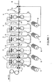
- FIG. 1 schematically represents a tandem rolling installation equipped with a thickness and traction regulation system according to the prior art.
- Figure 2 schematically shows a tandem rolling plant equipped with a thickness and traction control system according to the invention.
- Figure 3 schematically illustrates the distribution of motor currents of a tandem rolling plant according to the prior art.
- FIG. 1 diagrammatically shows the assembly of a tandem rolling plant, comprising five mill stands identified from 1 to 5.
- Such an installation provided, for example for cold rolling of sheets, operates in continuous, and is associated with an input traction device.
- Each rolling mill stand for example of the quarto type, comprises two working rolls T, T 'defining an air gap for passing the product to be rolled B and bearing on two support rolls S, S' between which a rolling force is applied between clamping means such as hydraulic cylinders 11,21,31,41,51.
- a rotating drive means such as an electric motor 12, 22, 32, 42, 52 applies, directly or indirectly, a rolling torque on at least one of the working rolls T, T '.
- the force and the rolling torque are a function of the nature of the product to be rolled, as well as the reduction in thickness to be achieved in each cage.
- the thickness of the product is kept constant at the exit of the cage 1.
- a thickness gauge 13 which will ensure this function by acting on the hydraulic clamping 11. It is also possible to improve this regulation by measuring the gross thickness h o of the band B at the inlet of the installation using another thickness gauge 13 ' installed at the entrance of the cage 1 and also acting on the hydraulic clamping 11 thereof.
- a rolling pattern established in advance allows, according to the characteristics of the product to be rolled and the possibilities of the installation, to distribute the reduction in thickness between the different cages and the staggering of the speeds which in results in order to respect the law of conservation of the masses.
- a control system allows, from the indications given by tensiometers 15, 25, 35, 45 installed at the output, respectively, cages 1, 2, 3, 4 to act on the hydraulic clamping means. , respectively 21, 31, 41, 51 of the following stands 2, 3, 4, 5 in order to correct the reduction in thickness and, consequently, the applied torque, so as to maintain a constant traction in each space 10, 20, 30, 40 between two successive cages, without modifying the ratio between the drive speeds of the respective cylinders.
- the tension meter 15 installed at the outlet of the cage 1 acts on the hydraulic clamping 21 of the cage 2
- the tension meter 25 installed at the outlet of the cage 2 acts on the hydraulic clamping 31 of the cage 3 and so on. It is therefore ensured that at each instant the speed of the band at the entrance of a cage is equal to the speed of the band at the exit of the previous cage.
- the preset system determines, according to the rolling scheme, the reduction in thickness to be performed in each cage and the corresponding motor speed to satisfy equation (1).
- the tension meter 15 installed in the inter-cage space 10 at the outlet of the cage 1 acts on the hydraulic clamping 21 of the cage 2
- the tension meter 25 installed in the space 20 at the outlet of the cage 2 acts on the hydraulic clamping 31 of the cage 3 and so on. Thanks to this traction control, at each instant the speed of the band at the entrance of a cage is maintained equal to the speed of the band at the exit of the previous cage.
- the thickness regulation can be ensured, in a conventional manner, by means of a thickness gauge 53 placed at the outlet 50 of the last cage 5 and acting on the speed V5 of the motor 52 or, sometimes, the motor 42 of the cage 4.
- Such a presetting system may consist simply of presetting tables indicating the intermediate thicknesses for each cage, but may also use a mathematical model capable of calculating the intermediate thicknesses h i * depending on the characteristics of the product to roll, from databases periodically updated by measurements on the rolling mill.
- equation (2) only makes it possible to adjust the speeds in relative value with respect to each other.
- the presetting system determines all the thickness instructions h i * according to the characteristics of the product to be rolled and the power available on them. rolling mill cages, with a certain degree of optimization that depends on the performance of the mathematical model used.
- the part of the control system of a tandem mill that manages all speeds around that of a cage taken as a pivot and allows control of acceleration and deceleration ramps is commonly called the "master speed”.
- a final control of the thickness is provided by the gauge 53 installed at the outlet of the cage 5, so as to correct the residual errors by changing the speed of the last cage of the rolling mill, or those of the last two cages.
- the invention solves this problem by achieving, at each instant, a dynamic balancing, between all the cages, couples to be applied by the motors.
- h i * the thickness of the band at the exit of the cage i corresponding to the set value of the reduction rate assigned to the cage i by the presetting system
- h i the value of the actual output thickness of the cage i.
- the idea of the invention is to reduce the rate of reduction of the overloaded cage in real time by modifying the speeds of the cages so as to change, by a device acting in a closed loop, all the values h i * without disturbing the maintaining at a constant value of the outlet thickness h 5. If we consider the example given in Figure 3, it is possible to reduce the reduction of the cage 3, increasing the output thickness h 3 *. Therefore, to maintain constant final thickness h 5 at the output 50 of the installation, it is necessary to request more reduction in the cage 4 but, precisely, it has available power. This results in a balancing of the currents by a transfer of power on the cages located downstream of the overloaded cage.
- a decrease in the speed setpoint of the cage 3 thus causes an increase in the output thickness h 3 and, consequently, a reduction in the torque to be applied by the motor 13, which makes it possible to achieve the desired effect.
- this potential thickness defect can be compensated by anticipating it by creating it in advance by simultaneous shifting of the stands 1 and 2, in the example chosen.
- the thickness h 3 has increased and, when the speed of the cage 3 is simultaneously lowered by restoring the speeds of the cages 1 and 2 to their initial value, the an increased value of h 3 is maintained and the flow rate h 3 V 3 is constant at the inlet of the cage 4.
- the thickness h 4 is thus kept constant and the outlet thickness h 5 .
- the potential thickness defect resulting from this instantaneous variation of the speed can be compensated by anticipation so as to keep the output thickness h 5 constant, thanks to the method of the invention which makes it possible to control in real time and during the transient interval, instantaneous variations in the thickness, by means of a temporary reverse modification of the speeds of the cages situated upstream of the overloaded cage.
- Equations (2) show that this result can be obtained by increasing the speed of the cage 2. Indeed, since the thickness h 1 at the exit of the cage 1 is kept constant by the regulation of the cage 1, a Increasing the speed of cage 2 will result in a decrease in thickness h 2 , which is the goal. This increase in the thickness reduction ratio in the cage 2 causes an increase in the power consumed by the engine 12. There is therefore a power transfer on the cages located upstream of the cage with the highest load.
- a decrease in the speed reference V 1 * will therefore induce a decrease in thickness h 2 which is the goal. Then, when the decreased thickness h 2 reaches the cage 3, the thickness monitoring device, working in real time and in a closed loop, makes it possible to increase the speeds of the cages 1 and 2 at the same time to obtain the desired effect. without causing a variation of the thickness h 5 at the exit of the rolling installation.
- an overload in a cage is thus avoided by increasing the speed of the preceding cage and, to compensate for the potential thickness error thus generated, an increase in speed of the cage or cages still upstream.
- the invention thus makes it possible to transfer power from the overloaded cage to all of the upstream cages while maintaining the output thickness constant.
- the method of the invention which operates in real time and is applied to a closed-loop installation, enables the currents of the cage drive motors to be rebalanced at any time by combining the effects of balancing on the upstream cages. with those of balancing on downstream cages, and this for all cages simultaneously.
- the invention also covers a device for implementing the method represented by way of example in FIG. 2.
- This representation is purely schematic since such an installation can make use not only of conventional electronic circuit technologies using elementary circuits. comparators, amplifiers, controllers, themselves including proportional, integral and differential action gain settings, but also to newer digital control technologies based on computers and microprocessors, as long as they allow to act in a closed loop, with sufficiently short response times to perform a real-time action, with respect to the other response times of the other parts of the rolling installation.
- the level 6 of dynamic balancing includes a measurement of the currents consumed by the cage motors by means of current transformers 16, 26, 36, 46, 56.
- the dynamic balancing system 6 also contains comparison circuits capable of selecting at each moment the most loaded cage, as well as the transfer function and the gains necessary for the conversion of the load differences into a variation of the thickness instructions. , which will be the new references of thickness h i * cages leading, in steady state, to the equilibrium of currents.
- the circuit 6 will generate the variations necessary to control inter-cage thicknesses, using controllers with proportional gain adjustment, integral and differential, so as to reduce the reduction rates of the most loaded cages in the manner described in the process of the invention.
- the thickness wafer 7 comprises the circuits necessary for the transformation of the inter-cage thickness variations into speed commands of the drive motors, as well as those of the management of the inter-cage thicknesses. transients and, in particular, the system for monitoring the advance of the B-band in the rolling mill.
- the control of the transients 7 will develop the transient and anticipatory variations of cage speed that will allow the balancing of currents, without causing even transient variation of the output thickness. All of these circuits act in real time, in regulation and in a closed loop between the measurement of the differences of the currents of the motors, taken as a sort of error signal at the input of the loop, and the variations of setpoints of the speeds of the drive motors, which constitute the output signals.
- Such a device, according to the invention, for balancing the currents of the drive motors operating in real time and in a closed loop can be adapted to any device for regulating the output thickness and is an integral part of it. this.
- the invention is not limited to the embodiment which has just been described as a simple example and can be applied to any set of rolling stands operating in tandem and comprising at least two successive cages.
- the invention is not limited to cold rolling and can also be applied to a tandem hot rolling mill such as the finishing train of a hot band train.
- the AGC control system that has been described briefly can be of any type allowing control of the final thickness of the rolled product. Indeed, because the invention is based on the respect of the law of "mass flow", it would be possible to imagine variations in the operation of the thickness regulation.
Landscapes
- Engineering & Computer Science (AREA)
- Mechanical Engineering (AREA)
- Control Of Metal Rolling (AREA)
Claims (19)
- Regelverfahren zum Regeln der Enddicke eines gewalzten Produkts (B) am Ausgang einer Walzanlage, die mindestens zwei Ständer (1-5) aufweist, die im Tandem funktionieren und jeweils einen Teil der durch Durchlaufen des Produkts zwischen zwei Arbeitszylindern (T, T') zu verwirklichenden globalen Dickenverringerung bestimmen, wobei jeder Ständer mit Mitteln (11-51) zum Anlegen einer einstellbaren Spannkraft zwischen den Arbeitszylindern und mit Antriebsmitteln (12-52) zum Anlegen auf die Arbeitszylinder eines Drehantriebsmoments mit einer einstellbaren Drehzahl verbunden ist, wobei die Anlage mit einem allgemeinen System zum Steuern der Drehzahlen der verschiedenen Ständer verbunden ist, das eine allmähliche Steigerung der Drehzahl der Zylinder in Abhängigkeit von der allmählichen Variation der Dicke von einem Ständer zum nächsten bestimmt, und mit einer Regelvorrichtung der Dickenreduzierung und der Spannung des Produkts (B) in jedem Raum (10, 20, 30, 40) zwischen zwei aufeinander folgenden Ständern, dadurch gekennzeichnet, dass die Regelvorrichtung in Echtzeit ein dynamisches Ausgleichen der angelegten Momente auf die Arbeitszylinder (T, T') zwischen den verschiedenen Ständern (1-5) verwirklicht, ohne die Enddicke (h5) des Produkts (B) am Ausgang der Anlage merklich zu stören.
- Verfahren nach Anspruch 1, dadurch gekennzeichnet, dass die Regelvorrichtung eine Variation der Walzdrehzahl in mindestens einem der Ständer (3) steuert und die Verteilung der Dickenverringerung und Abstufung der Drehzahlen zwischen den verschiedenen Ständern (1-5) entsprechend ändert, um die Kraft, die für das Antreiben des Produkts (3) mit einer gegebenen Drehzahl am Ausgang der Anlage mit Halten der Enddicke h5 auf einem bestimmten Wert anzulegen ist, auf alle An- triebsmittel (12-52) zu verteilen.
- Verfahren nach einem der Ansprüche 1 und 2, bei dem die globale Dickenverringerung (h0-h5), die zwischen dem Eingang und dem Ausgang der Anlage auszuführen ist, gemäß einem Walzschema von einem Voreinstellsystem verteilt wird, das die von jedem Ständer (1-6) durchzuführende Dickenverringerung und das korrelative Abstufen der Drehzahlen (V1-V5) der Arbeitszylinder bestimmt, dadurch gekennzeichnet, dass man in jedem Augenblick die Last erfasst, die in jedem Ständer (1-5) an die Mittel (12-52) zum Antreiben in Drehung der Arbeitszylinder für das Erzielen der von dem Walzschema festgelegten Drehzahl auferlegt wird, und dass man die Dickenverringerung, die dem am stärksten belasteten Zylinder (3) zugewiesen ist, reduziert, um ein dynamisches Ausgleichen der Lasten auszuführen, die an die verschiedenen ständer angelegt werden.
- Verfahren nach Anspruch 3, dadurch gekennzeichnet, dass man zum Verringern der Dickenverringerung, die dem am stärksten belasteten Ständer zugewiesen ist, die Drehzahl der Zylinder des Ständers im Vergleich zu der von dem Walzschema festgelegten Drehzahl verringert.
- Verfahren nach Anspruch 4, bei dem die Verringerung der Drehzahl des am stärksten belasteten Ständers (3) eine automatische Verringerung der Drehzahl des nächsten Ständers (4) bestimmt der einen Dickenfehler am Ausgang der Auslage während der Vorlaufübergangsperiode des Produkts in dem Zwischenständerraum verursachen kann, dadurch gekennzeichnet, dass dieser potenzielle Dickenfehler durch Vorwegnahme ausgeglichen wird, indem eine Variation in umgekehrte Richtung der Drehzahl aller Ständer (1, 2), die stromaufwärts des am stärksten belasteten Ständers (3) liegen, gesteuert wird, die die Dickenverringerung verringern kann, die von den stromaufwärtigen Ständern (1, 2) ausgeführt wird, um einen Lasttransfer auf die stromabwärtigen Ständer (4, 5) des am stärksten belasteten Ständers (3) auszuführen.
- Verfahren nach Anspruch 3, dadurch gekennzeichnet, dass man zum Verringern der von dem am stärksten belasteten Ständer (3) durchzuführenden Dickenverringerung die Walzdrehzahl in dem vorhergehenden Ständer (2), der unmittelbar stromaufwärts liegt, steigert, um die Dicke des Produkts (B) vor seiner Ankunft in dem am stärksten belasteten Ständer (3) zu verringern.
- Verfahren nach Anspruch 6, bei dem die Steigerung der Drehzahl in dem vorhergehenden Ständer (2) eine automatische Steigerung der Drehzahl in dem am stärksten belasteten Ständer (3) bestimmt, die einen Dickenfehler am Ausgang der Anlage während einer Vorlaufübergangsperiode des Produkts von dem vorhergehenden Ständer (2) zu dem am stärksten belasteten Ständer (3) verursachen kann, dadurch gekennzeichnet, dass dieser potenzielle Dickenfehler durch Vorwegnahme ausgeglichen wird, indem eine Steigerung der Walzdrehzahl in mindestens einem Ständer (1), der noch stromaufwärts des vorhergehenden Ständers (2) liegt, so gesteuert wird, dass ein Lasttransfer auf die Einheit der Ständer (1, 2) ausgeführt wird, die sich stromaufwärts des am stärksten belasteten Ständers (3) befinden, indem die in jedem dieser ausgeführte Dickenverringerung gesteigert wird.
- Verfahren nach einem der Ansprüche 5 und 7, dadurch gekennzeichnet, dass man eine ständige Mitverfolgung der Dickenvariation des Produkts im Laufe seines Vorlaufs von dem ersten (1) zu dem letzten (5) Ständer der Anlage durchführt, um eine Drehzahlvariation bestimmter Ständer zu steuern, die einen potenziellen Dickenfehler während einer Übergangsperiode ausgleichen kann, die der Zeit für den Vorlauf zwischen zwei aufeinander folgenden Ständern jeweils stromaufwärts und stromabwärts der Dickenvariation entspricht, die sich aus einer Drehzahlvariation des stromaufwärtigen Ständers ergibt, um die Dicke (h5) des Produkts am Ausgang des letzten Ständers (5) der Anlage jederzeit konstant zu halten.
- Verfahren nach Anspruch 8, dadurch gekennzeichnet, dass man nach dem Erfassten des am stärksten belasteten Ständers (3 Drehzahlvariationen auf den zwei Ständereinheiten kombiniert, die jeweils stromaufwärts (1, 2) und stromabwärts (4, 5) des am stärksten belasteten Ständers (3) liegen, indem man einen Lasttransfert zu bestimmten Ständern der stromaufwärtigen (1, 2) und stromabwärtigen (4, 5) Einheiten gemäß der erfassten Last erzeugt, um die Lasten auf allen Ständern (1-5) der Anlage auszugleichen und gleichzeitig die Enddicke (h5) des Produkts (B) anderen Ausgang konstant zu halten.
- Verfahren nach einem der vorhergehenden Ansprüche, dadurch gekennzeichnet, dass nach dem Ausführen des dynamischen Ausgleichens der an alle Ständer (1-5) angelegten Lasten die Walzdrehzahl in einem der Ständer gesteigert wird und das Regelsystem die Drehzahlen der anderen Ständer entsprechend variieren lässt, um die Drehzahl des Produkts (B am Ausgang der Anlage ohne Stören der Enddicke und unter Beibehalten des dynamischen Ausgleichs zwischen allen Ständern zu steigern.
- Verfahren nach Anspruch 10, dadurch gekennzeichnet, dass die Steigerung der allgemeinen Drehzahl der Anlage einen Gewinn darstellt, der bis zu 15% der maximalen Drehzahl gehen kann, die ohne dynamisches Ausgleichen der angelegten Momente erzielt wird.
- Verfahren nach einem der vorhergehenden Ansprüche, bei dem die Antriebsmittel der Zylinder Elektromotoren (12, 22, 32, 42, 52) sind, dadurch gekennzeichnet, dass das Regelsystem einen dynamischen Ausgleich der Ströme ausführt, ohne eine Nennstromstärke in jedem Motor zu überschreiten.
- Vorrichtung zum Regeln der Enddicke (h5) eines gewalzten Produkts (B) am Ausgang einer Tandemwalzanlage, die mindestens zwei Ständer 1-5) aufweist, die voneinander beabstandet sind und die jeweils einen Teil der Dickenverringerung bestimmen, wobei jeder Ständer mindestens zwei Arbeitszylinder (T, T') aufweist, die einen Luftspalt zum Durchgehen des Produkts (B) definieren, Mittel (11-51) zum Anlegen einer einstellbaren Spannkraft zwischen den Arbeitszylindern und Antriebsmittel (12-52) zum Antreiben der Zylinder mit einer einstellbaren Drehzahl, wobei die Anlage mit einem allgemeinen System zum Steuern der Drehzahlen der verschiedenen Ständer verbunden ist, das eine allmähliche Steigerung der Drehzahl der Zylinder in Abhängigkeit von der allmählichen Dickevariation von einem Ständer (i) zum nächsten (i+1) bestimmt, und mit einer Regelvorrichtung zum Reduzieren der Dicke und der Spannung des Produkts (B) in jedem Raum (10-50) zwischen zwei aufeinander folgenden Ständern (1-5), dadurch gekennzeichnet, dass die Regelvorrichtung einen Schaltkreis (6, 7) in geschlossener Schleife zum dynamischen Ausgleichen zwischen den verschiedenen Ständern (1-5) der Momente aufweist, die von den Antriebsmitteln (12-52) jedes Ständers zum Erzielen der gewünschten Enddicke (h5) und zum Beibehalten dieser auf einem im Wesentlichen konstanten Wert angelegt werden.
- Vorrichtung nach Anspruch 13 zum Regeln der Enddicke (h5) des gewalzten Produkts (B) am Ausgang einer Walzanlage, bei der das allgemeine System zum Steuern der Drehzahlen mit einem Voreinstellsystem der Dickenverringerung, die jedem Ständer zugewiesen ist, verbunden ist, das für jeden Ständer (1-5) einen Sollwert (V1*-V5*) bestimmt, der an die Antriebsmittel (12-52) anzuwenden ist, um eine allmähliche Steigerung der Drehzahl herzustellen, die der Dickenvariation von einem Ständer zum nächsten entspricht, dadurch gekennzeichnet, dass der Schaltkreis (6, 7) zum dynamischen Ausgleichen Mittel aufweist, um auf jedem Ständer den Drehzahlsollwert (V1*-V5*) zu korrigieren, der von dem Voreinstellsystem bestimmt wird, so dass die Verteilung der Dickenverringerung auf die verschiedenen Ständer (1-5) geändert wird.
- Regelvorrichtung nach Anspruch 14, dadurch gekennzeichnet, dass der Schaltkreis zum dynamischen Ausgleichen ein Steuermodul (7) der Transienten aufweist, die in der geschlossenen Schleife auf die Antriebsmittel (12-52) der Zylinder einwirken, um durch Vorwegnahme eine zusätzliche Korrektur des Drehzahlsollwerts (V1*-V5*) während einer vorübergehenden Vorlaufperiode des Produkts (B) zwischen einem Ständer (i), dessen Drehzahlsollwert (V3*) korrigiert wurde, und dem darauf folgenden Ständer (i+1) vorzunehmen.
- Regelvorrichtung nach Anspruch 15, dadurch gekennzeichnet, dass das Steuermodul (7) der Transienten mit Mitteln zum ständigen Überwachen der Dickenvariation des Produkts (B) im Laufe des Durchlaufens zwischen dem Eingang und dem Ausgang der Anlage verbunden ist, die die Augenblicke des Anfangs und des Endes der Übergangsperiode bestimmen, während welcher eine zusätzliche Korrektur an dem Drehzahlsollwert (V1*) mindestens eines der Ständer (i) vorgenommen wird.
- Regelvorrichtung nach Anspruch 16, dadurch gekennzeichnet, dass der Schaltkreis (6) zum dynamischen Ausgleichen der Ströme der Motoren und das Modul (7) zum Steuern der Transienten mit einer Ausgangsendstufe für das Steuern der Drehzahlvariationen konzipiert sind, die einen Regler mit integraler und differenzieller Proportionalsteuerung aufweist.
- Walzanlage mit mindestens zwei Ständern (1-5) im Tandembetrieb, ausgestattet mit einstellbaren Spannmitteln (11-51) der Walzzylinder und mit elektrischen. Mitteln (12-52) zum Antreiben der Walzzylinder in Drehung und Mitteln zum Regeln der Ausgangsdicke des Produkts (B) und der Züge zwischen den Ständern eines Voreinstellsystems der Dickenverringerungsrate jedes Ständers und einem allgemeinen Steuersystem der Drehzahlen aller Walzständer (1-5), dadurch gekennzeichnet, dass sie eine Vorrichtung (6, 7) gemäß einem der Ansprüche 13 bis 17 zum Regeln der Enddicke des gewalzten Produkts durch Ausgleichen der Ströme der Antriebsmotoren der Ständer aufweist.
- Walzanlage nach Anspruch 18, dadurch gekennzeichnet, dass die Regelvorrichtung (6, 7) der Enddicke Mittel zum Korrigieren des Drehzahlsollwerts (V1*-V5*), der von dem Voreinstellsystem erstellt wird, mindestens eines der Antriebsmotoren (12-52), aufweist.
Applications Claiming Priority (2)
| Application Number | Priority Date | Filing Date | Title |
|---|---|---|---|
| FR0304583 | 2003-04-11 | ||
| FR0304583A FR2853570B1 (fr) | 2003-04-11 | 2003-04-11 | Procede et dispositif de regulation de l'epaisseur d'un produit lamine |
Publications (2)
| Publication Number | Publication Date |
|---|---|
| EP1466675A1 EP1466675A1 (de) | 2004-10-13 |
| EP1466675B1 true EP1466675B1 (de) | 2006-12-20 |
Family
ID=32865426
Family Applications (1)
| Application Number | Title | Priority Date | Filing Date |
|---|---|---|---|
| EP04300199A Expired - Fee Related EP1466675B1 (de) | 2003-04-11 | 2004-04-08 | Verfahren und Vorrichtung zur Dickenregelung eines gewalzten Produktes |
Country Status (6)
| Country | Link |
|---|---|
| US (1) | US7086260B2 (de) |
| EP (1) | EP1466675B1 (de) |
| JP (1) | JP2005095975A (de) |
| DE (1) | DE602004003734T2 (de) |
| ES (1) | ES2278288T3 (de) |
| FR (1) | FR2853570B1 (de) |
Families Citing this family (17)
| Publication number | Priority date | Publication date | Assignee | Title |
|---|---|---|---|---|
| FR2887480B1 (fr) * | 2005-06-23 | 2007-09-21 | Vai Clecim Soc Par Actions Sim | Procede et dispositif de regulation de l'epaisseur d'un produit lamine en sortie d'une installation de laminage en tandem |
| DE102007031333A1 (de) * | 2007-07-05 | 2009-01-15 | Siemens Ag | Walzen eines Bandes in einer Walzstraße unter Nutzung des letzen Gerüsts der Walzstraße als Zugverringerer |
| DE102007050891A1 (de) * | 2007-10-24 | 2009-04-30 | Siemens Ag | Auf der Streuung einer Istgröße eines Walzguts basierende Adaptierung eines Reglers in einem Walzwerk |
| EP2221121B1 (de) * | 2007-11-02 | 2014-08-13 | Nippon Steel & Sumitomo Metal Corporation | Bandwalzwerk und steuerverfahren dafür |
| US8893537B2 (en) | 2007-11-07 | 2014-11-25 | The Bradbury Company, Inc. | Methods and apparatus to drive material conditioning machines |
| DE102008007057A1 (de) * | 2008-01-31 | 2009-08-13 | Siemens Aktiengesellschaft | Regelverfahren für eine Kaltwalzstraße mit vollständiger Massenflussregelung |
| WO2010049338A2 (de) † | 2008-10-30 | 2010-05-06 | Siemens Aktiengesellschaft | Verfahren zum einstellen einer antriebslast für eine mehrzahl an antrieben einer walzstrasse zum walzen von walzgut, steuer- und/oder regeleinrichtung, speichermedium, programmcode und walzanlage |
| IT1400550B1 (it) * | 2010-06-09 | 2013-06-11 | Danieli Automation Spa | Procedimento e dispositivo per il controllo dimensionale della sezione di un prodotto laminato. |
| CA2814077C (en) | 2010-10-06 | 2017-04-18 | The Bradbury Company, Inc. | Apparatus and methods to increase the efficiency of roll-forming and leveling systems |
| EP2460597A1 (de) * | 2010-12-01 | 2012-06-06 | Siemens Aktiengesellschaft | Verfahren zum Ansteuern einer Tandemwalzstrasse, Steuer- und/oder Regeleinrichtung für eine Tandemwalzstrasse, maschinenlesbarer Programmcode, Speichermedium und Tandemwalzstrasse |
| JP6045420B2 (ja) * | 2013-03-27 | 2016-12-14 | 株式会社日立製作所 | 熱間タンデム圧延ミル制御装置及び熱間タンデム圧延ミルの制御方法 |
| US10363590B2 (en) | 2015-03-19 | 2019-07-30 | Machine Concepts, Inc. | Shape correction leveler drive systems |
| WO2019138908A1 (ja) * | 2018-01-10 | 2019-07-18 | 日本製鉄株式会社 | 形鋼の圧延方法、形鋼の製造ライン及び形鋼の製造方法 |
| US11318474B2 (en) * | 2018-05-14 | 2022-05-03 | Pearson Incorporated | Milling system and method |
| ES2935469T3 (es) | 2018-11-23 | 2023-03-07 | John Cockerill S A | Laminador en frío flexible y método para convertir el mismo |
| IT202000000316A1 (it) * | 2020-01-10 | 2021-07-10 | Danieli Off Mecc | Metodo ed apparato di produzione di prodotti metallici piani |
| CN111545575B (zh) * | 2020-04-30 | 2021-11-05 | 中冶南方工程技术有限公司 | 五机架冷连轧机动态变规格阶段的厚度控制方法 |
Family Cites Families (6)
| Publication number | Priority date | Publication date | Assignee | Title |
|---|---|---|---|---|
| JPS6010810B2 (ja) * | 1975-08-25 | 1985-03-20 | 株式会社日立製作所 | 圧延機の板厚制御方法 |
| JPS6016850B2 (ja) * | 1981-02-06 | 1985-04-27 | 住友金属工業株式会社 | コ−ルドタンデムミルの圧延速度揃速方法 |
| JPS6083711A (ja) * | 1983-10-15 | 1985-05-13 | Mitsubishi Electric Corp | 連続圧延機の負荷配分制御方法 |
| JPS63248505A (ja) * | 1987-03-31 | 1988-10-14 | Kobe Steel Ltd | 圧延制御方法 |
| US5809817A (en) * | 1997-03-11 | 1998-09-22 | Danieli United, A Division Of Danieli Corporation Corporation | Optimum strip tension control system for rolling mills |
| FR2788233B1 (fr) * | 1999-01-11 | 2001-02-23 | Alstom | Procede de regulation des tractions/compressions dans un laminoir multicage a chaud et systeme de commande correspondant |
-
2003
- 2003-04-11 FR FR0304583A patent/FR2853570B1/fr not_active Expired - Fee Related
-
2004
- 2004-03-29 US US10/811,499 patent/US7086260B2/en not_active Expired - Fee Related
- 2004-04-08 ES ES04300199T patent/ES2278288T3/es not_active Expired - Lifetime
- 2004-04-08 EP EP04300199A patent/EP1466675B1/de not_active Expired - Fee Related
- 2004-04-08 DE DE602004003734T patent/DE602004003734T2/de not_active Expired - Lifetime
- 2004-04-12 JP JP2004116875A patent/JP2005095975A/ja active Pending
Also Published As
| Publication number | Publication date |
|---|---|
| EP1466675A1 (de) | 2004-10-13 |
| FR2853570A1 (fr) | 2004-10-15 |
| US7086260B2 (en) | 2006-08-08 |
| ES2278288T3 (es) | 2007-08-01 |
| US20040221633A1 (en) | 2004-11-11 |
| JP2005095975A (ja) | 2005-04-14 |
| DE602004003734D1 (de) | 2007-02-01 |
| FR2853570B1 (fr) | 2005-07-01 |
| DE602004003734T2 (de) | 2007-10-04 |
Similar Documents
| Publication | Publication Date | Title |
|---|---|---|
| EP1466675B1 (de) | Verfahren und Vorrichtung zur Dickenregelung eines gewalzten Produktes | |
| EP1907144B1 (de) | Verfahren und vorrichtung zur steuerung der dicke eines walzproduktes am ausgang eines tandem-walzwerks | |
| EP3086889B1 (de) | Heisswalzverfahren, heisswalzwerk und computerprogramm zur durchführung eines solchen verfahrens | |
| EP1827723A1 (de) | Regulierung der ebenheit eines metallbands am ausgang eines walzenständers | |
| EP0988903B1 (de) | Verfahren zum Walzen eines Metallproduktes | |
| EP1020240B1 (de) | Verfahren zur Zug-/Druckregelung in einem Vielständer-Warmwalzwerk und entsprechendes Regelungssystem | |
| CA2259110C (fr) | Procede de pilotage d'une operation d'ecrouissage en continu d'une bande metallique | |
| EP2303482B1 (de) | Verfahren zum wechseln einer walze in einem walzwerk für ein kontinuierlich laufendes stahlband | |
| EP1996347B1 (de) | Verfahren zum walzen eines blechbands | |
| EP0466570B1 (de) | Umkehrbares Walzverfahren | |
| US4691546A (en) | Rolling mill control for tandem rolling | |
| EP2172282B1 (de) | Verfahren zur Steuerung des Walzens eines Blechbandes | |
| EP0000454B1 (de) | Verfahren zum Steuern der Walzgutspannung zwischen aufeinanderfolgenden Walzgerüsten beim Warmwalzen von dickem Walzgut. | |
| EP3600708B1 (de) | Walzgerüst, das mit einer kontrollvorrichtung für die walzstabilität ausgerüstet ist, und entsprechende methode | |
| EP0560688A1 (de) | Regelungsvorrichtung eines Kaltbearbeitungswerkzeuges zum Nachwalzen von Blech | |
| EP0867245B1 (de) | Methode zur Regelung der Rollen-Rotationsgeschwindigkeit beim Rollengiessverfahren | |
| US6305206B1 (en) | Reversible rolling method and reversible rolling system | |
| FR2493192A1 (fr) | Procede de mesure de la tension d'un produit en cours de laminage, installation pour la mise en oeuvre de ce procede, et leur application a la synchronisation des cages d'une ligne de laminage a postes multiples | |
| BE673402A (de) | ||
| Murakami et al. | Pass Schedule Optimization for a Tandem Cold Mill | |
| FR2464106A1 (fr) | Dispositif pour la regulation automatique de la forme de bandes en cours de laminage | |
| BE511025A (de) | ||
| FR2473915A1 (fr) | Procede et dispositif de regulation de l'epaisseur d'un lamine | |
| CH266688A (fr) | Procédé de laminage d'un fil métallique et dispositif pour la mise en oeuvre de ce procédé. |
Legal Events
| Date | Code | Title | Description |
|---|---|---|---|
| PUAI | Public reference made under article 153(3) epc to a published international application that has entered the european phase |
Free format text: ORIGINAL CODE: 0009012 |
|
| AK | Designated contracting states |
Kind code of ref document: A1 Designated state(s): AT BE BG CH CY CZ DE DK EE ES FI FR GB GR HU IE IT LI LU MC NL PL PT RO SE SI SK TR |
|
| AX | Request for extension of the european patent |
Extension state: AL HR LT LV MK |
|
| 17P | Request for examination filed |
Effective date: 20050413 |
|
| AKX | Designation fees paid |
Designated state(s): DE ES FR GB IT SE |
|
| GRAP | Despatch of communication of intention to grant a patent |
Free format text: ORIGINAL CODE: EPIDOSNIGR1 |
|
| GRAS | Grant fee paid |
Free format text: ORIGINAL CODE: EPIDOSNIGR3 |
|
| GRAA | (expected) grant |
Free format text: ORIGINAL CODE: 0009210 |
|
| AK | Designated contracting states |
Kind code of ref document: B1 Designated state(s): DE ES FR GB IT SE |
|
| REG | Reference to a national code |
Ref country code: GB Ref legal event code: FG4D Free format text: NOT ENGLISH |
|
| REF | Corresponds to: |
Ref document number: 602004003734 Country of ref document: DE Date of ref document: 20070201 Kind code of ref document: P |
|
| REG | Reference to a national code |
Ref country code: SE Ref legal event code: TRGR |
|
| GBT | Gb: translation of ep patent filed (gb section 77(6)(a)/1977) |
Effective date: 20070315 |
|
| REG | Reference to a national code |
Ref country code: ES Ref legal event code: FG2A Ref document number: 2278288 Country of ref document: ES Kind code of ref document: T3 |
|
| PLBE | No opposition filed within time limit |
Free format text: ORIGINAL CODE: 0009261 |
|
| STAA | Information on the status of an ep patent application or granted ep patent |
Free format text: STATUS: NO OPPOSITION FILED WITHIN TIME LIMIT |
|
| 26N | No opposition filed |
Effective date: 20070921 |
|
| PGFP | Annual fee paid to national office [announced via postgrant information from national office to epo] |
Ref country code: ES Payment date: 20120524 Year of fee payment: 9 |
|
| PGFP | Annual fee paid to national office [announced via postgrant information from national office to epo] |
Ref country code: DE Payment date: 20130620 Year of fee payment: 10 Ref country code: SE Payment date: 20130411 Year of fee payment: 10 Ref country code: GB Payment date: 20130415 Year of fee payment: 10 |
|
| PGFP | Annual fee paid to national office [announced via postgrant information from national office to epo] |
Ref country code: FR Payment date: 20130430 Year of fee payment: 10 Ref country code: IT Payment date: 20130417 Year of fee payment: 10 |
|
| REG | Reference to a national code |
Ref country code: DE Ref legal event code: R119 Ref document number: 602004003734 Country of ref document: DE |
|
| REG | Reference to a national code |
Ref country code: SE Ref legal event code: EUG |
|
| GBPC | Gb: european patent ceased through non-payment of renewal fee |
Effective date: 20140408 |
|
| REG | Reference to a national code |
Ref country code: FR Ref legal event code: ST Effective date: 20141231 |
|
| REG | Reference to a national code |
Ref country code: DE Ref legal event code: R119 Ref document number: 602004003734 Country of ref document: DE Effective date: 20141101 |
|
| PG25 | Lapsed in a contracting state [announced via postgrant information from national office to epo] |
Ref country code: SE Free format text: LAPSE BECAUSE OF NON-PAYMENT OF DUE FEES Effective date: 20140409 Ref country code: DE Free format text: LAPSE BECAUSE OF NON-PAYMENT OF DUE FEES Effective date: 20141101 Ref country code: GB Free format text: LAPSE BECAUSE OF NON-PAYMENT OF DUE FEES Effective date: 20140408 |
|
| PG25 | Lapsed in a contracting state [announced via postgrant information from national office to epo] |
Ref country code: FR Free format text: LAPSE BECAUSE OF NON-PAYMENT OF DUE FEES Effective date: 20140430 |
|
| PG25 | Lapsed in a contracting state [announced via postgrant information from national office to epo] |
Ref country code: IT Free format text: LAPSE BECAUSE OF NON-PAYMENT OF DUE FEES Effective date: 20140408 |
|
| REG | Reference to a national code |
Ref country code: ES Ref legal event code: FD2A Effective date: 20151204 |
|
| PG25 | Lapsed in a contracting state [announced via postgrant information from national office to epo] |
Ref country code: ES Free format text: LAPSE BECAUSE OF NON-PAYMENT OF DUE FEES Effective date: 20140409 |