EP0987501A2 - Klimaanlage - Google Patents
Klimaanlage Download PDFInfo
- Publication number
- EP0987501A2 EP0987501A2 EP99307215A EP99307215A EP0987501A2 EP 0987501 A2 EP0987501 A2 EP 0987501A2 EP 99307215 A EP99307215 A EP 99307215A EP 99307215 A EP99307215 A EP 99307215A EP 0987501 A2 EP0987501 A2 EP 0987501A2
- Authority
- EP
- European Patent Office
- Prior art keywords
- refrigerant
- opening
- electric motor
- port
- valve
- Prior art date
- Legal status (The legal status is an assumption and is not a legal conclusion. Google has not performed a legal analysis and makes no representation as to the accuracy of the status listed.)
- Withdrawn
Links
Images


Classifications
-
- F—MECHANICAL ENGINEERING; LIGHTING; HEATING; WEAPONS; BLASTING
- F24—HEATING; RANGES; VENTILATING
- F24F—AIR-CONDITIONING; AIR-HUMIDIFICATION; VENTILATION; USE OF AIR CURRENTS FOR SCREENING
- F24F1/00—Room units for air-conditioning, e.g. separate or self-contained units or units receiving primary air from a central station
-
- F—MECHANICAL ENGINEERING; LIGHTING; HEATING; WEAPONS; BLASTING
- F04—POSITIVE - DISPLACEMENT MACHINES FOR LIQUIDS; PUMPS FOR LIQUIDS OR ELASTIC FLUIDS
- F04C—ROTARY-PISTON, OR OSCILLATING-PISTON, POSITIVE-DISPLACEMENT MACHINES FOR LIQUIDS; ROTARY-PISTON, OR OSCILLATING-PISTON, POSITIVE-DISPLACEMENT PUMPS
- F04C18/00—Rotary-piston pumps specially adapted for elastic fluids
- F04C18/02—Rotary-piston pumps specially adapted for elastic fluids of arcuate-engagement type, i.e. with circular translatory movement of co-operating members, each member having the same number of teeth or tooth-equivalents
- F04C18/0207—Rotary-piston pumps specially adapted for elastic fluids of arcuate-engagement type, i.e. with circular translatory movement of co-operating members, each member having the same number of teeth or tooth-equivalents both members having co-operating elements in spiral form
- F04C18/0215—Rotary-piston pumps specially adapted for elastic fluids of arcuate-engagement type, i.e. with circular translatory movement of co-operating members, each member having the same number of teeth or tooth-equivalents both members having co-operating elements in spiral form where only one member is moving
-
- F—MECHANICAL ENGINEERING; LIGHTING; HEATING; WEAPONS; BLASTING
- F04—POSITIVE - DISPLACEMENT MACHINES FOR LIQUIDS; PUMPS FOR LIQUIDS OR ELASTIC FLUIDS
- F04C—ROTARY-PISTON, OR OSCILLATING-PISTON, POSITIVE-DISPLACEMENT MACHINES FOR LIQUIDS; ROTARY-PISTON, OR OSCILLATING-PISTON, POSITIVE-DISPLACEMENT PUMPS
- F04C23/00—Combinations of two or more pumps, each being of rotary-piston or oscillating-piston type, specially adapted for elastic fluids; Pumping installations specially adapted for elastic fluids; Multi-stage pumps specially adapted for elastic fluids
- F04C23/008—Hermetic pumps
-
- F—MECHANICAL ENGINEERING; LIGHTING; HEATING; WEAPONS; BLASTING
- F04—POSITIVE - DISPLACEMENT MACHINES FOR LIQUIDS; PUMPS FOR LIQUIDS OR ELASTIC FLUIDS
- F04C—ROTARY-PISTON, OR OSCILLATING-PISTON, POSITIVE-DISPLACEMENT MACHINES FOR LIQUIDS; ROTARY-PISTON, OR OSCILLATING-PISTON, POSITIVE-DISPLACEMENT PUMPS
- F04C29/00—Component parts, details or accessories of pumps or pumping installations, not provided for in groups F04C18/00 - F04C28/00
- F04C29/04—Heating; Cooling; Heat insulation
- F04C29/045—Heating; Cooling; Heat insulation of the electric motor in hermetic pumps
-
- F—MECHANICAL ENGINEERING; LIGHTING; HEATING; WEAPONS; BLASTING
- F24—HEATING; RANGES; VENTILATING
- F24F—AIR-CONDITIONING; AIR-HUMIDIFICATION; VENTILATION; USE OF AIR CURRENTS FOR SCREENING
- F24F3/00—Air-conditioning systems in which conditioned primary air is supplied from one or more central stations to distributing units in the rooms or spaces where it may receive secondary treatment; Apparatus specially designed for such systems
- F24F3/001—Air-conditioning systems in which conditioned primary air is supplied from one or more central stations to distributing units in the rooms or spaces where it may receive secondary treatment; Apparatus specially designed for such systems in which the air treatment in the central station takes place by means of a heat-pump or by means of a reversible cycle
-
- F—MECHANICAL ENGINEERING; LIGHTING; HEATING; WEAPONS; BLASTING
- F25—REFRIGERATION OR COOLING; COMBINED HEATING AND REFRIGERATION SYSTEMS; HEAT PUMP SYSTEMS; MANUFACTURE OR STORAGE OF ICE; LIQUEFACTION SOLIDIFICATION OF GASES
- F25B—REFRIGERATION MACHINES, PLANTS OR SYSTEMS; COMBINED HEATING AND REFRIGERATION SYSTEMS; HEAT PUMP SYSTEMS
- F25B13/00—Compression machines, plants or systems, with reversible cycle
-
- F—MECHANICAL ENGINEERING; LIGHTING; HEATING; WEAPONS; BLASTING
- F25—REFRIGERATION OR COOLING; COMBINED HEATING AND REFRIGERATION SYSTEMS; HEAT PUMP SYSTEMS; MANUFACTURE OR STORAGE OF ICE; LIQUEFACTION SOLIDIFICATION OF GASES
- F25B—REFRIGERATION MACHINES, PLANTS OR SYSTEMS; COMBINED HEATING AND REFRIGERATION SYSTEMS; HEAT PUMP SYSTEMS
- F25B31/00—Compressor arrangements
- F25B31/02—Compressor arrangements of motor-compressor units
- F25B31/026—Compressor arrangements of motor-compressor units with compressor of rotary type
-
- F—MECHANICAL ENGINEERING; LIGHTING; HEATING; WEAPONS; BLASTING
- F25—REFRIGERATION OR COOLING; COMBINED HEATING AND REFRIGERATION SYSTEMS; HEAT PUMP SYSTEMS; MANUFACTURE OR STORAGE OF ICE; LIQUEFACTION SOLIDIFICATION OF GASES
- F25B—REFRIGERATION MACHINES, PLANTS OR SYSTEMS; COMBINED HEATING AND REFRIGERATION SYSTEMS; HEAT PUMP SYSTEMS
- F25B2313/00—Compression machines, plants or systems with reversible cycle not otherwise provided for
- F25B2313/027—Compression machines, plants or systems with reversible cycle not otherwise provided for characterised by the reversing means
- F25B2313/0272—Compression machines, plants or systems with reversible cycle not otherwise provided for characterised by the reversing means using bridge circuits of one-way valves
-
- F—MECHANICAL ENGINEERING; LIGHTING; HEATING; WEAPONS; BLASTING
- F25—REFRIGERATION OR COOLING; COMBINED HEATING AND REFRIGERATION SYSTEMS; HEAT PUMP SYSTEMS; MANUFACTURE OR STORAGE OF ICE; LIQUEFACTION SOLIDIFICATION OF GASES
- F25B—REFRIGERATION MACHINES, PLANTS OR SYSTEMS; COMBINED HEATING AND REFRIGERATION SYSTEMS; HEAT PUMP SYSTEMS
- F25B2313/00—Compression machines, plants or systems with reversible cycle not otherwise provided for
- F25B2313/027—Compression machines, plants or systems with reversible cycle not otherwise provided for characterised by the reversing means
- F25B2313/02741—Compression machines, plants or systems with reversible cycle not otherwise provided for characterised by the reversing means using one four-way valve
Definitions
- the present invention relates to an air conditioner and, more particularly, to a compressor used for reversible refrigerant circuit (reversible refrigeration cycle) capable of performing the switching between cooling operation and heating operation.
- An air conditioner has a refrigerant circuit in which an outdoor-side heat exchanger, an expansion valve, and an indoor-side heat exchanger are connected with a compressor in a loop form by refrigerant pipes via a four-way switching valve.
- a refrigerant circuit in which an outdoor-side heat exchanger, an expansion valve, and an indoor-side heat exchanger are connected with a compressor in a loop form by refrigerant pipes via a four-way switching valve.
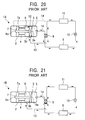
- FIG. 20 shows a refrigerant circuit using an internal high pressure type compressor 1A
- FIG. 21 shows a refrigerant circuit using an internal low pressure type compressor 1B.
- the basic configurations of the compressors 1A and 1B are the same.
- the compressor of either type has a cylindrical enclosed vessel 2, and the enclosed vessel 2 contains a refrigerant compressing section 3 and an electric motor 4.
- the refrigerant compressing section 3 being of a scroll type, has a compression chamber formed by engaging a fixed scroll having a spiral wrap on an end plate with an orbiting scroll driven by the electric motor 4.
- the interior of the enclosed vessel 2 is divided into two chambers by the end plate on the side of the fixed scroll in the refrigerant compressing section 3.
- One of these two chambers is a refrigerant discharge chamber 5 provided on the side of a discharge port 3a of the refrigerant compressing section 3.
- the other is an electric motor chamber 6 in which the electric motor 4 is contained.
- the electric motor chamber 6 is provided with a bearer plate 7 which pivotally supports a driving shaft 4a of the electric motor 4.
- a subsidiary electric motor chamber 6a is formed on the side opposite to the refrigerant discharge chamber 5 of the electric motor chamber 6 by the bearer plate 7.
- the bearer plate 7 is formed with an arbitrary number of refrigerant flowing holes 7a.
- Either of the compressors 1A and 1B is connected, via a four-way switching valve 8, with a heat exchanging circuit in which an outdoor-side heat exchanger 9, an expansion valve (or a capillary tube) 10, and an indoor-side heat exchanger 11 are connected in a loop form by refrigerant pipes.
- the configurations of the internal high pressure type compressor 1A and the internal low pressure type compressor 1B differ in the following respects: That is, in the internal high pressure type compressor 1A shown in FIG. 20, the refrigerant discharge chamber 5 communicates with the electric motor chamber 6 via a communicating path 12, and a suction pipe 13 for low-pressure refrigerant drawn from the four-way switching valve 8 is directly connected to a suction port 3b of the refrigerant compressing section 3.
- the refrigerant discharge chamber 5 and the electric motor chamber 6 are independent of each other.
- the suction port 3b of the refrigerant compressing section 3 is opened on the side of the electric motor chamber 6, and the suction pipe 13 drawn from the four-way switching valve 8 is connected to the electric motor chamber 6.
- FIG. 20 shows a state at the time of cooling operation using the internal high pressure type compressor 1A.
- a low-pressure refrigerant from the indoor-side heat exchanger 11 is sucked into the refrigerant compressing section 3 through the suction pipe 13.
- the refrigerant is discharged into the refrigerant discharge chamber 5 as a high-temperature high-pressure refrigerant gas.
- This high-temperature high-pressure refrigerant gas is supplied to the outdoor-side heat exchanger 9 through a discharge pipe 14 for high-pressure refrigerant and the four-way switching valve 8.
- some of the high-temperature high-pressure refrigerant gas flows into the electric motor chamber 6 through the communication path 12. Thereby, the compressor 1A is classified as the internal high pressure type.
- the discharge pipe 14 for high-pressure refrigerant is connected to the side of the subsidiary electric motor chamber 6a, not to the refrigerant discharge chamber 5, as indicated by the chain line in FIG. 20 so that a high-pressure refrigerant is introduced from the subsidiary electric motor chamber 6a to the four-way switching valve 8.
- the four-way switching valve 8 is turned 90 degrees from the state shown in FIG. 20, so that the discharge pipe 14 for high-pressure refrigerant is connected to the indoor-side heat exchanger 11, and the suction pipe 13 for low-pressure refrigerant is connected to the outdoor-side heat exchanger 9.
- FIG. 21 shows a state at the time of heating operation using the internal low pressure type compressor 1B.
- the low-pressure refrigerant from the outdoor-side heat exchanger 9 flows into the electric motor chamber 6 through the suction pipe 13, so that the interior thereof becomes low in pressure.
- the low-pressure refrigerant is sucked into the refrigerant compressing section 3 through the suction port 3b.
- the refrigerant is discharged into the refrigerant discharge chamber 5 as a high-temperature high-pressure refrigerant gas, and is supplied to the indoor-side heat exchanger 11 through the discharge pipe 14 and the four-way switching valve 8.
- the four-way switching valve 8 is turned 90 degrees from the state shown in FIG. 21, so that the discharge pipe 14 for high-pressure refrigerant is connected to the outdoor-side heat exchanger 9, and the suction pipe 13 for low-pressure refrigerant is connected to the indoor-side heat exchanger 11.
- an object of introducing the refrigerant into the electric motor chamber is to prevent overheat of the electric motor, and these two types have advantages and disadvantages as described below.
- the lubricating oil can be separated from the refrigerant gas in the electric motor chamber, the lubricating oil is positively supplied into the compressor, by which good sealing can be provided between rubbing portions of the fixed scroll and the orbiting scroll in the refrigerant compressing section. Also, by making the interior of the electric motor chamber high in pressure, a thrust force applied to the orbiting scroll can be controlled easily, and the load on the electric motor can be decreased. Accordingly, the power consumption can be lowered.
- the internal high pressure type since the temperature of the enclosed vessel is higher than the ambient temperature at the time of cooling operation, the heat dissipation amount is increased, so that the cooling capacity can be increased.
- the internal high pressure type is disadvantageous in terms of heating capacity because the amount of heat dissipating from the enclosed vessel is large.
- the internal low pressure type since the temperature of the enclosed vessel is approximately equal to the ambient temperature at the time of heating operation, the amount of heat dissipating from the enclosed vessel is small, so that the heating capacity is high.
- the internal low pressure type comparing with the internal high pressure type in which the high-pressure refrigerant is discharged from the subsidiary electric motor chamber through the electric motor chamber, the internal low pressure type has a high rising property at the start time of heating operation.
- the refrigerant which has been accumulated in the compressing section at the time of stoppage, is compressed simultaneously with the start, and the high-temperature high-pressure refrigerant gas is directly supplied to the indoor-side heat exchanger, not being caused to pass through the electric motor chamber, unlike the internal high pressure type. Therefore, a sufficient refrigerant circulating amount is secured from the start, so that the temperature is increased properly.
- the lubricating oil supplied to the compressor is not separated from the refrigerant gas, and is discharged to the heat exchanging circuit. Therefore, not only the heat exchange capacity is decreased, but also the rubbing portions of the scroll may be seized by the shortage in the lubricating oil in the compressor.
- the internal low pressure type is liable to cause decreased performance because the sucked refrigerant gas is caused to pass through the electric motor chamber and is overheated by the heat in the electric motor chamber, whereby the density of the refrigerant gas is made low.
- a first object of the present invention is to provide an air conditioner having high operation efficiency in which one compressor can be switched appropriately to an internal high pressure type and an internal low pressure type.
- a second object of the present invention is to provide an air conditioner in which at the time of heating operation, a compressor is operated as an internal low pressure type at the start time, and it is operated as an internal high pressure type at the time of subsequent steady operation.
- a first invention provides an air conditioner having a refrigerant circuit comprising a compressor, a four-way switching valve, an outdoor-side heat exchanger and an indoor-side heat exchanger which are selectively switched and connected to the high-pressure refrigerant discharge side and the low-pressure refrigerant suction side of the compressor via the four-way switching valve, and an expansion valve connected between the outdoor-side heat exchanger and the indoor-side heat exchanger, characterized in that the compressor has an enclosed vessel, the enclosed vessel contains a refrigerant compressing section having a suction port and a discharge port and an electric motor for driving the refrigerant compressing section, and the interior of the enclosed vessel is divided airtightly into two chambers, an electric motor chamber containing the electric motor and a refrigerant discharge chamber on the side of the discharge port of the refrigerant compressing section, by the refrigerant compressing section serving as partitioning means; the suction port of the refrigerant compressing section is connected with a low-pressure ref
- a subsidiary electric motor chamber capable of communicating with the electric motor chamber be formed by a bearer plate pivotally supporting one end of a driving shaft of the electric motor on the side opposite to the refrigerant discharge chamber of the electric motor chamber, and the second refrigerant flow path pipe be connected to the subsidiary electric motor chamber.
- the low-pressure refrigerant suction pipe, the first refrigerant flow path pipe, and the high-pressure refrigerant discharge pipe are drawn from the end face on the refrigerant discharge chamber side of the enclosed vessel, and the second refrigerant flow path pipe is drawn from the end face on the electric motor chamber side of the enclosed vessel, by which pipes are eliminated from the shell periphery (peripheral surface) of the enclosed vessel. Therefore, the installation space for the compressor can be decreased, and the enclosed vessel can be assembled accurately without distortion.
- the first refrigerant flow path pipe and the second refrigerant flow path pipe are installed symmetrically with respect to an imaginary vertical plane comprising the axis of the enclosed vessel and at an angle such as to point at the axis, and an oil separating plate for separating oil from a refrigerant gas is provided along the imaginary vertical plane in the electric motor chamber. Therefore, the lubricating oil can be separated from the refrigerant gas securely.
- the first invention includes a mode in which the enclosed vessel is placed vertically with the axis thereof being substantially vertical.
- the configuration may be such that the refrigerant compressing section and the electric motor are contained in the enclosed vessel in such a manner that the former is positioned above and the latter is below, and the interior of the enclosed vessel is divided airtightly into two chambers, the refrigerant discharge chamber on the side of the discharge port of the refrigerant compressing section and the electric motor chamber containing the electric motor, by the refrigerant compressing section serving as partitioning means;
- the suction port of the refrigerant compressing section is connected with the low-pressure refrigerant suction pipe from the side face of the enclosed vessel, and the refrigerant discharge chamber is connected with the high-pressure refrigerant discharge pipe from the side face of the opposing side of the low-pressure refrigerant suction pipe;
- the first refrigerant flow path pipe is connected to the electric motor chamber from the same side face as that of the high-pressure refrigerant discharge pipe
- a second invention provides an air conditioner having a refrigerant circuit comprising a compressor, a four-way switching valve, an outdoor-side heat exchanger and an indoor-side heat exchanger which are selectively switched and connected to the high-pressure refrigerant discharge side and the low-pressure refrigerant suction side of the compressor via the four-way switching valve, and an expansion valve connected between the outdoor-side heat exchanger and the indoor-side heat exchanger, characterized in that the compressor has an enclosed vessel, the enclosed vessel contains a refrigerant compressing section having a suction port and a discharge port and an electric motor for driving the refrigerant compressing section, and the interior of the enclosed vessel is divided airtightly into two chambers, an electric motor chamber containing the electric motor and a refrigerant discharge chamber on the side of the discharge port of the refrigerant compressing section, by the refrigerant compressing section serving as partitioning means, and a subsidiary electric motor chamber is formed by a bearer plate pivotally supporting a driving shaft of the electric motor on the side
- the second opening/closing valve, the third opening/closing valve, and the sixth opening/closing valve are opened, and the second opening/closing valve, the fourth opening/closing valve, and the fifth opening/closing valve are closed, whereby the compressor is operated as the internal high pressure type.
- the second invention may have a mode such that a low-pressure refrigerant suction pipe drawn from a first switching port on the low-pressure refrigerant discharge side of the four-way switching valve branches into two pipes, one branch pipe is connected to the suction port of the refrigerant compressing section as a first low-pressure refrigerant suction pipe having a first opening/closing valve, the other branch pipe is connected to the electric motor chamber as a second low-pressure refrigerant suction pipe having a second opening/closing valve, a first check valve for checking a reverse flow from the electric motor chamber side is provided at the pipe end of the second low-pressure refrigerant suction pipe, and further a first bypass pipe having a second opening/closing valve is provided between the downstream side of the first opening/closing valve of the first low-pressure refrigerant suction pipe and the electric motor chamber; a second switching port on the high-pressure refrigerant introduction side of the four-way switching valve and the subsidiary electric motor chamber are connected to each
- a third invention provides an air conditioner having a refrigerant circuit comprising a compressor, a four-way switching valve, an outdoor-side heat exchanger and an indoor-side heat exchanger which are selectively switched and connected to the high-pressure refrigerant discharge side and the low-pressure refrigerant suction side of the compressor via the four-way switching valve, and an expansion valve connected between the outdoor-side heat exchanger and the indoor-side heat exchanger, characterized in that the compressor has an enclosed vessel, the enclosed vessel contains a refrigerant compressing section having a suction port and a discharge port and an electric motor for driving the refrigerant compressing section, and the interior of the enclosed vessel is divided airtightly into two chambers, an electric motor chamber containing the electric motor and a refrigerant discharge chamber on the side of the discharge port of the refrigerant compressing section, by the refrigerant compressing section serving as partitioning means; the refrigerant compressing section is provided with a refrigerant inflow port reaching the suction port from the side of
- the second opening/closing valve and the fourth opening/closing valve are opened, and the first opening/closing valve and the third opening/closing valve are closed, whereby the compressor is operated as the internal high pressure type.
- a fourth invention provides an air conditioner having a refrigerant circuit comprising a compressor, a four-way switching valve, an outdoor-side heat exchanger and an indoor-side heat exchanger which are selectively switched and connected to the high-pressure refrigerant discharge side and the low-pressure refrigerant suction side of the compressor via the four-way switching valve, and an expansion valve connected between the outdoor-side heat exchanger and the indoor-side heat exchanger, characterized in that the compressor has an enclosed vessel, the enclosed vessel contains a refrigerant compressing section having a suction port and a discharge port and an electric motor for driving the refrigerant compressing section, and the interior of the enclosed vessel is divided airtightly into two chambers, an electric motor chamber containing the electric motor and a refrigerant discharge chamber on the side of the discharge port of the refrigerant compressing section, by the refrigerant compressing section serving as partitioning means; a second four-way switching valve for switching the flow direction of a high-pressure refrigerant discharged from the refrig
- the first switching port and the fourth switching port of the second four-way switching valve are caused to communicate with each other and at the same time the second switching port and the third switching port of the second four-way switching valve are caused to communicate with each other, and also the second refrigerant flow path pipe and the indoor-side heat exchanger are caused to communicate with each other and at the same time the fourth switching port of the second four-way switching valve and the outdoor-side heat exchanger are caused to communicate with each other by the first four-way switching valve, whereby the compressor is operated as the internal high pressure type.
- the second refrigerant flow path pipe branches into two pipes, one first branch pipe is connected to a first switching port of the first four-way switching valve via a first opening/closing valve, and the other second branch pipe is connected to a second switching port of the first four-way switching valve via a second opening/closing valve; a connecting pipe drawn from the fourth switching port of the second four-way switching valve also branches into two pipes, one third branch pipe is connected to the second switching port of the first four-way switching valve via a third opening/closing valve, and the other fourth branch pipe is connected to the first switching port of the first four-way switching valve via a fourth opening/closing valve; a third switching port of the first four-way switching valve is connected with the outdoor-side heat exchanger, and a fourth switching port thereof is connected with the indoor-side heat exchanger; at the time of cooling operation, both of the first and second four-way switching valves are switched so that the first switching port and the fourth switching
- the compressor is preferably operated as the internal high pressure type.
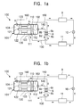
- FIG. 1a is a schematic view showing a refrigerant circuit at the time of cooling operation using a compressor in accordance with an embodiment of a first invention as an internal high pressure type
- FIG. lb is a schematic view showing a refrigerant circuit at the time of heating operation using a compressor in accordance with an embodiment of the first invention as an internal low pressure type
- FIGS. 2a and 2b are schematic views showing a first modification of a compressor of the first invention
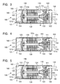
- FIG. 3 is an enlarged sectional view showing a second modification of a compressor of the first invention
- FIG. 4 is an enlarged sectional view showing a third modification of a compressor of the first invention
- FIG. 5 is an enlarged sectional view showing a fourth modification of a compressor of the first invention
- FIG. 1a is a schematic view showing a refrigerant circuit at the time of cooling operation using a compressor in accordance with an embodiment of a first invention as an internal high pressure type
- FIG. lb is a schematic view showing a refrig
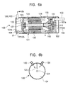
- FIG. 6a is an enlarged sectional view showing a fifth modification of a compressor of the first invention
- FIG. 6b is a sectional view taken along the line VIb-VIb of FIG. 6a
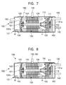
- FIG. 7 is an enlarged sectional view showing a sixth modification of a compressor of the first invention
- FIG. 8 is an enlarged sectional view showing a seventh modification of a compressor of the first invention
- FIG. 9 is an enlarged sectional view showing an eighth modification of a compressor of the first invention
- FIG. 10 is an enlarged sectional view showing a ninth modification of a compressor of the first invention
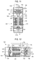
- FIG. 11 is an enlarged sectional view showing a tenth modification of a compressor of the first invention
- FIG. 12 is an enlarged sectional view showing an eleventh modification of a compressor of the first invention
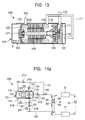
- FIG. 13 is an enlarged sectional view showing a twelfth modification of a compressor of the first invention
- FIG. 14a is a schematic view showing a refrigerant circuit at the time of cooling operation using a compressor in accordance with an embodiment of a second invention as an internal high pressure type
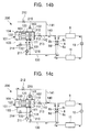
- FIG. 14b is a schematic view showing a refrigerant circuit at the time of start when heating operation is performed using a compressor in accordance with an embodiment of the second invention as an internal low pressure type
- FIG. 14c is a schematic view showing a refrigerant circuit at the time of steady heating operation using a compressor in accordance with an embodiment of the second invention as an internal high pressure type
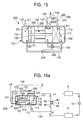
- FIG. 15 is an enlarged sectional view showing another embodiment of a compressor applied to the second invention
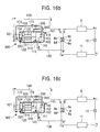
- FIG. 16a is a schematic view showing a refrigerant circuit at the time of cooling operation using a compressor in accordance with an embodiment of a third invention as an internal high pressure type
- FIG. 16b is a schematic view showing a refrigerant circuit at the time of start when heating operation is performed using a compressor in accordance with an embodiment of the third invention as an internal low pressure type
- FIG. 16c is a schematic view showing a refrigerant circuit at the time of steady heating operation using a compressor in accordance with an embodiment of the third invention as an internal high pressure type
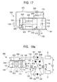
- FIG. 17 is an enlarged sectional view of a compressor applied to the third invention
- FIG. 16a is a schematic view showing a refrigerant circuit at the time of cooling operation using a compressor in accordance with an embodiment of a third invention as an internal high pressure type
- FIG. 16b is a schematic view showing a refrigerant circuit at the time of start
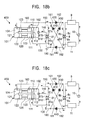
- FIG. 18a is a schematic view showing a refrigerant circuit at the time of cooling operation using a compressor in accordance with an embodiment of a fourth invention as an internal high pressure type
- FIG. 18b is a schematic view showing a refrigerant circuit at the time of start when heating operation is performed using a compressor in accordance with an embodiment of the fourth invention as an internal low pressure type
- FIG. 18c is a schematic view showing a refrigerant circuit at the time of steady heating operation using a compressor in accordance with an embodiment of the fourth invention as an internal high pressure type
- FIG. 19a is a schematic view showing a refrigerant circuit at the time of cooling operation using a compressor in accordance with a modification of the fourth invention as an internal high pressure type
- FIG. 19b is a schematic view showing a refrigerant circuit at the time of start when heating operation is performed using a compressor in accordance with a modification of the fourth invention as an internal low pressure type
- FIG. 19c is a schematic view showing a refrigerant circuit at the time of steady heating operation using a compressor in accordance with a modification of the fourth invention as an internal high pressure type
- FIG. 20 is a schematic view showing a refrigerant circuit of a first prior art using an internal high pressure type compressor
- FIG. 21 is a schematic view showing a refrigerant circuit of a second prior art using an internal low pressure type compressor.
- a heat exchanging circuit comprising a four-way switching valve, an outdoor-side heat exchanger, an expansion valve (or a capillary tube), and an indoor-side heat exchanger is essentially the same as that of the prior art described with reference to FIGS. 20 and 21, so that the same reference numerals are applied.
- An air conditioner in accordance with the first invention has a refrigerant circuit comprising a compressor 100, a four-way switching valve 8, an outdoor-side heat exchanger 9 and an indoor-side heat exchanger 11 which are selectively switched and connected to the high-pressure refrigerant discharge side and the low-pressure refrigerant suction side of the compressor 100 via the four-way switching valve 8, and an expansion valve 10 between the outdoor-side heat exchanger 9 and the indoor-side heat exchanger 11.
- the expansion valve 10 may be a capillary tube.
- the compressor 100 has a cylindrical enclosed vessel 101, and the enclosed vessel 101 contains a refrigerant compressing section 110 having a suction port 111 and a discharge port 112, and an electric motor 120 for driving the refrigerant compressing section 110.
- the enclosed vessel 101 is horizontally disposed on a base frame, not shown, with the axis thereof being substantially horizontal.
- the refrigerant compressing section 110 being of a scroll type, has a compression chamber formed by engaging a fixed scroll having a spiral wrap on an end plate with an orbiting scroll driven by the electric motor 120.
- the interior of the enclosed vessel 101 is airtightly divided into two chambers, a refrigerant discharge chamber 102 on the side of the discharge port 112 and an electric motor chamber 103 containing the electric motor 120, by the end plate on the side of the fixed scroll in the refrigerant compressing section 110.
- the electric motor chamber 103 is provided with a bearer plate 122 which pivotally supports a driving shaft 121 of the electric motor 120.
- a subsidiary electric motor chamber 104 is formed on the side opposite to the refrigerant discharge chamber 102 of the electric motor chamber 103 by the bearer plate 122.
- the bearer plate 122 is formed with an arbitrary number of refrigerant flowing holes 123.
- the suction port 111 of the refrigerant compressing section 110 is connected with a refrigerant suction pipe 130 for sucking a low-pressure refrigerant from a first switching port 8a, which is on the low-pressure refrigerant introduction side of the four-way switching valve 8.
- the refrigerant discharge chamber 102 is connected with a refrigerant discharge pipe 140 for supplying a high-pressure refrigerant produced in the refrigerant compressing section 110 to a second switching port 8b, which is on the high-pressure refrigerant discharge side of the four-way switching valve 8.
- the electric motor chamber 103 is connected to one end of a first refrigerant flow path pipe 150, and the other end of the first refrigerant flow path pipe 150 is connected to a third switching port 8c of the four-way switching valve 8.
- the subsidiary electric motor chamber 104 is connected with one end of a second refrigerant flow path pipe 160, and the other end of the second refrigerant flow path pipe 160 is connected to the outdoor-side heat exchanger 9.
- a remaining one switching port 8d of the four-way switching valve 8 is connected with the indoor-side heat exchanger 11.
- the four-way switching valve 8 is switched as shown in FIG. la so that the first switching port 8a and the fourth switching port 8d are in a communicating state, and the second switching port 8b and the third switching port 8c are in a communicating state.
- a high-temperature high-pressure refrigerant gas produced in the refrigerant compressing section 110 flows into the electric motor chamber 103 from the refrigerant discharge chamber 102 through the refrigerant discharge pipe 140, the second switching port 8b, the third switching port 8c, and the first refrigerant flow path pipe 150, increasing the pressure in the compressor 100, and is supplied to the outdoor-side heat exchanger 9 through the second refrigerant flow path pipe 160.
- the high-temperature high-pressure refrigerant gas is heat exchanged with the outdoor air in the outdoor-side heat exchanger 9, and is condensed and liquefied by discharging heat to the outside of the room.
- This liquid refrigerant is decompressed by the expansion valve 10, becoming in a low-temperature low-pressure gas-liquid two-phase state, and is sent to the indoor-side heat exchanger 11.
- the refrigerant While flowing in the indoor-side heat exchanger 11, the refrigerant is evaporated by taking heat away from the indoor air, becoming a low-temperature low-pressure refrigerant gas, and is returned to the refrigerant compressing section 110 through the fourth switching port 8d and the first switching port 8a of the four-way switching valve 8, the refrigerant suction pipe 130, and the suction port 111.
- the four-way switching valve 8 is switched as shown in FIG. lb so that the second switching port 8b and the fourth switching port 8d are in a communicating state, and the first switching port 8a and the third switching port 8c are in a communicating state.
- the high-temperature high-pressure refrigerant gas produced in the refrigerant compressing section 110 is supplied from the refrigerant discharge chamber 102 to the side of the indoor-side heat exchanger 11 through the refrigerant discharge pipe 140, the second switching port 8b, and the fourth switching port 8d, by which heating of the room is performed.
- the low-pressure refrigerant gas passing through the expansion valve 10 and the outdoor-side heat exchanger 9 flows into the electric motor chamber 103 from the side of the subsidiary electric motor chamber 104 through the second refrigerant flow path pipe 160, decreasing the pressure in the compressor 100, and is returned to the refrigerant compressing section 110 through the first refrigerant flow path pipe 150, the third switching port 8c, the first switching port 8a, the refrigerant suction pipe 130, and the suction port 111.
- the compressor 100 can be made the internal high pressure type at the time of cooling operation, and the compressor 100 can be made the internal low pressure type at the time of heating operation.
- the refrigerant which has been accumulated in the compression chamber at the time of stoppage, is compressed simultaneously with the start, and the high-temperature high-pressure refrigerant gas is directly supplied to the indoor-side heat exchanger, not being caused to pass through the electric motor chamber, unlike the internal high pressure type. Therefore, a sufficient refrigerant circulating amount is secured from the start, so that the temperature can be increased properly.
- FIGS. 2a and 2b show a first modification
- the four-way switching valve 8 may be installed integrally with the compressor 100.
- FIG. 2a shows a state in which the four-way switching valve 8 is switched to the internal high pressure type
- FIG. 2b shows a state in which the four-way switching valve 8 is switched to the internal low pressure type.
- the low-pressure refrigerant suction pipe 130 and the first refrigerant flow path pipe 150 are not laid on the outside of the enclosed vessel 101 as in the case of the above-described embodiment, but should preferably be attached to an end face 101a on the side of the refrigerant discharge chamber 102 of the enclosed vessel 101.
- the low-pressure refrigerant suction pipe 130 is caused to pass through the refrigerant discharge chamber 102 and is connected to the suction port 111 of the refrigerant compressing section 110
- the first refrigerant flow path pipe 150 is caused to pass through the refrigerant discharge chamber 102 and the refrigerant compressing section 110 and is drawn into the electric motor chamber 103, by which the installation space for the low-pressure refrigerant suction pipe 130 and the first refrigerant flow path pipe 150 need not be provided on the peripheral surface (shell periphery) side of the enclosed vessel 101.
- the second refrigerant flow path pipe 160 should also preferably be connected to an end face 101b on the side of the subsidiary electric motor chamber 104 of the enclosed vessel 101.
- the first and second refrigerant flow path pipes 150 and 160 are laid so as to be opposed to coils 124, 124 exposed at both ends of the electric motor 120 so that the refrigerant gas is blown to the coils 124, 124.
- a lubricating oil is separated from the gas efficiently, so that especially at the time of heating operation, the oil surface level H in the electric motor chamber 103 and the subsidiary electric motor chamber 104 can be secured.
- the low-pressure refrigerant suction pipe 130 may be drawn into the refrigerant discharge chamber 102 from the end face 101a on the side of the refrigerant discharge chamber 102 of the enclosed vessel 101, and may be connected to the suction port 111 of the refrigerant compressing section 110.
- the second refrigerant flow path pipe 160 may be laid at a corner portion above the subsidiary electric motor chamber 104 or on the end face 101b on the side of the subsidiary electric motor chamber 104.
- the low-pressure refrigerant suction pipe 130, the first refrigerant flow path pipe 150, and the high-pressure refrigerant discharge pipe 140 are installed on the side of one end face 101a of the enclosed vessel 101, and the second refrigerant flow path pipe 160 is installed on the side of the other end face 101b of the enclosed vessel 101.
- the low-pressure refrigerant suction pipe 130 passes through the refrigerant discharge chamber 102 and is connected to the suction port 111 of the refrigerant compressing section 110, and the first refrigerant flow path pipe 150 passes through the refrigerant discharge chamber 102 and the refrigerant compressing section 110 and is drawn into the electric motor chamber 103.
- the first refrigerant flow path pipe 150 is laid on the coil 124 close to the subsidiary electric motor chamber 104 of the electric motor 120, and the second refrigerant flow path pipe 160 is installed at the upper part of the subsidiary electric motor chamber 104 or on the end face 101b on the side of the subsidiary electric motor chamber 104 as indicated by the chain line in the figure.
- the heating of the refrigerant gas due to the electric motor 120 is less, so that the compression performance at the time of heating operation is increased.
- the pressure difference between the electric motor chamber 103 on the side of the refrigerant compressing section 110 and the subsidiary electric motor chamber 104 decreases, so that the decrease in the oil surface level H in the subsidiary electric motor chamber 104 can be minimized.
- both of the first refrigerant flow path pipe 150 and the second refrigerant flow path pipe 160 are installed at the upper part of the subsidiary electric motor chamber 104.
- both of the refrigerant flow path pipes 150 and 160 are preferably installed symmetrically with respect to the axis of the enclosed vessel 101, that is, with respect to an imaginary vertical plane comprising the axis of the driving shaft 121, and at an angle such as to point at the axis, and also a oil separating plate 125 is provided therebetween.
- the lubricating oil can be separated from the refrigerant gas efficiently.
- the heating of the refrigerant gas due to the electric motor 120 is less, so that the compression performance at the time of heating operation is increased.
- the first refrigerant flow path pipe 150 is provided at a position opposing to the upper center of the electric motor 120, and the second refrigerant flow path pipe 160 is provided on the side of the subsidiary electric motor chamber 104.
- the oil surface levels H on both sides of the electric motor 120 can be kept approximately equal.
- the heating of the refrigerant gas due to the electric motor 120 is less, so that the compression performance at the time of heating operation is increased.
- the second refrigerant flow path pipe 160 may be provided at a position opposing to the coil 124 on the side of the subsidiary electric motor chamber 104 of the electric motor 120.
- both of the first refrigerant flow path pipe 150 and the second refrigerant flow path pipe 160 are arranged at positions opposing to the upper center of the electric motor 120 so as to be shifted at a predetermined interval along the peripheral direction of the enclosed vessel 101, and the refrigerant gas is blown to the electric motor 120 from either one of the refrigerant flow path pipes.
- the lubricating oil can be separated from the refrigerant gas efficiently.
- the oil surface levels H on both sides of the electric motor 120 can be kept approximately equal.
- both of the first refrigerant flow path pipe 150 and the second refrigerant flow path pipe 160 may be arranged at positions between the electric motor 120 and the refrigerant compressing section 110 so as to be shifted at a predetermined interval along the peripheral direction of the enclosed vessel 101.
- the oil surface levels H on both sides of the electric motor 120 can be kept approximately equal.
- the heating of the refrigerant gas due to the electric motor 120 is less, so that the compression performance at the time of heating operation is increased.
- the low-pressure refrigerant suction pipe 130 and the high-pressure refrigerant discharge pipe 140 are installed on the end face 101a on the side of the refrigerant discharge chamber 102 of the enclosed vessel 101.
- both of the first refrigerant flow path pipe 150 and the second refrigerant flow path pipe 160 may also be arranged on the end face 101b on the side of the subsidiary electric motor chamber 104.
- a pipe need not be laid at the shell periphery 101c of the enclosed vessel 101. Therefore, when a heat insulating material is installed around the compressor 100, the work is made easy.
- the enclosed vessel 101 can be assembled accurately without distortion, but also the oil surface levels H on both sides of the electric motor 120 can be kept approximately equal. Also, the heating of the refrigerant gas due to the electric motor 120 is less, so that the compression performance at the time of heating operation can be increased.
- FIG. 11 shows a tenth modification.
- This figure shows a case where the compressor 100 is used as a so-called vertical type.
- the refrigerant compressing section 110 and the electric motor 120 serving as driving means therefor are contained in the enclosed vessel 101 in such a manner that the former is positioned above and the latter is below. Therefore, in the enclosed vessel 101, the refrigerant discharge chamber 102, the electric motor chamber 103, and the subsidiary electric motor chamber 104 are arranged in that order from the upside.
- the high-pressure refrigerant discharge pipe 140 connected to the refrigerant discharge chamber 102 and the first refrigerant flow path pipe 150 connected to the electric motor chamber 103 be arranged at the side on, for example, the right of the enclosed vessel 101 in FIG. 11, and the low-pressure refrigerant suction pipe 130 connected to the suction port 111 and the second refrigerant flow path pipe 160 connected to the electric motor chamber 103 be arranged at the side on, for example, the left of the enclosed vessel 101.
- a pipe need not be laid on the side of the end faces 101a and 101b of the enclosed vessel 101. Accordingly, of the installation space of the compressor 100, the space in the height direction can be decreased.
- first and second refrigerant flow path pipes 150 and 160 are arranged at a part of the upper coil 124 of the electric motor 120, the separation efficiency of the refrigerant gas and lubricating oil can be increased. Also, the heating of the refrigerant gas due to the electric motor 120 is less, so that the compression performance at the time of heating operation can be increased.
- FIG. 12 shows an eleventh modification. This figure shows a case where the compressor 100 is of a so-called horizontal type, and is exclusively used as an internal low pressure type.
- the low-pressure refrigerant suction pipe 130 is disposed so as to be opposed to the coil 124 on the side of the refrigerant compressing section 110 of the electric motor 120 in the electric motor chamber 103, and a bypass pipe 170 is drawn from a portion corresponding to the coil 124 on the side of the subsidiary electric motor chamber 104 of the electric motor 120, and is connected to the suction port 111 of the refrigerant compressing section 110.
- the low-pressure refrigerant suction pipe 130 is connected to the first switching port 8a of the four-way switching valve 8, and the high-pressure refrigerant discharge pipe 140 of the refrigerant discharge chamber 102 is connected to the second switching port 8b of the four-way switching valve 8.
- the third switching port 8c of the four-way switching valve 8 is connected with, for example, the outdoor-side heat exchanger 9, and the remaining fourth switching port 8d is connected with, for example, the indoor-side heat exchanger 11.
- the low-pressure refrigerant gas from the low-pressure refrigerant suction pipe 130 always passes through the electric motor chamber 103 and is returned to the refrigerant compressing section 110.
- the oil surface level H in the subsidiary electric motor chamber 104 can be kept high.
- FIG. 13 shows a twelfth modification.
- This figure shows the case where the compressor 100 is of a so-called horizontal type, and is exclusively used as an internal high pressure type.
- This modification is based on the second modification shown in FIG. 3.
- the low-pressure refrigerant suction pipe 130 is directly connected to the suction port 111 of the refrigerant compressing section 110.
- the second refrigerant flow path pipe 160 is drawn from a portion corresponding to the coil 124 on the side of the subsidiary electric motor chamber 104 of the electric motor 102.
- a bypass pipe 171 is drawn from a portion corresponding to the coil 124 on the side of the refrigerant compressing section 110 of the electric motor 102, and the bypass pipe 171 is connected to the refrigerant discharge chamber 102.
- the low-pressure refrigerant suction pipe 130 is connected to the first switching port 8a of the four-way switching valve 8, and the second refrigerant flow path pipe 160 is connected to the second switching port 8b of the four-way switching valve 8.
- the third switching port 8c of the four-way switching valve 8 is connected with, for example, the outdoor-side heat exchanger 9, and the remaining fourth switching port 8d is connected with, for example, the indoor-side heat exchanger 11.
- the high-temperature high-pressure refrigerant gas from the refrigerant discharge chamber 102 always passes through the electric motor chamber 103 and is discharged through the second refrigerant flow path pipe 160.
- the oil surface level H in the subsidiary electric motor chamber 104 can be kept high.
- cooling operation by means of the internal high pressure type (FIG. 14a)
- heating operation by means of the internal low pressure type (FIG. 14b)
- further heating operation by means of the internal high pressure type (FIG. 14c) can be performed by using one compressor.
- the compressor which is denoted by reference numeral 200, has the same basic configuration as that of the compressor 100 used for the first invention. Therefore, reference numerals for the compressor 100 are applied to the configuring elements of the compressor 200 which are the same or regarded as the same. For the details, the above-described first invention should be referred to.
- this compressor 200 also has a horizontal-type cylindrical enclosed vessel 101, and the enclosed vessel 101 contains the refrigerant compressing section 110 having the suction port 111 and the discharge port 112, and the electric motor 120 for driving the refrigerant compressing section 110.
- the interior of the enclosed vessel 101 is divided airtightly into two chambers, the refrigerant discharge chamber 102 on the side of the discharge port of the refrigerant compressing section and the electric motor chamber 103 containing the electric motor 120, by the refrigerant compressing section 110 serving as partitioning means.
- the subsidiary electric motor chamber 104 is formed by the bearer plate 122 which pivotally supports the driving shaft 121 of the electric motor 120.
- the bearer plate 122 is formed with an arbitrary number of refrigerant flowing holes, so that the electric motor chamber 103 and the subsidiary electric motor chamber 104 communicate with each other.
- the low-pressure refrigerant suction pipe 130 which is drawn from the first switching port 8a on the low-pressure refrigerant discharge side of the four-way switching valve 8 branches into two pipes at an intermediate position.
- a first branch suction pipe 131 one of the branch pipes, is connected directly to the suction port 111 of the refrigerant compressing section 110.
- This first branch suction pipe 131 is provided with a first opening/closing valve 210.
- a second branch suction pipe 132, the other of the branch pipes, is connected to the electric motor chamber 103, and this second branch suction pipe 132 is provided with a second opening/closing valve 211.
- the high-pressure refrigerant discharge pipe 140 connected to the second switching port 8b on the high-pressure refrigerant introduction side of the four-way switching valve 8 also branches into two pipes at an intermediate position.
- a first branch discharge pipe 141, one of the branch pipes, is connected to the subsidiary electric motor chamber 104.
- This first branch discharge pipe 141 is provided with a third opening/closing valve 212.
- a second branch discharge pipe 142, the other of the branch pipes, is connected to the refrigerant discharge chamber 102.
- This second branch discharge pipe 142 is provided with a fourth opening/closing valve 213.
- a first bypass pipe 133 reaching the subsidiary electric motor chamber 104 branches off from the downstream side of the first opening/closing valve 210 of the first branch suction pipe 131.
- This first bypass pipe 133 is provided with a fifth opening/closing valve 214.
- a second bypass pipe 143 is provided between the electric motor chamber 103 and the refrigerant discharge chamber 102.
- This second bypass pipe 143 is provided with a sixth opening/closing valve 215.
- the second bypass pipe 143 may be laid between the upstream side of the fourth opening/closing valve of the second branch discharge pipe 142 and the electric motor chamber 103.
- the third switching port 8c of the four-way switching valve 8 is connected with the outdoor-side heat exchanger 9, and the fourth switching port 8d of the four-way switching valve 8 is connected with the indoor-side heat exchanger 11.
- the second switching port 8b and the third switching port 8c are made in a communicating state
- the first switching port 8a and the fourth switching port 8d are made in a communicating state by the four-way switching valve 8.
- the first opening/closing valve 210, the third opening/closing valve 212, and the sixth opening/closing valve 215 are opened, and the second opening/closing valve 211, the fourth opening/closing valve 213, and the fifth opening/closing valve 214 are closed.
- the low-pressure refrigerant gas is sucked into the refrigerant compressing section 110 through the low-pressure refrigerant suction pipe 130 and the first branch suction pipe 131, and the high-temperature high-pressure refrigerant gas produced in the refrigerant compressing section 110 is supplied to the side of the outdoor-side heat exchanger 9 through the refrigerant discharge chamber 102, the second bypass pipe 143, the electric motor chamber 103, the subsidiary electric motor chamber 104, the first branch discharge pipe 141, the high-pressure refrigerant discharge pipe 140, and the four-way switching valve 8.
- the compressor 200 is used as the internal high pressure type, so that a high-performance steady operation is performed as compared with the internal low pressure type.
- the second switching port 8b and the fourth switching port 8d are made in a communicating state
- the first switching port 8a and the third switching port 8c are made in a communicating state by the four-way switching valve 8.
- the second opening/closing valve 211, the fourth opening/closing valve 213, and the fifth opening/closing valve 214 are opened, and the first opening/closing valve 210, the third opening/closing valve 212, and the sixth opening/closing valve 215 are closed.
- the low-pressure refrigerant gas enters the electric motor chamber 103 through the low pressure refrigerant suction pipe 130 and the second branch suction pipe 132, and is sucked into the suction port 111 of the refrigerant compressing section 110 from the subsidiary electric motor chamber 104 through the first bypass pipe 133.
- the high-temperature high-pressure refrigerant gas produced in the refrigerant compressing section 110 is supplied to the side of the indoor-side heat exchanger 11 through the refrigerant discharge chamber 102, the second branch discharge pipe 142, the high-pressure refrigerant discharge pipe 140, and the four-way switching valve 8.
- the compressor 200 is used as the internal low pressure type, so that warm air can be blown out from the indoor-side heat exchanger 11 in a short period of time from the start by preventing the high-temperature high-pressure refrigerant gas from passing through the electric motor chamber 103.
- the required time from the start to the warm air blowout is about 3 minutes.
- the required time can be shortened to about 1 minute.
- the first opening/closing valve 210, the third opening/closing valve 212, and the sixth opening/closing valve 215 are opened, and contrarily the second opening/closing vale 211, the fourth opening/closing valve 213, and the fifth opening/closing valve 214 are closed.
- the compressor 200 is switched to the internal high pressure type.
- the flow of refrigerant at this time is shown in FIG. 14c. According to this embodiment, as in the case of cooling operation, a high-performance heating operation can be performed.
- the switching control of the refrigerant circuit can be carried out exactly.
- the second opening/closing valve 211 may be a check valve.
- the third opening/closing valve 212 may be a check valve.
- the compressor 200 has pipes and switching valves as described below.
- the low-pressure refrigerant suction pipe 130 drawn from the first switching port 8a on the low-pressure refrigerant discharge side of the four-way switching valve 8 branches into two pipes at an intermediate position.
- a first branch suction pipe 135, one of the branch pipes, is connected directly to the suction port 111 of the refrigerant compressing section 110.
- This first branch suction pipe 135 is provided with a first opening/closing valve 220.
- a second branch suction pipe 136 is connected to the electric motor chamber 103.
- a first check valve 230 for checking a reverse flow from the side of the electric motor chamber 103.
- a first bypass pipe 137 is provided between the downstream side of the first opening/closing valve 220 of the first branch suction pipe 135 and the electric motor chamber 103.
- This first bypass pipe 137 is provided with a second opening/closing valve 221.
- the second switching port 8b (for example, see FIG. 14a) on the high-pressure refrigerant introduction side of the four-way switching valve 8 and the subsidiary electric motor chamber 104 are connected to each other by the high-pressure refrigerant discharge pipe 140.
- the refrigerant discharge chamber 102 and the electric motor chamber 103 are connected to each other via a second bypass pipe 145.
- This second bypass pipe 145 is provided with a third opening/closing valve 222.
- a third bypass pipe 146 having a fourth opening/closing valve 223 is provided between the upstream side of the third opening/closing valve 222 of the second bypass pipe 145 and the subsidiary electric motor chamber 104.
- a partition 126 having a communicating hole 127 is provided between the electric motor chamber 103 and the subsidiary electric motor chamber 104 separately from the bearer plate 122.
- the communicating hole 127 in this partition 126 is provided with a second check valve 231 for checking a reverse flow from the side of the subsidiary electric motor chamber 104 to the side of the electric motor chamber 103.
- the second check valve 231 may be provided at the communicating hole in the bearer plate 122. In this case, the partition 126 need not be provided especially.
- the third switching port 8c of the four-way switching valve 8 is connected with the outdoor-side heat exchanger 9, and the fourth switching port 8d of the four-way switching valve 8 is connected with the indoor-side heat exchanger 11.
- the high-pressure refrigerant discharge pipe 140 of the second switching port 8b and the outdoor-side heat exchanger 9 of the third switching port 8c are caused to communicate with each other and the low-pressure refrigerant suction pipe 130 of the first switching port 8a and the indoor-side heat exchanger 11 of the fourth switching port 8d are caused to communicate with each other by the four-way switching valve 8.
- the first opening/closing valve 220 and the third opening/closing valve 222 are opened, and the second opening/closing valve 221 and the fourth opening/closing valve 223 are closed. Thereby, the compressor 200 is operated as the internal high pressure type.
- the low-pressure refrigerant from the indoor-side heat exchanger 11 is sucked into the refrigerant compressing section 110 from the suction port 111 through the low-pressure refrigerant suction pipe 130 and the first branch suction pipe 135.
- the high-temperature high-pressure refrigerant gas produced in the refrigerant compressing section 110 is supplied to the electric motor chamber 103 through the second bypass pipe 145. Thereby, the first check valve 230 is closed. Thereafter, the high-temperature high-pressure refrigerant gas pushes to open the second check valve 231 and flows into the subsidiary electric motor chamber 104, and then is supplied to the outdoor-side heat exchanger 9 through the high-pressure refrigerant discharge pipe 140 and the four-way switching valve 8.
- the high-pressure refrigerant discharge pipe 140 of the second switching port 8b and the indoor-side heat exchanger 11 of the fourth switching port 8d are caused to communicate with each other and the low-pressure refrigerant suction pipe 130 of the first switching port 8a and the outdoor-side heat exchanger 9 of the third switching port 8c are caused to communicate with each other by the four-way switching valve 8.
- the second opening/closing valve 221 and the fourth opening/closing valve 223 are opened, and the first opening/closing valve 220 and the third opening/closing valve 222 are closed.
- the compressor 200 is operated as the internal low pressure type.
- the low-pressure refrigerant from the outdoor-side heat exchanger 9 flows into the electric motor chamber 103 through the low-pressure refrigerant suction pipe 130 and the second branch suction pipe 136, decreasing the pressure in the compressor, and then is sucked into the refrigerant compressing section 110 from the suction port 111 through the first bypass pipe 137.
- the high-temperature high-pressure refrigerant gas produced in the refrigerant compressing section 110 is supplied from the refrigerant discharge chamber 102 to the subsidiary electric motor chamber 104 through the second bypass pipe 146.
- the second check valve 231 is closed.
- the high-temperature high-pressure refrigerant gas is supplied to the indoor-side heat exchanger 11 through the high-pressure refrigerant discharge pipe 140 and the four-way switching valve 8.
- the four-way switching valve 8 being as it is, the first opening/closing valve 220 and the third opening/closing valve 222 are opened, and the second opening/closing valve 221 and the fourth opening/closing valve 223 are closed. Thereby, the compressor 200 is operated as the internal high pressure type.
- first opening/closing valve 220 and the second opening/closing valve 221 should preferably be interlocking valves, in which when either one of the valves is opened, the other valve is closed, from the viewpoint of the valve switching control.
- the third opening/closing valve 222 and the fourth opening/closing valve 223 should preferably be interlocking valves, in which when either one of the valves is opened, the other valve is closed.
- cooling operation by means of the internal high pressure type (FIG. 16a)
- heating operation by means of the internal low pressure type (FIG. 16b)
- further heating operation by means of the internal high pressure type (FIG. 16c) can be performed by using one compressor.
- the compressor which is denoted by reference numeral 300, has the same basic configuration as that of the compressor 100 used for the first invention. Therefore, reference numerals for the compressor 100 are applied to the elements of the compressor 300 which are the same or regarded as the same. For the details, the above-described first invention should be referred to.
- this compressor 300 also has a horizontal-type cylindrical enclosed vessel 101, and the enclosed vessel 101 contains the refrigerant compressing section 110 having the suction port 111 and the discharge port 112, and the electric motor 120 for driving the refrigerant compressing section 110.
- the interior of the enclosed vessel 101 is divided airtightly into two chambers, the refrigerant discharge chamber 102 on the side of the discharge port of the refrigerant compressing section and the electric motor chamber 103 containing the electric motor 120, by the refrigerant compressing section 110 serving as partitioning means.
- the subsidiary electric motor chamber 104 is formed by the bearer plate 122 which pivotally supports the driving shaft 121 of the electric motor 120.
- the bearer plate 122 is formed with an arbitrary number of refrigerant flowing holes, so that the electric motor chamber 103 and the subsidiary electric motor chamber 104 communicate with each other. Therefore, these two chambers may be regarded substantially as one chamber.
- the refrigerant compressing section 110 has a refrigerant inflow port 113 reaching the suction port 111 from the side of the electric motor chamber 103, separately from the suction port 111.
- the suction port 111 is connected with the low-pressure refrigerant suction pipe 130 drawn from the first switching port 8a on the low-pressure refrigerant discharge side of the four-way switching valve 8.
- the refrigerant inflow port 113 is provided with a first opening/closing valve 310.
- the first opening/closing valve 310 is urged by spring means 311 in the direction such that the inflow port is always opened.
- the spring urging force is regulated so that when the pressure in the electric motor chamber 103 reaches a predetermined value, the refrigerant inflow port 113 is closed.
- the subsidiary electric motor chamber 104 and the second switching port 8b on the high-pressure refrigerant introduction side of the four-way switching valve 8 are connected to each other by the high-pressure refrigerant discharge pipe 140.
- This high-pressure refrigerant discharge pipe 140 is provided with a second opening/closing valve 320.
- the second opening/closing valve 320 comprising a check valve for checking a reverse flow from the side of high-pressure refrigerant discharge pipe 140 to the side of the subsidiary electric motor chamber 104, is disposed at a connecting portion of the subsidiary electric motor chamber 104 and the high-pressure refrigerant discharge pipe 140.
- the downstream side of the second opening/closing valve 320 of the high-pressure refrigerant discharge pipe 140 and the refrigerant discharge chamber 102 are connected to each other by a first bypass pipe 172.
- This first bypass pipe 172 is provided with a third opening/closing valve 330.
- a second bypass pipe 173 having a fourth opening/closing valve 340 is provided between the upstream side of the third opening/closing valve 330 of the first bypass pipe 172 and the electric motor chamber 103.
- the interlocking valves in which when either one of the valves is opened, the other valve is closed, are used for the third opening/closing valve 330 and the fourth opening/closing valve 340.
- the third switching port 8c of the four-way switching valve 8 is connected with the outdoor-side heat exchanger 9
- the fourth switching port 8d of the four-way switching valve 8 is connected with the indoor-side heat exchanger 11.
- the high-pressure refrigerant discharge pipe 140 of the second switching port 8b and the outdoor-side heat exchanger 9 of the third switching port 8c are caused to communicate with each other and the low-pressure refrigerant suction pipe 130 of the first switching port 8a and the indoor-side heat exchanger 11 of the fourth switching port 8d are caused to communicate with each other by the four-way switching valve 8.
- the fourth opening/closing valve 340 is opened, and the third opening/closing valve 330 is closed. Thereby, the compressor 300 is operated as the internal high pressure type.
- the low-pressure refrigerant gas from the side of the indoor-side heat exchanger 11 is sucked into the refrigerant compressing section 110 from the suction port 111 through the low-pressure refrigerant suction pipe 130, and the high-temperature high-pressure refrigerant gas produced in the refrigerant compressing section 110 is supplied from the refrigerant discharge chamber 102 to the electric motor chamber 103 through the second bypass pipe 173.
- the pressure in the electric motor chamber 103 is made high, and the refrigerant inflow port 113 is closed by the first opening/closing valve 310.
- the high-temperature high-pressure refrigerant gas is supplied to the side of the outdoor-side heat exchanger 9 through the subsidiary electric motor chamber 104, the second opening/closing valve 320, the high-pressure refrigerant discharge pipe 140, and the four-way switching valve 8.
- the high-pressure refrigerant discharge pipe 140 of the second switching port 8b and the indoor-side heat exchanger 11 of the fourth switching port 8d are caused to communicate with each other and the low-pressure refrigerant suction pipe 130 of the first switching port 8a and the outdoor-side heat exchanger 9 of the third switching port 8c are caused to communicate with each other by the four-way switching valve 8.
- the third opening/closing valve 330 is opened, and the second opening/closing valve 320 is closed. Thereby, the compressor 300 is operated as the internal low pressure type.
- the low-pressure refrigerant gas from the side of the outdoor-side heat exchanger 9 is sucked into the refrigerant compressing section 110 from the suction port 111 through the low-pressure refrigerant suction pipe 130.
- the high-temperature high-pressure refrigerant gas produced in the refrigerant compressing section 110 reaches the high-pressure refrigerant discharge pipe 140 from the first bypass pipe 172 without flowing in the electric motor chamber 103 from the refrigerant discharge chamber 102, and is supplied to the indoor-side heat exchanger 11 through the four-way switching valve 8.
- the first opening/closing valve 310 is opened, and therefore the pressure in the electric motor chamber 103 is kept low.
- the four-way switching valve 8 being as it is, the fourth opening/closing valve 340 is opened, and the third opening/closing valve 330 is closed. Thereby, heating operation is continued with the compressor 300 being operated as the internal high pressure type.
- cooling operation by means of the internal high pressure type (FIG. 18a), heating operation by means of the internal low pressure type (FIG. 18b), and further heating operation by means of the internal high pressure type (FIG. 18c) can be performed by using one compressor.
- the compressor which is denoted by reference numeral 400, has the same basic configuration as that of the compressor 100 used for the first invention. Therefore, reference numerals for the compressor 100 are applied to the elements of the compressor 400 which are the same or regarded as the same, and the explanation of these elements is omitted.
- a second four-way switching valve 81 is provided separately from the first four-way switching valve 8.
- the suction port 111 of the refrigerant compressing section 110 is connected with the low-pressure refrigerant suction pipe 130 drawn from a first switching port 81a on the low-pressure refrigerant discharge side of the second four-way switching valve 81. Also, the refrigerant discharge chamber 102 is connected with the high-pressure refrigerant discharge pipe 140 reaching a second switching port 81b on the high-pressure refrigerant introduction side of the second four-way switching valve 81.
- the electric motor chamber 103 is connected with one end of the first refrigerant flow path pipe 150, and the other end of the first refrigerant flow path pipe 150 is connected to a third switching port 81c of the second four-way switching valve 81.
- the subsidiary electric motor chamber 104 is connected with one end of the second refrigerant flow path pipe 160.
- the other end side of the second refrigerant flow path pipe 160 branches into two pipes.
- One branch pipe 161 is connected to the first switching port 8a of the first four-way switching valve 8 via a first opening/closing valve 410.
- the other branch pipe 162 is connected to the second switching port 8b of the first four-way switching valve 8 via a second opening/closing valve 420.
- a fourth switching port 81d of the second four-way switching valve 81 is connected to the first four-way switching valve 8 via a pipe 180.
- This pipe 180 also branches into two pipes.
- One branch pipe 181 is connected to the second switching port 8b of the first four-way switching valve 8 via a third opening/closing valve 430, and the other branch pipe 182 is connected to the first switching port 8a of the first four-way switching valve 8 via a fourth opening/closing valve 440.
- the third switching port 8c of the first four-way switching valve 8 is connected with the outdoor-side heat exchanger 9, and the fourth switching port 8d thereof is connected with the indoor-side heat exchanger 11.
- the first refrigerant flow path pipe 150 is connected to the electric motor chamber 103
- the second refrigerant flow path pipe 160 is connected to the subsidiary electric motor chamber 104.
- the electric motor chamber 103 and the subsidiary electric motor chamber 104 are caused to communicate with each other by the refrigerant communicating hole 123 in the bearer plate 122, so that these two chambers may be regarded substantially as one chamber. Therefore, both of the first refrigerant flow path pipe 150 and the second refrigerant flow path pipe 160 may be connected to the electric motor chamber 103 or the subsidiary electric motor chamber 104.
- both of the first and second four-way switching valves 8 and 81 are switched so that the first switching port 8a, 81a thereof communicates with the fourth switching port 8d, 81d, and at the same time the second switching port 8b, 81b communicates with the third switching port 8c, 81c. Also, the second opening/closing valve 420 and the fourth opening/closing valve 440 are opened, and the first opening/closing valve 410 and the third opening/closing valve 430 are closed.
- the low-pressure refrigerant gas from the indoor-side heat exchanger 11 is sucked into the refrigerant compressing section 110 through the switching ports 8d and 8a of the first four-way switching valve 8, the fourth opening/closing valve 440, the switching ports 81d and 81a of the second four-way switching valve 81, and the low-pressure refrigerant suction pipe 130.
- the high-temperature high-pressure refrigerant gas produced in the refrigerant compressing section 110 is supplied to the electric motor chamber 103 through the high-pressure refrigerant discharge pipe 140, the switching ports 81b and 81c of the second four-way switching valve 81, and the first refrigerant flow path pipe 150, and is supplied from the subsidiary electric motor chamber 104 to the outdoor-side heat exchanger 9 through the second refrigerant flow path pipe 160, the second opening/closing valve 420, and the switching ports 8b and 8c of the first four-way switching valve 8.
- the compressor 400 is operated as the internal high pressure type.
- both of the first and second four-way switching valves 8 and 81 are switched so that the second switching port 8b, 81b thereof communicates with the fourth switching port 8d, 81d, and at the same time the first switching port 8a, 81a communicates with the third switching port 8c, 81c.
- the first opening/closing valve 410 and the third opening/closing valve 430 are opened, and the second opening/closing valve 420 and the fourth opening/closing valve 440 are closed.
- the low-pressure refrigerant gas from the outdoor-side heat exchanger 9 flows to the side of the subsidiary electric motor chamber 104 through the switching ports 8c and 8a of the first four-way switching valve 8, the first opening/closing valve 410, and the second refrigerant flow path pipe 160, and is sucked into the refrigerant compressing section 110 from the electric motor chamber 103 through the first refrigerant flow path pipe 150, the switching ports 81c and 81a of the second four-way switching valve 81, and the low-pressure refrigerant suction pipe 130.
- the high-temperature high-pressure refrigerant gas produced in the refrigerant compressing section 110 is supplied to the indoor-side heat exchanger 11 through the high-pressure refrigerant discharge pipe 140, the switching ports 81b and 81d of the second four-way switching valve 81, the third opening/closing valve 430, and the switching ports 8b and 8d of the first four-way switching valve 8.
- the compressor 400 is operated as the internal low pressure type.
- the second four-way switching valve 81 is switched to the state of cooling operation. Specifically, the switching ports 81a and 81d are caused to communicate with each other, and the switching ports 81b and 81c are caused to communicate with each other. Thereby, the compressor 400 can be operated as the internal high pressure type.
- Each opening/closing valve may be a solenoid valve, but it should preferably be a check valve because the check valve does not require electrical valve control.
- a check valve in which the direction from the side of the first four-way switching valve 8 toward the electric motor chamber 103 is the forward direction is used as the first opening/closing valve 410
- a check valve in which the direction from the side of the electric motor chamber 103 toward the first four-way switching valve 8 is the forward direction is used as the second opening/closing valve 420
- a check valve in which the direction from the side of the second four-way switching valve 81 toward the first four-way switching valve 8 is the forward direction is used as the third opening/closing valve 430
- a check valve in which the direction from the side of the first four-way switching valve 8 toward the second four-way switching valve 81 is the forward direction is used as the fourth opening/closing valve 440.
- the fourth invention can be modified as shown in FIGS. 19a to 19c.
- further heating operation by means of the internal high pressure type (FIG. 19c) can be performed by using one compressor 400.
- the second refrigerant flow path pipe 160 and the pipe 180 do not branch, and the opening/closing valves are not used.
- the second refrigerant flow path pipe 160 is connected directly to the second switching port 8b of the first four-way switching valve 8
- the pipe 180 is also connected directly to the first switching port 8a of the first four-way switching valve 8.
- the low-pressure refrigerant suction pipe 130 and the pipe 180 are caused to communicate with each other and the high-pressure refrigerant discharge pipe 140 and the first refrigerant flow path pipe 150 are caused to communicate with each other by the second four-way switching valve 81.
- the second refrigerant flow path pipe 160 and the outdoor-side heat exchanger 9 are caused to communicate with each other and the pipe 180 and the indoor-side heat exchanger 11 are caused to communicate with each other by the first four-way switching valve 8.
- the compressor 400 is operated as the internal high pressure type.
- the second four-way switching valve 81 is switched so that the high-pressure refrigerant discharge pipe 140 and the pipe 180 communicate with each other and the first refrigerant flow path pipe 150 and the low-pressure refrigerant suction pipe 130 communicate with each other.
- the first four-way switching valve 8 remains in the state of cooling operation. Thereby, the compressor 400 is operated as the internal low pressure type.
- the second four-way switching valve 81 is switched so that the low-pressure refrigerant suction pipe 130 and the pipe 180 communicate with each other and the high-pressure refrigerant discharge pipe 140 and the first refrigerant flow path pipe 150 communicate with each other.
- the first four-way switching valve 8 is switched so that the second refrigerant flow path pipe 160 and the indoor-side heat exchanger 11 communicate with each other and the outdoor-side heat exchanger 9 and the pipe 180 communicate with each other.
- the heating operation can be continued with the compressor 400 being operated as the internal high pressure type.
Landscapes
- Engineering & Computer Science (AREA)
- Mechanical Engineering (AREA)
- General Engineering & Computer Science (AREA)
- Physics & Mathematics (AREA)
- Thermal Sciences (AREA)
- Chemical & Material Sciences (AREA)
- Combustion & Propulsion (AREA)
- Compression-Type Refrigeration Machines With Reversible Cycles (AREA)
- Applications Or Details Of Rotary Compressors (AREA)
- Compressor (AREA)
- Air Conditioning Control Device (AREA)
Applications Claiming Priority (10)
| Application Number | Priority Date | Filing Date | Title |
|---|---|---|---|
| JP27944298 | 1998-09-14 | ||
| JP27944198 | 1998-09-14 | ||
| JP27944198A JP4055264B2 (ja) | 1998-09-14 | 1998-09-14 | 空気調和装置 |
| JP10279442A JP2000088387A (ja) | 1998-09-14 | 1998-09-14 | 空気調和装置 |
| JP27888898 | 1998-09-30 | ||
| JP27888998 | 1998-09-30 | ||
| JP10278889A JP2000111187A (ja) | 1998-09-30 | 1998-09-30 | 空気調和装置 |
| JP10278888A JP2000111186A (ja) | 1998-09-30 | 1998-09-30 | 空気調和装置 |
| JP10348082A JP2000171115A (ja) | 1998-12-08 | 1998-12-08 | 空気調和装置 |
| JP34808298 | 1998-12-08 |
Publications (2)
| Publication Number | Publication Date |
|---|---|
| EP0987501A2 true EP0987501A2 (de) | 2000-03-22 |
| EP0987501A3 EP0987501A3 (de) | 2001-08-29 |
Family
ID=27530662
Family Applications (1)
| Application Number | Title | Priority Date | Filing Date |
|---|---|---|---|
| EP99307215A Withdrawn EP0987501A3 (de) | 1998-09-14 | 1999-09-13 | Klimaanlage |
Country Status (8)
| Country | Link |
|---|---|
| US (2) | US6202428B1 (de) |
| EP (1) | EP0987501A3 (de) |
| KR (1) | KR20000023148A (de) |
| CN (1) | CN1154818C (de) |
| AU (1) | AU756840B2 (de) |
| CA (1) | CA2282127A1 (de) |
| MY (1) | MY130739A (de) |
| TW (1) | TW477887B (de) |
Cited By (5)
| Publication number | Priority date | Publication date | Assignee | Title |
|---|---|---|---|---|
| EP1172562A3 (de) * | 2000-07-11 | 2003-01-02 | Fujitsu General Limited | Spiralverdichter |
| EP2175139A3 (de) * | 2008-10-07 | 2013-04-17 | ILMVAC GmbH | Pumpenanordnung mit Pumpeneinheit und Antriebseinheit mit einem Elektromotor mit gekapseltem Motorgehäuse |
| CN108006838A (zh) * | 2018-01-31 | 2018-05-08 | 广东美的制冷设备有限公司 | 空调室内机的壳体组件及空调室内机 |
| EP3696415A1 (de) * | 2019-02-12 | 2020-08-19 | Nabtesco Corporation | Luftverdichtungsvorrichtung und staubvermeidungsverfahren für einen motor |
| CN113932472A (zh) * | 2020-07-10 | 2022-01-14 | 天津城建大学 | 一种基于燃气机热泵和有机朗肯循环耦合系统的运行方法 |
Families Citing this family (21)
| Publication number | Priority date | Publication date | Assignee | Title |
|---|---|---|---|---|
| JP2000291557A (ja) * | 1999-04-07 | 2000-10-17 | Sanden Corp | 電動式圧縮機 |
| JP2002070743A (ja) | 2000-08-29 | 2002-03-08 | Sanden Corp | 冷媒圧縮用電動式圧縮機 |
| JP3976512B2 (ja) | 2000-09-29 | 2007-09-19 | サンデン株式会社 | 冷媒圧縮用電動式圧縮機 |
| JP4073622B2 (ja) | 2000-12-18 | 2008-04-09 | サンデン株式会社 | 電動式圧縮機 |
| JP2002199773A (ja) | 2000-12-27 | 2002-07-12 | Sanden Corp | 圧縮機モータ駆動制御方法及び圧縮機駆動用インバータ装置 |
| JP2003035261A (ja) * | 2001-07-19 | 2003-02-07 | Toyota Industries Corp | 圧縮機 |
| USD466523S1 (en) | 2001-08-10 | 2002-12-03 | Sanden Corporation | Motor-driven compressor |
| JP2003148343A (ja) | 2001-11-08 | 2003-05-21 | Sanden Corp | 電動圧縮機 |
| TW200406547A (en) * | 2002-06-05 | 2004-05-01 | Sanyo Electric Co | Internal intermediate pressure multistage compression type rotary compressor, manufacturing method thereof and displacement ratio setting method |
| USD487473S1 (en) | 2002-11-10 | 2004-03-09 | Sanden Corporation | Motor-driven compressor |
| JP2004270614A (ja) * | 2003-03-11 | 2004-09-30 | Sanden Corp | 電動圧縮機 |
| US7219505B2 (en) * | 2004-10-22 | 2007-05-22 | York International Corporation | Control stability system for moist air dehumidification units and method of operation |
| KR100697879B1 (ko) * | 2005-08-17 | 2007-03-23 | 백기영 | 픽셀을 이용한 데이터의 암호화 및 해독방법 |
| JP2008066102A (ja) | 2006-09-07 | 2008-03-21 | Yamaha Corp | 燃料電池用空気供給装置 |
| JP4079184B1 (ja) * | 2006-10-30 | 2008-04-23 | ダイキン工業株式会社 | 冷凍装置の熱源ユニット、及び冷凍装置 |
| US8080909B2 (en) * | 2009-05-19 | 2011-12-20 | Ford Global Technologies, Llc | Cooling system and method for an electric motor |
| DE102016204756B4 (de) * | 2015-12-23 | 2024-01-11 | OET GmbH | Elektrischer Kältemittelantrieb |
| JP7065681B2 (ja) * | 2018-04-26 | 2022-05-12 | 日立ジョンソンコントロールズ空調株式会社 | 空気調和装置 |
| CN109185156B (zh) * | 2018-11-28 | 2023-08-29 | 江西天一航空装备有限公司 | 一种增强电机散热的涡旋无油空压机 |
| CN110398048B (zh) * | 2019-07-23 | 2022-11-22 | 广东美的暖通设备有限公司 | 空调系统、空调控制方法、空调控制装置和存储介质 |
| CN112032044B (zh) * | 2020-08-10 | 2022-10-21 | 广州万宝集团压缩机有限公司 | 一种压缩机机壳组件、压缩机和调温设备 |
Family Cites Families (13)
| Publication number | Priority date | Publication date | Assignee | Title |
|---|---|---|---|---|
| US2979917A (en) * | 1959-12-07 | 1961-04-18 | Gen Electric | Cooling arrangement for hermetically sealed refrigerant compressor |
| US2978881A (en) * | 1960-02-02 | 1961-04-11 | Westinghouse Electric Corp | Air conditioning apparatus |
| US3006164A (en) * | 1960-09-29 | 1961-10-31 | Gen Electric | Reversible refrigeration system |
| US3006163A (en) * | 1960-09-29 | 1961-10-31 | Gen Electric | Compressor motor cooling arrangement for reversible refrigeration system |
| US3358466A (en) * | 1966-04-25 | 1967-12-19 | American Radiator & Standard | Auxiliary compressor in motor casing for controlling pressure therein |
| JPS5970890A (ja) * | 1982-10-18 | 1984-04-21 | Toshiba Corp | 容量制御圧縮機の冷却装置 |
| JPS5952344B2 (ja) * | 1983-01-25 | 1984-12-19 | 株式会社東芝 | 空気調和装置 |
| JPH07247968A (ja) * | 1994-03-09 | 1995-09-26 | Daikin Ind Ltd | スクロール圧縮機 |
| US5769610A (en) * | 1994-04-01 | 1998-06-23 | Paul; Marius A. | High pressure compressor with internal, cooled compression |
| US5674053A (en) * | 1994-04-01 | 1997-10-07 | Paul; Marius A. | High pressure compressor with controlled cooling during the compression phase |
| US5716197A (en) * | 1994-04-01 | 1998-02-10 | Paul; Marius A. | High pressure compressor with internal, inter-stage cooled compression having multiple inlets |
| JPH08144984A (ja) * | 1994-11-18 | 1996-06-04 | Nippon Soken Inc | ヒートポンプ用電動圧縮機 |
| JPH09112474A (ja) * | 1995-10-17 | 1997-05-02 | Daikin Ind Ltd | 冷媒圧縮機 |
-
1999
- 1999-09-13 TW TW088115755A patent/TW477887B/zh not_active IP Right Cessation
- 1999-09-13 CA CA002282127A patent/CA2282127A1/en not_active Abandoned
- 1999-09-13 EP EP99307215A patent/EP0987501A3/de not_active Withdrawn
- 1999-09-13 US US09/394,714 patent/US6202428B1/en not_active Expired - Fee Related
- 1999-09-13 MY MYPI99003958A patent/MY130739A/en unknown
- 1999-09-14 KR KR1019990039369A patent/KR20000023148A/ko not_active Abandoned
- 1999-09-14 AU AU47599/99A patent/AU756840B2/en not_active Ceased
- 1999-09-14 CN CNB991217764A patent/CN1154818C/zh not_active Expired - Fee Related
-
2001
- 2001-01-24 US US09/767,732 patent/US6276149B2/en not_active Expired - Fee Related
Cited By (6)
| Publication number | Priority date | Publication date | Assignee | Title |
|---|---|---|---|---|
| EP1172562A3 (de) * | 2000-07-11 | 2003-01-02 | Fujitsu General Limited | Spiralverdichter |
| EP2175139A3 (de) * | 2008-10-07 | 2013-04-17 | ILMVAC GmbH | Pumpenanordnung mit Pumpeneinheit und Antriebseinheit mit einem Elektromotor mit gekapseltem Motorgehäuse |
| CN108006838A (zh) * | 2018-01-31 | 2018-05-08 | 广东美的制冷设备有限公司 | 空调室内机的壳体组件及空调室内机 |
| CN108006838B (zh) * | 2018-01-31 | 2024-05-28 | 广东美的制冷设备有限公司 | 空调室内机的壳体组件及空调室内机 |
| EP3696415A1 (de) * | 2019-02-12 | 2020-08-19 | Nabtesco Corporation | Luftverdichtungsvorrichtung und staubvermeidungsverfahren für einen motor |
| CN113932472A (zh) * | 2020-07-10 | 2022-01-14 | 天津城建大学 | 一种基于燃气机热泵和有机朗肯循环耦合系统的运行方法 |
Also Published As
| Publication number | Publication date |
|---|---|
| MY130739A (en) | 2007-07-31 |
| CA2282127A1 (en) | 2000-03-14 |
| KR20000023148A (ko) | 2000-04-25 |
| US20010001923A1 (en) | 2001-05-31 |
| AU4759999A (en) | 2000-03-23 |
| US6276149B2 (en) | 2001-08-21 |
| EP0987501A3 (de) | 2001-08-29 |
| CN1154818C (zh) | 2004-06-23 |
| US6202428B1 (en) | 2001-03-20 |
| AU756840B2 (en) | 2003-01-23 |
| CN1254080A (zh) | 2000-05-24 |
| TW477887B (en) | 2002-03-01 |
Similar Documents
| Publication | Publication Date | Title |
|---|---|---|
| US6202428B1 (en) | Air conditioner | |
| US7631510B2 (en) | Multi-stage refrigeration system including sub-cycle control characteristics | |
| US10378539B2 (en) | System including high-side and low-side compressors | |
| US8857200B2 (en) | Compressor having capacity modulation or fluid injection systems | |
| US6189335B1 (en) | Multi-stage compressing refrigeration device and refrigerator using the device | |
| KR20030044867A (ko) | 다단 압축식 로터리 컴프레서의 제조 방법 | |
| JP2017150466A (ja) | 高圧圧縮機及びそれを備えた冷凍サイクル装置 | |
| US20050214137A1 (en) | Multicylinder rotary compressor and compressing system and refrigerating unit provided with same | |
| KR101212642B1 (ko) | 압축기 용량 제어 조작 기구, 및 그것을 구비한 공기 조화 장치 | |
| JPWO2005010370A1 (ja) | 冷凍装置 | |
| JPH0448160A (ja) | 冷凍サイクル装置 | |
| WO2006073048A1 (ja) | 冷凍サイクル装置及びロータリ式密閉型圧縮機 | |
| US4702088A (en) | Compressor for reversible refrigeration cycle | |
| JP2622960B2 (ja) | スクロール圧縮機の液冷媒噴射装置 | |
| JPH03260391A (ja) | 密閉型ロータリー圧縮機 | |
| JPH02133757A (ja) | 二段圧縮冷凍サイクル | |
| KR101122080B1 (ko) | 공기조화기의 제어방법 | |
| JP4055264B2 (ja) | 空気調和装置 | |
| JP5321055B2 (ja) | 冷凍装置 | |
| EP4553351A1 (de) | Strömungswegschaltventil und kältekreislaufvorrichtung | |
| JP2000171115A (ja) | 空気調和装置 | |
| JPH0518613A (ja) | 冷凍サイクル装置 | |
| KR100767683B1 (ko) | 공기조화기 | |
| JP2003028079A (ja) | スクロール型圧縮機及び空気調和装置 | |
| JP3152614B2 (ja) | 空気調和機 |
Legal Events
| Date | Code | Title | Description |
|---|---|---|---|
| PUAI | Public reference made under article 153(3) epc to a published international application that has entered the european phase |
Free format text: ORIGINAL CODE: 0009012 |
|
| AK | Designated contracting states |
Kind code of ref document: A2 Designated state(s): AT BE CH CY DE DK ES FI FR GB GR IE IT LI LU MC NL PT SE Kind code of ref document: A2 Designated state(s): DE ES FR GB IT |
|
| AX | Request for extension of the european patent |
Free format text: AL;LT;LV;MK;RO;SI |
|
| PUAL | Search report despatched |
Free format text: ORIGINAL CODE: 0009013 |
|
| AK | Designated contracting states |
Kind code of ref document: A3 Designated state(s): AT BE CH CY DE DK ES FI FR GB GR IE IT LI LU MC NL PT SE |
|
| AX | Request for extension of the european patent |
Free format text: AL;LT;LV;MK;RO;SI |
|
| RIC1 | Information provided on ipc code assigned before grant |
Free format text: 7F 24F 3/00 A, 7F 25B 13/00 B, 7F 25B 31/00 B, 7F 04C 23/00 B, 7F 04C 25/00 B |
|
| 17P | Request for examination filed |
Effective date: 20020123 |
|
| AKX | Designation fees paid |
Free format text: DE ES FR GB IT |
|
| 17Q | First examination report despatched |
Effective date: 20031023 |
|
| GRAP | Despatch of communication of intention to grant a patent |
Free format text: ORIGINAL CODE: EPIDOSNIGR1 |
|
| STAA | Information on the status of an ep patent application or granted ep patent |
Free format text: STATUS: THE APPLICATION IS DEEMED TO BE WITHDRAWN |
|
| 18D | Application deemed to be withdrawn |
Effective date: 20041019 |