EP0987146A2 - Système à deux batteries - Google Patents
Système à deux batteries Download PDFInfo
- Publication number
- EP0987146A2 EP0987146A2 EP99116818A EP99116818A EP0987146A2 EP 0987146 A2 EP0987146 A2 EP 0987146A2 EP 99116818 A EP99116818 A EP 99116818A EP 99116818 A EP99116818 A EP 99116818A EP 0987146 A2 EP0987146 A2 EP 0987146A2
- Authority
- EP
- European Patent Office
- Prior art keywords
- battery
- starter
- electrical system
- mosfet
- board electrical
- Prior art date
- Legal status (The legal status is an assumption and is not a legal conclusion. Google has not performed a legal analysis and makes no representation as to the accuracy of the status listed.)
- Granted
Links
Images

Classifications
-
- H—ELECTRICITY
- H02—GENERATION; CONVERSION OR DISTRIBUTION OF ELECTRIC POWER
- H02J—CIRCUIT ARRANGEMENTS OR SYSTEMS FOR SUPPLYING OR DISTRIBUTING ELECTRIC POWER; SYSTEMS FOR STORING ELECTRIC ENERGY
- H02J7/00—Circuit arrangements for charging or depolarising batteries or for supplying loads from batteries
- H02J7/14—Circuit arrangements for charging or depolarising batteries or for supplying loads from batteries for charging batteries from dynamo-electric generators driven at varying speed, e.g. on vehicle
- H02J7/1423—Circuit arrangements for charging or depolarising batteries or for supplying loads from batteries for charging batteries from dynamo-electric generators driven at varying speed, e.g. on vehicle with multiple batteries
-
- F—MECHANICAL ENGINEERING; LIGHTING; HEATING; WEAPONS; BLASTING
- F02—COMBUSTION ENGINES; HOT-GAS OR COMBUSTION-PRODUCT ENGINE PLANTS
- F02N—STARTING OF COMBUSTION ENGINES; STARTING AIDS FOR SUCH ENGINES, NOT OTHERWISE PROVIDED FOR
- F02N11/00—Starting of engines by means of electric motors
- F02N11/08—Circuits or control means specially adapted for starting of engines
- F02N11/0862—Circuits or control means specially adapted for starting of engines characterised by the electrical power supply means, e.g. battery
- F02N11/0866—Circuits or control means specially adapted for starting of engines characterised by the electrical power supply means, e.g. battery comprising several power sources, e.g. battery and capacitor or two batteries
-
- H—ELECTRICITY
- H02—GENERATION; CONVERSION OR DISTRIBUTION OF ELECTRIC POWER
- H02J—CIRCUIT ARRANGEMENTS OR SYSTEMS FOR SUPPLYING OR DISTRIBUTING ELECTRIC POWER; SYSTEMS FOR STORING ELECTRIC ENERGY
- H02J7/00—Circuit arrangements for charging or depolarising batteries or for supplying loads from batteries
- H02J7/0013—Circuit arrangements for charging or depolarising batteries or for supplying loads from batteries acting upon several batteries simultaneously or sequentially
- H02J7/0025—Sequential battery discharge in systems with a plurality of batteries
-
- B—PERFORMING OPERATIONS; TRANSPORTING
- B60—VEHICLES IN GENERAL
- B60R—VEHICLES, VEHICLE FITTINGS, OR VEHICLE PARTS, NOT OTHERWISE PROVIDED FOR
- B60R16/00—Electric or fluid circuits specially adapted for vehicles and not otherwise provided for; Arrangement of elements of electric or fluid circuits specially adapted for vehicles and not otherwise provided for
- B60R16/02—Electric or fluid circuits specially adapted for vehicles and not otherwise provided for; Arrangement of elements of electric or fluid circuits specially adapted for vehicles and not otherwise provided for electric constitutive elements
- B60R16/03—Electric or fluid circuits specially adapted for vehicles and not otherwise provided for; Arrangement of elements of electric or fluid circuits specially adapted for vehicles and not otherwise provided for electric constitutive elements for supply of electrical power to vehicle subsystems or for
-
- H—ELECTRICITY
- H02—GENERATION; CONVERSION OR DISTRIBUTION OF ELECTRIC POWER
- H02J—CIRCUIT ARRANGEMENTS OR SYSTEMS FOR SUPPLYING OR DISTRIBUTING ELECTRIC POWER; SYSTEMS FOR STORING ELECTRIC ENERGY
- H02J2310/00—The network for supplying or distributing electric power characterised by its spatial reach or by the load
- H02J2310/40—The network being an on-board power network, i.e. within a vehicle
- H02J2310/46—The network being an on-board power network, i.e. within a vehicle for ICE-powered road vehicles
-
- Y—GENERAL TAGGING OF NEW TECHNOLOGICAL DEVELOPMENTS; GENERAL TAGGING OF CROSS-SECTIONAL TECHNOLOGIES SPANNING OVER SEVERAL SECTIONS OF THE IPC; TECHNICAL SUBJECTS COVERED BY FORMER USPC CROSS-REFERENCE ART COLLECTIONS [XRACs] AND DIGESTS
- Y02—TECHNOLOGIES OR APPLICATIONS FOR MITIGATION OR ADAPTATION AGAINST CLIMATE CHANGE
- Y02T—CLIMATE CHANGE MITIGATION TECHNOLOGIES RELATED TO TRANSPORTATION
- Y02T10/00—Road transport of goods or passengers
- Y02T10/60—Other road transportation technologies with climate change mitigation effect
- Y02T10/70—Energy storage systems for electromobility, e.g. batteries
Definitions
- the invention relates to a two-battery system and a method for controlling the Two-battery system.
- Such a two-battery system is known from DE 40 28 242 A1, the one Starter battery and an electrical system battery includes. Between the starter battery and the On-board electrical system battery is a starter battery switch arranged during a starting process is closed so that the two batteries are connected. The Supply of primary consumers and secondary consumers then takes place via both Batteries instead. Primary consumers are those for starting and driving ability or vehicle safety essential consumers and among secondary consumers Understand comfort components. To prevent the starter battery from discharging, a control unit detects the state of charge of the starter battery and the on-board electrical system battery.
- the invention is therefore based on the technical problem of a two-battery system create, in which the starter battery only loads in the starting phase, the starter battery however, at any time if the load state allows, can be loaded and only one low circuitry required.
- a switch arranged with the optional before starting the supply of primary consumers between the on-board electrical system battery and the Starter battery can be switched, this switch preferably also is designed as a MOSFET.
- the two MOSFETs are preferably reversed, so that either in each case the two source or drain connections are connected to one another, so that no short-circuit path can arise via the parasitic diodes of the MOSFETs.
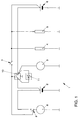
- the battery system 1 comprises a starter battery 2, a generator 3, primary consumer 4, secondary consumer 5, an on-board power supply battery 6, an ignition starter switch 7, a starter 8 with an associated switch 9.
- a circuit breaker 10 with parallel switched diode 11 arranged.
- the primary consumers 4 required for the starting process such as an engine control unit, are powered exclusively by the on-board battery 6 supplied.
- the ignition switch 7, for example by rotating the Ignition key closed, causes the on-board electrical system battery 6 via the Ignition switch 7 current flowing a closing of the switch 7, causing the Circuit between starter battery 2 and switch 8 is closed.
- the diode 11 forms a charging path between the on-board electrical system battery 6 or the generator 3 and the starter battery 2, so that a charging current via the diode 11 can flow if the voltage difference between the on-board power supply battery 6 and Starter battery 2 is greater than 0.7 V. However, if the voltage difference is smaller, then blocks diode 11 and the starter battery is protected against discharge.
- the advantage this arrangement is that the charging path via the diode does not have a separate control needed.
- this arrangement also has some disadvantages. For one, it is Charging voltage for the starter battery 2 always around the voltage drop across the diode 11 reduced. On the other hand, an engine cannot be started if the on-board electrical system battery 6 is so far discharged that it can no longer supply the primary consumers 4. The circuit breaker 10 would then have to do this before the actual starting process be closed to the on-board electrical system battery 6 via the starter battery 2 sufficient charge. To do this, however, the effort for the control unit, not shown, must be restored increase.
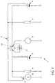
- FIG. 2 A possible solution to the problem of supplying primary consumers 4 when The starting process when the on-board electrical system battery 6 is discharged is shown in FIG. 2.
- the Primary consumer 4 connected in parallel to the starter battery 2, whereby their supply is ensured even when the on-board electrical system battery 6 is discharged.
- a disadvantage of this arrangement is that the supply to the primary consumer happens at the expense of the starter battery 2. If the charging path is blocked via diode 11 in normal operation, then it supplies the Starter battery 2, the primary consumer 4 and can be discharged.
- the charging voltage is again on the one hand reduced by the voltage drop across the diode 11 and the other divides Charging current on the starter battery 2 and the primary consumer 4, so that the Charge of starter battery 2 deteriorates in normal operation.
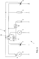
- the primary consumer 4 can have another switch 12 are assigned, by means of which the primary consumers 4 between the on-board electrical system battery 6 and starter battery 2 can be switched, which is shown in Fig. 3. there the primary consumers 4 are normally supplied via the on-board electrical system battery 6. is on the other hand, the on-board electrical system battery 6 is discharged, so the switch 12 Primary consumer 4 connected to the starter battery 2.
- a disadvantage of this arrangement is the additional switch 12.
- a measuring shunt not shown needed to record the switching conditions. Furthermore, the Charging voltage for the starter battery 2 around the voltage drop across the diode 11 reduced.
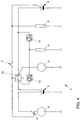
- the circuit arrangement provides a comprehensive solution to the problems 4, in which the diode 11 has been replaced by a power MOSFET 13, the Drain connection with the starter battery 2 and its source connection with the Primary consumers 4 is connected.
- the source and another power MOSFET 14 is arranged in the on-board electrical system battery 6. the preparation, the power MOSFET 13, 14 has a parasitic diode in the inverse direction, which in the Circuit arrangement is drawn in parallel to the actual transistor path.
- the MOSFETs 13, 14 have an internal current measurement, one Overcurrent protection and temperature protection. In normal operation, the MOSFET 14 is over a corresponding gate voltage is switched through and the MOSFET 13 is blocked. In In this case, the circuit works according to that in Fig. 1.
- the control unit can then terminate the charging process detect and lock the MOSFET 13 again. Is the before a start process Unload the on-board electrical system battery 6, so the control unit can do this on the basis of the current profile Detect MOSFET 14 or the voltage of the on-board electrical system battery 6 and block it. By activating the MOSFET 13, the primary consumers 4 are then switched on Starter battery 2 supplied.
- a problem with the circuit arrangement shown in FIG. 4 is that in the case of a defective, non-closing switch 10, a short-circuit current from the Vehicle battery 6 via the parasitic diodes of the MOSFETs 13, 14 to the starter battery can flow.
- the MOSFETs 13, 14, as shown in FIG. polarity reversed against each other.
- the source connection of the MOSFET 13 with the Starter battery 2 connected.
- the parasitic diode of the MOSFET 13 is in the case of defective switch 10 poled in the reverse direction and prevents unloading On-board electrical system battery 6.
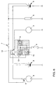
- this can be done via the diode at the appropriate potential a current from the starter battery 2 to the primary consumers 4 Flow primary consumer 4 and discharge the starter battery 2. That's why they are Pole directions of the two MOSFETs 13, 14 reversed, which is shown in Fig. 6.
- the Driving the two MOSFETs 13, 14 and the switch 10 can be how indicated schematically by a common, simply constructed control unit 15 be made.
Landscapes
- Engineering & Computer Science (AREA)
- Power Engineering (AREA)
- Chemical & Material Sciences (AREA)
- Combustion & Propulsion (AREA)
- Mechanical Engineering (AREA)
- General Engineering & Computer Science (AREA)
- Charge And Discharge Circuits For Batteries Or The Like (AREA)
- Secondary Cells (AREA)
- Hybrid Cells (AREA)
- Forklifts And Lifting Vehicles (AREA)
- Preparation Of Compounds By Using Micro-Organisms (AREA)
- Control Of Charge By Means Of Generators (AREA)
Applications Claiming Priority (2)
| Application Number | Priority Date | Filing Date | Title |
|---|---|---|---|
| DE19842657A DE19842657A1 (de) | 1998-09-17 | 1998-09-17 | Zwei-Batteriesystem |
| DE19842657 | 1998-09-17 |
Publications (3)
| Publication Number | Publication Date |
|---|---|
| EP0987146A2 true EP0987146A2 (fr) | 2000-03-22 |
| EP0987146A3 EP0987146A3 (fr) | 2005-03-30 |
| EP0987146B1 EP0987146B1 (fr) | 2006-09-27 |
Family
ID=7881316
Family Applications (1)
| Application Number | Title | Priority Date | Filing Date |
|---|---|---|---|
| EP99116818A Expired - Lifetime EP0987146B1 (fr) | 1998-09-17 | 1999-09-01 | Système à deux batteries |
Country Status (4)
| Country | Link |
|---|---|
| US (1) | US6229279B1 (fr) |
| EP (1) | EP0987146B1 (fr) |
| AT (1) | ATE340717T1 (fr) |
| DE (2) | DE19842657A1 (fr) |
Cited By (12)
| Publication number | Priority date | Publication date | Assignee | Title |
|---|---|---|---|---|
| EP0984543A2 (fr) * | 1998-09-02 | 2000-03-08 | Scania CV Aktiebolag (publ) | Système électrique pour véhicules à moteur |
| EP1245452A1 (fr) * | 2001-03-30 | 2002-10-02 | Siemens Aktiengesellschaft | Réseau de bord de véhicule, particulièrement pour un poids lourd |
| EP1297601A2 (fr) * | 2000-05-08 | 2003-04-02 | Bolder Technologies Corporation | Systeme de batteries multiples et procede associe |
| EP1396388A1 (fr) * | 2002-09-09 | 2004-03-10 | Gerd Bär GmbH | Dispositif pour le chargement d'une batterie d'un hayon élevateur d'une remorque de camion |
| EP1520752A1 (fr) * | 2003-09-30 | 2005-04-06 | Robert Bosch Gmbh | Réseau de bord à stratégie de recharge amélioré de la batterie supplémentaire et méthode correspondante |
| EP2250050A1 (fr) * | 2008-02-04 | 2010-11-17 | Scania CV AB (PUBL) | Système électrique pour un véhicule à moteur et procédé pour la commande d'un démarreur d'automobile et d'un isolateur de batterie dans un tel système électrique |
| WO2015007410A1 (fr) * | 2013-07-15 | 2015-01-22 | Auto-Kabel Management Gmbh | Montage de contacteur dans un circuit de bord de véhicule à moteur |
| WO2015059929A1 (fr) * | 2013-10-25 | 2015-04-30 | Toyota Jidosha Kabushiki Kaisha | Dispositif de fourniture d'énergie pour véhicule automobile et procédé de commande de fourniture d'énergie pour véhicule automobile monté sur un véhicule |
| EP3075989A4 (fr) * | 2013-11-27 | 2017-03-08 | Nissan Motor Co., Ltd. | Circuit électrique |
| US9802494B2 (en) | 2014-12-10 | 2017-10-31 | Volkswagen Ag | Device and method for separating and connecting two-part board networks |
| WO2019166148A1 (fr) * | 2018-02-28 | 2019-09-06 | Robert Bosch Gmbh | Borne de batterie pour réseau de bord de véhicule |
| EP4169760A1 (fr) * | 2021-10-25 | 2023-04-26 | Aptiv Technologies Limited | Circuit de distribution de l'alimentation d'un véhicule et système d'alimentation du véhicule |
Families Citing this family (63)
| Publication number | Priority date | Publication date | Assignee | Title |
|---|---|---|---|---|
| JP3450220B2 (ja) * | 1999-04-16 | 2003-09-22 | 三菱電機株式会社 | 車両用電源装置 |
| DE19941699A1 (de) * | 1999-09-02 | 2001-03-08 | Bosch Gmbh Robert | Halbleitersicherung für elektrische Verbraucher |
| DE19957478A1 (de) * | 1999-11-23 | 2001-05-31 | Volkswagen Ag | Zwei-Batteriensystem |
| DE10028748B4 (de) * | 2000-06-10 | 2009-06-04 | Bayerische Motoren Werke Aktiengesellschaft | Energieversorgungssystem für ein Kraftfahrzeug mit einem Niedrigspannungsbordnetz und mit einem Höherspannungsbordnetz |
| US6455951B1 (en) * | 2000-08-16 | 2002-09-24 | Yazaki North America, Inc. | Auto charger for system including a high voltage supply and a low voltage supply |
| JP4006948B2 (ja) * | 2001-02-14 | 2007-11-14 | スズキ株式会社 | 車両用発電制御装置 |
| NZ510958A (en) * | 2001-04-05 | 2003-11-28 | Stewart Trevor Winkle | Polarity independent jumper cables for connecting batteries in parallel |
| WO2003034523A1 (fr) * | 2001-10-11 | 2003-04-24 | Hitachi, Ltd. | Systeme de pile a combustible domestique |
| US6667591B2 (en) | 2001-10-18 | 2003-12-23 | Wayne-Dalton Corp. | Method and device for increasing the allowed motor power of a motorized garage door operator |
| JP3809549B2 (ja) * | 2001-11-22 | 2006-08-16 | 株式会社日立製作所 | 電源装置と分散型電源システムおよびこれを搭載した電気自動車 |
| ES2189696B1 (es) * | 2001-12-27 | 2004-11-16 | Lear Automotive (Eeds) Spain, S.L | Sistema de gestion de un vehiculo con doble bateria y metodo. |
| DE10256473B4 (de) * | 2002-12-03 | 2008-07-24 | Siemens Ag | Tragbare Fernbedieneinheit |
| DE10301528B4 (de) * | 2003-01-17 | 2014-07-03 | Robert Bosch Gmbh | Energiebordnetz zur Versorung eines Hochleistungsverbrauchers mit erhöhten Anforderungen an die Verfügbarkeit |
| WO2004071814A1 (fr) * | 2003-02-17 | 2004-08-26 | Denso Corporation | Systeme d'alimentation utilise sur vehicule |
| JP4120418B2 (ja) * | 2003-02-17 | 2008-07-16 | 株式会社デンソー | 自動車用電源装置 |
| US7339347B2 (en) * | 2003-08-11 | 2008-03-04 | Reserve Power Cell, Llc | Apparatus and method for reliably supplying electrical energy to an electrical system |
| US8013611B2 (en) * | 2006-07-14 | 2011-09-06 | Reserve Power Cell, Llc | Vehicle battery product and battery monitoring system |
| US7567057B2 (en) * | 2003-08-11 | 2009-07-28 | Reserve Power Cell, Llc | Multiple battery management system, auxiliary battery attachment system, and network controlled multiple battery system |
| US7011141B2 (en) * | 2003-09-02 | 2006-03-14 | General Electric Company | Apparatus and method for producing single crystal metallic objects |
| US7528579B2 (en) * | 2003-10-23 | 2009-05-05 | Schumacher Electric Corporation | System and method for charging batteries |
| US7196495B1 (en) | 2004-04-27 | 2007-03-27 | Concord Technologies, Lp | Dual battery and monitor arrangement |
| GB2415839B (en) * | 2004-06-29 | 2007-08-29 | Ford Global Tech Llc | Dual battery vehicle electrical systems |
| US7362005B2 (en) * | 2005-03-10 | 2008-04-22 | Red Tech Inc. | Isolated dual battery system |
| US7598700B2 (en) * | 2005-03-30 | 2009-10-06 | Reserve Power Cell, Llc | Tamper resistant battery and battery warranty and performance tracking system |
| CA2647638A1 (fr) * | 2005-05-05 | 2006-11-16 | Afs Trinity Power Corporation | Vehicule hybride enfichable a stockage d'energie rapide |
| FR2893770B1 (fr) * | 2005-11-24 | 2008-08-29 | Valeo Equip Electr Moteur | Dispositif de gestion d'alimentation d'un reseau de consommateurs pour vehicule automobile |
| JP4449940B2 (ja) * | 2006-05-16 | 2010-04-14 | トヨタ自動車株式会社 | 車両用二電源システム |
| DE102007062955B4 (de) | 2007-12-21 | 2011-06-01 | Catem Develec Gmbh & Co. Kg | Schaltung zur Spannungsstabilisierung eines Bordnetzes |
| DE212009000046U1 (de) * | 2008-04-21 | 2010-12-09 | International Truck Intellectual Property Co., LLC, Warrenville | Mehrfachbatteriesystem für ein Kraftfahrzeug |
| US8076797B2 (en) * | 2008-05-15 | 2011-12-13 | Indy Power Systems Llc | Energy transfer circuit and method |
| DE102009005511B4 (de) | 2009-01-20 | 2015-04-02 | Volkswagen Ag | Kraftfahrzeug-Bordnetz |
| US20110012423A1 (en) * | 2009-07-15 | 2011-01-20 | International Truck Intellectual Property Company,Llc | Motor vehicle having plural battery banks |
| WO2011014593A2 (fr) * | 2009-07-31 | 2011-02-03 | Thermo King Corporation | Convertisseur de tension de batterie bi-directionnel |
| JP5234052B2 (ja) * | 2010-04-27 | 2013-07-10 | 株式会社デンソー | 電源装置 |
| US8981710B2 (en) | 2010-09-20 | 2015-03-17 | Indy Power Systems Llc | Energy management system |
| SE535351C2 (sv) | 2010-11-01 | 2012-07-03 | Scania Cv Ab | Aktiveringsanordning samt aktiveringsmetod för ett dubbelbatterisystem |
| CN102910082B (zh) * | 2011-08-05 | 2015-03-25 | 微宏动力系统(湖州)有限公司 | 电动汽车主辅电源切换系统 |
| KR20130096782A (ko) * | 2012-02-23 | 2013-09-02 | 에스케이이노베이션 주식회사 | 차량 시동 전용 장치 |
| US9425727B2 (en) * | 2012-04-17 | 2016-08-23 | Kohler Co. | Charging an energy storage device with a variable speed generator |
| US9219294B2 (en) | 2012-08-22 | 2015-12-22 | Eric D. Albsmeier | Power management system that changes the operating conditions of a battery charger |
| US9331498B2 (en) * | 2012-09-07 | 2016-05-03 | Kohler Co. | Power generation system that provides efficient battery charger selection |
| US8829855B2 (en) * | 2012-09-26 | 2014-09-09 | Kohler Co. | Power generation system that optimizes the power provided to start a generator |
| DE102013013369B4 (de) * | 2013-07-15 | 2022-05-05 | Auto-Kabel Management Gmbh | System und Verfahren zum Ansteuern eines elektronischen Schalters |
| US9527402B2 (en) | 2014-01-23 | 2016-12-27 | Johnson Controls Technology Company | Switched passive architectures for batteries having two different chemistries |
| US9718375B2 (en) | 2014-01-23 | 2017-08-01 | Johnson Controls Technology Company | Passive architectures for batteries having two different chemistries |
| CN105431975B (zh) | 2013-07-31 | 2018-11-23 | 约翰逊控制技术公司 | 用于具有两种不同化学成分的蓄电池的开关无源结构 |
| US9527401B2 (en) | 2014-01-23 | 2016-12-27 | Johnson Controls Technology Company | Semi-active architectures for batteries having two different chemistries |
| US9812949B2 (en) | 2013-10-10 | 2017-11-07 | Indy Power Systems Llc | Poly-phase inverter with independent phase control |
| JP6221796B2 (ja) * | 2014-02-07 | 2017-11-01 | 株式会社デンソー | 電池ユニット及び電源システム |
| DE102014203030B4 (de) * | 2014-02-19 | 2021-06-02 | Vitesco Technologies GmbH | Verfahren zum gesteuerten Verbinden mehrerer Bordnetzzweige eines Fahrzeugs, Steuereinheit zur Ausführung des Verfahrens sowie Fahrzeugbordnetz |
| US9461482B2 (en) * | 2014-04-15 | 2016-10-04 | Win Sheng Cheng | Multi-chemistry battery pack system |
| US9803609B2 (en) | 2014-04-22 | 2017-10-31 | Maxwell Technologies, Inc. | System and methods for improved starting of combustion engines |
| US10320202B2 (en) * | 2014-09-30 | 2019-06-11 | Johnson Controls Technology Company | Battery system bi-stable relay control |
| FR3026903B1 (fr) * | 2014-10-03 | 2018-03-23 | Psa Automobiles Sa. | Dispositif de gestion de transfert d'energie ameliore |
| US9969292B2 (en) | 2014-11-14 | 2018-05-15 | Johnson Controls Technology Company | Semi-active partial parallel battery architecture for an automotive vehicle systems and methods |
| US9452672B2 (en) * | 2014-12-30 | 2016-09-27 | GM Global Technology Operations LLC | Vehicle powertrain |
| JP6828296B2 (ja) * | 2016-08-09 | 2021-02-10 | 株式会社Gsユアサ | 蓄電装置および蓄電装置の充電制御方法 |
| JP6665757B2 (ja) * | 2016-11-08 | 2020-03-13 | 株式会社デンソー | 電源制御装置、及び電池ユニット |
| US11233419B2 (en) | 2017-08-10 | 2022-01-25 | Zoox, Inc. | Smart battery circuit |
| JP7189693B2 (ja) * | 2018-07-13 | 2022-12-14 | 株式会社Subaru | 電源システム |
| CA3128246A1 (fr) | 2019-02-05 | 2020-08-13 | Redarc Technologies Pty Ltd | Systeme de batterie double |
| US11750021B2 (en) | 2020-11-13 | 2023-09-05 | Raytheon Company | Modular electrical power subsystem architecture |
| KR20230022342A (ko) * | 2021-08-06 | 2023-02-15 | 현대자동차주식회사 | 하이브리드 차량의 듀얼 배터리 제어 방법 |
Citations (1)
| Publication number | Priority date | Publication date | Assignee | Title |
|---|---|---|---|---|
| DE4028242A1 (de) | 1990-09-06 | 1992-03-12 | Bayerische Motoren Werke Ag | Zwei batteriensystem |
Family Cites Families (8)
| Publication number | Priority date | Publication date | Assignee | Title |
|---|---|---|---|---|
| DE3841769C1 (en) | 1988-12-12 | 1990-06-07 | Juergen 8014 Neubiberg De Wemhoener | Circuit for ensuring the provision of starting energy in motor vehicles with internal combustion engines |
| US5325038A (en) | 1991-06-10 | 1994-06-28 | Nippondenso Co., Ltd. | Driving apparatus for controlling an electric load in a vehicle |
| US5316868A (en) * | 1992-07-21 | 1994-05-31 | Globe-Union, Inc. | Dual battery switch circuit |
| US5488283A (en) * | 1993-09-28 | 1996-01-30 | Globe-Union, Inc. | Vehicle battery system providing battery back-up and opportunity charging |
| NZ264225A (en) * | 1994-08-11 | 1998-07-28 | Glorywin Int Group Ltd | Vehicle battery switch with state of charge sensing circuit |
| FR2729901B1 (fr) * | 1995-01-30 | 1997-04-18 | Valeo Equip Electr Moteur | Unite de gestion d'energie pour reseau electrique de vehicule automobile incorporant plusieurs unites de stockage d'energie, et reseau electrique incorporant une telle unite de gestion d'energie |
| DE19651612B4 (de) | 1996-12-12 | 2012-09-27 | Robert Bosch Gmbh | Elektronische Schaltung zur Spannungsversorgung |
| US5764032A (en) * | 1997-03-06 | 1998-06-09 | Maxim Integrated Products, Inc. | Multiple battery switchover circuits |
-
1998
- 1998-09-17 DE DE19842657A patent/DE19842657A1/de not_active Ceased
-
1999
- 1999-09-01 AT AT99116818T patent/ATE340717T1/de not_active IP Right Cessation
- 1999-09-01 EP EP99116818A patent/EP0987146B1/fr not_active Expired - Lifetime
- 1999-09-01 DE DE59913876T patent/DE59913876D1/de not_active Expired - Lifetime
- 1999-09-16 US US09/397,204 patent/US6229279B1/en not_active Expired - Lifetime
Patent Citations (1)
| Publication number | Priority date | Publication date | Assignee | Title |
|---|---|---|---|---|
| DE4028242A1 (de) | 1990-09-06 | 1992-03-12 | Bayerische Motoren Werke Ag | Zwei batteriensystem |
Cited By (20)
| Publication number | Priority date | Publication date | Assignee | Title |
|---|---|---|---|---|
| EP0984543A2 (fr) * | 1998-09-02 | 2000-03-08 | Scania CV Aktiebolag (publ) | Système électrique pour véhicules à moteur |
| EP0984543A3 (fr) * | 1998-09-02 | 2004-01-21 | Scania CV Aktiebolag (publ) | Système électrique pour véhicules à moteur |
| EP1297601A2 (fr) * | 2000-05-08 | 2003-04-02 | Bolder Technologies Corporation | Systeme de batteries multiples et procede associe |
| EP1297601A4 (fr) * | 2000-05-08 | 2005-03-23 | Bolder Technologies Corp | Systeme de batteries multiples et procede associe |
| EP1245452A1 (fr) * | 2001-03-30 | 2002-10-02 | Siemens Aktiengesellschaft | Réseau de bord de véhicule, particulièrement pour un poids lourd |
| US6718927B2 (en) | 2001-03-30 | 2004-04-13 | Siemens Aktiengesellschaft | Vehicle electrical system, particularly for a truck |
| EP1396388A1 (fr) * | 2002-09-09 | 2004-03-10 | Gerd Bär GmbH | Dispositif pour le chargement d'une batterie d'un hayon élevateur d'une remorque de camion |
| EP1520752A1 (fr) * | 2003-09-30 | 2005-04-06 | Robert Bosch Gmbh | Réseau de bord à stratégie de recharge amélioré de la batterie supplémentaire et méthode correspondante |
| EP2250050A1 (fr) * | 2008-02-04 | 2010-11-17 | Scania CV AB (PUBL) | Système électrique pour un véhicule à moteur et procédé pour la commande d'un démarreur d'automobile et d'un isolateur de batterie dans un tel système électrique |
| EP2250050A4 (fr) * | 2008-02-04 | 2013-10-02 | Scania Cv Abp | Système électrique pour un véhicule à moteur et procédé pour la commande d'un démarreur d'automobile et d'un isolateur de batterie dans un tel système électrique |
| WO2015007410A1 (fr) * | 2013-07-15 | 2015-01-22 | Auto-Kabel Management Gmbh | Montage de contacteur dans un circuit de bord de véhicule à moteur |
| US9644594B2 (en) | 2013-07-15 | 2017-05-09 | Auto-Kabel Management Gmbh | Switch arrangement in a motor vehicle electrical system |
| WO2015059929A1 (fr) * | 2013-10-25 | 2015-04-30 | Toyota Jidosha Kabushiki Kaisha | Dispositif de fourniture d'énergie pour véhicule automobile et procédé de commande de fourniture d'énergie pour véhicule automobile monté sur un véhicule |
| EP3075989A4 (fr) * | 2013-11-27 | 2017-03-08 | Nissan Motor Co., Ltd. | Circuit électrique |
| US9944199B2 (en) | 2013-11-27 | 2018-04-17 | Nissan Motor Co., Ltd. | Electric circuit |
| US9802494B2 (en) | 2014-12-10 | 2017-10-31 | Volkswagen Ag | Device and method for separating and connecting two-part board networks |
| WO2019166148A1 (fr) * | 2018-02-28 | 2019-09-06 | Robert Bosch Gmbh | Borne de batterie pour réseau de bord de véhicule |
| JP2021513727A (ja) * | 2018-02-28 | 2021-05-27 | ロベルト・ボッシュ・ゲゼルシャフト・ミト・ベシュレンクテル・ハフツングRobert Bosch Gmbh | 車両オンボードネットワーク用のバッテリー端子 |
| US11292405B2 (en) | 2018-02-28 | 2022-04-05 | Robert Bosch Gmbh | Battery terminal with a star-point connection switch configuration for a vehicle electrical system |
| EP4169760A1 (fr) * | 2021-10-25 | 2023-04-26 | Aptiv Technologies Limited | Circuit de distribution de l'alimentation d'un véhicule et système d'alimentation du véhicule |
Also Published As
| Publication number | Publication date |
|---|---|
| DE19842657A1 (de) | 2000-03-23 |
| DE59913876D1 (de) | 2006-11-09 |
| EP0987146A3 (fr) | 2005-03-30 |
| US6229279B1 (en) | 2001-05-08 |
| EP0987146B1 (fr) | 2006-09-27 |
| ATE340717T1 (de) | 2006-10-15 |
Similar Documents
| Publication | Publication Date | Title |
|---|---|---|
| EP0987146B1 (fr) | Système à deux batteries | |
| EP1232073B1 (fr) | Systeme a deux batteries | |
| EP0850506B1 (fr) | Dispositif d'alimentation en courant dans un vehicule automobile | |
| DE10014243B4 (de) | Zwei-Batteriensystem | |
| EP1561269B1 (fr) | Reseau de bord destine a alimenter au moins un recepteur presentant des exigences elevees en matiere de disponibilite du reseau de bord | |
| EP0987145B1 (fr) | Système à deux batteries | |
| DE19734598C1 (de) | Sicherheitsrelevantes System, wie z. B. eine elektrische Bremsanlage oder eine elektrische Lenkanlage für ein Kraftfahrzeug | |
| DE3841769C1 (en) | Circuit for ensuring the provision of starting energy in motor vehicles with internal combustion engines | |
| WO1998019890A1 (fr) | Commande de reseau d'alimentation electrique de bord | |
| DE2919022A1 (de) | Verpolschutzanordnung fuer ein batterieladesystem | |
| DE19929246C2 (de) | Batteriesystem | |
| EP0878889A2 (fr) | Dispositif d'alimentation énergie électrique pour un véhicule militaire, en particulier un char muni d'une tourrelle | |
| DE102015008005B4 (de) | Notlaufbetrieb für ein Kraftfahrzeug mit zwei Bordnetzen | |
| EP3820733B1 (fr) | Dispositif de batterie multi-tension et réseau de bord pour un véhicule automobile | |
| DE102010020295A1 (de) | Schaltungsanordnung zum Schützen einer Batterie bei Verpolung | |
| DE69811190T2 (de) | Regelvorrichtung für Kraftfahrzeuganlasser | |
| WO2020109134A1 (fr) | La présente invention concerne un dispositif de coupure pour un système d'accumulateurs d'énergie électrochimiques comportant au moins un accumulateur d'énergie électrochimique ayant un premier et un second pôle de branchement ainsi qu'un premier et un second branchement de conducteur électrique, comportant un premier chemin de courant entre le premier pôle de branchement de l'accumulateur d'énergie électrochimique et le premier branchement de conducteur électrique avec un premier commutateur semi-conducteur, et un élément de coupure monté en série avec le premier commutateur semi-conducteur ; et un deuxième chemin de courant avec un deuxième commutateur semi-conducteur qui est relié électriquement au premier chemin de courant au moyen d'une première dérivation de courant entre le premier commutateur semi-conducteur et l'élément de coupure monté en série et le second pôle de branchement de l'accumulateur d'énergie ; et un troisième chemin de courant avec un troisième commutateur semi-conducteur, qui est relié électriquement au premier chemin de courant au moyen d'une seconde dérivation de courant entre l'élément de coupure et le premier branchement de conducteur électrique et le second pôle de branchement de l'accumulateur d'énergie électrochimique. par différents états de commutation des commutateurs semi-conducteurs, un cas de défaillance d'au moins un des commutateurs semi-conducteurs est détecté et, par le déclenchement de l'élément de coupure, l'accumulateur d'énergie électrochimique est séparé d'au moins un branchement de conducteur électrique. | |
| WO2020007617A1 (fr) | Système de batterie multi-tension et réseau de bord multi-tension pour véhicule automobile | |
| DE69615718T2 (de) | Sicherheitstrennungsschalter zur automatischen Trennung elektrischer Lasten in Kraftfahrzeugen oder dergleichen | |
| DE102012024738A1 (de) | Energiespeichervorrichtung und Fahrzeug | |
| DE102015007629A1 (de) | Bordnetz für ein Kraftfahrzeug | |
| EP1541423B1 (fr) | Réseau de bord pour véhicules | |
| DE102021200578A1 (de) | Kraftfahrzeugbordnetz | |
| DE102021001509A1 (de) | Bordnetz und Betriebsverfahren für dasselbe | |
| DE102021002080A1 (de) | Kraftfahrzeug mit Bordnetz |
Legal Events
| Date | Code | Title | Description |
|---|---|---|---|
| PUAI | Public reference made under article 153(3) epc to a published international application that has entered the european phase |
Free format text: ORIGINAL CODE: 0009012 |
|
| AK | Designated contracting states |
Kind code of ref document: A2 Designated state(s): AT BE CH CY DE DK ES FI FR GB GR IE IT LI LU MC NL PT SE |
|
| AX | Request for extension of the european patent |
Free format text: AL;LT;LV;MK;RO;SI |
|
| PUAL | Search report despatched |
Free format text: ORIGINAL CODE: 0009013 |
|
| AK | Designated contracting states |
Kind code of ref document: A3 Designated state(s): AT BE CH CY DE DK ES FI FR GB GR IE IT LI LU MC NL PT SE |
|
| AX | Request for extension of the european patent |
Extension state: AL LT LV MK RO SI |
|
| RIC1 | Information provided on ipc code assigned before grant |
Ipc: 7H 02J 7/14 B Ipc: 7B 60R 16/02 A |
|
| 17P | Request for examination filed |
Effective date: 20050930 |
|
| AKX | Designation fees paid |
Designated state(s): AT BE CH CY DE DK ES FI FR GB GR IE IT LI LU MC NL PT SE |
|
| GRAP | Despatch of communication of intention to grant a patent |
Free format text: ORIGINAL CODE: EPIDOSNIGR1 |
|
| GRAS | Grant fee paid |
Free format text: ORIGINAL CODE: EPIDOSNIGR3 |
|
| GRAA | (expected) grant |
Free format text: ORIGINAL CODE: 0009210 |
|
| AK | Designated contracting states |
Kind code of ref document: B1 Designated state(s): AT BE CH CY DE DK ES FI FR GB GR IE IT LI LU MC NL PT SE |
|
| PG25 | Lapsed in a contracting state [announced via postgrant information from national office to epo] |
Ref country code: NL Free format text: LAPSE BECAUSE OF FAILURE TO SUBMIT A TRANSLATION OF THE DESCRIPTION OR TO PAY THE FEE WITHIN THE PRESCRIBED TIME-LIMIT Effective date: 20060927 Ref country code: IT Free format text: LAPSE BECAUSE OF FAILURE TO SUBMIT A TRANSLATION OF THE DESCRIPTION OR TO PAY THE FEE WITHIN THE PRESCRIBED TIME-LIMIT;WARNING: LAPSES OF ITALIAN PATENTS WITH EFFECTIVE DATE BEFORE 2007 MAY HAVE OCCURRED AT ANY TIME BEFORE 2007. THE CORRECT EFFECTIVE DATE MAY BE DIFFERENT FROM THE ONE RECORDED. Effective date: 20060927 Ref country code: IE Free format text: LAPSE BECAUSE OF FAILURE TO SUBMIT A TRANSLATION OF THE DESCRIPTION OR TO PAY THE FEE WITHIN THE PRESCRIBED TIME-LIMIT Effective date: 20060927 Ref country code: FI Free format text: LAPSE BECAUSE OF FAILURE TO SUBMIT A TRANSLATION OF THE DESCRIPTION OR TO PAY THE FEE WITHIN THE PRESCRIBED TIME-LIMIT Effective date: 20060927 |
|
| REG | Reference to a national code |
Ref country code: GB Ref legal event code: FG4D Free format text: NOT ENGLISH |
|
| REG | Reference to a national code |
Ref country code: CH Ref legal event code: EP |
|
| REG | Reference to a national code |
Ref country code: IE Ref legal event code: FG4D Free format text: LANGUAGE OF EP DOCUMENT: GERMAN |
|
| REF | Corresponds to: |
Ref document number: 59913876 Country of ref document: DE Date of ref document: 20061109 Kind code of ref document: P |
|
| PG25 | Lapsed in a contracting state [announced via postgrant information from national office to epo] |
Ref country code: SE Free format text: LAPSE BECAUSE OF FAILURE TO SUBMIT A TRANSLATION OF THE DESCRIPTION OR TO PAY THE FEE WITHIN THE PRESCRIBED TIME-LIMIT Effective date: 20061227 Ref country code: DK Free format text: LAPSE BECAUSE OF FAILURE TO SUBMIT A TRANSLATION OF THE DESCRIPTION OR TO PAY THE FEE WITHIN THE PRESCRIBED TIME-LIMIT Effective date: 20061227 |
|
| PG25 | Lapsed in a contracting state [announced via postgrant information from national office to epo] |
Ref country code: ES Free format text: LAPSE BECAUSE OF FAILURE TO SUBMIT A TRANSLATION OF THE DESCRIPTION OR TO PAY THE FEE WITHIN THE PRESCRIBED TIME-LIMIT Effective date: 20070107 |
|
| GBT | Gb: translation of ep patent filed (gb section 77(6)(a)/1977) |
Effective date: 20070103 |
|
| NLV1 | Nl: lapsed or annulled due to failure to fulfill the requirements of art. 29p and 29m of the patents act | ||
| PG25 | Lapsed in a contracting state [announced via postgrant information from national office to epo] |
Ref country code: PT Free format text: LAPSE BECAUSE OF FAILURE TO SUBMIT A TRANSLATION OF THE DESCRIPTION OR TO PAY THE FEE WITHIN THE PRESCRIBED TIME-LIMIT Effective date: 20070313 |
|
| REG | Reference to a national code |
Ref country code: IE Ref legal event code: FD4D |
|
| EN | Fr: translation not filed | ||
| PLBE | No opposition filed within time limit |
Free format text: ORIGINAL CODE: 0009261 |
|
| STAA | Information on the status of an ep patent application or granted ep patent |
Free format text: STATUS: NO OPPOSITION FILED WITHIN TIME LIMIT |
|
| 26N | No opposition filed |
Effective date: 20070628 |
|
| BERE | Be: lapsed |
Owner name: VOLKSWAGEN A.G. Effective date: 20070930 |
|
| PG25 | Lapsed in a contracting state [announced via postgrant information from national office to epo] |
Ref country code: MC Free format text: LAPSE BECAUSE OF NON-PAYMENT OF DUE FEES Effective date: 20070930 Ref country code: GR Free format text: LAPSE BECAUSE OF FAILURE TO SUBMIT A TRANSLATION OF THE DESCRIPTION OR TO PAY THE FEE WITHIN THE PRESCRIBED TIME-LIMIT Effective date: 20061228 Ref country code: FR Free format text: LAPSE BECAUSE OF FAILURE TO SUBMIT A TRANSLATION OF THE DESCRIPTION OR TO PAY THE FEE WITHIN THE PRESCRIBED TIME-LIMIT Effective date: 20070525 |
|
| REG | Reference to a national code |
Ref country code: CH Ref legal event code: PL |
|
| PG25 | Lapsed in a contracting state [announced via postgrant information from national office to epo] |
Ref country code: LI Free format text: LAPSE BECAUSE OF NON-PAYMENT OF DUE FEES Effective date: 20070930 Ref country code: CH Free format text: LAPSE BECAUSE OF NON-PAYMENT OF DUE FEES Effective date: 20070930 |
|
| PG25 | Lapsed in a contracting state [announced via postgrant information from national office to epo] |
Ref country code: BE Free format text: LAPSE BECAUSE OF NON-PAYMENT OF DUE FEES Effective date: 20070930 |
|
| PG25 | Lapsed in a contracting state [announced via postgrant information from national office to epo] |
Ref country code: FR Free format text: LAPSE BECAUSE OF FAILURE TO SUBMIT A TRANSLATION OF THE DESCRIPTION OR TO PAY THE FEE WITHIN THE PRESCRIBED TIME-LIMIT Effective date: 20060927 Ref country code: AT Free format text: LAPSE BECAUSE OF NON-PAYMENT OF DUE FEES Effective date: 20070901 |
|
| PG25 | Lapsed in a contracting state [announced via postgrant information from national office to epo] |
Ref country code: LU Free format text: LAPSE BECAUSE OF NON-PAYMENT OF DUE FEES Effective date: 20070901 Ref country code: CY Free format text: LAPSE BECAUSE OF FAILURE TO SUBMIT A TRANSLATION OF THE DESCRIPTION OR TO PAY THE FEE WITHIN THE PRESCRIBED TIME-LIMIT Effective date: 20060927 |
|
| PGFP | Annual fee paid to national office [announced via postgrant information from national office to epo] |
Ref country code: GB Payment date: 20180928 Year of fee payment: 20 |
|
| PGFP | Annual fee paid to national office [announced via postgrant information from national office to epo] |
Ref country code: DE Payment date: 20180930 Year of fee payment: 20 |
|
| REG | Reference to a national code |
Ref country code: DE Ref legal event code: R071 Ref document number: 59913876 Country of ref document: DE |
|
| REG | Reference to a national code |
Ref country code: GB Ref legal event code: PE20 Expiry date: 20190831 |
|
| PG25 | Lapsed in a contracting state [announced via postgrant information from national office to epo] |
Ref country code: GB Free format text: LAPSE BECAUSE OF EXPIRATION OF PROTECTION Effective date: 20190831 |
|
| P01 | Opt-out of the competence of the unified patent court (upc) registered |
Effective date: 20230523 |