EP0987146A2 - Two-battery system - Google Patents
Two-battery system Download PDFInfo
- Publication number
- EP0987146A2 EP0987146A2 EP99116818A EP99116818A EP0987146A2 EP 0987146 A2 EP0987146 A2 EP 0987146A2 EP 99116818 A EP99116818 A EP 99116818A EP 99116818 A EP99116818 A EP 99116818A EP 0987146 A2 EP0987146 A2 EP 0987146A2
- Authority
- EP
- European Patent Office
- Prior art keywords
- battery
- starter
- electrical system
- mosfet
- board electrical
- Prior art date
- Legal status (The legal status is an assumption and is not a legal conclusion. Google has not performed a legal analysis and makes no representation as to the accuracy of the status listed.)
- Granted
Links
Images

Classifications
-
- H—ELECTRICITY
- H02—GENERATION; CONVERSION OR DISTRIBUTION OF ELECTRIC POWER
- H02J—CIRCUIT ARRANGEMENTS OR SYSTEMS FOR SUPPLYING OR DISTRIBUTING ELECTRIC POWER; SYSTEMS FOR STORING ELECTRIC ENERGY
- H02J7/00—Circuit arrangements for charging or depolarising batteries or for supplying loads from batteries
- H02J7/14—Circuit arrangements for charging or depolarising batteries or for supplying loads from batteries for charging batteries from dynamo-electric generators driven at varying speed, e.g. on vehicle
- H02J7/1423—Circuit arrangements for charging or depolarising batteries or for supplying loads from batteries for charging batteries from dynamo-electric generators driven at varying speed, e.g. on vehicle with multiple batteries
-
- F—MECHANICAL ENGINEERING; LIGHTING; HEATING; WEAPONS; BLASTING
- F02—COMBUSTION ENGINES; HOT-GAS OR COMBUSTION-PRODUCT ENGINE PLANTS
- F02N—STARTING OF COMBUSTION ENGINES; STARTING AIDS FOR SUCH ENGINES, NOT OTHERWISE PROVIDED FOR
- F02N11/00—Starting of engines by means of electric motors
- F02N11/08—Circuits or control means specially adapted for starting of engines
- F02N11/0862—Circuits or control means specially adapted for starting of engines characterised by the electrical power supply means, e.g. battery
- F02N11/0866—Circuits or control means specially adapted for starting of engines characterised by the electrical power supply means, e.g. battery comprising several power sources, e.g. battery and capacitor or two batteries
-
- H—ELECTRICITY
- H02—GENERATION; CONVERSION OR DISTRIBUTION OF ELECTRIC POWER
- H02J—CIRCUIT ARRANGEMENTS OR SYSTEMS FOR SUPPLYING OR DISTRIBUTING ELECTRIC POWER; SYSTEMS FOR STORING ELECTRIC ENERGY
- H02J7/00—Circuit arrangements for charging or depolarising batteries or for supplying loads from batteries
- H02J7/0013—Circuit arrangements for charging or depolarising batteries or for supplying loads from batteries acting upon several batteries simultaneously or sequentially
- H02J7/0025—Sequential battery discharge in systems with a plurality of batteries
-
- B—PERFORMING OPERATIONS; TRANSPORTING
- B60—VEHICLES IN GENERAL
- B60R—VEHICLES, VEHICLE FITTINGS, OR VEHICLE PARTS, NOT OTHERWISE PROVIDED FOR
- B60R16/00—Electric or fluid circuits specially adapted for vehicles and not otherwise provided for; Arrangement of elements of electric or fluid circuits specially adapted for vehicles and not otherwise provided for
- B60R16/02—Electric or fluid circuits specially adapted for vehicles and not otherwise provided for; Arrangement of elements of electric or fluid circuits specially adapted for vehicles and not otherwise provided for electric constitutive elements
- B60R16/03—Electric or fluid circuits specially adapted for vehicles and not otherwise provided for; Arrangement of elements of electric or fluid circuits specially adapted for vehicles and not otherwise provided for electric constitutive elements for supply of electrical power to vehicle subsystems or for
-
- H—ELECTRICITY
- H02—GENERATION; CONVERSION OR DISTRIBUTION OF ELECTRIC POWER
- H02J—CIRCUIT ARRANGEMENTS OR SYSTEMS FOR SUPPLYING OR DISTRIBUTING ELECTRIC POWER; SYSTEMS FOR STORING ELECTRIC ENERGY
- H02J2310/00—The network for supplying or distributing electric power characterised by its spatial reach or by the load
- H02J2310/40—The network being an on-board power network, i.e. within a vehicle
- H02J2310/46—The network being an on-board power network, i.e. within a vehicle for ICE-powered road vehicles
-
- Y—GENERAL TAGGING OF NEW TECHNOLOGICAL DEVELOPMENTS; GENERAL TAGGING OF CROSS-SECTIONAL TECHNOLOGIES SPANNING OVER SEVERAL SECTIONS OF THE IPC; TECHNICAL SUBJECTS COVERED BY FORMER USPC CROSS-REFERENCE ART COLLECTIONS [XRACs] AND DIGESTS
- Y02—TECHNOLOGIES OR APPLICATIONS FOR MITIGATION OR ADAPTATION AGAINST CLIMATE CHANGE
- Y02T—CLIMATE CHANGE MITIGATION TECHNOLOGIES RELATED TO TRANSPORTATION
- Y02T10/00—Road transport of goods or passengers
- Y02T10/60—Other road transportation technologies with climate change mitigation effect
- Y02T10/70—Energy storage systems for electromobility, e.g. batteries
Definitions
- the invention relates to a two-battery system and a method for controlling the Two-battery system.
- Such a two-battery system is known from DE 40 28 242 A1, the one Starter battery and an electrical system battery includes. Between the starter battery and the On-board electrical system battery is a starter battery switch arranged during a starting process is closed so that the two batteries are connected. The Supply of primary consumers and secondary consumers then takes place via both Batteries instead. Primary consumers are those for starting and driving ability or vehicle safety essential consumers and among secondary consumers Understand comfort components. To prevent the starter battery from discharging, a control unit detects the state of charge of the starter battery and the on-board electrical system battery.
- the invention is therefore based on the technical problem of a two-battery system create, in which the starter battery only loads in the starting phase, the starter battery however, at any time if the load state allows, can be loaded and only one low circuitry required.
- a switch arranged with the optional before starting the supply of primary consumers between the on-board electrical system battery and the Starter battery can be switched, this switch preferably also is designed as a MOSFET.
- the two MOSFETs are preferably reversed, so that either in each case the two source or drain connections are connected to one another, so that no short-circuit path can arise via the parasitic diodes of the MOSFETs.
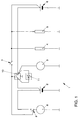
- the battery system 1 comprises a starter battery 2, a generator 3, primary consumer 4, secondary consumer 5, an on-board power supply battery 6, an ignition starter switch 7, a starter 8 with an associated switch 9.
- a circuit breaker 10 with parallel switched diode 11 arranged.
- the primary consumers 4 required for the starting process such as an engine control unit, are powered exclusively by the on-board battery 6 supplied.
- the ignition switch 7, for example by rotating the Ignition key closed, causes the on-board electrical system battery 6 via the Ignition switch 7 current flowing a closing of the switch 7, causing the Circuit between starter battery 2 and switch 8 is closed.
- the diode 11 forms a charging path between the on-board electrical system battery 6 or the generator 3 and the starter battery 2, so that a charging current via the diode 11 can flow if the voltage difference between the on-board power supply battery 6 and Starter battery 2 is greater than 0.7 V. However, if the voltage difference is smaller, then blocks diode 11 and the starter battery is protected against discharge.
- the advantage this arrangement is that the charging path via the diode does not have a separate control needed.
- this arrangement also has some disadvantages. For one, it is Charging voltage for the starter battery 2 always around the voltage drop across the diode 11 reduced. On the other hand, an engine cannot be started if the on-board electrical system battery 6 is so far discharged that it can no longer supply the primary consumers 4. The circuit breaker 10 would then have to do this before the actual starting process be closed to the on-board electrical system battery 6 via the starter battery 2 sufficient charge. To do this, however, the effort for the control unit, not shown, must be restored increase.
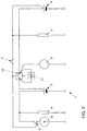
- FIG. 2 A possible solution to the problem of supplying primary consumers 4 when The starting process when the on-board electrical system battery 6 is discharged is shown in FIG. 2.
- the Primary consumer 4 connected in parallel to the starter battery 2, whereby their supply is ensured even when the on-board electrical system battery 6 is discharged.
- a disadvantage of this arrangement is that the supply to the primary consumer happens at the expense of the starter battery 2. If the charging path is blocked via diode 11 in normal operation, then it supplies the Starter battery 2, the primary consumer 4 and can be discharged.
- the charging voltage is again on the one hand reduced by the voltage drop across the diode 11 and the other divides Charging current on the starter battery 2 and the primary consumer 4, so that the Charge of starter battery 2 deteriorates in normal operation.
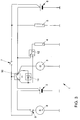
- the primary consumer 4 can have another switch 12 are assigned, by means of which the primary consumers 4 between the on-board electrical system battery 6 and starter battery 2 can be switched, which is shown in Fig. 3. there the primary consumers 4 are normally supplied via the on-board electrical system battery 6. is on the other hand, the on-board electrical system battery 6 is discharged, so the switch 12 Primary consumer 4 connected to the starter battery 2.
- a disadvantage of this arrangement is the additional switch 12.
- a measuring shunt not shown needed to record the switching conditions. Furthermore, the Charging voltage for the starter battery 2 around the voltage drop across the diode 11 reduced.
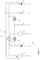
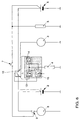
- the circuit arrangement provides a comprehensive solution to the problems 4, in which the diode 11 has been replaced by a power MOSFET 13, the Drain connection with the starter battery 2 and its source connection with the Primary consumers 4 is connected.
- the source and another power MOSFET 14 is arranged in the on-board electrical system battery 6. the preparation, the power MOSFET 13, 14 has a parasitic diode in the inverse direction, which in the Circuit arrangement is drawn in parallel to the actual transistor path.
- the MOSFETs 13, 14 have an internal current measurement, one Overcurrent protection and temperature protection. In normal operation, the MOSFET 14 is over a corresponding gate voltage is switched through and the MOSFET 13 is blocked. In In this case, the circuit works according to that in Fig. 1.
- the control unit can then terminate the charging process detect and lock the MOSFET 13 again. Is the before a start process Unload the on-board electrical system battery 6, so the control unit can do this on the basis of the current profile Detect MOSFET 14 or the voltage of the on-board electrical system battery 6 and block it. By activating the MOSFET 13, the primary consumers 4 are then switched on Starter battery 2 supplied.
- a problem with the circuit arrangement shown in FIG. 4 is that in the case of a defective, non-closing switch 10, a short-circuit current from the Vehicle battery 6 via the parasitic diodes of the MOSFETs 13, 14 to the starter battery can flow.
- the MOSFETs 13, 14, as shown in FIG. polarity reversed against each other.
- the source connection of the MOSFET 13 with the Starter battery 2 connected.
- the parasitic diode of the MOSFET 13 is in the case of defective switch 10 poled in the reverse direction and prevents unloading On-board electrical system battery 6.
- this can be done via the diode at the appropriate potential a current from the starter battery 2 to the primary consumers 4 Flow primary consumer 4 and discharge the starter battery 2. That's why they are Pole directions of the two MOSFETs 13, 14 reversed, which is shown in Fig. 6.
- the Driving the two MOSFETs 13, 14 and the switch 10 can be how indicated schematically by a common, simply constructed control unit 15 be made.
Abstract
Description
Die Erfindung betrifft ein Zwei-Batteriesystem und ein Verfahren zur Ansteuerung des Zwei-Batteriesystems.The invention relates to a two-battery system and a method for controlling the Two-battery system.
Ein derartiges Zwei-Batteriesystem ist aus der DE 40 28 242 A1 bekannt, das eine Starterbatterie und eine Bordnetzbatterie umfaßt. Zwischen der Starterbatterie und der Bordnetzbatterie ist ein Starterbatterieschalter angeordnet, der bei einem Startvorgang geschlossen wird, so daß die beiden Batterien miteinander verbunden sind. Die Versorgung von Primärverbrauchem und Sekundärverbrauchern findet dann über beide Batterien statt. Unter Primärverbrauchern werden die für das Start- und Fahrvermögen oder die Fahrzeugsicherheit wesentlichen Verbraucher und unter Sekundärverbrauchern Komfortkomponenten verstanden. Um eine Entladung der Starterbatterie zu verhindern, erfaßt ein Steuergerät die Ladezustände der Starterbatterie und der Bordnetzbatterie. Sinkt dann der Ladezustand der Starterbatterie unter den der Bordnetzbatterie, so daß eine Ladung der Bordnetzbatterie auf Kosten der Starterbatterie stattfinden würde, so trennt das Steuergerät die Verbindung zwischen den Batterien durch eine Öffnung des Starterbatterieschalters auf. Nachteilig an dem bekannten Zwei-Batteriesystem ist, daß einerseits die Starterbatterie auch nach erfolgtem Startvorgang belastet wird und andererseits der meßtechnische Aufwand zur Erfassung der Ladezustände der beiden Batterien recht groß ist.Such a two-battery system is known from DE 40 28 242 A1, the one Starter battery and an electrical system battery includes. Between the starter battery and the On-board electrical system battery is a starter battery switch arranged during a starting process is closed so that the two batteries are connected. The Supply of primary consumers and secondary consumers then takes place via both Batteries instead. Primary consumers are those for starting and driving ability or vehicle safety essential consumers and among secondary consumers Understand comfort components. To prevent the starter battery from discharging, a control unit detects the state of charge of the starter battery and the on-board electrical system battery. Then the state of charge of the starter battery drops below that of the on-board electrical system battery, so that a charging of the on-board electrical system battery would take place at the expense of the starter battery the control unit disconnects the batteries through an opening in the Starter battery switch on. A disadvantage of the known two-battery system is that on the one hand the starter battery is loaded even after the starting process and on the other hand the metrological effort to record the state of charge of the two Batteries is quite large.
Der Erfindung liegt daher das technische Problem zugrunde, ein Zwei-Batteriesystem zu schaffen, bei dem die Starterbatterie nur in der Startphase belastet, die Starterbatterie jedoch jederzeit wenn der Lastzustand es erlaubt, geladen werden kann und nur einen geringen schaltungstechnsichen Aufwand benötigt.The invention is therefore based on the technical problem of a two-battery system create, in which the starter battery only loads in the starting phase, the starter battery however, at any time if the load state allows, can be loaded and only one low circuitry required.
Die Lösung des technischen Problems ergibt sich durch die Merkmale der
Patentansprüche 1 und 7. Durch die Anordnung eines steuerbaren elektronischen
Schalters, insbesondere eines MOSFET, parallel zum Leistungsschalter kann durch die
interne Strommessung des MOSFET sehr einfach erfaßt werden, ob der Ladezustand von
Starterbatterie und Bordnetzbatterie ein Aufladen der Starterbatterie ermöglicht. Durch
Erzeugen einer vorzeichengerechten Gatespannung kann in einem solchen Fall eine
Ladestrecke freigeschaltet werden und die Starterbatterie aufgeladen werden. Ansonsten
trennt der MOSFET die Starterbatterie von den Primär- und Sekundärverbraucher, so daß
die Starterbatterie ausschließlich im Startvorgang belastet wird. Da alle notwendigen
Steuerinformationen im MOSFET intern bereits zur Verfügung stehen, enffallen separate
Meßshunts und auch der Aufbau des Steuergeräts läßt sich sehr einfach realisieren.
Weitere vorteilhafte Ausgestaltungen der Erfindung ergeben sich aus den
Unteransprüchen.The solution to the technical problem results from the characteristics of
In einer bevorzugten Ausführungsform wird zwischen der Bordnetzbatterie und den Primärverbrauchern ein Schalter angeordnet, mit dem vor dem Startvorgang wahlweise die Versorgung der Primärverbraucher zwischen der Bordnetzbatterie und der Starterbatterie umgeschaltet werden kann, wobei dieser Schalter vorzugsweise ebenfalls als MOSFET ausgebildet ist.In a preferred embodiment, between the on-board electrical system battery and the Primary consumers a switch arranged with the optional before starting the supply of primary consumers between the on-board electrical system battery and the Starter battery can be switched, this switch preferably also is designed as a MOSFET.
Vorzugsweise werden die beiden MOSFETs gegeneinander verpolt, so daß entweder jeweils die beiden Source- oder Drainanschlüsse miteinander verbunden sind, so daß über die parasitären Dioden der MOSFETs kein Kurzschlußpfad entstehen kann.The two MOSFETs are preferably reversed, so that either in each case the two source or drain connections are connected to one another, so that no short-circuit path can arise via the parasitic diodes of the MOSFETs.
Die Erfindung wird nachfolgend anhand eines bevorzugten Ausführungsbeispieles näher erläutert. Die Fig. zeigen:
- Fig. 1
- eine Schaltungsanordnung eines Zwei-Batteriesystems mit parallel geschalteter Diode,
- Fig. 2
- eine Schaltungsanordnung mit der Starterbatterie zugeordneten Primärverbrauchern;
- Fig.3
- eine Schaltungsanordnung mit einem zusätzlichen Umschalter zwischen Starterbatterie und Bordnetzbatterie,
- Fig. 4
- eine Schaltungsanordnung mit MOSFETs,
- Fig. 5
- eine Schaltungsanordnung mit gegeneinander verpolten MOSFETs mit gemeinsamen Drainanschluß und
- Fig. 6
- eine Schaltungsanordnung mit gemeinsamen Sourceanschluß.
- Fig. 1
- 1 shows a circuit arrangement of a two-battery system with a diode connected in parallel,
- Fig. 2
- a circuit arrangement with the primary consumers assigned to the starter battery;
- Figure 3
- a circuit arrangement with an additional switch between the starter battery and the on-board electrical system battery,
- Fig. 4
- a circuit arrangement with MOSFETs,
- Fig. 5
- a circuit arrangement with mutually polarized MOSFETs with a common drain and
- Fig. 6
- a circuit arrangement with a common source connection.
Das Batteriesystem 1 umfaßt eine Starterbatterie 2, einen Generator 3, Primärverbraucher
4, Sekundärverbraucher 5, eine Bordnetzbatterie 6, einen Zündanlaßschloßschalter 7,
einen Starter 8 mit zugeordnetem Schalter 9. Zwischen der Starterbatterie 2 und dem
Generator 3 bzw. der Bordnetzbatterie 6 ist ein Leistungsschalter 10 mit parallel
geschalteter Diode 11 angeordnet. Vor der Einleitung eines Startvorganges sind alle
Schalter 7, 9 und 10 geöffnet. Die für den Startvorgang benötigten Primärverbraucher 4 ,
wie beispielsweise ein Motorsteuergerät, werden ausschließlich über die Bordnetzbatterie
6 versorgt. Wird nun der Zündanlaßschloßschalter 7 beispielsweise durch Drehung des
Zündschlüssels geschlossen, so bewirkt der von der Bordnetzbatterie 6 über den
Zündanlaßschloßschalter 7 fließende Strom ein Schließen des Schalters 7, wodurch der
Stromkreis zwischen Starterbatterie 2 und Schalter 8 geschlossen wird. Dadurch fließt ein
Starterstrom von der Starterbatterie 2 zu einem dem Starter 8 zugeordneten Startermotor,
der zu drehen beginnt und versucht einen Verbrennungsmotor anzuwerfen. Weiter führt
das Schließen des Zündanlaßschalters 7 zu einem Schließen des Leistungsschalters 10,
so daß die Starterbatterie 2 und die Bordnetzbatterie 6 parallel geschaltet sind. Je nach
Ladezustand der beiden Batterien kommt es dann zu einem Ladungsausgleich
untereinander und beide Batterien stehen zur Versorgung der Primärverbraucher 4 und
des Starters 8 zur Verfügung. Nach Beendigung des Startvorganges werden dann alle
Schalter 7, 9 und 10 wieder geöffnet, so daß im Normalbetrieb die Starterbatterie 2 nicht
belastet wird. Die Diode 11 bildet dabei eine Ladestrecke zwischen der Bordnetzbatterie 6
bzw. dem Generator 3 und der Starterbatterie 2, so daß über die Diode 11 ein Ladestrom
fließen kann, falls die Spannungsdifferenz zwischen Bordnetzbatterie 6 und der
Starterbatterie 2 größer als 0,7 V wird. Ist hingegen die Spannungsdifferenz kleiner, so
sperrt die Diode 11 und die Starterbatterie ist gegen Entladung geschützt. Der Vorteil
dieser Anordnung ist, daß die Ladestrecke über die Diode keine separate Steuerung
benötigt. Jedoch weist diese Anordnung auch einige Nachteile auf. Zum einen ist die
Ladespannung für die Starterbatterie 2 stets um den Spannungsabfall an der Diode 11
reduziert. Zum anderen kann ein Motorstart nicht erfolgen, falls die Bordnetzbatterie 6
derart weit entladen ist, daß diese die Primärverbraucher 4 nicht mehr versorgen kann.
Hierzu müßte dann der Leistungsschalter 10 bereits vor dem eigentlichen Startvorgang
geschlossen werden, um die Bordnetzbatterie 6 über die Starterbatterie 2 ausreichend
aufzuladen. Dazu muß jedoch der Aufwand für das nicht dargestellt Steuergerät wieder
erhöht werden. The battery system 1 comprises a
Eine mögliche Lösung des Problems der Versorgung der Primärverbraucher 4 beim
Startvorgang bei entladener Bordnetzbatterie 6 ist in Fig. 2 dargestellt. Dazu werden die
Primärverbraucher 4 parallel zur Starterbatterie 2 geschaltet, wodurch deren Versorgung
auch bei entladener Bordnetzbatterie 6 sichergestellt ist. Nachteilig an dieser Anordnung
ist, daß die Versorgung der Primärverbraucher auf Kosten der Starterbatterie 2 geschieht.
Ist im Normalbetrieb die Ladestrecke über die Diode 11 gesperrt, so versorgt die
Starterbatterie 2 die Primärverbraucher 4 und kann dadurch entladen werden. Ist die
Ladestrecke über die Diode 11 freigeschaltet, so ist zum einen wieder die Ladespannung
um den Spannungsabfall über der Diode 11 reduziert und zum anderen teilt sich der
Ladestrom auf die Starterbatterie 2 und die Primärverbraucher 4 auf, so daß sich die
Ladung der Starterbatterie 2 im Normalbetrieb verschlechtert.A possible solution to the problem of supplying
Zur Lösung dieses Problems kann dem Primärverbraucher 4 ein weiterer Umschalter 12
zugeordnet werden, mittels dessen die Primärverbraucher 4 zwischen Bordnetzbatterie 6
und Starterbatterie 2 umgeschaltet werden können, was in Fig. 3 dargestellt ist. Dabei
werden die Primärverbraucher 4 im Normalfall über die Bordnetzbatterie 6 versorgt. Ist
hingegen die Bordnetzbatterie 6 entladen, so wird über den Umschalter 12 der
Primärverbraucher 4 mit der Starterbatterie 2 verbunden. Nachteilig an dieser Anordnung
ist der zusätzliche Umschalter 12. Darüber hinaus wird ein nicht dargestellter Meßshunt
benötigt, um die Umschaltbedingungen zu erfassen. Des weiteren ist weiterhin die
Ladespannung für die Starterbatterie 2 um den Spannungsabfall an der Diode 11
reduziert.To solve this problem, the
Eine umfassende Lösung der Probleme ergibt sich durch die Schaltungsanordnung
gemäß Fig. 4, bei der die Diode 11 durch einen Power-MOSFET 13 ersetzt wurde, dessen
Drainanschluß mit der Starterbatterie 2 und dessen Sourceanschluß mit den
Primärverbrauchern 4 verbunden ist. Zusätzlich ist zwischen dem Sourceanschluß und
der Bordnetzbatterie 6 ein weiterer Power-MOSFET 14 angeordnet. Herstellungsbedingt
weist der Power-MOSFET 13, 14 eine parasitäre Diode in Inversrichtung auf, die in der
Schaltungsanordnung parallel zur eigentlichen Transistorstrecke eingezeichnet ist. Des
weiteren verfügen die MOSFETs 13, 14 über eine interne Strommessung, einen
Überstromschutz und einen Temperaturschutz. Im Normalbetrieb ist der MOSFET 14 über
eine entsprechende Gatespannung durchgeschaltet und der MOSFET 13 gesperrt. In
diesem Fall arbeitet die Schaltung entsprechend der in Fig. 1. Sinkt nun während des
Betriebes die Spannung der Starterbatterie 2 unter die der Bordnetzbatterie 6, so kann
über die parasitäre Diode des MOSFETs 13 ein Ladestrom fließen, wenn die
Spannungsdifferenz ca. 0,7 V ist. Dieser fließende Ladestrom kann über die inteme
Strommessung vom Steuergerät erfaßt werden. Das Steuergerät erzeugt dann eine
Gatespannung für den MOSFET 13, so daß dieser durchgeschaltet und invers betrieben
wird. Dadurch kann der Ladestrom von der Bordnetzbatterie 6 vom Sourceanschluß zum
Drainanschluß des MOSFETs 13 fließen und die Starterbatterie aufladen. Da der
Innenwiderstand des durchgeschalteten MOSFETs 13 bei ca. 10 m Ω liegt, steht nahezu
die gesamte Spannung der Bordnetzbatterie 6 als Ladespannung zur Verfügung. Anhand
des Stromverlaufs kann dann das Steuergerät die Beendigung des Ladevorganges
erfassen und den MOSFET 13 wieder sperren. Ist vor einem Startvorgang die
Bordnetzbatterie 6 entladen, so kann dies das Steuergerät anhand des Stromverlaufs am
MOSFET 14 oder der Spannung der Bordnetzbatterie 6 erfassen und diesen sperren.
Durch Freischalten des MOSFETs 13 werden dann die Primärverbraucher 4 über die
Starterbatterie 2 versorgt. Ein Problem der Schaltungsanordnung gemäß Fig. 4 ist, daß
bei einem defekten, sich nicht schließenden Schalter 10 ein Kurzschlußstrom von der
Bordnetzbatterie 6 über die parasitären Dioden der MOSFETs 13, 14 zur Starterbatterie
fließen kann.The circuit arrangement provides a comprehensive solution to the
Zur Lösung dieses Problems können die MOSFETs 13, 14, wie in Fig. 5 dargestellt,
gegeneinander verpolt werden. Dazu wird der Sourceanschluß des MOSFET 13 mit der
Starterbatterie 2 verbunden. Dadurch ist die parasitäre Diode des MOSFET 13 im Fall des
defekten Schalters 10 in Sperrichtung gepolt und verhindert ein Entladen der
Bordnetzbatterie 6 . Allerdings kann somit über die Diode bei entsprechendem Potential
an den Primärverbrauchern 4 ein Strom von der Starterbatterie 2 zu den
Primärverbrauchem 4 fließen und die Starterbatterie 2 entladen. Deshalb werden die
Polrichtungen der beiden MOSFETs 13, 14 umgedreht, was in Fig. 6 dargestellt ist. Im
Kurzschlußfall sperrt die parasitäre Diode des MOSFET 14 und die Entladestrecke der
Starterbatterie 2 wird durch die parasitäre Diode des MOSFET 13 gesperrt. Die
Ansteuerung der beiden MOSFETs 13, 14 und des Schalters 10 kann dabei, wie
schematisch angedeutet, durch ein gemeinsames, einfach aufgebautes Steuergerät 15
vorgenommen werden. To solve this problem, the
- 1.1.
- Batteriesystembattery system
- 2.Second
- Starterbatteriestarter battery
- 3.Third
- Generatorgenerator
- 4.4th
- Primärverbraucherprimary consumer
- 5.5th
- Sekundärverbrauchersecondary consumers
- 6.6th
- BordnetzbatterieSystem battery
- 7.7th
- ZündanlaßschalterIgnition
- 8.8th.
- Starterstarter
- 9.9th
- Schalterswitch
- 10.10th
- Leistungsschalterbreakers
- 11.11th
- Diodediode
- 12.12th
- Umschalterswitch
- 13.13th
- Power-MOSFETPower MOSFET
- 14.14th
- Power-MOSFETPower MOSFET
Claims (9)
dadurch gekennzeichnet, daß
parallel zum Leistungsschalter (10) ein steuerbarer elektronischer Schalter (13) angeordnet ist.Two-battery system, comprising a starter battery, a generator, primary consumer, a vehicle electrical system battery, a starter and a circuit breaker arranged between the starter battery and the vehicle electrical system battery, via which the starter battery and the vehicle electrical system battery can be connected in parallel during the starting process,
characterized in that
A controllable electronic switch (13) is arranged parallel to the circuit breaker (10).
Applications Claiming Priority (2)
| Application Number | Priority Date | Filing Date | Title |
|---|---|---|---|
| DE19842657 | 1998-09-17 | ||
| DE19842657A DE19842657A1 (en) | 1998-09-17 | 1998-09-17 | Two-battery system |
Publications (3)
| Publication Number | Publication Date |
|---|---|
| EP0987146A2 true EP0987146A2 (en) | 2000-03-22 |
| EP0987146A3 EP0987146A3 (en) | 2005-03-30 |
| EP0987146B1 EP0987146B1 (en) | 2006-09-27 |
Family
ID=7881316
Family Applications (1)
| Application Number | Title | Priority Date | Filing Date |
|---|---|---|---|
| EP99116818A Expired - Lifetime EP0987146B1 (en) | 1998-09-17 | 1999-09-01 | Two-battery system |
Country Status (4)
| Country | Link |
|---|---|
| US (1) | US6229279B1 (en) |
| EP (1) | EP0987146B1 (en) |
| AT (1) | ATE340717T1 (en) |
| DE (2) | DE19842657A1 (en) |
Cited By (12)
| Publication number | Priority date | Publication date | Assignee | Title |
|---|---|---|---|---|
| EP0984543A2 (en) * | 1998-09-02 | 2000-03-08 | Scania CV Aktiebolag (publ) | Electrical system for motor vehicles |
| EP1245452A1 (en) * | 2001-03-30 | 2002-10-02 | Siemens Aktiengesellschaft | Vehicle on-board network, particularly for a truck |
| EP1297601A2 (en) * | 2000-05-08 | 2003-04-02 | Bolder Technologies Corporation | Multiple battery system and method |
| EP1396388A1 (en) * | 2002-09-09 | 2004-03-10 | Gerd Bär GmbH | Device for loading the battery of a loading tailgate on a trailer |
| EP1520752A1 (en) * | 2003-09-30 | 2005-04-06 | Robert Bosch Gmbh | Energy board net with improved charging strategy for the supplementary battery and respective method |
| EP2250050A1 (en) * | 2008-02-04 | 2010-11-17 | Scania CV AB (PUBL) | Electrical system for a motor vehicle and method for control of a starter motor and a battery isolator in such an electrical system |
| WO2015007410A1 (en) * | 2013-07-15 | 2015-01-22 | Auto-Kabel Management Gmbh | Switch arrangement in motor vehicle electrical system |
| WO2015059929A1 (en) * | 2013-10-25 | 2015-04-30 | Toyota Jidosha Kabushiki Kaisha | Automotive power supply device and method of controlling an automotive power supply mounted on a vehicle |
| EP3075989A4 (en) * | 2013-11-27 | 2017-03-08 | Nissan Motor Co., Ltd. | Electric circuit |
| US9802494B2 (en) | 2014-12-10 | 2017-10-31 | Volkswagen Ag | Device and method for separating and connecting two-part board networks |
| WO2019166148A1 (en) * | 2018-02-28 | 2019-09-06 | Robert Bosch Gmbh | Battery terminal for vehicle electrical system |
| EP4169760A1 (en) * | 2021-10-25 | 2023-04-26 | Aptiv Technologies Limited | Vehicle power distribution circuit and vehicle power system |
Families Citing this family (62)
| Publication number | Priority date | Publication date | Assignee | Title |
|---|---|---|---|---|
| JP3450220B2 (en) * | 1999-04-16 | 2003-09-22 | 三菱電機株式会社 | Power supply for vehicles |
| DE19941699A1 (en) * | 1999-09-02 | 2001-03-08 | Bosch Gmbh Robert | Semiconductor fuse for electrical consumers |
| DE19957478A1 (en) * | 1999-11-23 | 2001-05-31 | Volkswagen Ag | Two battery system for vehicle has power switch connected between system battery and starter battery that can be controlled by signal detecting generator stimulation |
| DE10028748B4 (en) * | 2000-06-10 | 2009-06-04 | Bayerische Motoren Werke Aktiengesellschaft | Power supply system for a motor vehicle with a low voltage electrical system and with a high voltage onboard power supply |
| US6455951B1 (en) * | 2000-08-16 | 2002-09-24 | Yazaki North America, Inc. | Auto charger for system including a high voltage supply and a low voltage supply |
| JP4006948B2 (en) * | 2001-02-14 | 2007-11-14 | スズキ株式会社 | Vehicle power generation control device |
| NZ510958A (en) * | 2001-04-05 | 2003-11-28 | Stewart Trevor Winkle | Polarity independent jumper cables for connecting batteries in parallel |
| JPWO2003034523A1 (en) * | 2001-10-11 | 2005-02-03 | 株式会社日立製作所 | Home fuel cell system |
| US6667591B2 (en) | 2001-10-18 | 2003-12-23 | Wayne-Dalton Corp. | Method and device for increasing the allowed motor power of a motorized garage door operator |
| JP3809549B2 (en) * | 2001-11-22 | 2006-08-16 | 株式会社日立製作所 | Power supply device, distributed power supply system, and electric vehicle equipped with the same |
| ES2189696B1 (en) * | 2001-12-27 | 2004-11-16 | Lear Automotive (Eeds) Spain, S.L | MANAGEMENT SYSTEM OF A VEHICLE WITH DOUBLE BATTERY AND METHOD. |
| DE10256473B4 (en) * | 2002-12-03 | 2008-07-24 | Siemens Ag | Portable remote control unit |
| DE10301528B4 (en) * | 2003-01-17 | 2014-07-03 | Robert Bosch Gmbh | Energy on-board network for the supply of a high-power consumer with increased availability requirements |
| WO2004071814A1 (en) * | 2003-02-17 | 2004-08-26 | Denso Corporation | Vehicle-use supply system |
| JP4120418B2 (en) * | 2003-02-17 | 2008-07-16 | 株式会社デンソー | Automotive power supply |
| US7567057B2 (en) * | 2003-08-11 | 2009-07-28 | Reserve Power Cell, Llc | Multiple battery management system, auxiliary battery attachment system, and network controlled multiple battery system |
| US8013611B2 (en) * | 2006-07-14 | 2011-09-06 | Reserve Power Cell, Llc | Vehicle battery product and battery monitoring system |
| US7339347B2 (en) * | 2003-08-11 | 2008-03-04 | Reserve Power Cell, Llc | Apparatus and method for reliably supplying electrical energy to an electrical system |
| US7011141B2 (en) * | 2003-09-02 | 2006-03-14 | General Electric Company | Apparatus and method for producing single crystal metallic objects |
| US7528579B2 (en) | 2003-10-23 | 2009-05-05 | Schumacher Electric Corporation | System and method for charging batteries |
| US7196495B1 (en) | 2004-04-27 | 2007-03-27 | Concord Technologies, Lp | Dual battery and monitor arrangement |
| GB2415839B (en) * | 2004-06-29 | 2007-08-29 | Ford Global Tech Llc | Dual battery vehicle electrical systems |
| US7362005B2 (en) * | 2005-03-10 | 2008-04-22 | Red Tech Inc. | Isolated dual battery system |
| US7598700B2 (en) * | 2005-03-30 | 2009-10-06 | Reserve Power Cell, Llc | Tamper resistant battery and battery warranty and performance tracking system |
| US20060250902A1 (en) * | 2005-05-05 | 2006-11-09 | Afs Trinity Power Corporation | Plug-in hybrid vehicle with fast energy storage |
| FR2893770B1 (en) * | 2005-11-24 | 2008-08-29 | Valeo Equip Electr Moteur | POWER SUPPLY MANAGEMENT DEVICE OF A CONSUMER NETWORK FOR A MOTOR VEHICLE |
| JP4449940B2 (en) * | 2006-05-16 | 2010-04-14 | トヨタ自動車株式会社 | Dual power supply system for vehicles |
| DE102007062955B4 (en) | 2007-12-21 | 2011-06-01 | Catem Develec Gmbh & Co. Kg | Circuit for voltage stabilization of a vehicle electrical system |
| CN102017355A (en) * | 2008-04-21 | 2011-04-13 | 万国卡车知识产权有限公司 | Multiple battery system for a motor vehicle |
| US8076797B2 (en) * | 2008-05-15 | 2011-12-13 | Indy Power Systems Llc | Energy transfer circuit and method |
| DE102009005511B4 (en) | 2009-01-20 | 2015-04-02 | Volkswagen Ag | Motor vehicle electrical system |
| US20110012423A1 (en) | 2009-07-15 | 2011-01-20 | International Truck Intellectual Property Company,Llc | Motor vehicle having plural battery banks |
| EP2460256B1 (en) * | 2009-07-31 | 2017-11-15 | Thermo King Corporation | Bi-directional battery voltage converter |
| JP5234052B2 (en) * | 2010-04-27 | 2013-07-10 | 株式会社デンソー | Power supply |
| US8981710B2 (en) | 2010-09-20 | 2015-03-17 | Indy Power Systems Llc | Energy management system |
| SE535351C2 (en) | 2010-11-01 | 2012-07-03 | Scania Cv Ab | Activation device and activation method for a dual battery system |
| CN102910082B (en) * | 2011-08-05 | 2015-03-25 | 微宏动力系统(湖州)有限公司 | Main and auxiliary power supply switching system for electric vehicle |
| KR20130096782A (en) * | 2012-02-23 | 2013-09-02 | 에스케이이노베이션 주식회사 | Vehicle starting device |
| US9425727B2 (en) * | 2012-04-17 | 2016-08-23 | Kohler Co. | Charging an energy storage device with a variable speed generator |
| US9219294B2 (en) | 2012-08-22 | 2015-12-22 | Eric D. Albsmeier | Power management system that changes the operating conditions of a battery charger |
| US9331498B2 (en) * | 2012-09-07 | 2016-05-03 | Kohler Co. | Power generation system that provides efficient battery charger selection |
| US8829855B2 (en) * | 2012-09-26 | 2014-09-09 | Kohler Co. | Power generation system that optimizes the power provided to start a generator |
| DE102013013369B4 (en) * | 2013-07-15 | 2022-05-05 | Auto-Kabel Management Gmbh | System and method for driving an electronic switch |
| US9718375B2 (en) | 2014-01-23 | 2017-08-01 | Johnson Controls Technology Company | Passive architectures for batteries having two different chemistries |
| US9527401B2 (en) | 2014-01-23 | 2016-12-27 | Johnson Controls Technology Company | Semi-active architectures for batteries having two different chemistries |
| EP3028337B8 (en) | 2013-07-31 | 2019-08-07 | CPS Technology Holdings LLC | Switched passive architectures for batteries having two different chemistries |
| US9527402B2 (en) | 2014-01-23 | 2016-12-27 | Johnson Controls Technology Company | Switched passive architectures for batteries having two different chemistries |
| US9812949B2 (en) | 2013-10-10 | 2017-11-07 | Indy Power Systems Llc | Poly-phase inverter with independent phase control |
| JP6221796B2 (en) * | 2014-02-07 | 2017-11-01 | 株式会社デンソー | Battery unit and power supply system |
| DE102014203030B4 (en) * | 2014-02-19 | 2021-06-02 | Vitesco Technologies GmbH | Method for the controlled connection of several on-board network branches of a vehicle, control unit for executing the method and vehicle on-board network |
| US9461482B2 (en) * | 2014-04-15 | 2016-10-04 | Win Sheng Cheng | Multi-chemistry battery pack system |
| WO2015164399A1 (en) | 2014-04-22 | 2015-10-29 | Maxwell Technologies, Inc. | System and methods for improved starting of combustion engines |
| US10320202B2 (en) * | 2014-09-30 | 2019-06-11 | Johnson Controls Technology Company | Battery system bi-stable relay control |
| FR3026903B1 (en) * | 2014-10-03 | 2018-03-23 | Psa Automobiles Sa. | IMPROVED ENERGY TRANSFER MANAGEMENT DEVICE |
| US9969292B2 (en) | 2014-11-14 | 2018-05-15 | Johnson Controls Technology Company | Semi-active partial parallel battery architecture for an automotive vehicle systems and methods |
| US9452672B2 (en) * | 2014-12-30 | 2016-09-27 | GM Global Technology Operations LLC | Vehicle powertrain |
| JP6828296B2 (en) * | 2016-08-09 | 2021-02-10 | 株式会社Gsユアサ | Power storage device and charge control method for power storage device |
| JP6665757B2 (en) * | 2016-11-08 | 2020-03-13 | 株式会社デンソー | Power control device and battery unit |
| US11233419B2 (en) | 2017-08-10 | 2022-01-25 | Zoox, Inc. | Smart battery circuit |
| JP7189693B2 (en) * | 2018-07-13 | 2022-12-14 | 株式会社Subaru | power system |
| EP3921916A4 (en) | 2019-02-05 | 2022-11-30 | Redarc Technologies Pty Ltd | Dual battery system |
| US11750021B2 (en) | 2020-11-13 | 2023-09-05 | Raytheon Company | Modular electrical power subsystem architecture |
Citations (1)
| Publication number | Priority date | Publication date | Assignee | Title |
|---|---|---|---|---|
| DE4028242A1 (en) | 1990-09-06 | 1992-03-12 | Bayerische Motoren Werke Ag | Dual battery supply system for motor vehicle - separates connection betweenstarter battery and on-board supply battery to prevent chargedrainage |
Family Cites Families (8)
| Publication number | Priority date | Publication date | Assignee | Title |
|---|---|---|---|---|
| DE3841769C1 (en) | 1988-12-12 | 1990-06-07 | Juergen 8014 Neubiberg De Wemhoener | Circuit for ensuring the provision of starting energy in motor vehicles with internal combustion engines |
| US5325038A (en) | 1991-06-10 | 1994-06-28 | Nippondenso Co., Ltd. | Driving apparatus for controlling an electric load in a vehicle |
| US5316868A (en) * | 1992-07-21 | 1994-05-31 | Globe-Union, Inc. | Dual battery switch circuit |
| US5488283A (en) * | 1993-09-28 | 1996-01-30 | Globe-Union, Inc. | Vehicle battery system providing battery back-up and opportunity charging |
| NZ264225A (en) * | 1994-08-11 | 1998-07-28 | Glorywin Int Group Ltd | Vehicle battery switch with state of charge sensing circuit |
| FR2729901B1 (en) * | 1995-01-30 | 1997-04-18 | Valeo Equip Electr Moteur | ENERGY MANAGEMENT UNIT FOR A MOTOR VEHICLE ELECTRICAL NETWORK INCORPORATING MULTIPLE ENERGY STORAGE UNITS, AND ELECTRICAL NETWORK INCORPORATING SUCH AN ENERGY MANAGEMENT UNIT |
| DE19651612B4 (en) | 1996-12-12 | 2012-09-27 | Robert Bosch Gmbh | Electronic circuit for power supply |
| US5764032A (en) * | 1997-03-06 | 1998-06-09 | Maxim Integrated Products, Inc. | Multiple battery switchover circuits |
-
1998
- 1998-09-17 DE DE19842657A patent/DE19842657A1/en not_active Ceased
-
1999
- 1999-09-01 DE DE59913876T patent/DE59913876D1/en not_active Expired - Lifetime
- 1999-09-01 EP EP99116818A patent/EP0987146B1/en not_active Expired - Lifetime
- 1999-09-01 AT AT99116818T patent/ATE340717T1/en not_active IP Right Cessation
- 1999-09-16 US US09/397,204 patent/US6229279B1/en not_active Expired - Lifetime
Patent Citations (1)
| Publication number | Priority date | Publication date | Assignee | Title |
|---|---|---|---|---|
| DE4028242A1 (en) | 1990-09-06 | 1992-03-12 | Bayerische Motoren Werke Ag | Dual battery supply system for motor vehicle - separates connection betweenstarter battery and on-board supply battery to prevent chargedrainage |
Cited By (20)
| Publication number | Priority date | Publication date | Assignee | Title |
|---|---|---|---|---|
| EP0984543A2 (en) * | 1998-09-02 | 2000-03-08 | Scania CV Aktiebolag (publ) | Electrical system for motor vehicles |
| EP0984543A3 (en) * | 1998-09-02 | 2004-01-21 | Scania CV Aktiebolag (publ) | Electrical system for motor vehicles |
| EP1297601A2 (en) * | 2000-05-08 | 2003-04-02 | Bolder Technologies Corporation | Multiple battery system and method |
| EP1297601A4 (en) * | 2000-05-08 | 2005-03-23 | Bolder Technologies Corp | Multiple battery system and method |
| EP1245452A1 (en) * | 2001-03-30 | 2002-10-02 | Siemens Aktiengesellschaft | Vehicle on-board network, particularly for a truck |
| US6718927B2 (en) | 2001-03-30 | 2004-04-13 | Siemens Aktiengesellschaft | Vehicle electrical system, particularly for a truck |
| EP1396388A1 (en) * | 2002-09-09 | 2004-03-10 | Gerd Bär GmbH | Device for loading the battery of a loading tailgate on a trailer |
| EP1520752A1 (en) * | 2003-09-30 | 2005-04-06 | Robert Bosch Gmbh | Energy board net with improved charging strategy for the supplementary battery and respective method |
| EP2250050A1 (en) * | 2008-02-04 | 2010-11-17 | Scania CV AB (PUBL) | Electrical system for a motor vehicle and method for control of a starter motor and a battery isolator in such an electrical system |
| EP2250050A4 (en) * | 2008-02-04 | 2013-10-02 | Scania Cv Abp | Electrical system for a motor vehicle and method for control of a starter motor and a battery isolator in such an electrical system |
| WO2015007410A1 (en) * | 2013-07-15 | 2015-01-22 | Auto-Kabel Management Gmbh | Switch arrangement in motor vehicle electrical system |
| US9644594B2 (en) | 2013-07-15 | 2017-05-09 | Auto-Kabel Management Gmbh | Switch arrangement in a motor vehicle electrical system |
| WO2015059929A1 (en) * | 2013-10-25 | 2015-04-30 | Toyota Jidosha Kabushiki Kaisha | Automotive power supply device and method of controlling an automotive power supply mounted on a vehicle |
| EP3075989A4 (en) * | 2013-11-27 | 2017-03-08 | Nissan Motor Co., Ltd. | Electric circuit |
| US9944199B2 (en) | 2013-11-27 | 2018-04-17 | Nissan Motor Co., Ltd. | Electric circuit |
| US9802494B2 (en) | 2014-12-10 | 2017-10-31 | Volkswagen Ag | Device and method for separating and connecting two-part board networks |
| WO2019166148A1 (en) * | 2018-02-28 | 2019-09-06 | Robert Bosch Gmbh | Battery terminal for vehicle electrical system |
| JP2021513727A (en) * | 2018-02-28 | 2021-05-27 | ロベルト・ボッシュ・ゲゼルシャフト・ミト・ベシュレンクテル・ハフツングRobert Bosch Gmbh | Battery terminal for vehicle onboard network |
| US11292405B2 (en) | 2018-02-28 | 2022-04-05 | Robert Bosch Gmbh | Battery terminal with a star-point connection switch configuration for a vehicle electrical system |
| EP4169760A1 (en) * | 2021-10-25 | 2023-04-26 | Aptiv Technologies Limited | Vehicle power distribution circuit and vehicle power system |
Also Published As
| Publication number | Publication date |
|---|---|
| DE59913876D1 (en) | 2006-11-09 |
| EP0987146B1 (en) | 2006-09-27 |
| US6229279B1 (en) | 2001-05-08 |
| DE19842657A1 (en) | 2000-03-23 |
| ATE340717T1 (en) | 2006-10-15 |
| EP0987146A3 (en) | 2005-03-30 |
Similar Documents
| Publication | Publication Date | Title |
|---|---|---|
| EP0987146B1 (en) | Two-battery system | |
| DE19955721A1 (en) | Two-battery system | |
| EP0850506B1 (en) | Device for supplying power in a motor vehicle | |
| DE10014243B4 (en) | Two-battery system | |
| EP1561269B1 (en) | On-board power supply network for supplying at least one consumer having high demands in terms of the availability of the on-board power supply network | |
| DE19734598C1 (en) | Security-relevant system, such as B. an electric brake system or an electric steering system for a motor vehicle | |
| DE3841769C1 (en) | Circuit for ensuring the provision of starting energy in motor vehicles with internal combustion engines | |
| DE19842656A1 (en) | Two-battery system | |
| WO1998019890A1 (en) | Control unit for the power supply system on-board | |
| DE102007022515A1 (en) | Method and device for operating a control unit for controlling an electrical machine | |
| DE102021001678A1 (en) | On-board electrical system for a motor vehicle and diagnostic method for a battery circuit breaker arranged in this on-board network | |
| DE2919022A1 (en) | POLE PROTECTION ARRANGEMENT FOR A BATTERY CHARGING SYSTEM | |
| DE19929246C2 (en) | battery system | |
| EP0878889A2 (en) | Electric power supply for a military vehicle, in particular for a tank equipped with a turret | |
| DE102015008005B4 (en) | Emergency operation for a motor vehicle with two on-board networks | |
| EP3820733B1 (en) | Multi-voltage battery device and electrical system for a motor vehicle | |
| WO2020109134A1 (en) | Disconnection device for an electrochemical energy storage system | |
| WO2020007617A1 (en) | Multi-voltage battery device and multi-voltage electrical system for a motor vehicle | |
| DE102012024738A1 (en) | Energy storage device for use in on-board electrical system of a vehicle, has energy store and electric switch, which is arranged inside energy store between positive pole of energy store and voltage source of energy store | |
| DE102012215846A1 (en) | Battery arrangement for operating electrical consumers in a vehicle for transporting dangerous goods | |
| DE102015007629A1 (en) | On-board network for a motor vehicle | |
| EP1541423B1 (en) | Vehicle power network | |
| DE102010020295A1 (en) | Circuit arrangement for protecting e.g. lithium ion battery in motor car, has converter circuitry with output that exhibits voltage difference with preset sign in relation to terminal such that separation circuit is supplied with power | |
| EP1856785B1 (en) | Device and method for supplying direct voltage | |
| DE102021200578A1 (en) | motor vehicle electrical system |
Legal Events
| Date | Code | Title | Description |
|---|---|---|---|
| PUAI | Public reference made under article 153(3) epc to a published international application that has entered the european phase |
Free format text: ORIGINAL CODE: 0009012 |
|
| AK | Designated contracting states |
Kind code of ref document: A2 Designated state(s): AT BE CH CY DE DK ES FI FR GB GR IE IT LI LU MC NL PT SE |
|
| AX | Request for extension of the european patent |
Free format text: AL;LT;LV;MK;RO;SI |
|
| PUAL | Search report despatched |
Free format text: ORIGINAL CODE: 0009013 |
|
| AK | Designated contracting states |
Kind code of ref document: A3 Designated state(s): AT BE CH CY DE DK ES FI FR GB GR IE IT LI LU MC NL PT SE |
|
| AX | Request for extension of the european patent |
Extension state: AL LT LV MK RO SI |
|
| RIC1 | Information provided on ipc code assigned before grant |
Ipc: 7H 02J 7/14 B Ipc: 7B 60R 16/02 A |
|
| 17P | Request for examination filed |
Effective date: 20050930 |
|
| AKX | Designation fees paid |
Designated state(s): AT BE CH CY DE DK ES FI FR GB GR IE IT LI LU MC NL PT SE |
|
| GRAP | Despatch of communication of intention to grant a patent |
Free format text: ORIGINAL CODE: EPIDOSNIGR1 |
|
| GRAS | Grant fee paid |
Free format text: ORIGINAL CODE: EPIDOSNIGR3 |
|
| GRAA | (expected) grant |
Free format text: ORIGINAL CODE: 0009210 |
|
| AK | Designated contracting states |
Kind code of ref document: B1 Designated state(s): AT BE CH CY DE DK ES FI FR GB GR IE IT LI LU MC NL PT SE |
|
| PG25 | Lapsed in a contracting state [announced via postgrant information from national office to epo] |
Ref country code: NL Free format text: LAPSE BECAUSE OF FAILURE TO SUBMIT A TRANSLATION OF THE DESCRIPTION OR TO PAY THE FEE WITHIN THE PRESCRIBED TIME-LIMIT Effective date: 20060927 Ref country code: IT Free format text: LAPSE BECAUSE OF FAILURE TO SUBMIT A TRANSLATION OF THE DESCRIPTION OR TO PAY THE FEE WITHIN THE PRESCRIBED TIME-LIMIT;WARNING: LAPSES OF ITALIAN PATENTS WITH EFFECTIVE DATE BEFORE 2007 MAY HAVE OCCURRED AT ANY TIME BEFORE 2007. THE CORRECT EFFECTIVE DATE MAY BE DIFFERENT FROM THE ONE RECORDED. Effective date: 20060927 Ref country code: IE Free format text: LAPSE BECAUSE OF FAILURE TO SUBMIT A TRANSLATION OF THE DESCRIPTION OR TO PAY THE FEE WITHIN THE PRESCRIBED TIME-LIMIT Effective date: 20060927 Ref country code: FI Free format text: LAPSE BECAUSE OF FAILURE TO SUBMIT A TRANSLATION OF THE DESCRIPTION OR TO PAY THE FEE WITHIN THE PRESCRIBED TIME-LIMIT Effective date: 20060927 |
|
| REG | Reference to a national code |
Ref country code: GB Ref legal event code: FG4D Free format text: NOT ENGLISH |
|
| REG | Reference to a national code |
Ref country code: CH Ref legal event code: EP |
|
| REG | Reference to a national code |
Ref country code: IE Ref legal event code: FG4D Free format text: LANGUAGE OF EP DOCUMENT: GERMAN |
|
| REF | Corresponds to: |
Ref document number: 59913876 Country of ref document: DE Date of ref document: 20061109 Kind code of ref document: P |
|
| PG25 | Lapsed in a contracting state [announced via postgrant information from national office to epo] |
Ref country code: SE Free format text: LAPSE BECAUSE OF FAILURE TO SUBMIT A TRANSLATION OF THE DESCRIPTION OR TO PAY THE FEE WITHIN THE PRESCRIBED TIME-LIMIT Effective date: 20061227 Ref country code: DK Free format text: LAPSE BECAUSE OF FAILURE TO SUBMIT A TRANSLATION OF THE DESCRIPTION OR TO PAY THE FEE WITHIN THE PRESCRIBED TIME-LIMIT Effective date: 20061227 |
|
| PG25 | Lapsed in a contracting state [announced via postgrant information from national office to epo] |
Ref country code: ES Free format text: LAPSE BECAUSE OF FAILURE TO SUBMIT A TRANSLATION OF THE DESCRIPTION OR TO PAY THE FEE WITHIN THE PRESCRIBED TIME-LIMIT Effective date: 20070107 |
|
| GBT | Gb: translation of ep patent filed (gb section 77(6)(a)/1977) |
Effective date: 20070103 |
|
| NLV1 | Nl: lapsed or annulled due to failure to fulfill the requirements of art. 29p and 29m of the patents act | ||
| PG25 | Lapsed in a contracting state [announced via postgrant information from national office to epo] |
Ref country code: PT Free format text: LAPSE BECAUSE OF FAILURE TO SUBMIT A TRANSLATION OF THE DESCRIPTION OR TO PAY THE FEE WITHIN THE PRESCRIBED TIME-LIMIT Effective date: 20070313 |
|
| REG | Reference to a national code |
Ref country code: IE Ref legal event code: FD4D |
|
| EN | Fr: translation not filed | ||
| PLBE | No opposition filed within time limit |
Free format text: ORIGINAL CODE: 0009261 |
|
| STAA | Information on the status of an ep patent application or granted ep patent |
Free format text: STATUS: NO OPPOSITION FILED WITHIN TIME LIMIT |
|
| 26N | No opposition filed |
Effective date: 20070628 |
|
| BERE | Be: lapsed |
Owner name: VOLKSWAGEN A.G. Effective date: 20070930 |
|
| PG25 | Lapsed in a contracting state [announced via postgrant information from national office to epo] |
Ref country code: MC Free format text: LAPSE BECAUSE OF NON-PAYMENT OF DUE FEES Effective date: 20070930 Ref country code: GR Free format text: LAPSE BECAUSE OF FAILURE TO SUBMIT A TRANSLATION OF THE DESCRIPTION OR TO PAY THE FEE WITHIN THE PRESCRIBED TIME-LIMIT Effective date: 20061228 Ref country code: FR Free format text: LAPSE BECAUSE OF FAILURE TO SUBMIT A TRANSLATION OF THE DESCRIPTION OR TO PAY THE FEE WITHIN THE PRESCRIBED TIME-LIMIT Effective date: 20070525 |
|
| REG | Reference to a national code |
Ref country code: CH Ref legal event code: PL |
|
| PG25 | Lapsed in a contracting state [announced via postgrant information from national office to epo] |
Ref country code: LI Free format text: LAPSE BECAUSE OF NON-PAYMENT OF DUE FEES Effective date: 20070930 Ref country code: CH Free format text: LAPSE BECAUSE OF NON-PAYMENT OF DUE FEES Effective date: 20070930 |
|
| PG25 | Lapsed in a contracting state [announced via postgrant information from national office to epo] |
Ref country code: BE Free format text: LAPSE BECAUSE OF NON-PAYMENT OF DUE FEES Effective date: 20070930 |
|
| PG25 | Lapsed in a contracting state [announced via postgrant information from national office to epo] |
Ref country code: FR Free format text: LAPSE BECAUSE OF FAILURE TO SUBMIT A TRANSLATION OF THE DESCRIPTION OR TO PAY THE FEE WITHIN THE PRESCRIBED TIME-LIMIT Effective date: 20060927 Ref country code: AT Free format text: LAPSE BECAUSE OF NON-PAYMENT OF DUE FEES Effective date: 20070901 |
|
| PG25 | Lapsed in a contracting state [announced via postgrant information from national office to epo] |
Ref country code: LU Free format text: LAPSE BECAUSE OF NON-PAYMENT OF DUE FEES Effective date: 20070901 Ref country code: CY Free format text: LAPSE BECAUSE OF FAILURE TO SUBMIT A TRANSLATION OF THE DESCRIPTION OR TO PAY THE FEE WITHIN THE PRESCRIBED TIME-LIMIT Effective date: 20060927 |
|
| PGFP | Annual fee paid to national office [announced via postgrant information from national office to epo] |
Ref country code: GB Payment date: 20180928 Year of fee payment: 20 |
|
| PGFP | Annual fee paid to national office [announced via postgrant information from national office to epo] |
Ref country code: DE Payment date: 20180930 Year of fee payment: 20 |
|
| REG | Reference to a national code |
Ref country code: DE Ref legal event code: R071 Ref document number: 59913876 Country of ref document: DE |
|
| REG | Reference to a national code |
Ref country code: GB Ref legal event code: PE20 Expiry date: 20190831 |
|
| PG25 | Lapsed in a contracting state [announced via postgrant information from national office to epo] |
Ref country code: GB Free format text: LAPSE BECAUSE OF EXPIRATION OF PROTECTION Effective date: 20190831 |
|
| P01 | Opt-out of the competence of the unified patent court (upc) registered |
Effective date: 20230523 |