EP3820733B1 - Multi-voltage battery device and electrical system for a motor vehicle - Google Patents
Multi-voltage battery device and electrical system for a motor vehicle Download PDFInfo
- Publication number
- EP3820733B1 EP3820733B1 EP19739259.0A EP19739259A EP3820733B1 EP 3820733 B1 EP3820733 B1 EP 3820733B1 EP 19739259 A EP19739259 A EP 19739259A EP 3820733 B1 EP3820733 B1 EP 3820733B1
- Authority
- EP
- European Patent Office
- Prior art keywords
- switch
- cell group
- battery cell
- voltage
- battery
- Prior art date
- Legal status (The legal status is an assumption and is not a legal conclusion. Google has not performed a legal analysis and makes no representation as to the accuracy of the status listed.)
- Active
Links
- 230000001681 protective effect Effects 0.000 claims description 33
- 230000002457 bidirectional effect Effects 0.000 claims description 3
- 230000007257 malfunction Effects 0.000 claims 1
- 238000004146 energy storage Methods 0.000 description 2
- 238000005259 measurement Methods 0.000 description 2
- 230000032683 aging Effects 0.000 description 1
- 230000001276 controlling effect Effects 0.000 description 1
- 230000001419 dependent effect Effects 0.000 description 1
- 230000000694 effects Effects 0.000 description 1
- 230000005611 electricity Effects 0.000 description 1
- 229910001416 lithium ion Inorganic materials 0.000 description 1
- 239000000463 material Substances 0.000 description 1
- 230000001105 regulatory effect Effects 0.000 description 1
- 230000000630 rising effect Effects 0.000 description 1
- 239000007858 starting material Substances 0.000 description 1
Images

Classifications
-
- B—PERFORMING OPERATIONS; TRANSPORTING
- B60—VEHICLES IN GENERAL
- B60L—PROPULSION OF ELECTRICALLY-PROPELLED VEHICLES; SUPPLYING ELECTRIC POWER FOR AUXILIARY EQUIPMENT OF ELECTRICALLY-PROPELLED VEHICLES; ELECTRODYNAMIC BRAKE SYSTEMS FOR VEHICLES IN GENERAL; MAGNETIC SUSPENSION OR LEVITATION FOR VEHICLES; MONITORING OPERATING VARIABLES OF ELECTRICALLY-PROPELLED VEHICLES; ELECTRIC SAFETY DEVICES FOR ELECTRICALLY-PROPELLED VEHICLES
- B60L58/00—Methods or circuit arrangements for monitoring or controlling batteries or fuel cells, specially adapted for electric vehicles
- B60L58/10—Methods or circuit arrangements for monitoring or controlling batteries or fuel cells, specially adapted for electric vehicles for monitoring or controlling batteries
- B60L58/18—Methods or circuit arrangements for monitoring or controlling batteries or fuel cells, specially adapted for electric vehicles for monitoring or controlling batteries of two or more battery modules
- B60L58/20—Methods or circuit arrangements for monitoring or controlling batteries or fuel cells, specially adapted for electric vehicles for monitoring or controlling batteries of two or more battery modules having different nominal voltages
-
- B—PERFORMING OPERATIONS; TRANSPORTING
- B60—VEHICLES IN GENERAL
- B60L—PROPULSION OF ELECTRICALLY-PROPELLED VEHICLES; SUPPLYING ELECTRIC POWER FOR AUXILIARY EQUIPMENT OF ELECTRICALLY-PROPELLED VEHICLES; ELECTRODYNAMIC BRAKE SYSTEMS FOR VEHICLES IN GENERAL; MAGNETIC SUSPENSION OR LEVITATION FOR VEHICLES; MONITORING OPERATING VARIABLES OF ELECTRICALLY-PROPELLED VEHICLES; ELECTRIC SAFETY DEVICES FOR ELECTRICALLY-PROPELLED VEHICLES
- B60L50/00—Electric propulsion with power supplied within the vehicle
- B60L50/50—Electric propulsion with power supplied within the vehicle using propulsion power supplied by batteries or fuel cells
- B60L50/60—Electric propulsion with power supplied within the vehicle using propulsion power supplied by batteries or fuel cells using power supplied by batteries
- B60L50/61—Electric propulsion with power supplied within the vehicle using propulsion power supplied by batteries or fuel cells using power supplied by batteries by batteries charged by engine-driven generators, e.g. series hybrid electric vehicles
-
- B—PERFORMING OPERATIONS; TRANSPORTING
- B60—VEHICLES IN GENERAL
- B60L—PROPULSION OF ELECTRICALLY-PROPELLED VEHICLES; SUPPLYING ELECTRIC POWER FOR AUXILIARY EQUIPMENT OF ELECTRICALLY-PROPELLED VEHICLES; ELECTRODYNAMIC BRAKE SYSTEMS FOR VEHICLES IN GENERAL; MAGNETIC SUSPENSION OR LEVITATION FOR VEHICLES; MONITORING OPERATING VARIABLES OF ELECTRICALLY-PROPELLED VEHICLES; ELECTRIC SAFETY DEVICES FOR ELECTRICALLY-PROPELLED VEHICLES
- B60L53/00—Methods of charging batteries, specially adapted for electric vehicles; Charging stations or on-board charging equipment therefor; Exchange of energy storage elements in electric vehicles
- B60L53/20—Methods of charging batteries, specially adapted for electric vehicles; Charging stations or on-board charging equipment therefor; Exchange of energy storage elements in electric vehicles characterised by converters located in the vehicle
- B60L53/22—Constructional details or arrangements of charging converters specially adapted for charging electric vehicles
-
- B—PERFORMING OPERATIONS; TRANSPORTING
- B60—VEHICLES IN GENERAL
- B60R—VEHICLES, VEHICLE FITTINGS, OR VEHICLE PARTS, NOT OTHERWISE PROVIDED FOR
- B60R16/00—Electric or fluid circuits specially adapted for vehicles and not otherwise provided for; Arrangement of elements of electric or fluid circuits specially adapted for vehicles and not otherwise provided for
- B60R16/02—Electric or fluid circuits specially adapted for vehicles and not otherwise provided for; Arrangement of elements of electric or fluid circuits specially adapted for vehicles and not otherwise provided for electric constitutive elements
- B60R16/03—Electric or fluid circuits specially adapted for vehicles and not otherwise provided for; Arrangement of elements of electric or fluid circuits specially adapted for vehicles and not otherwise provided for electric constitutive elements for supply of electrical power to vehicle subsystems or for
- B60R16/033—Electric or fluid circuits specially adapted for vehicles and not otherwise provided for; Arrangement of elements of electric or fluid circuits specially adapted for vehicles and not otherwise provided for electric constitutive elements for supply of electrical power to vehicle subsystems or for characterised by the use of electrical cells or batteries
-
- H—ELECTRICITY
- H01—ELECTRIC ELEMENTS
- H01M—PROCESSES OR MEANS, e.g. BATTERIES, FOR THE DIRECT CONVERSION OF CHEMICAL ENERGY INTO ELECTRICAL ENERGY
- H01M10/00—Secondary cells; Manufacture thereof
- H01M10/42—Methods or arrangements for servicing or maintenance of secondary cells or secondary half-cells
- H01M10/425—Structural combination with electronic components, e.g. electronic circuits integrated to the outside of the casing
-
- H—ELECTRICITY
- H02—GENERATION; CONVERSION OR DISTRIBUTION OF ELECTRIC POWER
- H02H—EMERGENCY PROTECTIVE CIRCUIT ARRANGEMENTS
- H02H9/00—Emergency protective circuit arrangements for limiting excess current or voltage without disconnection
- H02H9/02—Emergency protective circuit arrangements for limiting excess current or voltage without disconnection responsive to excess current
- H02H9/026—Current limitation using PTC resistors, i.e. resistors with a large positive temperature coefficient
-
- H—ELECTRICITY
- H02—GENERATION; CONVERSION OR DISTRIBUTION OF ELECTRIC POWER
- H02J—CIRCUIT ARRANGEMENTS OR SYSTEMS FOR SUPPLYING OR DISTRIBUTING ELECTRIC POWER; SYSTEMS FOR STORING ELECTRIC ENERGY
- H02J7/00—Circuit arrangements for charging or depolarising batteries or for supplying loads from batteries
- H02J7/0013—Circuit arrangements for charging or depolarising batteries or for supplying loads from batteries acting upon several batteries simultaneously or sequentially
- H02J7/0024—Parallel/serial switching of connection of batteries to charge or load circuit
-
- H—ELECTRICITY
- H02—GENERATION; CONVERSION OR DISTRIBUTION OF ELECTRIC POWER
- H02J—CIRCUIT ARRANGEMENTS OR SYSTEMS FOR SUPPLYING OR DISTRIBUTING ELECTRIC POWER; SYSTEMS FOR STORING ELECTRIC ENERGY
- H02J7/00—Circuit arrangements for charging or depolarising batteries or for supplying loads from batteries
- H02J7/0029—Circuit arrangements for charging or depolarising batteries or for supplying loads from batteries with safety or protection devices or circuits
- H02J7/00304—Overcurrent protection
-
- H—ELECTRICITY
- H01—ELECTRIC ELEMENTS
- H01M—PROCESSES OR MEANS, e.g. BATTERIES, FOR THE DIRECT CONVERSION OF CHEMICAL ENERGY INTO ELECTRICAL ENERGY
- H01M10/00—Secondary cells; Manufacture thereof
- H01M10/42—Methods or arrangements for servicing or maintenance of secondary cells or secondary half-cells
- H01M10/425—Structural combination with electronic components, e.g. electronic circuits integrated to the outside of the casing
- H01M2010/4271—Battery management systems including electronic circuits, e.g. control of current or voltage to keep battery in healthy state, cell balancing
-
- Y—GENERAL TAGGING OF NEW TECHNOLOGICAL DEVELOPMENTS; GENERAL TAGGING OF CROSS-SECTIONAL TECHNOLOGIES SPANNING OVER SEVERAL SECTIONS OF THE IPC; TECHNICAL SUBJECTS COVERED BY FORMER USPC CROSS-REFERENCE ART COLLECTIONS [XRACs] AND DIGESTS
- Y02—TECHNOLOGIES OR APPLICATIONS FOR MITIGATION OR ADAPTATION AGAINST CLIMATE CHANGE
- Y02E—REDUCTION OF GREENHOUSE GAS [GHG] EMISSIONS, RELATED TO ENERGY GENERATION, TRANSMISSION OR DISTRIBUTION
- Y02E60/00—Enabling technologies; Technologies with a potential or indirect contribution to GHG emissions mitigation
- Y02E60/10—Energy storage using batteries
-
- Y—GENERAL TAGGING OF NEW TECHNOLOGICAL DEVELOPMENTS; GENERAL TAGGING OF CROSS-SECTIONAL TECHNOLOGIES SPANNING OVER SEVERAL SECTIONS OF THE IPC; TECHNICAL SUBJECTS COVERED BY FORMER USPC CROSS-REFERENCE ART COLLECTIONS [XRACs] AND DIGESTS
- Y02—TECHNOLOGIES OR APPLICATIONS FOR MITIGATION OR ADAPTATION AGAINST CLIMATE CHANGE
- Y02T—CLIMATE CHANGE MITIGATION TECHNOLOGIES RELATED TO TRANSPORTATION
- Y02T10/00—Road transport of goods or passengers
- Y02T10/60—Other road transportation technologies with climate change mitigation effect
- Y02T10/62—Hybrid vehicles
-
- Y—GENERAL TAGGING OF NEW TECHNOLOGICAL DEVELOPMENTS; GENERAL TAGGING OF CROSS-SECTIONAL TECHNOLOGIES SPANNING OVER SEVERAL SECTIONS OF THE IPC; TECHNICAL SUBJECTS COVERED BY FORMER USPC CROSS-REFERENCE ART COLLECTIONS [XRACs] AND DIGESTS
- Y02—TECHNOLOGIES OR APPLICATIONS FOR MITIGATION OR ADAPTATION AGAINST CLIMATE CHANGE
- Y02T—CLIMATE CHANGE MITIGATION TECHNOLOGIES RELATED TO TRANSPORTATION
- Y02T10/00—Road transport of goods or passengers
- Y02T10/60—Other road transportation technologies with climate change mitigation effect
- Y02T10/70—Energy storage systems for electromobility, e.g. batteries
-
- Y—GENERAL TAGGING OF NEW TECHNOLOGICAL DEVELOPMENTS; GENERAL TAGGING OF CROSS-SECTIONAL TECHNOLOGIES SPANNING OVER SEVERAL SECTIONS OF THE IPC; TECHNICAL SUBJECTS COVERED BY FORMER USPC CROSS-REFERENCE ART COLLECTIONS [XRACs] AND DIGESTS
- Y02—TECHNOLOGIES OR APPLICATIONS FOR MITIGATION OR ADAPTATION AGAINST CLIMATE CHANGE
- Y02T—CLIMATE CHANGE MITIGATION TECHNOLOGIES RELATED TO TRANSPORTATION
- Y02T10/00—Road transport of goods or passengers
- Y02T10/60—Other road transportation technologies with climate change mitigation effect
- Y02T10/7072—Electromobility specific charging systems or methods for batteries, ultracapacitors, supercapacitors or double-layer capacitors
-
- Y—GENERAL TAGGING OF NEW TECHNOLOGICAL DEVELOPMENTS; GENERAL TAGGING OF CROSS-SECTIONAL TECHNOLOGIES SPANNING OVER SEVERAL SECTIONS OF THE IPC; TECHNICAL SUBJECTS COVERED BY FORMER USPC CROSS-REFERENCE ART COLLECTIONS [XRACs] AND DIGESTS
- Y02—TECHNOLOGIES OR APPLICATIONS FOR MITIGATION OR ADAPTATION AGAINST CLIMATE CHANGE
- Y02T—CLIMATE CHANGE MITIGATION TECHNOLOGIES RELATED TO TRANSPORTATION
- Y02T90/00—Enabling technologies or technologies with a potential or indirect contribution to GHG emissions mitigation
- Y02T90/10—Technologies relating to charging of electric vehicles
- Y02T90/14—Plug-in electric vehicles
Definitions
- the present invention relates to a multi-voltage battery device and an on-board electrical system for a motor vehicle, in particular a hybrid electric/electric vehicle, with a multi-voltage battery device.
- Multi-voltage battery devices for providing different nominal or operating voltages for vehicle electrical systems, especially hybrid electric/electric vehicles, are known.
- the pamphlet DE 103 61 743 A1 describes a device that is set up to switch a battery in a two-voltage vehicle electrical system between a standard vehicle electrical system voltage and a starter circuit with a higher voltage.
- the pamphlet EP 2 688 179 A1 describes a charge/discharge management system that can efficiently charge a variety of secondary batteries in a short time.
- the pamphlet DE 102 58 894 B3 describes an energy supply unit for an on-board network of vehicles with a generator and at least two separate accumulator units fed by the generator with DC converters.
- the pamphlet EP 1 777 794 A2 describes a battery that is protected against short-circuit currents, for example, by means of a protective circuit.
- the protection circuit has a circuit breaker and a fuse which are connected in series with one another.
- the pamphlet DE 10 2012 017674 A1 describes a motor vehicle with an on-board electrical system, which has a low-voltage network having a first electrical energy storage device with a first voltage and a high-voltage network having a second electrical energy storage device with a second voltage. In this case, the second voltage is higher than the first voltage.
- the pamphlet DE 10 2015 219589 A1 describes a vehicle battery device.
- the device has a first accumulator with an intermediate tap.
- the device also has a second accumulator which has a positive pole which is connected to the intermediate tap of the first accumulator.
- the second accumulator has a nominal voltage that is lower than the nominal voltage of the first accumulator.
- the device also has a first positive connection and a second positive connection, the first positive connection being connected to a positive pole of the first accumulator and the second positive connection being connected to the positive pole of the second accumulator is connected.
- the device also has a ground connection which is connected to a negative pole of the first battery via a first switch and to a negative pole of the second battery via a second switch.
- the pamphlet DE 102016215559 A1 describes a generic multi-voltage battery device for a motor vehicle.
- one of the battery cell groups remains electrically connected to the rest of the vehicle electrical system even during a sleep mode in which the vehicle is parked (after the end of driving) and only safety-related and other relevant functions of the vehicle are carried out to be able to continue to maintain the relevant functions.
- This battery cell group is therefore particularly at risk from excessive currents, especially electrical short circuits, in the vehicle electrical system.
- the object of the invention is therefore to provide a way of reliably protecting the multi-voltage battery devices and thus also vehicle electrical systems from damage caused by excessive (vehicle electrical system) currents.
- a multi-voltage battery device for a motor vehicle in particular a hybrid electric/electric vehicle, is provided.
- the multi-voltage battery device includes a first output power terminal and a ground power terminal for providing a first nominal voltage, for example a first vehicle electrical system voltage for an on-board electrical system of the motor vehicle.
- the multi-voltage battery device also includes a second output current connection which, together with the ground current connection, is used to provide a second nominal voltage, for example a second vehicle electrical system voltage for the vehicle electrical system.
- the multi-voltage battery device further includes a first series circuit of a first battery cell group and a first controllable switch electrically connected between the first output power terminal and the ground power terminal.
- the first switch is electrically connected via its two terminals in the first series circuit.
- the multi-voltage battery device further includes a protective resistor electrically connected between the two terminals of the first switch and thus in parallel with the first switch.
- the first switch is set up, in a closed switching state, to electrically short-circuit its two terminals with one another and thus to bridge the protective resistor.
- the multi-voltage battery device also includes a second battery cell group electrically connected between the second output power terminal and the first output power terminal and switchably connected in series with the first battery cell group.
- the multi-voltage battery device also includes a battery management arrangement for operating the multi-voltage battery device.
- the battery management arrangement is set up in the event of an excessive current or an electrical short circuit between the first output current connection and to switch the first switch to an open switching state at the ground current connection in order to protect the first battery cell group and thus the multi-voltage battery device from overloading due to an excessively high discharge current.
- the multi-voltage battery device was further developed as part of the invention as described above.
- the first switch is provided, which electrically connects the (first) battery cell group either directly (in a closed switching state) or (in the open switching state) via a protective resistor to the rest of the vehicle electrical system.
- the protective resistor serves as overcurrent protection and limits the discharge current of the (first) battery cell group in the event of excessive current or an electrical short circuit in the vehicle electrical system.
- the first switch is controlled by a battery management arrangement which, in the event of an excessive current or an electrical short circuit in the vehicle electrical system, switches the first switch to the open switching state and thus electrically connects the (first) battery cell group to the vehicle electrical system via the protective resistor.
- the protective resistor limits the discharge current of the (first) battery cell group and thus protects it from overloading due to an excessive discharge current.
- the excessive current or the electrical short circuit can, for example.
- B. a Hall sensor are detected, the signals with the battery management arrangement in connection stands and in the presence of an excessive current or an electrical short circuit emits a corresponding data signal to the battery management arrangement.
- the battery management arrangement switches the first switch to the closed switching state and thus bypasses the protective resistor. This avoids unnecessary power loss through the protective resistor.
- the multi-voltage battery device further includes a second switch electrically connected between the two terminals of the first switch and in series with the protective resistor.
- the battery management arrangement is, for example, also set up to switch the second switch to a closed switching state in the event of excessive current or an electrical short circuit between the first output current connection and the ground current connection, thus enabling a limited flow of current via the protective resistor.
- the battery management arrangement is also set up, in the event that the motor vehicle is in a sleep mode, to switch the first switch to the open switching state and thus to limit the discharge current of the first battery cell group via the protective resistor. As a result, the first battery cell group is protected against a possible overload due to a discharge current that is too high. If the second switch described above is present, the battery management arrangement is also set up to switch the second switch to the closed switching state and thus enable the limited flow of current via the protective resistor.
- a sleep mode of the motor vehicle is a state in which the motor vehicle is not in driving operation or in any other active operation.
- the motor vehicle switches to sleep mode when, for example, the vehicle drive is switched off and the ignition key is removed from the ignition lock. In this sleep mode, only safety-related and other comparable functions are usually maintained, which only requires a minimal power supply.
- a possibility is thus provided with which a multi-voltage battery device and thus also an on-board network can be reliably protected from damage by excessive (on-board network) currents.
- the battery management arrangement is also set up to switch the first and the second switch to the open switching state in the event of an internal fault or an internal electrical short circuit in the first battery cell group.
- the first and the second switch electrically separate the first battery cell group from the rest of the vehicle electrical system. Consequently, the vehicle electrical system is protected from possible damage caused by an electrical short circuit in the first battery cell group.
- the battery management arrangement is also set up to switch the first and the second switch to the open switching state when the charge state of the first battery cell group is critical. This interrupts the flow of current from the first battery cell group to the rest of the vehicle electrical system and protects the first battery cell group from deep discharge.
- the battery management arrangement is via supply current connections between the first output current connection and the ground current connection, and is therefore parallel to the first series circuit electrically connected. The battery management arrangement is supplied with power via these power supply connections.
- the protective resistor is in the form of a PTC resistor (positive temperature coefficient thermistor).
- the multi-voltage battery device further includes a unidirectional or bidirectional DC-DC converter electrically connected between the first output power terminal and the first battery cell group on the input side and between the second output power terminal and the second battery cell group on the output side.
- the DC-DC converter is set up to charge the second battery cell group with current from the first battery cell group and/or to charge the first battery cell group with current from the second battery cell group as required or depending on the state of charge of the two battery cell groups.
- the battery management arrangement is, for example, also set up (if necessary) to operate the DC-DC converter to charge the first battery cell group with the current from the second battery cell group and/or to charge the second battery cell group with the current from the first battery cell group.
- the multi-voltage battery device further comprises a second series connection of a third, controllable switch and the second battery cell group, which is electrically connected between the second output current connection and the first output current connection.
- the third switch electrically connects the second battery cell group to the first battery cell group in a switchable manner.
- the first and second series circuits have a common circuit section that electrically connects the first switching connection to the first and second battery cell groups.
- the first switch or its two connections are then electrically connected in this common circuit section.
- the first, second and/or third switch described above are each designed as a relay.
- the critical state of charge of the first and/or the second battery cell group is, for example, below 30%, 20%, 15%, 10%, 8%, 5% or 3%.
- the critical state of charge depends, among other things, in particular on the materials used or cell chemistry as well as cell temperatures and other physical states of the battery cells of the first or second battery cell group.
- the first nominal voltage is 12 volts and/or the second nominal voltage is 48 volts.
- an on-board electrical system for a motor vehicle in particular a hybrid electric/electric vehicle, is provided.
- the vehicle electrical system includes a first vehicle electrical system branch with a first vehicle electrical system voltage and a second vehicle electrical system branch with a second vehicle electrical system voltage.
- the vehicle electrical system also includes a multi-voltage battery device as described above, which is electrically connected to the first vehicle electrical system branch via the first output current connection (and the ground current connection) and to the second vehicle electrical system branch via the second output current connection (and the ground current connection).
- the vehicle electrical system BN in figure 1 comprises a first vehicle electrical system branch BZ1, in which there is a first vehicle electrical system voltage U1 of, for example, 12 volts.
- the vehicle electrical system BN also includes a second vehicle electrical system branch BZ2, in which there is a second vehicle electrical system voltage U2 of, for example, 48 volts.
- the vehicle electrical system BN is installed, for example, in a hybrid electric vehicle with a 48 volt mild hybrid drive.
- the vehicle electrical system BN also includes a multi-voltage battery device MB for providing or maintaining the two vehicle electrical system voltages U1, U2.
- the multi-voltage battery device MB is built as a so-called AES battery, ie a 48 volt battery with a 12 volt tap and a DC voltage converter GW.
- the multi-voltage battery device MB On the current output side, the multi-voltage battery device MB comprises a first output current connection AA1 and a ground current connection MA, via which the multi-voltage battery device MB is electrically connected to the first vehicle electrical system branch BZ1. As a first nominal voltage (or nominal output voltage), the multi-voltage battery device MB provides the first vehicle electrical system voltage U1, which is present between the first output current connection AA1 and the ground current connection MA.
- the multi-voltage battery device MB On the current output side, the multi-voltage battery device MB also includes a second output current connection AA2 and is electrically connected to the second vehicle electrical system branch BZ2 via the second output current connection AA2 and the ground current connection MA.
- the multi-voltage battery device MB provides the second vehicle electrical system voltage U2, which is present between the second output current connection AA2 and the ground current connection MA, as a second nominal voltage (or nominal output voltage).
- the multi-voltage battery device MB comprises a first series circuit SS1 of a first battery cell group ZG1, a first safety fuse FS1 and a first controllable switch ST1, which is formed from a corresponding, well-known relay.
- the first series circuit SS1 with the first battery cell group ZG1 thus forms a first current/voltage source for the first vehicle electrical system branch BZ1.
- the first battery cell group ZG1 has a nominal voltage of 12 volts and thus provides the first vehicle electrical system voltage U1.
- the first battery cell group ZG1 is electrically connected to the first output current connection AA1 via its positive pole PP1 and to the ground current connection MA via its negative pole NP1 (and further via the first safety fuse FS1 and the first switch ST1).
- the first switch ST1 has two connections SA1, SA2, which are electrically connected in series in the first series circuit SS1.
- the multi-voltage battery device MB also includes a current path SP between the two terminals SA1, SA2 of the first switch ST1, which thus extends parallel to the switch ST1.
- the current path SP includes a protective resistor R and a second controllable switch ST2, which are electrically connected to one another in series.
- the protective resistor R is designed as a PTC resistor.
- the second switch ST2 is formed from a corresponding, generally known relay. In a closed switching state, the second switch ST2 allows current to flow through the current path SP and via the protective resistor R. In an open switching state, the second switch ST2 interrupts the current flow through the current path SP.
- the first switch ST1 In a closed switching state, the first switch ST1 electrically short-circuits its two connections SA1, SA2 with one another and thus bridges the current path SP with the protective resistor R. In an open switching state, the first switch ST1 interrupts the direct flow of current between the two connections SA1, SA2 and enables it thus a current flow via the current path SP and thus via the protective resistor R.
- the multi-voltage battery device MB includes between the first output power terminal AA1 and the second output power terminal AA2 a second series circuit SS2 of a second safety fuse FS2, a second battery cell group ZG2, and a third controllable switch ST3, which, like the two aforementioned switches ST1, ST2, is formed from a corresponding, well-known relay.
- the second battery cell group ZG2 is electrically connected to the second output current connection AA2 via its positive pole PP2 (and further via the switch ST and the second safety fuse FS2) and to the first output current connection AA1 via its negative pole NP2.
- the first and the second series connections SS1, SS2 thus form a larger series connection of the two battery cell groups ZG1, ZG2, the two safety fuses FS1, FS2 and the first and the third switch ST1, ST3, the the two battery cell groups ZG1, ZG2 are connected in series so that they can be switched to one another via the third switch ST3.
- the second series circuit SS2 with the second battery cell group ZG2 forms a second current/voltage source for the second vehicle electrical system branch BZ2 with the first series circuit together with the first battery cell group ZG1 in series.
- the second battery cell group ZG2 has a nominal voltage of 36 volts and, together with the series-connected first battery cell group ZG1 with the nominal voltage of 12 volts, provides the second vehicle electrical system voltage U2 of 48 volts.
- the two battery cell groups ZG1, ZG2 are made from Li-ion cells.
- the multi-voltage battery device MB also includes a bidirectional DC-DC converter GW, which is on the input voltage side is electrically connected between the first output current connection AA1 and the first battery cell group ZG1, and on the output voltage side between the second output current connection AA2 and the second battery cell group ZG2.
- the DC-DC converter GW is set up, if required, to charge the second battery cell group ZG2 with current from the first battery cell group ZG1 and/or the first battery cell group ZG1 with current from the second battery cell group ZG2.
- the multi-voltage battery device MB also includes a battery management arrangement BM for operating or for controlling or for regulating the multi-voltage battery device MB.
- the battery management arrangement BM is electrically connected via its supply current connections VA1, VA2 between the first output current connection AA1 and the ground current connection MA and thus in parallel with the first series circuit SS1.
- the battery management arrangement BM is thus supplied with power from the first battery cell group ZG1 (if the first and the second switch ST1, ST2 are in the closed switching state).
- the battery management arrangement BM is connected to the two battery cell groups ZG1, ZG2 via two measurement signal connections MA1, MA2 and monitors cell voltages, states of charge (in English "State of Charge, SoC"), and aging states via these measurement signal connections MA1, MA2 in a manner known to those skilled in the art (in English "State of Health, SoH") and other characteristics, such as e.g. B. cell temperatures, the two battery cell groups ZG1, ZG2. Furthermore, the battery management arrangement BM is connected on the signal input side via a data signal connection DA to an external current measuring unit in the first vehicle electrical system branch BZ1.
- the current measuring unit records in a manner known to those skilled in the art, excessive vehicle electrical system currents or electrical short circuits in the first vehicle electrical system branch BZ1 and provides the battery management arrangement BM with information about excessive vehicle electrical system currents or electrical short circuits in the first vehicle electrical system branch BZ1.
- the battery management arrangement BM is connected via four control signal connections AS1, AS2, AS3, AS4 to the DC/DC converter GW and the three switches ST1, ST2, ST3 or to the respective control signal connections of these four circuit components and controls or regulates these circuit components.
- the battery management arrangement BM is set up, in a manner known to those skilled in the art, to monitor the state of charge of the two battery cell groups ZG1, ZG2 and, in the event of critical states of charge of the respective battery cell groups ZG1, ZG2, to control or regulate the DC-DC converter GW and the three switches ST1, ST2, ST3 in such a way so that the two battery cell groups ZG1, ZG2 are each charged with the current from the other battery cell group ZG1, ZG2 and are thus protected from damage due to deep discharge.
- the battery management system BM is also set up to switch the first switch ST1 to the open switching state and at the same time to switch the second switch ST2 to the closed switching state if it learns from the current measuring unit about an excessive vehicle electrical system current or an electrical short circuit in the first vehicle electrical system branch BZ1 to switch, whereby the current connection between the first battery cell group ZG1 and the first vehicle electrical system branch BZ1 runs through the protective resistor R.
- the protective resistor R limits the discharge current of the first battery cell group ZG1 and thus protects the first battery cell group ZG1 from overloading.
- the protective resistor R designed as a PTC resistor
- the current-limiting effect of the protective resistor R also increases with the increasing current value of the discharge current .
- the battery management arrangement BM uses measured cell voltages and/or cell temperatures to monitor internal faults, such as e.g. B. internal electrical short circuits in the battery cells of the first battery cell group ZG1. If an internal fault is present, the battery management arrangement BM switches the first and the second switch ST1, ST2 to the open switching state. As a result, the electrical connection between the first battery cell group ZG1 and the first vehicle electrical system branch BZ1 is interrupted.
- internal faults such as e.g. B. internal electrical short circuits in the battery cells of the first battery cell group ZG1. If an internal fault is present, the battery management arrangement BM switches the first and the second switch ST1, ST2 to the open switching state. As a result, the electrical connection between the first battery cell group ZG1 and the first vehicle electrical system branch BZ1 is interrupted.
- these systems or components have a nominal voltage of 12 volts (12 volt consumers) and are therefore connected to the first vehicle electrical system branch BZ1 and are consequently supplied with power by the first battery cell group ZG1 - even when the vehicle is in the idle mode.
- power consumption should be kept as low as possible during sleep mode.
- the battery management arrangement BM switches the first switch ST1 to the open switching state and at the same time the second switch ST2 to the closed switching state, regardless of whether there is an excessive on-board power supply current or an electrical short circuit in the first on-board power supply branch BZ1, and thus protects the first Battery cell group ZG1 as a precaution against excessive discharge currents over the entire duration of the sleep mode.
- the battery management arrangement BM it is no longer necessary for the battery management arrangement BM to monitor the current value in the first vehicle electrical system branch BZ1 during the idle mode. This reduces the power requirement of the battery management arrangement BM, which in turn means that less power is drawn from the first battery cell group ZG1.
- the power loss at the protective resistor R is comparatively low due to the inherently low discharge current of the first battery cell group ZG1 and the fact that the protective resistor R as a PTC resistor has a low resistance value when the discharge current is low and thus when the intrinsic temperature is low.
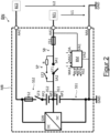
- the vehicle electrical system BN in figure 2 differs from the one in figure 1 illustrated vehicle electrical system in that the first fuse FS1 and the first switch ST1 and the current path SP with the protective resistor R and the second switch ST2 are not between the first battery cell group ZG1 and the ground current connection MA, but between the first output current connection AA1 on the one hand and the first and the second battery cell group ZG1, ZG2 on the other hand electrically connected are.
- the first fuse FS1, the first switch ST1 and the current path SP with the protective resistor R and the second switch ST2 are electrically connected in a common circuit section SB of the first and the second series circuit SS1, SS2, which connects the first output current connection AA1 to the first and the second battery cell group ZG1, ZG2 electrically connects.
- the first switch ST1 is electrically connected via its two connections SA1, SA2 in the common circuit section SB.
- the current path SP with the protective resistor R and the second switch ST2 is then electrically connected between the two terminals SA1, SA2 of the first switch ST1 and in parallel with the first switch ST1.
Landscapes
- Engineering & Computer Science (AREA)
- Power Engineering (AREA)
- Mechanical Engineering (AREA)
- Transportation (AREA)
- Sustainable Energy (AREA)
- Sustainable Development (AREA)
- Life Sciences & Earth Sciences (AREA)
- Manufacturing & Machinery (AREA)
- General Chemical & Material Sciences (AREA)
- Electrochemistry (AREA)
- Chemical Kinetics & Catalysis (AREA)
- Chemical & Material Sciences (AREA)
- Microelectronics & Electronic Packaging (AREA)
- Electric Propulsion And Braking For Vehicles (AREA)
- Charge And Discharge Circuits For Batteries Or The Like (AREA)
Description
Die vorliegende Erfindung betrifft eine Mehrspannungsbatterievorrichtung und ein Bordnetz für ein Kraftfahrzeug, insb. ein Hybridelektro-/Elektrofahrzeug, mit einer Mehrspannungsbatterievorrichtung.The present invention relates to a multi-voltage battery device and an on-board electrical system for a motor vehicle, in particular a hybrid electric/electric vehicle, with a multi-voltage battery device.
Mehrspannungsbatterievorrichtungen zum Bereitstellen von verschiedenen Nenn- bzw. Betriebsspannungen für Bordnetze von Kraftfahrzeugen, insb. Hybridelektro-/Elektrofahrzeugen, sind bekannt.Multi-voltage battery devices for providing different nominal or operating voltages for vehicle electrical systems, especially hybrid electric/electric vehicles, are known.
Durch diverse interne oder externe Einflüsse besteht bei den Bordnetzen die Gefahr überhöhter (Bordnetz-)Ströme, insb. infolge elektrischer Kurzschlüsse in Bordnetzen, wodurch die Mehrspannungsbatterievorrichtungen belastet werden, was wiederum zu Beschädigung in Batteriezellen der Mehrspannungsbatterievorrichtungen führen kann.Due to various internal or external influences, there is a risk of excessive (vehicle electrical system) currents in the vehicle electrical systems, especially as a result of electrical short circuits in vehicle electrical systems, which puts a load on the multi-voltage battery devices, which in turn can lead to damage in the battery cells of the multi-voltage battery devices.
Die Druckschrift
Die Druckschrift
Die Druckschrift
Die Druckschrift
Die Druckschrift
Die Druckschrift
Die Druckschrift
Bei den Mehrspannungsbatterievorrichtungen mit zwei oder mehr Batteriezellengruppen bleibt eine der Batteriezellengruppen auch während eines Ruhemodus, in dem das Fahrzeug (nach Ende eines Fahrbetriebs) abgestellt ist und nur sicherheitsrelevante und sonstige relevante Funktionen des Fahrzeugs durchgeführt werden, mit dem Rest des Bordnetzes elektrisch verbunden, um die relevanten Funktionen weiterhin aufrechterhalten zu können. Damit ist diese Batteriezellengruppe besonders gefährdet durch überhöhte Ströme, insb. elektrische Kurzschlüsse, im Bordnetz. Damit besteht die Aufgabe der Erfindung darin, eine Möglichkeit bereitzustellen, mit der die Mehrspannungsbatterievorrichtungen und somit auch Bordnetze vor Beschädigung durch überhöhte (Bordnetz-)Ströme zuverlässig zu schützen.In the multi-voltage battery devices with two or more battery cell groups, one of the battery cell groups remains electrically connected to the rest of the vehicle electrical system even during a sleep mode in which the vehicle is parked (after the end of driving) and only safety-related and other relevant functions of the vehicle are carried out to be able to continue to maintain the relevant functions. This battery cell group is therefore particularly at risk from excessive currents, especially electrical short circuits, in the vehicle electrical system. The object of the invention is therefore to provide a way of reliably protecting the multi-voltage battery devices and thus also vehicle electrical systems from damage caused by excessive (vehicle electrical system) currents.
Beschreibung der Erfindung:
Diese Aufgabe wird durch den Gegenstand des unabhängigen Anspruchs gelöst. Vorteilhafte Ausgestaltungen sind Gegenstand der Unteransprüche.Description of the invention:
This object is solved by the subject matter of the independent claim. Advantageous configurations are the subject matter of the dependent claims.
Gemäß einem ersten Aspekt der Erfindung wird eine Mehrspannungsbatterievorrichtung für ein Kraftfahrzeug, insb. ein Hybridelektro-/Elektrofahrzeug, bereitgestellt.According to a first aspect of the invention, a multi-voltage battery device for a motor vehicle, in particular a hybrid electric/electric vehicle, is provided.
Die Mehrspannungsbatterievorrichtung umfasst einen ersten Ausgangsstromanschluss und einen Massestromanschluss zum Bereitstellen einer ersten Nennspannung, bspw. einer ersten Bordnetzspannung für ein Bordnetz des Kraftfahrzeugs.The multi-voltage battery device includes a first output power terminal and a ground power terminal for providing a first nominal voltage, for example a first vehicle electrical system voltage for an on-board electrical system of the motor vehicle.
Die Mehrspannungsbatterievorrichtung umfasst ferner einen zweiten Ausgangsstromanschluss, der mit dem Massestromanschluss zum Bereitstellen einer zweiten Nennspannung, bspw. einer zweiten Bordnetzspannung für das Bordnetz, dient.The multi-voltage battery device also includes a second output current connection which, together with the ground current connection, is used to provide a second nominal voltage, for example a second vehicle electrical system voltage for the vehicle electrical system.
Die Mehrspannungsbatterievorrichtung umfasst ferner eine erste Serienschaltung von einer ersten Batteriezellengruppe und einem ersten steuerbaren Schalter, die zwischen dem ersten Ausgangsstromanschluss und dem Massestromanschluss elektrisch angeschlossen ist. Dabei ist der erste Schalter über dessen zwei Anschlüsse in der ersten Serienschaltung elektrisch angeschlossen.The multi-voltage battery device further includes a first series circuit of a first battery cell group and a first controllable switch electrically connected between the first output power terminal and the ground power terminal. In this case, the first switch is electrically connected via its two terminals in the first series circuit.
Die Mehrspannungsbatterievorrichtung umfasst ferner einen Schutzwiderstand, der zwischen den beiden Anschlüssen des ersten Schalters und somit parallel zu dem ersten Schalter elektrisch angeschlossen ist. Der erste Schalter ist eingerichtet, in einem geschlossenen Schaltzustand dessen beiden Anschlüsse miteinander elektrisch kurzzuschließen und somit den Schutzwiderstand zu überbrücken.The multi-voltage battery device further includes a protective resistor electrically connected between the two terminals of the first switch and thus in parallel with the first switch. The first switch is set up, in a closed switching state, to electrically short-circuit its two terminals with one another and thus to bridge the protective resistor.
Die Mehrspannungsbatterievorrichtung umfasst zudem eine zweite Batteriezellengruppe, die zwischen dem zweiten Ausgangsstromanschluss und dem ersten Ausgangsstromanschluss elektrisch angeschlossen ist und mit der ersten Batteriezellengruppe schaltbar in Serie angeschlossen ist.The multi-voltage battery device also includes a second battery cell group electrically connected between the second output power terminal and the first output power terminal and switchably connected in series with the first battery cell group.
Die Mehrspannungsbatterievorrichtung umfasst außerdem eine Batteriemanagementanordnung zum Betreiben der Mehrspannungsbatterievorrichtung. Die Batteriemanagementanordnung ist eingerichtet, im Falle eines zu hohen Stromes oder eines elektrischen Kurzschlusses zwischen dem ersten Ausgangsstromanschluss und dem Massestromanschluss zum Schutz der ersten Batteriezellengruppe und somit der Mehrspannungsbatterievorrichtung vor einer Überlastung durch einen zu hohen Entladestrom den ersten Schalter in einen offenen Schaltzustand zu schalten.The multi-voltage battery device also includes a battery management arrangement for operating the multi-voltage battery device. The battery management arrangement is set up in the event of an excessive current or an electrical short circuit between the first output current connection and to switch the first switch to an open switching state at the ground current connection in order to protect the first battery cell group and thus the multi-voltage battery device from overloading due to an excessively high discharge current.
Um die (erste) Batteriezellengruppe und somit auch die Mehrspannungsbatterievorrichtung vor Störungen durch überhöhte Ströme bzw. elektrische Kurzschlüsse im Bordnetz zu schützen, wurde die Mehrspannungsbatterievorrichtung im Rahmen der Erfindung wie zuvor beschrieben weiterentwickelt.In order to protect the (first) battery cell group and thus also the multi-voltage battery device from faults caused by excessive currents or electrical short circuits in the vehicle electrical system, the multi-voltage battery device was further developed as part of the invention as described above.
Dabei ist der erste Schalter vorgesehen, der die (erste) Batteriezellengruppe wählweise (in einem geschlossenen Schaltzustand) direkt oder (in dem offenen Schaltzustand) über einen Schutzwiderstand mit dem Rest des Bordnetzes elektrisch verbindet. Der Schutzwiderstand dient als Überstromschutz und begrenzt den Entladestrom der (ersten) Batteriezellengruppe bei einem überhöhten Strom oder einem elektrischen Kurzschluss im Bordnetz.The first switch is provided, which electrically connects the (first) battery cell group either directly (in a closed switching state) or (in the open switching state) via a protective resistor to the rest of the vehicle electrical system. The protective resistor serves as overcurrent protection and limits the discharge current of the (first) battery cell group in the event of excessive current or an electrical short circuit in the vehicle electrical system.
Die Steuerung des ersten Schalters erfolgt dabei von einer Batteriemanagementanordnung, die im Falle eines überhöhten Stromes oder eines elektrischen Kurzschlusses im Bordnetz den ersten Schalter in den offenen Schaltzustand schaltet und somit die (erste) Batteriezellengruppe über den Schutzwiderstand mit dem Bordnetz elektrisch verbindet. Als Überstromschutz begrenzt der Schutzwiderstand dann den Entladestrom der (ersten) Batteriezellengruppe und schützt somit diese vor einer Überlastung durch einen überhöhten Entladestrom.The first switch is controlled by a battery management arrangement which, in the event of an excessive current or an electrical short circuit in the vehicle electrical system, switches the first switch to the open switching state and thus electrically connects the (first) battery cell group to the vehicle electrical system via the protective resistor. As overcurrent protection, the protective resistor then limits the discharge current of the (first) battery cell group and thus protects it from overloading due to an excessive discharge current.
Der überhöhte Strom oder der elektrischen Kurzschluss kann bspw. von einer allgemein bekannten, am Bordnetz angeschlossenen Strommesseinheit, wie z. B. einem Hallsensor, erfasst werden, die mit der Batteriemanagementanordnung signaltechnisch in Verbindung steht und bei Vorliegen eines überhöhten Stromes oder eines elektrischen Kurzschlusses ein entsprechendes Datensignal an die Batteriemanagementanordnung abgibt.The excessive current or the electrical short circuit can, for example. B. a Hall sensor, are detected, the signals with the battery management arrangement in connection stands and in the presence of an excessive current or an electrical short circuit emits a corresponding data signal to the battery management arrangement.
Im Falle, dass im Bordnetz kein überhöhter Strom fließt und somit auch kein elektrischer Kurzschluss vorliegt, schaltet die Batteriemanagementanordnung den ersten Schalter in den geschlossenen Schaltzustand und überbrückt somit den Schutzwiderstand. Dadurch wird unnötiger Leistungsverlust durch den Schutzwiderstand vermieden.In the event that no excessive current flows in the vehicle electrical system and there is therefore no electrical short circuit, the battery management arrangement switches the first switch to the closed switching state and thus bypasses the protective resistor. This avoids unnecessary power loss through the protective resistor.
Die Mehrspannungsbatterievorrichtung umfasst ferner einen zweiten Schalter, der zwischen den beiden Anschlüssen des ersten Schalters und in Serie zu dem Schutzwiderstand elektrisch angeschlossen ist. Dabei ist die Batteriemanagementanordnung bspw. ferner eingerichtet, im Falle des überhöhten Stromes oder des elektrischen Kurzschlusses zwischen dem ersten Ausgangsstromanschluss und dem Massestromanschluss den zweiten Schalter in einen geschlossenen Schaltzustand zu schalten und somit einen begrenzten Stromfluss über den Schutzwiderstand zu ermöglichen.The multi-voltage battery device further includes a second switch electrically connected between the two terminals of the first switch and in series with the protective resistor. In this case, the battery management arrangement is, for example, also set up to switch the second switch to a closed switching state in the event of excessive current or an electrical short circuit between the first output current connection and the ground current connection, thus enabling a limited flow of current via the protective resistor.
Die Batteriemanagementanordnung ist ferner eingerichtet, im Falle, dass das Kraftfahrzeug in einem Ruhemodus befindet, den ersten Schalter in den offenen Schaltzustand zu schalten, und somit den Entladestrom der ersten Batteriezellengruppe über den Schutzwiderstand zu begrenzen. Dadurch wird die erste Batteriezellengruppe vor einer möglichen Überlastung durch einen zu hohen Entladestrom geschützt. Ist der zuvor beschriebene zweite Schalter vorhanden, so ist die Batteriemanagementanordnung ferner eingerichtet, den zweiten Schalter in den geschlossenen Schaltzustand zu schalten und somit den begrenzten Stromfluss über den Schutzwiderstand zu ermöglichen.The battery management arrangement is also set up, in the event that the motor vehicle is in a sleep mode, to switch the first switch to the open switching state and thus to limit the discharge current of the first battery cell group via the protective resistor. As a result, the first battery cell group is protected against a possible overload due to a discharge current that is too high. If the second switch described above is present, the battery management arrangement is also set up to switch the second switch to the closed switching state and thus enable the limited flow of current via the protective resistor.
Ein Ruhemodus des Kraftfahrzeugs ist ein Zustand, bei dem das Kraftfahrzeug sich nicht im Fahrbetrieb oder in einem sonstigen aktiven Betrieb befindet. Das Kraftfahrzeug wechselt in den Ruhemodus, wenn bspw. der Fahrzeugantrieb abgeschaltet und der Zündschlüssel aus dem Zündschloss gezogen wird. In diesem Ruhemodus werden in der Regel nur sicherheitsrelevante und sonstige vergleichbare Funktionen weiter aufrechtzuerhalten, was nur eine minimale Stromversorgung beansprucht.A sleep mode of the motor vehicle is a state in which the motor vehicle is not in driving operation or in any other active operation. The motor vehicle switches to sleep mode when, for example, the vehicle drive is switched off and the ignition key is removed from the ignition lock. In this sleep mode, only safety-related and other comparable functions are usually maintained, which only requires a minimal power supply.
Damit ist eine Möglichkeit bereitgestellt, mit der eine Mehrspannungsbatterievorrichtung und somit auch ein Bordnetz vor Beschädigung durch überhöhte (Bordnetz-)Ströme zuverlässig geschützt werden können.A possibility is thus provided with which a multi-voltage battery device and thus also an on-board network can be reliably protected from damage by excessive (on-board network) currents.
Bspw. ist die Batteriemanagementanordnung ferner eingerichtet, im Falle einer internen Störung oder eines internen elektrischen Kurzschlusses in der ersten Batteriezellengruppe den ersten und den zweiten Schalter in den offenen Schaltzustand zu schalten. In diesem offenen Schaltzustand trennen der erste und der zweite Schalter die erste Batteriezellengruppe vom Rest des Bordnetzes elektrisch. Folglich wird das Bordnetz vor einer möglichen Beschädigung durch einen elektrischen Kurzschluss in der ersten Batteriezellengruppe geschützt.For example, the battery management arrangement is also set up to switch the first and the second switch to the open switching state in the event of an internal fault or an internal electrical short circuit in the first battery cell group. In this open switching state, the first and the second switch electrically separate the first battery cell group from the rest of the vehicle electrical system. Consequently, the vehicle electrical system is protected from possible damage caused by an electrical short circuit in the first battery cell group.
Bspw. ist die Batteriemanagementanordnung ferner eingerichtet, bei einem kritischen Ladezustand der ersten Batteriezellengruppe den ersten und den zweiten Schalter in den offenen Schaltzustand zu schalten. Dadurch wird der Stromfluss von der ersten Batteriezellengruppe zu dem Rest des Bordnetzes unterbrochen und die erste Batteriezellengruppe vor einer Tiefentladung geschützt. Bspw. ist die Batteriemanagementanordnung über Versorgungsstromanschlüsse zwischen dem ersten Ausgangsstromanschluss und dem Massestromanschluss, und somit parallel zur ersten Serienschaltung elektrisch angeschlossen. Über diese Versorgungsstromanschlüsse wird die Batteriemanagementanordnung mit Strom versorgt.For example, the battery management arrangement is also set up to switch the first and the second switch to the open switching state when the charge state of the first battery cell group is critical. This interrupts the flow of current from the first battery cell group to the rest of the vehicle electrical system and protects the first battery cell group from deep discharge. For example, the battery management arrangement is via supply current connections between the first output current connection and the ground current connection, and is therefore parallel to the first series circuit electrically connected. The battery management arrangement is supplied with power via these power supply connections.
Bspw. ist der Schutzwiderstand als ein PTC-Widerstand (Kaltleiter, auf Englisch "Positive Temperature Coefficient Thermistor") ausgebildet.For example, the protective resistor is in the form of a PTC resistor (positive temperature coefficient thermistor).
Bspw. umfasst die Mehrspannungsbatterievorrichtung ferner einen uni- oder bidirektionalen Gleichspannungswandler, der eingangsspannungsseitig zwischen dem ersten Ausgangsstromanschluss und der ersten Batteriezellengruppe und ausgangsspannungsseitig zwischen dem zweiten Ausgangsstromanschluss und der zweiten Batteriezellengruppe elektrisch angeschlossen ist. Der Gleichspannungswandler ist eingerichtet, je nach Bedarf bzw. je nach Ladezuständen der beiden Batteriezellengruppen, mit Strom der ersten Batteriezellengruppe die zweite Batteriezellengruppe und/oder mit Strom der zweiten Batteriezellengruppe die erste Batteriezellengruppe aufzuladen. Die Batteriemanagementanordnung ist bspw. ferner eingerichtet, (bei Bedarf) den Gleichspannungswandler zum Aufladen der ersten Batteriezellengruppe mit dem Strom der zweiten Batteriezellengruppe und/oder zum Aufladen der zweiten Batteriezellengruppe mit dem Strom der ersten Batteriezellengruppe zu betreiben.For example, the multi-voltage battery device further includes a unidirectional or bidirectional DC-DC converter electrically connected between the first output power terminal and the first battery cell group on the input side and between the second output power terminal and the second battery cell group on the output side. The DC-DC converter is set up to charge the second battery cell group with current from the first battery cell group and/or to charge the first battery cell group with current from the second battery cell group as required or depending on the state of charge of the two battery cell groups. The battery management arrangement is, for example, also set up (if necessary) to operate the DC-DC converter to charge the first battery cell group with the current from the second battery cell group and/or to charge the second battery cell group with the current from the first battery cell group.
Bspw. umfasst die Mehrspannungsbatterievorrichtung ferner eine zweite Serienschaltung von einem dritten, steuerbaren Schalter und der zweiten Batteriezellengruppe, die zwischen dem zweiten Ausgangsstromanschluss und dem ersten Ausgangsstromanschluss elektrisch angeschlossen ist. Dabei verbindet der dritte Schalter die zweite Batteriezellengruppe mit der ersten Batteriezellengruppe schaltbar elektrisch.For example, the multi-voltage battery device further comprises a second series connection of a third, controllable switch and the second battery cell group, which is electrically connected between the second output current connection and the first output current connection. In this case, the third switch electrically connects the second battery cell group to the first battery cell group in a switchable manner.
Bspw. weisen die erste und die zweite Serienschaltung einen gemeinsamen Schaltungsabschnitt auf, der den ersten Schaltanschluss mit der ersten und der zweiten Batteriezellengruppe elektrisch verbindet. Der erste Schalter bzw. dessen beide Anschlüsse sind dann in diesem gemeinsamen Schaltungsabschnitt elektrisch angeschlossen.For example, the first and second series circuits have a common circuit section that electrically connects the first switching connection to the first and second battery cell groups. The first switch or its two connections are then electrically connected in this common circuit section.
Bspw. sind der zuvor beschriebene erste, zweite und/oder dritte Schalter jeweils als ein Relais ausgebildet.For example, the first, second and/or third switch described above are each designed as a relay.
Der kritische Ladezustand der ersten und/oder der zweiten Batteriezellengruppe liegt bspw. bei unter 30%, 20%, 15%, 10%, 8%, 5% oder 3%. Dabei hängt der kritische Ladezustand unter andrem insb. von verwendeten Materialien bzw. Zellenchemie sowie von Zellentemperaturen und sonstige physikalischen Zuständen der Batteriezellen der ersten bzw. der zweiten Batteriezellengruppe ab.The critical state of charge of the first and/or the second battery cell group is, for example, below 30%, 20%, 15%, 10%, 8%, 5% or 3%. The critical state of charge depends, among other things, in particular on the materials used or cell chemistry as well as cell temperatures and other physical states of the battery cells of the first or second battery cell group.
Bspw. liegen die erste Nennspannung bei 12 Volt und/oder die zweite Nennspannung bei 48 Volt.For example, the first nominal voltage is 12 volts and/or the second nominal voltage is 48 volts.
Gemäß einem weiteren Aspekt der Erfindung wird ein Bordnetz für ein Kraftfahrzeug, insb. ein Hybridelektro-/Elektrofahrzeug, bereitgestellt.According to a further aspect of the invention, an on-board electrical system for a motor vehicle, in particular a hybrid electric/electric vehicle, is provided.
Das Bordnetz umfasst einen ersten Bordnetzzweig mit einer ersten Bordnetzspannung und einen zweiten Bordnetzzweig mit einer zweiten Bordnetzspannung. Das Bordnetz umfasst ferner eine zuvor beschriebene Mehrspannungsbatterievorrichtung, die über den ersten Ausgangsstromanschluss (und den Massestromanschluss) am ersten Bordnetzzweig und über den zweiten Ausgangsstromanschluss (und den Massestromanschluss) am zweiten Bordnetzzweig elektrisch angeschlossen ist.The vehicle electrical system includes a first vehicle electrical system branch with a first vehicle electrical system voltage and a second vehicle electrical system branch with a second vehicle electrical system voltage. The vehicle electrical system also includes a multi-voltage battery device as described above, which is electrically connected to the first vehicle electrical system branch via the first output current connection (and the ground current connection) and to the second vehicle electrical system branch via the second output current connection (and the ground current connection).
Vorteilhafte Ausgestaltungen der oben beschriebenen Mehrspannungsbatterievorrichtung sind, soweit im Übrigen, auf das oben genannte Bordnetz übertragbar, auch als vorteilhafte Ausgestaltungen des Bordnetzes anzusehen.Advantageous refinements of the multi-voltage battery device described above are also to be regarded as advantageous refinements of the vehicle electrical system, insofar as they can otherwise be transferred to the vehicle electrical system mentioned above.
Im Folgenden werden beispielhafte Ausführungsformen der Erfindung Bezug nehmend auf die beiliegenden Zeichnungen näher erläutert. Dabei zeigen:
Figur 1- in einer schematischen Darstellung ein Bordnetz eines Hybridelektrofahrzeugs mit einer Mehrspannungsbatterievorrichtung gemäß einer beispielhaften Ausführungsform der Erfindung; und
- Figur 2
- in einer weiteren schematischen Darstellung ein weiteres Bordnetz eines Hybridelektrofahrzeugs mit einer weiteren Mehrspannungsbatterievorrichtung gemäß einer weiteren beispielhaften Ausführungsform der Erfindung.
- figure 1
- in a schematic representation, an on-board network of a hybrid electric vehicle with a multi-voltage battery device according to an exemplary embodiment of the invention; and
- figure 2
- in a further schematic representation, a further vehicle electrical system of a hybrid electric vehicle with a further multi-voltage battery device according to a further exemplary embodiment of the invention.
Das Bordnetz BN in
Das Bordnetz BN umfasst außerdem eine Mehrspannungsbatterievorrichtung MB zum Bereitstellen bzw. zum Aufrechterhalten der beiden Bordnetzspannungen U1, U2.The vehicle electrical system BN also includes a multi-voltage battery device MB for providing or maintaining the two vehicle electrical system voltages U1, U2.
Die Mehrspannungsbatterievorrichtung MB wird als eine so genannte AES Batterie, also eine 48 Volt Batterie mit einem 12 Volt Abgriff und einem Gleichspannungswandler GW gebaut.The multi-voltage battery device MB is built as a so-called AES battery, ie a 48 volt battery with a 12 volt tap and a DC voltage converter GW.
Die Mehrspannungsbatterievorrichtung MB umfasst stromausgangsseitig einen ersten Ausgangsstromanschluss AA1 und einen Massestromanschluss MA, über die die Mehrspannungsbatterievorrichtung MB an dem ersten Bordnetzzweig BZ1 elektrisch angeschlossen ist. Die Mehrspannungsbatterievorrichtung MB stellt als eine erste Nennspannung (bzw. Nennausgangsspannung) die erste Bordnetzspannung U1, die zwischen dem ersten Ausgangsstromanschluss AA1 und dem Massestromanschluss MA anliegt.On the current output side, the multi-voltage battery device MB comprises a first output current connection AA1 and a ground current connection MA, via which the multi-voltage battery device MB is electrically connected to the first vehicle electrical system branch BZ1. As a first nominal voltage (or nominal output voltage), the multi-voltage battery device MB provides the first vehicle electrical system voltage U1, which is present between the first output current connection AA1 and the ground current connection MA.
Die Mehrspannungsbatterievorrichtung MB umfasst stromausgangsseitig ferner einen zweiten Ausgangsstromanschluss AA2 und ist über den zweiten Ausgangsstromanschluss AA2 und den Massestromanschluss MA an dem zweiten Bordnetzzweig BZ2 elektrisch angeschlossen. Die Mehrspannungsbatterievorrichtung MB stellt als eine zweite Nennspannung (bzw. Nennausgangsspannung) die zweite Bordnetzspannung U2, die zwischen dem zweiten Ausgangsstromanschluss AA2 und dem Massestromanschluss MA anliegt.On the current output side, the multi-voltage battery device MB also includes a second output current connection AA2 and is electrically connected to the second vehicle electrical system branch BZ2 via the second output current connection AA2 and the ground current connection MA. The multi-voltage battery device MB provides the second vehicle electrical system voltage U2, which is present between the second output current connection AA2 and the ground current connection MA, as a second nominal voltage (or nominal output voltage).
Die Mehrspannungsbatterievorrichtung MB umfasst zwischen dem ersten Ausgangsstromanschluss AA1 und dem Massestromanschluss MA eine erste Serienschaltung SS1 von einer ersten Batteriezellengruppe ZG1, einer ersten Schmelzsicherung FS1 sowie einem ersten steuerbaren Schalter ST1, der aus einem entsprechenden allgemein bekannten Relais ausgebildet ist. Die erste Serienschaltung SS1 mit der ersten Batteriezellengruppe ZG1 bildet somit eine erste Strom-/Spannungsquelle für den ersten Bordnetzzweig BZ1. Die erste Batteriezellengruppe ZG1 weist eine Nennspannung in Höhe von 12 Volt auf und stellt somit die erste Bordnetzspannung U1 bereit. Dabei ist die erste Batteriezellengruppe ZG1 über ihren Pluspol PP1 mit dem ersten Ausgangsstromanschluss AA1 und über ihren Minuspol NP1 (und weiter über die erste Schmelzsicherung FS1 und den ersten Schalter ST1) mit dem Massestromanschluss MA elektrisch verbunden. Der erste Schalter ST1 weist zwei Anschlüsse SA1, SA2 auf, die in der ersten Serienschaltung SS1 seriell elektrisch angeschlossen sind.Between the first output current connection AA1 and the ground current connection MA, the multi-voltage battery device MB comprises a first series circuit SS1 of a first battery cell group ZG1, a first safety fuse FS1 and a first controllable switch ST1, which is formed from a corresponding, well-known relay. The first series circuit SS1 with the first battery cell group ZG1 thus forms a first current/voltage source for the first vehicle electrical system branch BZ1. The first battery cell group ZG1 has a nominal voltage of 12 volts and thus provides the first vehicle electrical system voltage U1. The first battery cell group ZG1 is electrically connected to the first output current connection AA1 via its positive pole PP1 and to the ground current connection MA via its negative pole NP1 (and further via the first safety fuse FS1 and the first switch ST1). The first switch ST1 has two connections SA1, SA2, which are electrically connected in series in the first series circuit SS1.
Die Mehrspannungsbatterievorrichtung MB umfasst ferner einen Strompfad SP zwischen den beiden Anschlüssen SA1, SA2 des ersten Schalters ST1, der sich somit parallel zu dem Schalter ST1 erstreckt. Der Strompfad SP umfasst einen Schutzwiderstand R und einen zweiten steuerbaren Schalter ST2, die zueinander in Serie elektrisch angeschlossen sind. Dabei ist der Schutzwiderstand R als ein PTC-Widerstand ausgebildet. Der zweite Schalter ST2 ist wie der erste Schalter ST1 aus einem entsprechenden allgemein bekannten Relais ausgebildet. In einem geschlossen Schaltzustand ermöglicht der zweite Schalter ST2 einen Stromfluss durch den Strompfad SP und über den Schutzwiderstand R. In einem offenen Schaltzustand unterbricht der zweite Schalter ST2 den Stromfluss durch den Strompfad SP.The multi-voltage battery device MB also includes a current path SP between the two terminals SA1, SA2 of the first switch ST1, which thus extends parallel to the switch ST1. The current path SP includes a protective resistor R and a second controllable switch ST2, which are electrically connected to one another in series. In this case, the protective resistor R is designed as a PTC resistor. Like the first switch ST1, the second switch ST2 is formed from a corresponding, generally known relay. In a closed switching state, the second switch ST2 allows current to flow through the current path SP and via the protective resistor R. In an open switching state, the second switch ST2 interrupts the current flow through the current path SP.
In einem geschlossenen Schaltzustand schließt der erste Schalter ST1 seine beiden Anschlüsse SA1, SA2 miteinander elektrisch kurz und überbrückt somit den Strompfad SP mit dem Schutzwiderstand R. In einem offenen Schaltzustand unterbricht der erste Schalter ST1 den direkten Stromfluss zwischen den beiden Anschlüssen SA1, SA2 und ermöglicht somit einen Stromfluss über den Strompfad SP und somit über den Schutzwiderstand R.In a closed switching state, the first switch ST1 electrically short-circuits its two connections SA1, SA2 with one another and thus bridges the current path SP with the protective resistor R. In an open switching state, the first switch ST1 interrupts the direct flow of current between the two connections SA1, SA2 and enables it thus a current flow via the current path SP and thus via the protective resistor R.
Die Mehrspannungsbatterievorrichtung MB umfasst zwischen dem ersten Ausgangsstromanschluss AA1 und dem zweiten Ausgangsstromanschluss AA2 eine zweite Serienschaltung SS2 von einer zweiten Schmelzsicherung FS2, einer zweiten Batteriezellengruppe ZG2, sowie einem dritten steuerbaren Schalter ST3, der wie die beiden vorgenannten Schalter ST1, ST2 aus einem entsprechenden allgemein bekannten Relais ausgebildet ist. Dabei ist die zweite Batteriezellengruppe ZG2 über ihren Pluspol PP2 (und weiter über den Schalter ST und die zweite Schmelzsicherung FS2) mit dem zweiten Ausgangsstromanschluss AA2 und über ihren Minuspol NP2 mit dem ersten Ausgangsstromanschluss AA1 elektrisch verbunden.The multi-voltage battery device MB includes between the first output power terminal AA1 and the second output power terminal AA2 a second series circuit SS2 of a second safety fuse FS2, a second battery cell group ZG2, and a third controllable switch ST3, which, like the two aforementioned switches ST1, ST2, is formed from a corresponding, well-known relay. The second battery cell group ZG2 is electrically connected to the second output current connection AA2 via its positive pole PP2 (and further via the switch ST and the second safety fuse FS2) and to the first output current connection AA1 via its negative pole NP2.
Zwischen dem zweiten Ausgangsstromanschluss AA2 und dem Massestromanschluss MA bilden die erste und die zweite Serienschaltungen SS1, SS2 somit eine größere Serienschaltung von den beiden Batteriezellengruppen ZG1, ZG2, den beiden Schmelzsicherungen FS1, FS2 sowie den ersten und den dritten Schalter ST1, ST3, wobei die beiden Batteriezellengruppen ZG1, ZG2 über den dritten Schalter ST3 zueinander schaltbar in Serie geschaltet sind.Between the second output current connection AA2 and the ground current connection MA, the first and the second series connections SS1, SS2 thus form a larger series connection of the two battery cell groups ZG1, ZG2, the two safety fuses FS1, FS2 and the first and the third switch ST1, ST3, the the two battery cell groups ZG1, ZG2 are connected in series so that they can be switched to one another via the third switch ST3.
Die zweite Serienschaltung SS2 mit der zweiten Batteriezellengruppe ZG2 bildet mit der ersten Serienschaltung samt der ersten Batteriezellengruppe ZG1 in Serie eine zweite Strom-/Spannungsquelle für den zweiten Bordnetzzweig BZ2. Die zweite Batteriezellengruppe ZG2 weist dabei eine Nennspannung in Höhe von 36 Volt auf und stellt mit der in Serie geschalteten ersten Batteriezellengruppe ZG1 mit der Nennspannung von 12 Volt die zweite Bordnetzspannung U2 von 48 Volt bereit.The second series circuit SS2 with the second battery cell group ZG2 forms a second current/voltage source for the second vehicle electrical system branch BZ2 with the first series circuit together with the first battery cell group ZG1 in series. The second battery cell group ZG2 has a nominal voltage of 36 volts and, together with the series-connected first battery cell group ZG1 with the nominal voltage of 12 volts, provides the second vehicle electrical system voltage U2 of 48 volts.
Dabei sind die beiden Batteriezellengruppen ZG1, ZG2 aus Li-Ionen Zellen ausgebaut.The two battery cell groups ZG1, ZG2 are made from Li-ion cells.
Die Mehrspannungsbatterievorrichtung MB umfasst außerdem einen bidirektionalen Gleichspannungswandler GW, der eingangsspannungsseitig zwischen dem ersten Ausgangsstromanschluss AA1 und der ersten Batteriezellengruppe ZG1, sowie ausgangsspannungsseitig zwischen dem zweiten Ausgangsstromanschluss AA2 und der zweiten Batteriezellengruppe ZG2 elektrisch angeschlossen ist. Der Gleichspannungswandler GW ist eingerichtet, bei Bedarf die zweite Batteriezellengruppe ZG2 mit Strom der ersten Batteriezellengruppe ZG1 und/oder die erste Batteriezellengruppe ZG1 mit Strom der zweiten Batteriezellengruppe ZG2 aufzuladen.The multi-voltage battery device MB also includes a bidirectional DC-DC converter GW, which is on the input voltage side is electrically connected between the first output current connection AA1 and the first battery cell group ZG1, and on the output voltage side between the second output current connection AA2 and the second battery cell group ZG2. The DC-DC converter GW is set up, if required, to charge the second battery cell group ZG2 with current from the first battery cell group ZG1 and/or the first battery cell group ZG1 with current from the second battery cell group ZG2.
Die Mehrspannungsbatterievorrichtung MB umfasst zudem eine Batteriemanagementanordnung BM zum Betreiben bzw. zum Steuern oder zum Regeln der Mehrspannungsbatterievorrichtung MB. Die Batteriemanagementanordnung BM ist über ihre Versorgungsstromanschlüsse VA1, VA2 zwischen dem ersten Ausgangsstromanschluss AA1 und dem Massestromanschluss MA und somit parallel zur ersten Serienschaltung SS1 elektrisch angeschlossen. Damit wird die Batteriemanagementanordnung BM von der ersten Batteriezellengruppe ZG1 mit Strom versorgt (sofern sich der erste und der zweite Schalter ST1, ST2 in dem geschlossenen Schaltzustand befinden).The multi-voltage battery device MB also includes a battery management arrangement BM for operating or for controlling or for regulating the multi-voltage battery device MB. The battery management arrangement BM is electrically connected via its supply current connections VA1, VA2 between the first output current connection AA1 and the ground current connection MA and thus in parallel with the first series circuit SS1. The battery management arrangement BM is thus supplied with power from the first battery cell group ZG1 (if the first and the second switch ST1, ST2 are in the closed switching state).
Die Batteriemanagementanordnung BM ist signaleingangsseitig über zwei Messsignalanschlüsse MA1, MA2 mit den beiden Batteriezellengruppen ZG1, ZG2 messtechnisch verbunden und überwacht über diese Messsignalanschlüsse MA1, MA2 in einer dem Fachmann bekannten Weise Zellenspannungen, Ladezustände (auf Englisch "State of Charge, SoC"), Alterungszustände (auf Englisch "State of Health, SoH") und sonstige Eigenschaften, wie z. B. Zellentemperaturen, der beiden Batteriezellengruppen ZG1, ZG2. Ferner ist die Batteriemanagementanordnung BM signaleingangsseitig über einen Datensignalanschluss DA mit einer externen Strommesseinheit im ersten Bordnetzzweig BZ1 signaltechnisch verbunden. Die Strommesseinheit erfasst in einer dem Fachmann bekannten Weise überhöhte Bordnetzströme bzw. elektrische Kurzschlüsse im ersten Bordnetzzweig BZ1 und gibt der Batteriemanagementanordnung BM Informationen über überhöhte Bordnetzströme bzw. elektrische Kurzschlüsse im ersten Bordnetzzweig BZ1 ab.On the signal input side, the battery management arrangement BM is connected to the two battery cell groups ZG1, ZG2 via two measurement signal connections MA1, MA2 and monitors cell voltages, states of charge (in English "State of Charge, SoC"), and aging states via these measurement signal connections MA1, MA2 in a manner known to those skilled in the art (in English "State of Health, SoH") and other characteristics, such as e.g. B. cell temperatures, the two battery cell groups ZG1, ZG2. Furthermore, the battery management arrangement BM is connected on the signal input side via a data signal connection DA to an external current measuring unit in the first vehicle electrical system branch BZ1. The current measuring unit records in a manner known to those skilled in the art, excessive vehicle electrical system currents or electrical short circuits in the first vehicle electrical system branch BZ1 and provides the battery management arrangement BM with information about excessive vehicle electrical system currents or electrical short circuits in the first vehicle electrical system branch BZ1.
Signalausgangsseitig ist die Batteriemanagementanordnung BM über vier Steuersignalanschlüsse AS1, AS2, AS3, AS4 mit dem Gleichspannungswandler GW und den drei Schaltern ST1, ST2, ST3 bzw. mit jeweiligen Steuersignalanschlüssen dieser vier Schaltungskomponenten signaltechnisch verbunden und steuert bzw. regelt diese Schaltungskomponenten.On the signal output side, the battery management arrangement BM is connected via four control signal connections AS1, AS2, AS3, AS4 to the DC/DC converter GW and the three switches ST1, ST2, ST3 or to the respective control signal connections of these four circuit components and controls or regulates these circuit components.
Die Batteriemanagementanordnung BM ist eingerichtet, in einer dem Fachmann bekannten Weise Ladezustände der beiden Batteriezellengruppen ZG1, ZG2 zu überwachen und bei kritischen Ladezuständen der jeweiligen Batteriezellengruppen ZG1, ZG2 den Gleichspannungswandler GW und die drei Schalter ST1, ST2, ST3 derart zu steuern oder zu regeln, sodass die beiden Batteriezellengruppen ZG1, ZG2 jeweils mit dem Strom von der jeweils anderen Batteriezellengruppe ZG1, ZG2 aufgeladen werden und somit vor Beschädigungen durch Tiefentladung geschützt werden.The battery management arrangement BM is set up, in a manner known to those skilled in the art, to monitor the state of charge of the two battery cell groups ZG1, ZG2 and, in the event of critical states of charge of the respective battery cell groups ZG1, ZG2, to control or regulate the DC-DC converter GW and the three switches ST1, ST2, ST3 in such a way so that the two battery cell groups ZG1, ZG2 are each charged with the current from the other battery cell group ZG1, ZG2 and are thus protected from damage due to deep discharge.
Die Batteriemanagementanordnung BM ist ferner eingerichtet, im Falle, dass diese von der Strommesseinheit über einen überhöhten Bordnetzstrom bzw. einen elektrischen Kurzschluss im ersten Bordnetzzweig BZ1 erfährt, den ersten Schalter ST1 in den offenen Schaltzustand zu schalten und zugleich den zweiten Schalter ST2 in den geschlossenen Schaltzustand zu schalten, wodurch die Stromverbindung zwischen der ersten Batteriezellengruppe ZG1 und dem ersten Bordnetzzweig BZ1 durch den Schutzwiderstand R verläuft. Der Schutzwiderstand R begrenzt den Entladestrom der ersten Batteriezellengruppe ZG1 und schützt somit die erste Batteriezellengruppe ZG1 vor einer Überlastung. Dabei steigt der Widerstandswert des (als PTC-Widerstand ausgebildeten) Schutzwiderstands R mit dem steigenden Stromwert des durch die erste Serienschaltung SS1 fließenden Entladestromes infolge der mit dem steigenden Stromwert aufsteigenden Temperatur am Schutzwiderstand R. Dadurch steigt auch die strombegrenzende Wirkung des Schutzwiderstands R mit dem steigenden Stromwert des Entladestromes.The battery management system BM is also set up to switch the first switch ST1 to the open switching state and at the same time to switch the second switch ST2 to the closed switching state if it learns from the current measuring unit about an excessive vehicle electrical system current or an electrical short circuit in the first vehicle electrical system branch BZ1 to switch, whereby the current connection between the first battery cell group ZG1 and the first vehicle electrical system branch BZ1 runs through the protective resistor R. The protective resistor R limits the discharge current of the first battery cell group ZG1 and thus protects the first battery cell group ZG1 from overloading. At the same time, it rises Resistance value of the protective resistor R (designed as a PTC resistor) with the increasing current value of the discharge current flowing through the first series circuit SS1 as a result of the rising temperature at the protective resistor R with the increasing current value. As a result, the current-limiting effect of the protective resistor R also increases with the increasing current value of the discharge current .
Darüber hinaus überwacht die Batteriemanagementanordnung BM anhand von gemessenen Zellenspannungen und/oder Zellentemperaturen interne Störungen, wie z. B. interne elektrische Kurzschlüsse, bei den Batteriezellen der ersten Batteriezellengruppe ZG1. Beim Vorliegen einer internen Störung schaltet die Batteriemanagementanordnung BM den ersten und den zweiten Schalter ST1, ST2 in den offenen Schaltzustand. Dadurch wird die elektrische Verbindung zwischen der ersten Batteriezellengruppe ZG1 und dem ersten Bordnetzzweig BZ1 unterbrochen.In addition, the battery management arrangement BM uses measured cell voltages and/or cell temperatures to monitor internal faults, such as e.g. B. internal electrical short circuits in the battery cells of the first battery cell group ZG1. If an internal fault is present, the battery management arrangement BM switches the first and the second switch ST1, ST2 to the open switching state. As a result, the electrical connection between the first battery cell group ZG1 and the first vehicle electrical system branch BZ1 is interrupted.
Wird das Kraftfahrzeug nach Ende eines Fahrbetriebs abgestellt und geht in ein Ruhemodus, so werden nur sicherheitsrelevante und sonstige relevante Funktionen des Fahrzeugs weiterhin durchgeführt. Entsprechend verbrauchen elektrische Systeme bzw. Komponenten, wie z. B. Sensoren, Bussysteme und Steuergeräte, die diese relevanten Funktionen durchführen, weiterhin Strom.If the motor vehicle is switched off after the end of a driving operation and goes into a sleep mode, then only safety-related and other relevant functions of the vehicle continue to be carried out. Accordingly consume electrical systems or components such. B. Sensors, bus systems and control units that perform these relevant functions continue to use electricity.
In der Regel weisen diese Systeme bzw. Komponenten eine Nennspannung von 12 Volt (12 Volt Verbraucher) auf und sind daher in dem ersten Bordnetzzweig BZ1 angeschlossen und werden folglich von der ersten Batteriezellengruppe ZG1 - auch während des Ruhemodus des Fahrzeugs - mit Strom versorgt.As a rule, these systems or components have a nominal voltage of 12 volts (12 volt consumers) and are therefore connected to the first vehicle electrical system branch BZ1 and are consequently supplied with power by the first battery cell group ZG1 - even when the vehicle is in the idle mode.
Um die Stromversorgung über eine möglichst lange Zeitdauer aufrechterhalten zu können bzw. eine Tiefentladung bei den Batteriezellen der ersten Batteriezellengruppe ZG1 zu vermeiden, sollte der Stromverbrauch während des Ruhemodus möglichst niedrig gehalten werden.In order to be able to maintain the power supply over as long a period of time as possible or to avoid deep discharge in the battery cells of the first battery cell group ZG1, power consumption should be kept as low as possible during sleep mode.
Hierzu schaltet die Batteriemanagementanordnung BM den ersten Schalter ST1 in den offenen Schaltzustand und zugleich den zweiten Schalter ST2 in den geschlossenen Schaltzustand, und zwar unabhängig davon, ob in dem ersten Bordnetzzweig BZ1 ein überhöhter Bordnetzstrom bzw. ein elektrischer Kurzschluss vorliegt, und schützt somit die erste Batteriezellengruppe ZG1 über die gesamten Dauer des Ruhemodus vorsorglich vor überhöhten Entladeströmen.For this purpose, the battery management arrangement BM switches the first switch ST1 to the open switching state and at the same time the second switch ST2 to the closed switching state, regardless of whether there is an excessive on-board power supply current or an electrical short circuit in the first on-board power supply branch BZ1, and thus protects the first Battery cell group ZG1 as a precaution against excessive discharge currents over the entire duration of the sleep mode.
In diesem Fall ist es für die Batteriemanagementanordnung BM nicht mehr erforderlich, währen des Ruhemodus den Stromwert im ersten Bordnetzzweig BZ1 zu überwachen. Dies reduziert den Strombedarf der Batteriemanagementanordnung BM, wodurch wiederum weniger Strom von der ersten Batteriezellengruppe ZG1 abgenommen wird.In this case, it is no longer necessary for the battery management arrangement BM to monitor the current value in the first vehicle electrical system branch BZ1 during the idle mode. This reduces the power requirement of the battery management arrangement BM, which in turn means that less power is drawn from the first battery cell group ZG1.
Der Stromverlust an dem Schutzwiderstand R ist vergleichsweise gering aufgrund des an sich niedrigen Entladestromes der ersten Batteriezellengruppe ZG1 und der Tatsache, dass der Schutzwiderstand R als PTC-Widerstand beim geringen Entladestrom und somit bei einer niedrigen Eigentemperatur einen geringen Widerstandswert aufweist.The power loss at the protective resistor R is comparatively low due to the inherently low discharge current of the first battery cell group ZG1 and the fact that the protective resistor R as a PTC resistor has a low resistance value when the discharge current is low and thus when the intrinsic temperature is low.
Das Bordnetz BN in
Dabei ist der erste Schalter ST1 über dessen beiden Anschlüsse SA1, SA2 in dem gemeinsamen Schaltungsabschnitt SB elektrisch verbunden. Der Strompfad SP mit dem Schutzwiderstand R und dem zweiten Schalter ST2 ist dann zwischen den beiden Anschlüsse SA1, SA2 des ersten Schalters ST1 und parallel zu dem erste Schalter ST1 elektrisch angeschlossen.In this case, the first switch ST1 is electrically connected via its two connections SA1, SA2 in the common circuit section SB. The current path SP with the protective resistor R and the second switch ST2 is then electrically connected between the two terminals SA1, SA2 of the first switch ST1 and in parallel with the first switch ST1.
Claims (9)
- Multi-voltage battery device (MB) for a motor vehicle, comprising:- a first electrical output terminal (AA1) and an electrical earth terminal (MA) for the provision of a first rated voltage (U1);- a second electrical output terminal (AA2) and the electrical earth terminal (MA) for the provision of a second rated voltage (U2);- a first series circuit (SS1) of a first battery cell group (ZG1) and a first controllable switch (ST1) between the first electrical output terminal (AA1) and the electrical earth terminal (MA), wherein the first switch (ST1) is electrically connected into the first series circuit (SS1) via two terminals (SA1, SA2);- a second battery cell group (ZG2), that is electrically connected between the second electrical output terminal (AA2) and the first electrical output terminal (AA1), and is connected switchably in series with the first battery cell group (ZG1);- a battery management assembly (BM) for operating the multi-voltage battery device (MB),wherein the multi-voltage battery device (MB) also has:- a protective resistor (R) that is electrically connected between the two terminals (SA1, SA2) of the first switch (ST1), and thus parallel to the first switch (ST1);- wherein the first switch (ST1) is configured to bridge the protective resistor (R) when in a closed switch state;- wherein the battery management assembly (BM) is configured to switch the first switch (ST1) into an open switch state to protect the first battery cell group (ZG1) in the event of an excessively high current or of an electrical short circuit between the first electrical output terminal (AA1) and the electrical earth terminal (MA);- a second switch (ST2) that is electrically connected between the two terminals (SA1, SA2) of the first switch (ST1), and in series with the protective resistor (R);- wherein the battery management assembly (BM) is further configured to switch the second switch (ST2) into a closed switch state in the event of the excessively high current or of the electrical short circuit between the first electrical output terminal (AA1) and the electrical earth terminal (MA);- wherein the battery management assembly (BM) is further configured to switch the first switch (ST1) into the open switch state and to switch the second switch (ST2) into the closed switch state in the event that the motor vehicle is in an idle mode, that is to say is not in the driving mode or in another active mode.
- Multi-voltage battery device (MB) according to Claim 1, wherein the battery management assembly (BM) is further configured to switch the first (ST1) and the second (ST2) switches into the open switch state in the event of an internal malfunction or an internal electrical short circuit in the first battery cell group (ZG1).
- Multi-voltage battery device (MB) according to one of Claims 1 to 2, wherein the battery management assembly (BM) is further configured to switch the first (ST1) and the second (ST2) switches into the open switch state in the event of a critical charge state of the first battery cell group (ZG1).
- Multi-voltage battery device (MB) according to one of the preceding claims, wherein the battery management assembly (BM) is electrically connected via electrical supply connections (VA1, VA2) between the first electrical output terminal (AA1) and the electrical earth terminal (MA), and parallel to the first series circuit (SS1).
- Multi-voltage battery device (MB) according to one of the preceding claims, wherein the protective resistor (R) is implemented as a PTC resistor.
- Multi-voltage battery device (MB) according to one of the preceding claims, further comprising:- a unidirectional or bidirectional DC voltage converter (GW) that is electrically connected on the input voltage side between the first electrical output terminal (AA1) and the first battery cell group (ZG1) and on the output voltage side between the second electrical output terminal (AA2) and the second battery cell group (ZG2), and which is configured to charge the second battery cell group (ZG2) with current of the first battery cell group (ZG1) and/or the first battery cell group (ZG1) with current of the second battery cell group (ZG2);- wherein the battery management assembly (BM) is further configured to operate the DC voltage converter (GW) to charge the first battery cell group (ZG1) with the current of the second battery cell group (ZG2) and/or to charge the second battery cell group (ZG2) with the current of the first battery cell group (ZG1).
- Multi-voltage battery device (MB) according to one of the preceding claims, further comprising:- a second series circuit (SS2) consisting of a third controllable switch (ST3) and the second battery cell group (ZG2) between the second electrical output terminal (AA2) and the first electrical output terminal (AA1);- wherein the third switch (ST3) connects the second battery cell group (ZG2) to the first battery cell group (ZG1) in an electrically switchable manner.
- Multi-voltage battery device (MB) according to Claim 7,- wherein the first (SS1) and the second (SS2) series circuits comprise a common circuit segment (SB) that electrically connects the first electrical output terminal (AA1) to the first (ZG1) and the second (ZG2) battery cell groups;- wherein the first switch (ST1), or its two terminals (SA1, SA2) are electrically connected into the circuit segment (SB).
- On-board electrical system (BN) for a motor vehicle, comprising:- a first on-board electrical system branch (BZ1) with a first on-board electrical system voltage (U1);- a second on-board electrical system branch (BZ2) with a second on-board electrical system voltage (U2);- a multi-voltage battery device (MB) according to one of the preceding claims, that is electrically connected via the first electrical output terminal (AA1) to the first on-board electrical system branch (BZ1) and via the second electrical output terminal (AA2) to the second on-board electrical system branch (BZ2).
Applications Claiming Priority (2)
| Application Number | Priority Date | Filing Date | Title |
|---|---|---|---|
| DE102018211582.6A DE102018211582B4 (en) | 2018-07-12 | 2018-07-12 | Multi-voltage battery device and vehicle electrical system for a motor vehicle |
| PCT/EP2019/068451 WO2020011806A1 (en) | 2018-07-12 | 2019-07-09 | Multi-voltage battery device and electrical system for a motor vehicle |
Publications (2)
| Publication Number | Publication Date |
|---|---|
| EP3820733A1 EP3820733A1 (en) | 2021-05-19 |
| EP3820733B1 true EP3820733B1 (en) | 2023-09-06 |
Family
ID=67253892
Family Applications (1)
| Application Number | Title | Priority Date | Filing Date |
|---|---|---|---|
| EP19739259.0A Active EP3820733B1 (en) | 2018-07-12 | 2019-07-09 | Multi-voltage battery device and electrical system for a motor vehicle |
Country Status (5)
| Country | Link |
|---|---|
| US (1) | US11932136B2 (en) |
| EP (1) | EP3820733B1 (en) |
| CN (1) | CN112351908B (en) |
| DE (1) | DE102018211582B4 (en) |
| WO (1) | WO2020011806A1 (en) |
Families Citing this family (1)
| Publication number | Priority date | Publication date | Assignee | Title |
|---|---|---|---|---|
| FR3120485B1 (en) * | 2021-03-08 | 2023-07-07 | Valeo Systemes De Controle Moteur | VOLTAGE SUPPLY SYSTEM, METHOD FOR SUPPLYING A LOAD BY SUCH A VOLTAGE SUPPLY SYSTEM AND VEHICLE COMPRISING SUCH A VOLTAGE SUPPLY SYSTEM |
Citations (1)
| Publication number | Priority date | Publication date | Assignee | Title |
|---|---|---|---|---|
| DE102016215559A1 (en) * | 2016-08-19 | 2018-02-22 | Continental Automotive Gmbh | Power supply circuit |
Family Cites Families (15)
| Publication number | Priority date | Publication date | Assignee | Title |
|---|---|---|---|---|
| DE10258894B3 (en) * | 2002-12-17 | 2004-01-29 | Vb Autobatterie Gmbh | Energy supply device for an on-board network of vehicles |
| DE10361743A1 (en) * | 2002-12-30 | 2004-09-09 | Volkswagen Ag | Vehicle battery switching device, for switching between supply voltages, has an arrangement that ensures battery cell groups are connected in parallel during a jump-start procedure |
| KR100740097B1 (en) * | 2005-10-20 | 2007-07-16 | 삼성에스디아이 주식회사 | Method of estimating SOC for battery and battery management system using the same |
| DE102010011276A1 (en) * | 2010-03-13 | 2011-09-15 | Continental Automotive Gmbh | On-board network for a vehicle |
| US10050437B2 (en) | 2011-06-30 | 2018-08-14 | Furukawa Electric Co., Ltd. | Power supply apparatus and power supply method |
| JP5606488B2 (en) | 2012-04-19 | 2014-10-15 | 三菱電機株式会社 | In-vehicle power supply |
| DE102012017674A1 (en) | 2012-09-07 | 2014-03-13 | Audi Ag | Motor vehicle with a multi-voltage electrical system and associated method |
| DE102014214984A1 (en) | 2014-07-30 | 2016-02-04 | Robert Bosch Gmbh | Short-circuit protection device |
| DE102014219504B4 (en) | 2014-09-26 | 2022-12-08 | Vitesco Technologies GmbH | Wireless battery charging system with emergency shutdown for an electric vehicle traction battery |
| DE102015219589A1 (en) | 2015-10-09 | 2017-04-13 | Continental Automotive Gmbh | Vehicle battery device |
| DE102015220223A1 (en) | 2015-10-16 | 2017-04-20 | Zf Friedrichshafen Ag | Limitation of the current gradient during load shedding |
| DE102015223546B4 (en) | 2015-11-27 | 2020-09-10 | Vitesco Technologies Germany Gmbh | Circuit arrangement, vehicle electrical system with a circuit arrangement |
| DE102016207033A1 (en) | 2016-04-26 | 2017-10-26 | Continental Automotive Gmbh | Electrical energy storage device for a vehicle electrical system, vehicle electrical system |
| US10295584B2 (en) * | 2016-09-14 | 2019-05-21 | Johnson Controls Technology Company | Systems and methods for measuring isolation resistance |
| DE102017206809A1 (en) | 2016-12-14 | 2018-01-04 | Continental Automotive Gmbh | DC-DC converter, vehicle electrical system with a DC-DC converter |
-
2018
- 2018-07-12 DE DE102018211582.6A patent/DE102018211582B4/en active Active
-
2019
- 2019-07-09 EP EP19739259.0A patent/EP3820733B1/en active Active
- 2019-07-09 WO PCT/EP2019/068451 patent/WO2020011806A1/en unknown
- 2019-07-09 CN CN201980046692.4A patent/CN112351908B/en active Active
- 2019-07-09 US US17/257,636 patent/US11932136B2/en active Active
Patent Citations (1)
| Publication number | Priority date | Publication date | Assignee | Title |
|---|---|---|---|---|
| DE102016215559A1 (en) * | 2016-08-19 | 2018-02-22 | Continental Automotive Gmbh | Power supply circuit |
Also Published As
| Publication number | Publication date |
|---|---|
| CN112351908A (en) | 2021-02-09 |
| EP3820733A1 (en) | 2021-05-19 |
| US20210268935A1 (en) | 2021-09-02 |
| DE102018211582B4 (en) | 2020-03-05 |
| WO2020011806A1 (en) | 2020-01-16 |
| DE102018211582A1 (en) | 2020-01-16 |
| CN112351908B (en) | 2024-02-13 |
| US11932136B2 (en) | 2024-03-19 |
Similar Documents
| Publication | Publication Date | Title |
|---|---|---|
| EP1411364B1 (en) | Vehicle instrument panel for identifying the state of a battery connected to the positive pole of the battery | |
| EP1561269B1 (en) | On-board power supply network for supplying at least one consumer having high demands in terms of the availability of the on-board power supply network | |
| DE102012222208B4 (en) | Method for the controlled connection of several on-board network branches of a vehicle, control unit for executing the method and on-board network | |
| EP3669432B1 (en) | Shutdown device for an electric supply network | |
| WO2011121035A1 (en) | On-board electrical system for a vehicle and also control apparatus for an on-board electrical system | |
| DE102011083582A1 (en) | Power distributor for electrical system of motor vehicle, has electronic control and regulating unit for driving, controlling and monitoring load control circuits connected between junction points and load current outputs | |
| EP1241768A2 (en) | Method and device for protecting a multi-voltage vehicle network against voltage breakdowns between different voltage surfaces and against polarity reversal from outside | |
| DE102017204065A1 (en) | Drive system for a vehicle and method for operating a drive system | |
| DE102011105971A1 (en) | Board power supply arrangement for motor car, has load branches comprising voltage tap connected with power supply, where electric voltage of power supply is provided with electrical voltage value for supplying another power supply | |
| DE102018105826B4 (en) | ELECTRICAL SUPPLY SYSTEM AND PROCEDURE | |
| EP3820733B1 (en) | Multi-voltage battery device and electrical system for a motor vehicle | |
| WO2019115335A1 (en) | Multi-voltage battery device and onboard electrical system for a motor vehicle | |
| DE102018006582B4 (en) | Battery for a motor vehicle and vehicle electrical system | |
| EP2779354A2 (en) | Electrical intrinsically safe battery module with pole-reversible output voltage, and a method for monitoring a battery module | |
| DE102018210979B4 (en) | Multi-voltage battery device and multi-voltage vehicle electrical system for a motor vehicle | |
| EP3630527A1 (en) | Vehicle energy store | |
| DE102022001414A1 (en) | Jump-start connection for an on-board electrical system of a vehicle with a separate reverse polarity protection device and on-board electrical system with a corresponding jump-start connection | |
| DE102013009991A1 (en) | Externally launchable integration of a battery in a motor vehicle electrical system | |
| DE102017222544A1 (en) | Multi-voltage battery device and electrical system for a motor vehicle | |
| DE102013003586A1 (en) | Electrical power supply system for motor car, has conductor path electrically connecting power supply unit with onboard network, and locking element comprising response time shorter than response time of fuse element | |
| DE102013007704B4 (en) | Battery protection by means of an active current sensor | |
| EP3900147B1 (en) | Battery module for a motor vehicle | |
| EP1856785B1 (en) | Device and method for supplying direct voltage | |
| DE102008054532A1 (en) | battery module | |
| DE102023201502A1 (en) | Device for supplying energy to at least one safety-relevant consumer in a motor vehicle |
Legal Events
| Date | Code | Title | Description |
|---|---|---|---|
| STAA | Information on the status of an ep patent application or granted ep patent |
Free format text: STATUS: UNKNOWN |
|
| STAA | Information on the status of an ep patent application or granted ep patent |
Free format text: STATUS: THE INTERNATIONAL PUBLICATION HAS BEEN MADE |
|
| STAA | Information on the status of an ep patent application or granted ep patent |
Free format text: STATUS: THE INTERNATIONAL PUBLICATION HAS BEEN MADE |
|
| PUAI | Public reference made under article 153(3) epc to a published international application that has entered the european phase |
Free format text: ORIGINAL CODE: 0009012 |
|
| STAA | Information on the status of an ep patent application or granted ep patent |
Free format text: STATUS: REQUEST FOR EXAMINATION WAS MADE |
|
| 17P | Request for examination filed |
Effective date: 20210212 |
|
| AK | Designated contracting states |
Kind code of ref document: A1 Designated state(s): AL AT BE BG CH CY CZ DE DK EE ES FI FR GB GR HR HU IE IS IT LI LT LU LV MC MK MT NL NO PL PT RO RS SE SI SK SM TR |
|
| DAV | Request for validation of the european patent (deleted) | ||
| DAX | Request for extension of the european patent (deleted) | ||
| RAP3 | Party data changed (applicant data changed or rights of an application transferred) |
Owner name: VITESCO TECHNOLOGIES GMBH |
|
| GRAP | Despatch of communication of intention to grant a patent |
Free format text: ORIGINAL CODE: EPIDOSNIGR1 |
|
| STAA | Information on the status of an ep patent application or granted ep patent |
Free format text: STATUS: GRANT OF PATENT IS INTENDED |
|
| INTG | Intention to grant announced |
Effective date: 20230327 |
|
| P01 | Opt-out of the competence of the unified patent court (upc) registered |
Effective date: 20230530 |
|
| GRAS | Grant fee paid |
Free format text: ORIGINAL CODE: EPIDOSNIGR3 |
|
| GRAA | (expected) grant |
Free format text: ORIGINAL CODE: 0009210 |
|
| STAA | Information on the status of an ep patent application or granted ep patent |
Free format text: STATUS: THE PATENT HAS BEEN GRANTED |
|
| AK | Designated contracting states |
Kind code of ref document: B1 Designated state(s): AL AT BE BG CH CY CZ DE DK EE ES FI FR GB GR HR HU IE IS IT LI LT LU LV MC MK MT NL NO PL PT RO RS SE SI SK SM TR |
|
| REG | Reference to a national code |
Ref country code: GB Ref legal event code: FG4D Free format text: NOT ENGLISH |
|
| REG | Reference to a national code |
Ref country code: CH Ref legal event code: EP |
|
| REG | Reference to a national code |
Ref country code: IE Ref legal event code: FG4D Free format text: LANGUAGE OF EP DOCUMENT: GERMAN |
|
| REG | Reference to a national code |
Ref country code: DE Ref legal event code: R096 Ref document number: 502019009273 Country of ref document: DE |
|
| REG | Reference to a national code |
Ref country code: LT Ref legal event code: MG9D |
|
| REG | Reference to a national code |
Ref country code: NL Ref legal event code: MP Effective date: 20230906 |
|
| PG25 | Lapsed in a contracting state [announced via postgrant information from national office to epo] |
Ref country code: GR Free format text: LAPSE BECAUSE OF FAILURE TO SUBMIT A TRANSLATION OF THE DESCRIPTION OR TO PAY THE FEE WITHIN THE PRESCRIBED TIME-LIMIT Effective date: 20231207 |
|
| PG25 | Lapsed in a contracting state [announced via postgrant information from national office to epo] |
Ref country code: SE Free format text: LAPSE BECAUSE OF FAILURE TO SUBMIT A TRANSLATION OF THE DESCRIPTION OR TO PAY THE FEE WITHIN THE PRESCRIBED TIME-LIMIT Effective date: 20230906 Ref country code: RS Free format text: LAPSE BECAUSE OF FAILURE TO SUBMIT A TRANSLATION OF THE DESCRIPTION OR TO PAY THE FEE WITHIN THE PRESCRIBED TIME-LIMIT Effective date: 20230906 Ref country code: NO Free format text: LAPSE BECAUSE OF FAILURE TO SUBMIT A TRANSLATION OF THE DESCRIPTION OR TO PAY THE FEE WITHIN THE PRESCRIBED TIME-LIMIT Effective date: 20231206 Ref country code: LV Free format text: LAPSE BECAUSE OF FAILURE TO SUBMIT A TRANSLATION OF THE DESCRIPTION OR TO PAY THE FEE WITHIN THE PRESCRIBED TIME-LIMIT Effective date: 20230906 Ref country code: LT Free format text: LAPSE BECAUSE OF FAILURE TO SUBMIT A TRANSLATION OF THE DESCRIPTION OR TO PAY THE FEE WITHIN THE PRESCRIBED TIME-LIMIT Effective date: 20230906 Ref country code: HR Free format text: LAPSE BECAUSE OF FAILURE TO SUBMIT A TRANSLATION OF THE DESCRIPTION OR TO PAY THE FEE WITHIN THE PRESCRIBED TIME-LIMIT Effective date: 20230906 Ref country code: GR Free format text: LAPSE BECAUSE OF FAILURE TO SUBMIT A TRANSLATION OF THE DESCRIPTION OR TO PAY THE FEE WITHIN THE PRESCRIBED TIME-LIMIT Effective date: 20231207 Ref country code: FI Free format text: LAPSE BECAUSE OF FAILURE TO SUBMIT A TRANSLATION OF THE DESCRIPTION OR TO PAY THE FEE WITHIN THE PRESCRIBED TIME-LIMIT Effective date: 20230906 |
|
| PG25 | Lapsed in a contracting state [announced via postgrant information from national office to epo] |
Ref country code: NL Free format text: LAPSE BECAUSE OF FAILURE TO SUBMIT A TRANSLATION OF THE DESCRIPTION OR TO PAY THE FEE WITHIN THE PRESCRIBED TIME-LIMIT Effective date: 20230906 |
|
| PG25 | Lapsed in a contracting state [announced via postgrant information from national office to epo] |
Ref country code: IS Free format text: LAPSE BECAUSE OF FAILURE TO SUBMIT A TRANSLATION OF THE DESCRIPTION OR TO PAY THE FEE WITHIN THE PRESCRIBED TIME-LIMIT Effective date: 20240106 |
|
| PG25 | Lapsed in a contracting state [announced via postgrant information from national office to epo] |
Ref country code: ES Free format text: LAPSE BECAUSE OF FAILURE TO SUBMIT A TRANSLATION OF THE DESCRIPTION OR TO PAY THE FEE WITHIN THE PRESCRIBED TIME-LIMIT Effective date: 20230906 |
|
| PG25 | Lapsed in a contracting state [announced via postgrant information from national office to epo] |
Ref country code: SM Free format text: LAPSE BECAUSE OF FAILURE TO SUBMIT A TRANSLATION OF THE DESCRIPTION OR TO PAY THE FEE WITHIN THE PRESCRIBED TIME-LIMIT Effective date: 20230906 Ref country code: RO Free format text: LAPSE BECAUSE OF FAILURE TO SUBMIT A TRANSLATION OF THE DESCRIPTION OR TO PAY THE FEE WITHIN THE PRESCRIBED TIME-LIMIT Effective date: 20230906 Ref country code: IS Free format text: LAPSE BECAUSE OF FAILURE TO SUBMIT A TRANSLATION OF THE DESCRIPTION OR TO PAY THE FEE WITHIN THE PRESCRIBED TIME-LIMIT Effective date: 20240106 Ref country code: ES Free format text: LAPSE BECAUSE OF FAILURE TO SUBMIT A TRANSLATION OF THE DESCRIPTION OR TO PAY THE FEE WITHIN THE PRESCRIBED TIME-LIMIT Effective date: 20230906 Ref country code: EE Free format text: LAPSE BECAUSE OF FAILURE TO SUBMIT A TRANSLATION OF THE DESCRIPTION OR TO PAY THE FEE WITHIN THE PRESCRIBED TIME-LIMIT Effective date: 20230906 Ref country code: CZ Free format text: LAPSE BECAUSE OF FAILURE TO SUBMIT A TRANSLATION OF THE DESCRIPTION OR TO PAY THE FEE WITHIN THE PRESCRIBED TIME-LIMIT Effective date: 20230906 Ref country code: SK Free format text: LAPSE BECAUSE OF FAILURE TO SUBMIT A TRANSLATION OF THE DESCRIPTION OR TO PAY THE FEE WITHIN THE PRESCRIBED TIME-LIMIT Effective date: 20230906 Ref country code: PT Free format text: LAPSE BECAUSE OF FAILURE TO SUBMIT A TRANSLATION OF THE DESCRIPTION OR TO PAY THE FEE WITHIN THE PRESCRIBED TIME-LIMIT Effective date: 20240108 |
|
| PG25 | Lapsed in a contracting state [announced via postgrant information from national office to epo] |
Ref country code: PL Free format text: LAPSE BECAUSE OF FAILURE TO SUBMIT A TRANSLATION OF THE DESCRIPTION OR TO PAY THE FEE WITHIN THE PRESCRIBED TIME-LIMIT Effective date: 20230906 Ref country code: IT Free format text: LAPSE BECAUSE OF FAILURE TO SUBMIT A TRANSLATION OF THE DESCRIPTION OR TO PAY THE FEE WITHIN THE PRESCRIBED TIME-LIMIT Effective date: 20230906 |
|
| REG | Reference to a national code |
Ref country code: DE Ref legal event code: R097 Ref document number: 502019009273 Country of ref document: DE |
|
| PG25 | Lapsed in a contracting state [announced via postgrant information from national office to epo] |
Ref country code: DK Free format text: LAPSE BECAUSE OF FAILURE TO SUBMIT A TRANSLATION OF THE DESCRIPTION OR TO PAY THE FEE WITHIN THE PRESCRIBED TIME-LIMIT Effective date: 20230906 |
|
| PLBE | No opposition filed within time limit |
Free format text: ORIGINAL CODE: 0009261 |
|
| STAA | Information on the status of an ep patent application or granted ep patent |
Free format text: STATUS: NO OPPOSITION FILED WITHIN TIME LIMIT |
|
| PG25 | Lapsed in a contracting state [announced via postgrant information from national office to epo] |
Ref country code: DK Free format text: LAPSE BECAUSE OF FAILURE TO SUBMIT A TRANSLATION OF THE DESCRIPTION OR TO PAY THE FEE WITHIN THE PRESCRIBED TIME-LIMIT Effective date: 20230906 Ref country code: SI Free format text: LAPSE BECAUSE OF FAILURE TO SUBMIT A TRANSLATION OF THE DESCRIPTION OR TO PAY THE FEE WITHIN THE PRESCRIBED TIME-LIMIT Effective date: 20230906 |
|
| 26N | No opposition filed |
Effective date: 20240607 |