EP0986453B1 - Messertrommel für maschinen zum querschneiden von materialbahnen - Google Patents
Messertrommel für maschinen zum querschneiden von materialbahnen Download PDFInfo
- Publication number
- EP0986453B1 EP0986453B1 EP98921389A EP98921389A EP0986453B1 EP 0986453 B1 EP0986453 B1 EP 0986453B1 EP 98921389 A EP98921389 A EP 98921389A EP 98921389 A EP98921389 A EP 98921389A EP 0986453 B1 EP0986453 B1 EP 0986453B1
- Authority
- EP
- European Patent Office
- Prior art keywords
- knife
- outer shell
- drum
- fixed
- grooves
- Prior art date
- Legal status (The legal status is an assumption and is not a legal conclusion. Google has not performed a legal analysis and makes no representation as to the accuracy of the status listed.)
- Expired - Lifetime
Links
- 238000005520 cutting process Methods 0.000 title claims abstract description 22
- 239000000463 material Substances 0.000 title claims abstract description 6
- 239000002131 composite material Substances 0.000 claims abstract description 11
- 238000003801 milling Methods 0.000 claims abstract description 4
- 238000004804 winding Methods 0.000 claims description 8
- 238000000034 method Methods 0.000 claims description 2
- 239000000835 fiber Substances 0.000 abstract description 11
- 229920000049 Carbon (fiber) Polymers 0.000 description 10
- 239000004917 carbon fiber Substances 0.000 description 10
- 238000005452 bending Methods 0.000 description 5
- 239000004033 plastic Substances 0.000 description 5
- 239000011111 cardboard Substances 0.000 description 4
- 239000011087 paperboard Substances 0.000 description 4
- 238000004519 manufacturing process Methods 0.000 description 2
- 239000002184 metal Substances 0.000 description 2
- 229910000831 Steel Inorganic materials 0.000 description 1
- 239000004918 carbon fiber reinforced polymer Substances 0.000 description 1
- 238000013016 damping Methods 0.000 description 1
- 239000003822 epoxy resin Substances 0.000 description 1
- 238000009415 formwork Methods 0.000 description 1
- 230000005484 gravity Effects 0.000 description 1
- 239000000123 paper Substances 0.000 description 1
- 229920000647 polyepoxide Polymers 0.000 description 1
- 239000002990 reinforced plastic Substances 0.000 description 1
- 229920005989 resin Polymers 0.000 description 1
- 239000011347 resin Substances 0.000 description 1
- 239000010959 steel Substances 0.000 description 1
- 238000003860 storage Methods 0.000 description 1
Images


Classifications
-
- B—PERFORMING OPERATIONS; TRANSPORTING
- B26—HAND CUTTING TOOLS; CUTTING; SEVERING
- B26D—CUTTING; DETAILS COMMON TO MACHINES FOR PERFORATING, PUNCHING, CUTTING-OUT, STAMPING-OUT OR SEVERING
- B26D1/00—Cutting through work characterised by the nature or movement of the cutting member or particular materials not otherwise provided for; Apparatus or machines therefor; Cutting members therefor
- B26D1/0006—Cutting members therefor
-
- B—PERFORMING OPERATIONS; TRANSPORTING
- B23—MACHINE TOOLS; METAL-WORKING NOT OTHERWISE PROVIDED FOR
- B23P—METAL-WORKING NOT OTHERWISE PROVIDED FOR; COMBINED OPERATIONS; UNIVERSAL MACHINE TOOLS
- B23P15/00—Making specific metal objects by operations not covered by a single other subclass or a group in this subclass
- B23P15/28—Making specific metal objects by operations not covered by a single other subclass or a group in this subclass cutting tools
- B23P15/40—Making specific metal objects by operations not covered by a single other subclass or a group in this subclass cutting tools shearing tools
-
- B—PERFORMING OPERATIONS; TRANSPORTING
- B26—HAND CUTTING TOOLS; CUTTING; SEVERING
- B26D—CUTTING; DETAILS COMMON TO MACHINES FOR PERFORATING, PUNCHING, CUTTING-OUT, STAMPING-OUT OR SEVERING
- B26D7/00—Details of apparatus for cutting, cutting-out, stamping-out, punching, perforating, or severing by means other than cutting
- B26D7/26—Means for mounting or adjusting the cutting member; Means for adjusting the stroke of the cutting member
- B26D7/2614—Means for mounting the cutting member
-
- B—PERFORMING OPERATIONS; TRANSPORTING
- B26—HAND CUTTING TOOLS; CUTTING; SEVERING
- B26D—CUTTING; DETAILS COMMON TO MACHINES FOR PERFORATING, PUNCHING, CUTTING-OUT, STAMPING-OUT OR SEVERING
- B26D1/00—Cutting through work characterised by the nature or movement of the cutting member or particular materials not otherwise provided for; Apparatus or machines therefor; Cutting members therefor
- B26D1/0006—Cutting members therefor
- B26D2001/002—Materials or surface treatments therefor, e.g. composite materials
- B26D2001/0026—Materials or surface treatments therefor, e.g. composite materials fiber reinforced materials
-
- Y—GENERAL TAGGING OF NEW TECHNOLOGICAL DEVELOPMENTS; GENERAL TAGGING OF CROSS-SECTIONAL TECHNOLOGIES SPANNING OVER SEVERAL SECTIONS OF THE IPC; TECHNICAL SUBJECTS COVERED BY FORMER USPC CROSS-REFERENCE ART COLLECTIONS [XRACs] AND DIGESTS
- Y10—TECHNICAL SUBJECTS COVERED BY FORMER USPC
- Y10T—TECHNICAL SUBJECTS COVERED BY FORMER US CLASSIFICATION
- Y10T83/00—Cutting
- Y10T83/465—Cutting motion of tool has component in direction of moving work
- Y10T83/4766—Orbital motion of cutting blade
- Y10T83/4795—Rotary tool
- Y10T83/4824—With means to cause progressive transverse cutting
- Y10T83/4827—With helical cutter blade
-
- Y—GENERAL TAGGING OF NEW TECHNOLOGICAL DEVELOPMENTS; GENERAL TAGGING OF CROSS-SECTIONAL TECHNOLOGIES SPANNING OVER SEVERAL SECTIONS OF THE IPC; TECHNICAL SUBJECTS COVERED BY FORMER USPC CROSS-REFERENCE ART COLLECTIONS [XRACs] AND DIGESTS
- Y10—TECHNICAL SUBJECTS COVERED BY FORMER USPC
- Y10T—TECHNICAL SUBJECTS COVERED BY FORMER US CLASSIFICATION
- Y10T83/00—Cutting
- Y10T83/929—Tool or tool with support
- Y10T83/9372—Rotatable type
- Y10T83/9394—Helical tool
Definitions
- the invention relates to a knife drum for machines for cross cutting Material webs, in particular paper or cardboard webs, according to the preamble of Claim 1.
- Cross cutting machines for the production of sheets from paper or cardboard included as is known, two rotatably mounted one above the other in a machine frame Knife drum, the knives of which come into cutting engagement in pairs during circulation, to cut through the continuous web with a paper cut.
- the knife drums In order to Large width paper or cardboard webs with high production speed and high cutting quality, the knife drums must be cut meet diverse requirements:
- the knife drums must have the highest possible internal damping and are insensitive to mechanical damage and corrosive media his. In order to cut thicker paper or cardboard webs, high ones are required Cutting forces over a large area over the knife into the jacket of the knife drum initiate without unacceptable radial deformations in the area of the knife attachments occur.
- a generic knife drum with a cylindrical roller body which consists of a plastic tube that epoxy resin reinforced by carbon fibers.
- a knife holder made of metal is attached on the plastic tube.
- the carbon fibers are like a continuously continuous screw thread in the jacket of the plastic tube embedded.
- Reinforced plastic segments are arranged, with their carbon fibers extend substantially parallel to the axis of rotation of the plastic tube.
- the invention has for its object to provide a knife drum has improved bending and torsional rigidity in relation to their volume.
- the knife drum according to the invention contains two separate layers, of which the inner layer essentially the torsional stiffness, the outer layer essentially the bending stiffness determines. Both layers are made of fiber composite material, whose fibers are inserted into the composite by winding.
- the cross cutting machine contains two knife drums 1, 2, which on their axial Ends in side parts 3, 4 of the machine frame are rotatably mounted.
- the two Knife drums 1, 2 are arranged one above the other with a horizontal axis of rotation and each carry at least one knife 5 extending over the drum length, which is clamped in a holder 6.
- the holder 6 is on the outer surface attached in a groove 7 which runs in a helix.
- Each knife 5 is in its groove 7 clamped accordingly curved so that the web during the passage can be cut at right angles. So that the two knife drums 1, 2 rotate synchronously, are each at the ends of their reaching through the bearings Bearing pin 8 synchronization spur gears 9, 10 attached.
- the two knife drums (upper knife drum 1, lower knife drum 2) are in the features relevant to the invention constructed in the same way and with the same Number of knives 5 equipped.
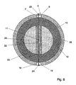
- the structure of various embodiments is shown in more detail in FIGS. 2 to 8:
- Each knife drum 1, 2 consists of a roller-shaped support body on the End faces the journal 8 for storage in the machine frame coaxially Roationsachse 11 are attached.
- the support body consists of two tubular, concentrically superimposed shells 12, 13 made of a fiber composite material, preferably a composite material made of carbon fibers and resin (CFRP fiber composite) are manufactured.
- the inner shell 12 is designed so that it required torsional rigidity guaranteed.
- the carbon fibers of the inner shell 12 crosswise in both a positive and a negative angle of 30 ° to 60 °, preferably 45 °, to the axis of rotation 11 of the support body wound.
- the outer shell 13 is constructed so that it has the required bending stiffness guaranteed.
- the carbon fibers in the outer shell are in a positive and / or negative angles of less than 30 °, preferably less than 10 °, in the example 5 ° to 8 °, wound to the axis of rotation 11. With these, for the bending stiffness
- the carbon fibers are advantageously small angles by winding layered on top of each other.
- the winding of the carbon fibers of the inner shell 12 is also preferably carried out crosswise, d. H. they are both in the positive as well wrapped in the negative small angles. At very small angles is close to 0 ° it is also possible to wind in one direction only.
- the wall thickness of the inner shell 12 is at least as large as the wall thickness of the Outer shell 13, preferably it is 1.1 times to 3 times the wall thickness of the Outer shell 13. If the fibers of the inner shell 12 have the same modulus of elasticity like the fibers of the outer shell 13, it is advantageous to have the inner shell 12 approximately to be twice as thick as the outer shell 13. In the embodiment, the Inner shell 12 with an inner diameter of 110 mm and a wall thickness of 40 mm, the outer shell 13 has a wall thickness of 20 mm.
- each groove 7 is located exclusively in the outer shell 13, from the Inner shell 12 thus no material is removed when milling the grooves 7.
- a groove 7 is a helical shape corresponding to the course of the groove 7 curved knife holder 6 made of metal, preferably made of steel, attached Elements for clamping a knife 5 and aligning the cutting edge having. The attachment of the knife 5 to the upper knife drum 1 and Lower knife drum 2 are shown in more detail in FIG. 3:
- the knife holder 6 is glued into the groove 7 of the outer shell 13. He has one plane, at a flat positive angle against the tangent to the support body inclined surface that serves as a support surface for the knife 5.
- the Knife 5 has a radially projecting cutting edge on the holder 6
- Fastening screws 14 screwed in the axial direction about every 50 mm are arranged.
- the drum length adjusting screws 15 stored in the knife holder 6 against the Press the rear edge of the knife 5.
- the outer surface of the outer shell 13 the knife drum at a distance of about 180 ° to the knife groove 7 a second Grooved groove 18.
- the second groove 18 extends approximately over the circumference equidistant from the knife groove 7, also in the form of a helix.
- a counterweight 19 is attached, which is designed so that the focus of the Knife drum lies on the axis of rotation 11.
- FIG. 4 shows a further embodiment of a knife drum according to the invention, in which three circumferentially equidistantly running in the outer surface of the outer shell 13 Grooves 7, 18, 20 are incorporated at a distance of approximately 120 ° each.
- a groove 7 is a knife holder 6 with a knife 5, in the other two grooves 18, 20, a counterweight 19 is attached in each case.
- the counterweights 19 are like this designed that both the center of gravity of the knife drum in the axis of rotation 11th runs, as well as the two main surface moments of inertia essentially the same are.
- This knife drum is particularly suitable for high-speed cross cutting machines suitable.
- the knife drums according to FIGS. 5, 6 and 7 each contain more than one Knife 5. They are especially designed for cutting short formats, because at one cycle twice (Figure 5, Figure 7) or three times (Figure 6).
- two grooves 7, 18 are at a distance of 180 ° and circumferentially equidistant in the form of a helix in the lateral surface the outer shell 13 incorporated.
- Figure 6 shows an embodiment with three grooves 7, 18, 20, which are at a distance extend equidistant circumferentially from 120 °. There is a knife holder in each groove 7, 18, 20 6 fastened with a knife 5. Because with one revolution of the knife drum is cut three times, the cutting rate can be with such a knife drum increase significantly.
- the knife drum according to Figure 7 contains four grooves 7, 18, 20, 21, in two opposite grooves 7, 20 each have a knife holder 6 with a knife 5, in the other two grooves 18, 21 at a distance of about 90 ° to the knife grooves 7, 20 counterweights 19 are attached.
- This knife drum is also for high Cutting rates designed, because cutting twice per revolution and at the same time by means of the counterweights distribute the moments of inertia very evenly over the circumference are.
- a knife drum is shown, the inside of the inner shell 12 axially over the drum length and radially over the inner cross section of the inner shell 12 extending web-shaped support element 22 contains.
- the support element 22 serves to absorb high cutting forces without the knife drum in radial Direction is deformed.
- the support element 22 therefore extends radially Direction to the knife 5 through the axis of rotation 11.
- this embodiment contains a second one in addition to the knife groove 7 Groove 18 at a distance of about 180 ° in which a counterweight 19 is attached.
- the knife 5 is fastened by means of a series of expansion screws 23 in the groove 7 itself through the knife drum and the support element 22 into corresponding Extend threaded holes in counterweight 19.
- the live ones Expansion screws 23 prevent that due to vibrations in operation Knife 5, the knife holder 6 and / or the counterweight 19 releases.
- the web-shaped support element 22 preferably also consists of fiber composite material, that by wrapping a plate-shaped winding core with radially extending Fibers was produced.
- the radially extending fibers of the support element 22 absorb the compressive forces acting on the knife holder 6 when cutting without that a deformation occurs in the radial direction of the knife drum.
- the knife drum of Figure 8 can advantageously be made so that the Support element 22 is part of the winding core on which the fibers of the inner shell 12 be wound up.
- the support element 22 is first manufactured and then supplemented with segments 25 made of a light material that the one for Coil core has the required rigidity and strength.
- the inner shell 12 is wrapped in layers by resin-impregnated carbon fibers produced, the segments 25 with the support element 22 remain in the inner shell 12 in the manner of a lost formwork.
- the outer shell 13 is applied, the grooves 7, 18 are in the Milled surface and the through holes for the expansion screws 23rd are drilled.
Landscapes
- Engineering & Computer Science (AREA)
- Mechanical Engineering (AREA)
- Life Sciences & Earth Sciences (AREA)
- Forests & Forestry (AREA)
- Paper (AREA)
- Storage Of Web-Like Or Filamentary Materials (AREA)
- Making Paper Articles (AREA)
- Storing, Repeated Paying-Out, And Re-Storing Of Elongated Articles (AREA)
Abstract
Description
- Figur 1
- zeigt schematisch einen Schnitt quer zur Bahnlaufrichtung durch eine Querschneidemaschine.
- Figur 2
- zeigt einen Querschnitt durch eine Messertrommel.
- Figur 3
- zeigt in einem Querschnitt die relative Anordnung der Obermessertrommel zur Untermessertrommel und die Befestigung der Messer.
- Die Figuren 3 bis 8
- zeigen weitere Ausführungsformen einer Messertrommel nach der Erfindung.
Claims (9)
- Messertrommel für eine Maschine zum Querschneiden von Materialbahnen, insbesondere Papier- oder Kartonbahnen, mit einem walzenförmigen Tragkörper aus einem Faserverbundmaterial, auf dessen Mantelfläche zumindest ein Halter (6) für ein sich über die Trommellänge erstreckendes Messer (5) befestigt ist, wobei der Tragkörper eine innere rohrförmige Schale (12) aus einem Faserverbundmaterial mit schräg zur Rotationsachse (11) kreuzweise gewickelten Fasern aufweist, dadurch gekennzeichnet, daß der Tragkörper aus zwei rohrförmigen, konzentrisch übereinander angeordneten Schalen (12, 13) aus Faserverbundmaterial besteht, wobeiund daß in die Mantelfläche der Außenschale (13) durch ein abtragendes Verfahren, insbesondere durch Fräsen, zumindest eine sich über die Trommellänge erstreckende Nut (7) eingearbeitet ist, in der der Messerhalter (6) befestigt ist.die Fasern in der Innenschale (12) in einem positiven und negativen Winkel von 30° bis 60°, vorzugsweise von 45°, zur Rotationsachse (11) des Tragkörpers kreuzweise gewickelt sind unddie Fasern in der Außenschale (13) in einem positiven und/oder negativen Winkel von weniger als 30°, vorzugsweise weniger als 10°, zur Rotationsachse (11) des Tragkörpers gewickelt sind,
- Messertrommel nach Anspruch 1, dadurch gekennzeichnet, daß die Wandstärke der Innenschale (12) zumindest so groß ist wie die Wandstärke der Außenschale (13).
- Vorrichtung nach Anspruch 2, dadurch gekennzeichnet, daß die Wandstärke der Innenschale (12) das 1,1-fache bis 3-fache der Wandstärke der Außenschale (13) beträgt.
- Messertrommel nach einem der Ansprüche 1 bis 3, dadurch gekennzeichnet, daß in die Mantelfläche der Außenschale (13) zwei Nuten (7, 18) in einem Abstand von etwa 180° eingearbeitet sind, wobei in einer Nut (7) ein Messerhalter (6) mit einem Messer (5), in der anderen Nut (18) ein Gegengewicht (19) oder ein Messerhalter (6) mit einem Messer (5) befestigt ist.
- Messertrommel nach einem der Ansprüche 1 bis 3, dadurch gekennzeichnet, daß in die Mantelfläche der Außenschale (13) drei Nuten (7, 18, 20) jeweils in einem Abstand von etwa 120° eingearbeitet sind, wobei in eine Nut (7) ein Messerhalter (6) mit einem Messer (5), in den beiden anderen Nuten (18, 20) jeweils ein Gegengewicht (19) oder ein Messerhalter (6) mit einem Messer (5) befestigt ist.
- Messertrommel nach einem der Ansprüche 1 bis 3, dadurch gekennzeichnet, daß in die Mantelfläche der Außenschale (13) vier Nuten (7, 18, 20, 21) eingearbeitet sind, wobei in zwei entgegengesetzt angeordneten Nuten (7, 20) jeweils ein Messerhalter (6) mit einem Messer (5), in den beiden anderen Nuten (18, 21) in einem Abstand von etwa 90° zu den Messernuten (7, 20) jeweils ein Gegengewicht (19) befestigt ist.
- Messertrommel nach einem der Ansprüche 1 bis 6, dadurch gekennzeichnet, daß im Innern der Innenschale (12) ein sich axial über die Trommellänge und radial über den Innenquerschnitt der Innenschale (12) erstreckendes stegförmiges Abstützelement (22) angeordnet ist, das in radialer Richtung zum Messer (5) durch die Rotationsachse (11) verläuft.
- Messertrommel nach Anspruch 7, dadurch gekennzeichnet, daß das stegförmige Abstützelement (22) aus Faserverbundmaterial besteht, das durch Umwickeln eines plattenförmiges Wickelkerns mit radial verlaufenden Fasern hergestellt wurde.
- Messertrommel nach Anspruch 7 oder 8, dadurch gekennzeichnet, daß der Messerhalter (6) mittels sich durch das Abstützelement (22) erstreckenden Dehnschrauben (23) in der Nut (7) der Außenschale (13) befestigt ist.
Applications Claiming Priority (3)
| Application Number | Priority Date | Filing Date | Title |
|---|---|---|---|
| DE19723513 | 1997-06-05 | ||
| DE19723513A DE19723513A1 (de) | 1997-06-05 | 1997-06-05 | Messertrommel für Maschinen zum Querschneiden von Materialbahnen |
| PCT/EP1998/001321 WO1998055276A1 (de) | 1997-06-05 | 1998-03-06 | Messertrommel für maschinen zum querschneiden von materialbahnen |
Publications (2)
| Publication Number | Publication Date |
|---|---|
| EP0986453A1 EP0986453A1 (de) | 2000-03-22 |
| EP0986453B1 true EP0986453B1 (de) | 2002-05-22 |
Family
ID=7831431
Family Applications (1)
| Application Number | Title | Priority Date | Filing Date |
|---|---|---|---|
| EP98921389A Expired - Lifetime EP0986453B1 (de) | 1997-06-05 | 1998-03-06 | Messertrommel für maschinen zum querschneiden von materialbahnen |
Country Status (6)
| Country | Link |
|---|---|
| US (1) | US6422113B1 (de) |
| EP (1) | EP0986453B1 (de) |
| JP (1) | JP3212620B2 (de) |
| DE (2) | DE19723513A1 (de) |
| ES (1) | ES2180166T3 (de) |
| WO (1) | WO1998055276A1 (de) |
Cited By (2)
| Publication number | Priority date | Publication date | Assignee | Title |
|---|---|---|---|---|
| DE202019101574U1 (de) | 2019-03-20 | 2020-06-30 | Bw Papersystems Hamburg Gmbh | Messertrommel |
| WO2020187647A1 (de) | 2019-03-20 | 2020-09-24 | Bw Papersystems Hamburg Gmbh | Messertrommel |
Families Citing this family (12)
| Publication number | Priority date | Publication date | Assignee | Title |
|---|---|---|---|---|
| JP4514126B2 (ja) * | 2004-10-01 | 2010-07-28 | 旭マシナリー株式会社 | 炭素繊維強化プラスチック製カッターロール用成形型 |
| JP5013799B2 (ja) * | 2006-09-27 | 2012-08-29 | 三菱重工印刷紙工機械株式会社 | ナイフシリンダ、ロータリカッタ、及びナイフ取り付け台の取り付け方法 |
| DE102007052586A1 (de) * | 2007-11-03 | 2009-05-07 | Schmidt & Heinzmann Gmbh & Co. Kg | Schneidvorrichtung |
| FR2979328B1 (fr) * | 2011-08-31 | 2014-05-16 | Martin | Dispositif pour traiter un element en plaque, unite de traitement et machine de fabrication d'emballage |
| FR3023199B1 (fr) * | 2014-07-03 | 2018-01-19 | Fives Dms | Dispositif de cisaillement |
| DE102015222181A1 (de) * | 2015-06-10 | 2016-12-15 | Sms Group Gmbh | Vorrichtung zum Wechseln eines Messers an einer Schere insbesondere für Walzband, und Schere mit zumindest einem auswechselbaren Messer |
| US10807263B2 (en) | 2016-12-07 | 2020-10-20 | The Procter & Gamble Company | Flexible curvilinear knife |
| US10471620B2 (en) | 2016-12-07 | 2019-11-12 | The Procter & Gamble Company | Knife having beam elements |
| US20190016004A1 (en) * | 2017-07-17 | 2019-01-17 | Elsner Engineering Works, Inc. | Thermal compensating mount for a knife roll in a web processing machine |
| DE102020130360A1 (de) | 2020-11-17 | 2022-05-19 | Manroland Goss Web Systems Gmbh | Messerzylinder und Messerbalken |
| KR20250120420A (ko) * | 2022-12-28 | 2025-08-08 | 봅스트 리옹 | 전환 기계용 플랩-절단 디바이스 |
| CN118081887A (zh) * | 2024-03-28 | 2024-05-28 | 杭州宏泰精密机械有限公司 | 一种横切机碳纤维筒体式切刀装置 |
Family Cites Families (25)
| Publication number | Priority date | Publication date | Assignee | Title |
|---|---|---|---|---|
| US1306009A (en) * | 1919-06-10 | hartman | ||
| US2180204A (en) * | 1937-11-27 | 1939-11-14 | Hallden Machine Company | Rotary cutting device |
| US3543622A (en) * | 1967-12-26 | 1970-12-01 | Polaroid Corp | Severing apparatus |
| US3822625A (en) * | 1973-02-09 | 1974-07-09 | Westvaco Corp | Rotary cutter with quick change knife |
| GB1536467A (en) * | 1975-01-17 | 1978-12-20 | Masson Scott Thrissell Eng Ltd | Rotary cutter drums |
| DE2622558B2 (de) * | 1976-05-20 | 1978-03-16 | Hoesch Werke Ag, 4600 Dortmund | Schere |
| US4130451A (en) * | 1977-04-29 | 1978-12-19 | Standard Oil Company (Indiana) | Process for the manufacture of filament wound pipe using deformable material at the wind stops |
| JPS5741920A (en) * | 1980-08-27 | 1982-03-09 | Mitsubishi Electric Corp | Manufacture of fiber-reinforced plastic product |
| DE8322639U1 (de) * | 1983-08-05 | 1983-12-01 | Uranit GmbH, 5170 Jülich | Leitwalzen für Papier-, Folienveredelungs- und Druckmaschinen |
| DE3432905A1 (de) * | 1984-09-07 | 1986-03-20 | Alfred Prof. Dr.-Ing. 3524 Immenhausen Puck | Verfahren zur verminderung der rissbildung von langgestreckten hohlkoerpern ... |
| JPS61194197A (ja) * | 1985-02-25 | 1986-08-28 | Mitsubishi Rayon Co Ltd | ローラー及びその製造方法 |
| DE3531786A1 (de) * | 1985-09-06 | 1987-03-19 | Klenk R Hartmetallwerkzeug | Fraeser fuer das umfangs- oder nutenfraesen von hochleistungsverbundwerkstoffen |
| DE3817174C1 (de) * | 1988-05-20 | 1989-04-06 | Uranit Gmbh, 5170 Juelich, De | |
| DE3831393A1 (de) | 1988-09-15 | 1990-03-22 | Wolfgang Prof Dr Ing Grebe | Traegerplatte |
| US5061533A (en) * | 1988-10-11 | 1991-10-29 | Mitsubishi Rayon Company Ltd. | Roll formed of carbon fiber composite material |
| DE8900516U1 (de) * | 1989-01-18 | 1989-03-09 | BHS-Bayerische Berg-, Hütten- und Salzwerke AG, 8000 München | Messerbalken für einen Querschneider für Warenbahnen, insbesondere Wellpappe |
| DE3926640A1 (de) * | 1989-08-11 | 1991-02-14 | Hunkeler Ag Jos | Vorrichtung zum querschneiden oder querperforieren von laufenden materialbahnen |
| DE9204618U1 (de) * | 1992-04-03 | 1992-05-27 | BHS-Bayerische Berg-, Hütten- und Salzwerke AG, 8000 München | Messerbalken für einen Querschneider für eine Warenbahn, insbesondere für Wellpappe |
| DE4223566C2 (de) * | 1992-07-17 | 1995-09-14 | Bielomatik Leuze & Co | Messerwalze für Schneideinrichtungen sowie Verfahren zur wenigstens teilfertigen Herstellung einer Messerwalze |
| DE4240232C2 (de) * | 1992-11-30 | 1995-04-27 | Bhs Corr Masch & Anlagenbau | Querschneider für Warenbahnen, insbesondere für eine Wellpappenbahn |
| DE4321163C3 (de) * | 1993-06-25 | 2000-07-13 | Freudenberg Carl Fa | Querschneider |
| US5383062A (en) * | 1993-10-18 | 1995-01-17 | Nippon Oil Co., Ltd. | CFRP-made optical cylinder |
| DE4417493A1 (de) * | 1994-05-19 | 1995-11-23 | Bielomatik Leuze & Co | Querschneider für Materialbahnen, insbesondere Papier-Formatquerschneider |
| DE19545003A1 (de) * | 1995-12-02 | 1997-06-05 | Jagenberg Papiertech Gmbh | Messertrommel für Maschinen zum Querschneiden von Materialbahnen und Verfahren zu ihrer Herstellung |
| DE19726993A1 (de) * | 1997-06-25 | 1999-01-07 | Jagenberg Papiertech Gmbh | Messertrommel für Maschinen zum Querschneiden von Materialbahnen |
-
1997
- 1997-06-05 DE DE19723513A patent/DE19723513A1/de not_active Withdrawn
-
1998
- 1998-03-06 DE DE59804200T patent/DE59804200D1/de not_active Expired - Lifetime
- 1998-03-06 EP EP98921389A patent/EP0986453B1/de not_active Expired - Lifetime
- 1998-03-06 US US09/424,946 patent/US6422113B1/en not_active Expired - Lifetime
- 1998-03-06 JP JP50136399A patent/JP3212620B2/ja not_active Expired - Lifetime
- 1998-03-06 WO PCT/EP1998/001321 patent/WO1998055276A1/de not_active Ceased
- 1998-03-06 ES ES98921389T patent/ES2180166T3/es not_active Expired - Lifetime
Cited By (2)
| Publication number | Priority date | Publication date | Assignee | Title |
|---|---|---|---|---|
| DE202019101574U1 (de) | 2019-03-20 | 2020-06-30 | Bw Papersystems Hamburg Gmbh | Messertrommel |
| WO2020187647A1 (de) | 2019-03-20 | 2020-09-24 | Bw Papersystems Hamburg Gmbh | Messertrommel |
Also Published As
| Publication number | Publication date |
|---|---|
| JP3212620B2 (ja) | 2001-09-25 |
| ES2180166T3 (es) | 2003-02-01 |
| JP2000512920A (ja) | 2000-10-03 |
| WO1998055276A1 (de) | 1998-12-10 |
| US6422113B1 (en) | 2002-07-23 |
| EP0986453A1 (de) | 2000-03-22 |
| DE59804200D1 (de) | 2002-06-27 |
| DE19723513A1 (de) | 1998-12-10 |
Similar Documents
| Publication | Publication Date | Title |
|---|---|---|
| DE69520938T2 (de) | Garnwickelhülsen | |
| EP0986453A1 (de) | Messertrommel für maschinen zum querschneiden von materialbahnen | |
| DE4414396A1 (de) | Trag- oder Stützwalze für eine Wickelmaschine | |
| DE60306431T2 (de) | Spiralförmiges rohr mit verstärkter steifigkeit des innendurchmessers und herstellungsverfahren dafür | |
| DE19603211A1 (de) | Walze für eine Wickelmaschine | |
| DE4321163C3 (de) | Querschneider | |
| DE602005006393T2 (de) | Wickelkern und zugehöriges verfahren | |
| DE19915224A1 (de) | Verfahren und Vorrichtung zum Außenrundschleifen dünnwandiger Rohre | |
| DE19726993A1 (de) | Messertrommel für Maschinen zum Querschneiden von Materialbahnen | |
| EP1380410B1 (de) | Riffelwalze sowie Verfahren zu deren Herstellung | |
| EP0735288A1 (de) | Kalanderwalze | |
| DE102008041268A1 (de) | Walze für Auftragseinrichtung und Verfahren zum Auswuchten einer Walze | |
| EP0878249B1 (de) | Verfahren zur Herstellung von zylindrischen Beschichtungsträgern | |
| EP1739040B1 (de) | Wickelmaschine | |
| DE102005000052A1 (de) | Wickelmaschine | |
| DE102013222896A1 (de) | Vorrichtung zum Wickeln einer Materialbahn zu einer mehrlagigen Rolle | |
| DE29613795U1 (de) | Walze mit optimiertem Biegeverhalten | |
| EP3946948B1 (de) | Druckmaschine, umfassend eine leitwalze zum führen einer materialbahn durch bestandteile der druckmaschine | |
| DE9420003U1 (de) | Trag- oder Stützwalze für eine Wickelmaschine | |
| DE19545003A1 (de) | Messertrommel für Maschinen zum Querschneiden von Materialbahnen und Verfahren zu ihrer Herstellung | |
| DE102004000033A1 (de) | Wickelmaschine | |
| EP1982938B1 (de) | Verfahren zum Bevorraten von flächigen, bahnförmigen Halbzeugen | |
| EP1176110B1 (de) | Verfahren und Wickelkern zur Vermeidung von Wickelfehlern in einer Materialbahn | |
| EP0886620B1 (de) | Vorrichtung zur kontinuierlichen aufrollung von längsgeschnittenen papierbahnen mit automatischem rollenwechsel bei maschinengeschwindigkeit | |
| DE2060261B2 (de) | Verfahren zum Herstellen eines Rohres aus faserverstärktem Kunststoff sowie Verfahren zur Durch führung des Verfahrens |
Legal Events
| Date | Code | Title | Description |
|---|---|---|---|
| PUAI | Public reference made under article 153(3) epc to a published international application that has entered the european phase |
Free format text: ORIGINAL CODE: 0009012 |
|
| 17P | Request for examination filed |
Effective date: 19990911 |
|
| AK | Designated contracting states |
Kind code of ref document: A1 Designated state(s): DE ES GB IT |
|
| GRAG | Despatch of communication of intention to grant |
Free format text: ORIGINAL CODE: EPIDOS AGRA |
|
| 17Q | First examination report despatched |
Effective date: 20010530 |
|
| GRAG | Despatch of communication of intention to grant |
Free format text: ORIGINAL CODE: EPIDOS AGRA |
|
| GRAH | Despatch of communication of intention to grant a patent |
Free format text: ORIGINAL CODE: EPIDOS IGRA |
|
| GRAH | Despatch of communication of intention to grant a patent |
Free format text: ORIGINAL CODE: EPIDOS IGRA |
|
| GRAA | (expected) grant |
Free format text: ORIGINAL CODE: 0009210 |
|
| REG | Reference to a national code |
Ref country code: GB Ref legal event code: FG4D Free format text: NOT ENGLISH |
|
| REF | Corresponds to: |
Ref document number: 59804200 Country of ref document: DE Date of ref document: 20020627 |
|
| GBT | Gb: translation of ep patent filed (gb section 77(6)(a)/1977) |
Effective date: 20020720 |
|
| RAP2 | Party data changed (patent owner data changed or rights of a patent transferred) |
Owner name: VOITH PAPER JAGENBERG GMBH |
|
| REG | Reference to a national code |
Ref country code: ES Ref legal event code: FG2A Ref document number: 2180166 Country of ref document: ES Kind code of ref document: T3 |
|
| PLBQ | Unpublished change to opponent data |
Free format text: ORIGINAL CODE: EPIDOS OPPO |
|
| PLBI | Opposition filed |
Free format text: ORIGINAL CODE: 0009260 |
|
| PLBF | Reply of patent proprietor to notice(s) of opposition |
Free format text: ORIGINAL CODE: EPIDOS OBSO |
|
| 26 | Opposition filed |
Opponent name: E.C.H. WILL GMBH Effective date: 20030221 |
|
| REG | Reference to a national code |
Ref country code: GB Ref legal event code: 732E |
|
| PLBB | Reply of patent proprietor to notice(s) of opposition received |
Free format text: ORIGINAL CODE: EPIDOSNOBS3 |
|
| RDAF | Communication despatched that patent is revoked |
Free format text: ORIGINAL CODE: EPIDOSNREV1 |
|
| APBP | Date of receipt of notice of appeal recorded |
Free format text: ORIGINAL CODE: EPIDOSNNOA2O |
|
| APBM | Appeal reference recorded |
Free format text: ORIGINAL CODE: EPIDOSNREFNO |
|
| APBQ | Date of receipt of statement of grounds of appeal recorded |
Free format text: ORIGINAL CODE: EPIDOSNNOA3O |
|
| APAH | Appeal reference modified |
Free format text: ORIGINAL CODE: EPIDOSCREFNO |
|
| APBU | Appeal procedure closed |
Free format text: ORIGINAL CODE: EPIDOSNNOA9O |
|
| PLCK | Communication despatched that opposition was rejected |
Free format text: ORIGINAL CODE: EPIDOSNREJ1 |
|
| PLBN | Opposition rejected |
Free format text: ORIGINAL CODE: 0009273 |
|
| STAA | Information on the status of an ep patent application or granted ep patent |
Free format text: STATUS: OPPOSITION REJECTED |
|
| 27O | Opposition rejected |
Effective date: 20061026 |
|
| REG | Reference to a national code |
Ref country code: DE Ref legal event code: R082 Ref document number: 59804200 Country of ref document: DE Representative=s name: VON ROHR PATENTANWAELTE PARTNERSCHAFT MBB, DE Ref country code: DE Ref legal event code: R082 Ref document number: 59804200 Country of ref document: DE |
|
| REG | Reference to a national code |
Ref country code: DE Ref legal event code: R082 Ref document number: 59804200 Country of ref document: DE Representative=s name: VON ROHR PATENTANWAELTE PARTNERSCHAFT MBB, DE |
|
| PGFP | Annual fee paid to national office [announced via postgrant information from national office to epo] |
Ref country code: GB Payment date: 20170322 Year of fee payment: 20 |
|
| PGFP | Annual fee paid to national office [announced via postgrant information from national office to epo] |
Ref country code: ES Payment date: 20170315 Year of fee payment: 20 |
|
| PGFP | Annual fee paid to national office [announced via postgrant information from national office to epo] |
Ref country code: IT Payment date: 20170323 Year of fee payment: 20 |
|
| PGFP | Annual fee paid to national office [announced via postgrant information from national office to epo] |
Ref country code: DE Payment date: 20170818 Year of fee payment: 20 |
|
| REG | Reference to a national code |
Ref country code: DE Ref legal event code: R071 Ref document number: 59804200 Country of ref document: DE |
|
| REG | Reference to a national code |
Ref country code: GB Ref legal event code: PE20 Expiry date: 20180305 |
|
| PG25 | Lapsed in a contracting state [announced via postgrant information from national office to epo] |
Ref country code: GB Free format text: LAPSE BECAUSE OF EXPIRATION OF PROTECTION Effective date: 20180305 |
|
| REG | Reference to a national code |
Ref country code: ES Ref legal event code: FD2A Effective date: 20201106 |
|
| PG25 | Lapsed in a contracting state [announced via postgrant information from national office to epo] |
Ref country code: ES Free format text: LAPSE BECAUSE OF EXPIRATION OF PROTECTION Effective date: 20180307 |