EP0986344B1 - Form zur herstellung eines zahnmodelles - Google Patents
Form zur herstellung eines zahnmodelles Download PDFInfo
- Publication number
- EP0986344B1 EP0986344B1 EP98929280A EP98929280A EP0986344B1 EP 0986344 B1 EP0986344 B1 EP 0986344B1 EP 98929280 A EP98929280 A EP 98929280A EP 98929280 A EP98929280 A EP 98929280A EP 0986344 B1 EP0986344 B1 EP 0986344B1
- Authority
- EP
- European Patent Office
- Prior art keywords
- peripheral wall
- mould according
- model
- mould
- impression
- Prior art date
- Legal status (The legal status is an assumption and is not a legal conclusion. Google has not performed a legal analysis and makes no representation as to the accuracy of the status listed.)
- Expired - Lifetime
Links
- 230000002093 peripheral effect Effects 0.000 claims abstract description 57
- 239000000463 material Substances 0.000 claims description 50
- 230000000295 complement effect Effects 0.000 claims description 9
- 239000007788 liquid Substances 0.000 claims description 8
- 238000007789 sealing Methods 0.000 claims description 7
- 238000004873 anchoring Methods 0.000 claims description 2
- 239000007789 gas Substances 0.000 claims 2
- 239000012530 fluid Substances 0.000 claims 1
- 238000012545 processing Methods 0.000 abstract description 5
- 239000012778 molding material Substances 0.000 abstract 1
- 238000004519 manufacturing process Methods 0.000 description 14
- 238000011161 development Methods 0.000 description 12
- 230000018109 developmental process Effects 0.000 description 12
- 238000011049 filling Methods 0.000 description 10
- 125000006850 spacer group Chemical group 0.000 description 6
- 238000005429 filling process Methods 0.000 description 3
- 210000001847 jaw Anatomy 0.000 description 3
- FHVDTGUDJYJELY-UHFFFAOYSA-N 6-{[2-carboxy-4,5-dihydroxy-6-(phosphanyloxy)oxan-3-yl]oxy}-4,5-dihydroxy-3-phosphanyloxane-2-carboxylic acid Chemical compound O1C(C(O)=O)C(P)C(O)C(O)C1OC1C(C(O)=O)OC(OP)C(O)C1O FHVDTGUDJYJELY-UHFFFAOYSA-N 0.000 description 2
- 229940072056 alginate Drugs 0.000 description 2
- 235000010443 alginic acid Nutrition 0.000 description 2
- 229920000615 alginic acid Polymers 0.000 description 2
- 239000003795 chemical substances by application Substances 0.000 description 2
- 238000004891 communication Methods 0.000 description 2
- 238000005553 drilling Methods 0.000 description 2
- 239000000428 dust Substances 0.000 description 2
- 238000005516 engineering process Methods 0.000 description 2
- 238000000034 method Methods 0.000 description 2
- 239000011505 plaster Substances 0.000 description 2
- 238000002360 preparation method Methods 0.000 description 2
- 238000011282 treatment Methods 0.000 description 2
- 241000397426 Centroberyx lineatus Species 0.000 description 1
- 206010062713 Haemorrhagic diathesis Diseases 0.000 description 1
- 239000005557 antagonist Substances 0.000 description 1
- 230000009286 beneficial effect Effects 0.000 description 1
- 230000015572 biosynthetic process Effects 0.000 description 1
- 230000007547 defect Effects 0.000 description 1
- 230000003292 diminished effect Effects 0.000 description 1
- 238000000227 grinding Methods 0.000 description 1
- 229910052602 gypsum Inorganic materials 0.000 description 1
- 239000010440 gypsum Substances 0.000 description 1
- 208000031169 hemorrhagic disease Diseases 0.000 description 1
- 230000002209 hydrophobic effect Effects 0.000 description 1
- 238000011221 initial treatment Methods 0.000 description 1
- 239000011810 insulating material Substances 0.000 description 1
- 238000002955 isolation Methods 0.000 description 1
- 238000011068 loading method Methods 0.000 description 1
- 239000012528 membrane Substances 0.000 description 1
- 239000002184 metal Substances 0.000 description 1
- 238000012986 modification Methods 0.000 description 1
- 230000004048 modification Effects 0.000 description 1
- 238000000465 moulding Methods 0.000 description 1
- 238000012354 overpressurization Methods 0.000 description 1
- 229920001296 polysiloxane Polymers 0.000 description 1
- 238000012805 post-processing Methods 0.000 description 1
- 238000004321 preservation Methods 0.000 description 1
- 210000001584 soft palate Anatomy 0.000 description 1
- 239000002689 soil Substances 0.000 description 1
- 239000007921 spray Substances 0.000 description 1
- 238000009966 trimming Methods 0.000 description 1
- 238000009423 ventilation Methods 0.000 description 1
- 239000000080 wetting agent Substances 0.000 description 1
Images



Classifications
-
- A—HUMAN NECESSITIES
- A61—MEDICAL OR VETERINARY SCIENCE; HYGIENE
- A61C—DENTISTRY; APPARATUS OR METHODS FOR ORAL OR DENTAL HYGIENE
- A61C9/00—Impression cups, i.e. impression trays; Impression methods
- A61C9/002—Means or methods for correctly replacing a dental model, e.g. dowel pins; Dowel pin positioning means or methods
Definitions
- the invention relates to a mold for producing a tooth model starting from a dental impression according to the preamble of claim 1.
- Such forms are known from DE-A-3837551.
- cup-shaped structures Such forms are known as cup-shaped structures.
- the dental impression is made with a plastic and hardening Model material poured out.
- Model material poured out.
- the model material is rare Falls, as long as the model material is still soft, one mostly rubber-like shape on the peripheral wall of the dental impression attached to refill by filling the mold up to a predetermined height a base surface on the tooth model to obtain.
- this base area mechanically parallel to the occlusal plane by grinding betrimmt; it results in a so-called sprocket Model material.
- the ring gear After hardening of the base and its mechanical trimming the ring gear is perpendicular to each through the individual groups of teeth given tangents so up sawing the base that the model teeth to be restored, Neighboring teeth, jaw segments or any other model teeth or model tooth groups removed from the socket individually and can be precisely reduced by the pins.
- Such a saw-cut model is a prerequisite for creation any kind of tooth set of dental impressions.
- model pedestals Another way of making model pedestals is by doing so in that the parallel trimmed conventionally produced Sprockets in a special drilling device be provided with the blind holes for the pins and at the same time mirror-image holes in a prefabricated Base plate made of plastic for holding the pins to be glued into the sprocket along with the Sprocket be drilled. The removal of the prepared Teeth are made in the conventional saw cut method. This is the elaborate processing a second plastic model mass for production Socket saved, but is an expensive equipment required.
- the invention is a mold for the preparation of a Tooth models created from a dental impression which allows a simpler process technology, in the case of only a smaller number of work steps too is done, and in their application, the number of sources of error is diminished and tooth models of higher precision to be obtained.
- the impression tray has at least sections of his Outside surface of a precisely given geometry and can without post-processing precise and tight with the peripheral wall be connected to the mold.
- the application of the inventive form is high Dimensions fault tolerant and can be largely automated.
- the invention also makes it possible that the tooth model already made directly at the dentist. This one needs only after making the dental impression the used Impression tray together with the impression itself in the Clamp the peripheral wall and in the shape thus obtained a sufficient amount of model material over the dental impression contribute. To the dental technician then only the so received tooth model passed.
- a mold according to claim 1 is closed tightly on all sides.
- a mold according to claim 1 also allows for simple Way the production of a tooth model, which on its base side already without mechanical processing of the Model material is plan.
- the invention allows a repeatable precise delivery of the model material to the form space.
- the development of the invention according to claim 3 is a bubble-free complete filling the Shape with model material.
- 6 or 7 can be simple and reliable way sealing connections between the Circumferential wall and the impression tray and / or the peripheral wall and realize the model plate.
- positioning pins use, which are embedded in the tooth model and one each over the tooth model protruding Have positioning.
- the outer surface or outer surface of the tooth model has a shape that is suitable for exact Positioning in an articulator or similar Device is suitable, without affecting the outer surface of the tooth model would have to be machined.
- the annoying production of plaster dust or dust from other model materials In order to deleted in the dental laboratory when using a novel Total form the annoying production of plaster dust or dust from other model materials.
- Figures 1 and 2 is a mold for manufacturing of dental models, the total of 10 is designated.
- the mold 10 has a peripheral wall 12, the lower section of which is complementary to the outer surface an impression tray 14 is.
- the illustrated impression tray 14 is a spoon for Production of maxillary impressions and has a bottom wall 18 with a medial, the soft palate emulated Wall section 20 and extending in the circumferential direction Edge wall 22. At the edge of the wall portion 20 and at the top End of the edge wall 22 are soldered wire pieces 24th or 26 provided by which undercuts be created, where a dental impression 28 locked which is e.g. made of silicone, alginate or the like.
- a longitudinal direction extending groove 30 is provided, in which a longitudinally extending rib 32 positively engages provided on the inner surface of the peripheral wall 12 is.
- the contour corresponds the inner surface of the peripheral wall 12 of the contour of the outer surface the edge wall 22, which also for sealing and good positioning.
- the goes Outer surface of the peripheral wall 12 smooth in the outer surface of the impression tray 14 via.
- the outer surface of the peripheral wall 12 extends obliquely inclined outside, so that the strength of the peripheral wall 12th increases towards the top.
- peripheral wall 12, the impression tray 14 and of this worn dental impression 28 and the model plate 38 thus limit together a sealed to the outside Mold cavity 42.
- the peripheral wall 12 is provided with a slot 44.
- the Peripheral wall 12 is made of a substantially rigid but something elastically deformable plastic material made, so that the peripheral wall 12 below through Slot 44 allows elastic expansion on the Impression tray 14 clipped or removed from this can be.
- the lower wall portion of the peripheral wall in FIG 12 has two in the vicinity of the slot 44 Swallowtail parts 46, 48, whose dovetail surfaces 50 down to be wider. You push on the Dovetail surfaces 50 a clamping part 52, which with complementary internal dovetail surfaces 54 is provided, then the peripheral wall 12 at the slot 44 contracted and thus in tight and tight plant brought to the outer surface of the impression tray 14. at the same time is a lying between the side surfaces of the slot 44 Seal 53 under pretensioned.
- the peripheral wall 12 In the outer areas of the lower wall section the peripheral wall 12 are two connecting pieces 56, 58 are provided. Of these, the left is with the outlet of one Reservoir 60 tightly connected, the liquid Model material (eg gypsum) contains. A ventilation connection of the reservoir 60 is via an adjustable Throttle 62 in communication with the environment.
- the liquid Model material eg gypsum
- the connecting piece 58 includes a plug 64, the gas permeable, for model material, however, a Lock represents.
- the plug 64 is the connection piece 58 connected to the suction port of a suction pump 66. Their outlet is also with the ambient atmosphere in connection.
- FIGS. 1, 2 and 6 FIG from the mold cavity 42 remote boundary surface of the Model plate 38 radial positioning ribs 68, which have essentially triangular basic cross-section and fall off towards the center of the model plate 38.
- the positioning ribs 68 work with complementary positioning grooves a holding member, not shown, together common for split magnetic base systems.
- the holding part is in turn in the articulator or a processing device clamped by the dental technician.
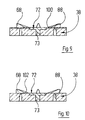
- model plate 38 carries 38 within a shallow recess open towards the rim 70 a disc-shaped fixing member 72 with a in the Model plate embedded shaft 73 of magnetic or magnetizable material, which with a counter-fixing part cooperates, carried by the holding part is and also made of magnetic or magnetizable Material exists.
- the model plate 38 releasably fixed on the holding part.
- the mold cavity 42 is first evacuated, and then The model material is fed under overpressure.
- a compressor 104 and a 2/2 or a 3/2-way solenoid valve 106 or 108 used by a suitable controller 110 are actuated.
- Pressure regulator 112 and 114 are used to specify the Vacuum and the pressure in the mold cavity 42. This variant is in Figure 1 shown in dashed lines.
- the filling process can visually through the model plate 38th and / or the peripheral wall 12 are controlled.
- By additional shaking or vibrating the mold 10 can you even the filling process and about under Model material in the depressions of the dental impression Bring 28 trapped air bubbles up.
- a mechanical vibrator 74 which is mechanically coupled to the mold 10, such as indicated by dashed lines in Figure 1.
- the plug 64 At the end of the filling process then reaches the liquid Model material the plug 64. Since it does not prevail can, the suction pump 66 is now working against closed volume, which is acoustically good wahnappelbar is. If desired, you can to the between the plug 64 and the suction pump 66 extending line also a Connect the pressure switch 76, whose output signal to the Alarm can be used.
- the positioning pins 78 each have an anchoring portion 84, which is poured into the model material and to improve the adhesion with a Knurling is provided with grooves or the like. Further the positioning pins 78 have frusto-conical positioning sections 86, which are complementary to Sackaus traditions 88 which are in raster arrangement on the mold cavity side Boundary surface of the model plate 38 are provided. In Figure 5 are four different removable segments 90a, 90b, 90c and 90d of the tooth model 80, the two cavities receding from the occlusal surface, a truncated conical crown preparation and a correspond to lateral cavity of a tooth.
- the inner and outer edge contour of the inner and outer edge contour the upper end of the peripheral wall 12 corresponds.
- the lower one End face of the spacer element 92 is complementary to upper end surface of the peripheral wall 12, and the upper End face of the spacer element 92 has the same geometry as the upper end surface of the peripheral wall 12th
- Another seal 94 provides a seal between the spacer element 92 and the model plate 38. It understands itself that the dentist or the dental technician a plurality of spacers 92 maintains the height of the mold cavity 42 as close as possible to the required height of the Tooth model to be able to choose. To set stronger Enlarged mold cavity 42 can also be several stack such spacers one above the other.
- FIG. 8 shows a modified model plate 38, which is provided with a channel 96. This channel is over a plug 98 having the same characteristics like the plug 64, with the suction side of the suction pump 66 connected.
- model plate 38 also be provided with a plurality of such channels 96, each with an associated plug 98 with the Suction pump 66 are provided.
- the pressurization of the mold cavity 42 during Filling the model material is obtained according to FIG 11 characterized in that the inlet of the throttle 62 with the Outlet of a compressor 104 connects.
- the stopper 64 is then in direct flow communication with the ambient atmosphere.
- the overpressure feed of the model material a syringe or a mechanical delivery pump use.
- model plate 38 and peripheral wall 12 provide a positive connection, e.g. one of the Groove 30 corresponding groove in the outer surface of the mounting plate 38 and one of the side wall of the edge recess 36th supported rib, which corresponds to the Ripppe 32.
- one of the mold cavity 42 limiting Surfaces before feeding the model material with a suitable release agent covers eg release agent spray
- a suitable release agent covers eg release agent spray
Landscapes
- Health & Medical Sciences (AREA)
- General Health & Medical Sciences (AREA)
- Dentistry (AREA)
- Epidemiology (AREA)
- Life Sciences & Earth Sciences (AREA)
- Animal Behavior & Ethology (AREA)
- Oral & Maxillofacial Surgery (AREA)
- Public Health (AREA)
- Veterinary Medicine (AREA)
- Dental Tools And Instruments Or Auxiliary Dental Instruments (AREA)
- Moulds For Moulding Plastics Or The Like (AREA)
- Instructional Devices (AREA)
- Dental Prosthetics (AREA)
- Gears, Cams (AREA)
Description
Derartige Formen sind aus DE-A-3837551 bekannt.
- Figur 1:
- Eine Aufsicht auf eine Form zum Herstellen von Zahnmodellen zusammen mit einer schematisch dargestellten Einrichtung zum Füllen der Form mit Modellmaterial, wobei ein Teil einer die Oberseite der Form bildenden Modellplatte weggebrochen ist;
- Figur 2:
- Einen transversalen Schnitt durch die in Figur 1 gezeigte Form längs der abgewinkelten Schnittlinie II-II von Figur 1;
- Figur 3:
- Eine Aufsicht auf die modellseitige Begrenzungsfläche der Modellplatte von Figuren 1 und 2;
- Figur 4:
- Einen Längsschnitt durch die Modellplatte längs der Schnittlinie IV-IV von Figur 3;
- Figur 5:
- Eine Aufsicht auf die modellseitige Begrenzungsfläche der Modellplatte mit einem von dieser getragenen zersägten Zahnkranz eines Kieferbogens;
- Figur 6:
- Eine Aufsicht auf die halterungsseitige Begrenungsfläche der in Figur 5 gezeigten Modellplatte;
- Figur 7:
- Einen zur Figur 2 ähnlichen Schnitt durch eine abgewandelte Form, die zur Herstellung höherer Zahnmodelle dient;
- Figur 8:
- Eine ähnliche Ansicht wie Figur 3, in welcher eine abgewandelte Modellplatte wiedergegeben ist;
- Figuren 9 und 10:
- Schnitte durch weiter abgewandelte Modellplatten, die ähnlich gelegt sind wie der Schnitt von Figur 2; und
- Figur 11:
- Eine ähnliche Absicht wie Figur 1, in welcher jedoch eine abgewandelte Einrichtung zum Füllen der Form mit Modellmaterial wiedergegeben ist.
Claims (18)
- Form zur Herstellung eines Zahnmodelles ausgehend von von einem Zahnabdruck, mit einer den Zahnabdruck (28) aufnehmenden Unterform, welche eine Umfangswand (12) und eine Bodenwand aufweist, wobei die Umfangswand (12) dicht mit einem die Bodenwand bildenden und den Zahnabdruck (28) tragenden Abdrucklöffel (14) verbunden ist und auf das obere Ende der Umfangswand (12) eine Modellplatte (38) dicht aufsetzbar ist, dadurch gekennzeichnet, daß die Umfangswand (12) und die Modellplatte (38) zusammen mindestens zwei Fluidöffnungen (56, 58, 96) wobei mindestens eine der Fluidöffnungen mit einer Quelle (60) für Modellmaterial im Verbindung steht aufweisen, die mit dem durch die Umfangswand (12) den Abdrucklöffel (14) und die Modellplatte (38) begrenzten Formhohlraum (42) in Verbindung stehen.
- Form nach Anspruch 1, dadurch gekennzeichnet, daß die Fluidöffnungen (56, 58, 96) der formseitigen Begrenzungsfläche der Modellplatte (38) benachbart sind.
- Form nach Anspruch 1 oder 2, dadurch gekennzeichnet, daß die Fluidöffnungen (56, 58, 96) mit einander strömungsmäßig gegenüberliegenden Abschnitten des Formhohlraumes (42) in Verbindung stehen.
- Form nach einem der Ansprüche 1 bis 3, dadurch gekennzeichnet, daß mindestens eine der Fluidöffnungen (56, 58, 96) einen Stopfen (64, 98) aufweist, welcher für Gas, nicht jedoch für Modellmaterial durchlässig ist.
- Form nach einem der Ansprüche 1 bis 4, dadurch gekennzeichnet, daß die Dichtverbindung zwischen der Umfangswand (12) und dem Abdrucklöffel (14) zusammenarbeitende Formschlußmittel (30, 32) aufweist, die auf der Innenseite der Umfangswand (12) bzw. auf der Außenseite des Abdrucklöffels (14) vorgesehen sind.
- Form nach einem der Ansprüche 1 bis 5, dadurch gekennzeichnet, daß die Dichtverbindung zwischen der Umfangswand (12) und dem Abdrucklöffel (14) zueinander komplementäre Oberflächenabschnitte der Innenfläche der Umfangswand (12) bzw. der Außenfläche des Abdrucklöffels (14) umfaßt.
- Form nach einem der Ansprüche 1 bis 6, dadurch gekennzeichnet, daß die Dichtverbindung zwischen der Umfangswand (12) und dem Abdrucklöffel (14) mindestens ein Dichtelement (34) umfaßt.
- Form nach einem der Ansprüche 1 bis 7, dadurch gekennzeichnet, daß die Modellplatte (38) formschlüssig in eine Ausnehmung (36) eingreift, die in der oberen Stirnfläche der Umfangswand (12) vorgesehen ist.
- Form nach einem der Ansprüche 1 bis 8, dadurch gekennzeichnet, daß die Modellplatte (38) mit einer Vielzahl in einem Raster angeordneter hinterschneidungsfreier Sackausnehmungen (88) versehen ist, wobei sich letztere vorzugsweise zum Sackausnehmungsboden hin verjüngen.
- Form nach Anspruch 9, gekennzeichnet durch Positionierstifte (78), welche einen zu den Sackausnehmungen (88) komplementären Positionierabschnitt (86) und einen fest in das Modellmaterial einbettbaren Verankerungsabschnitt (84) aufweisen.
- Form nach Anspruch 9, dadurch gekennzeichnet, daß ein oberer Abschnitt der Sackausnehmungen, vorzugsweise der Boden der Sackausnehmungen für Gase, nicht jedoch für Modellmaterial durchlässig ist.
- Form nach einem der Ansprüche 1 bis 11, gekennzeichnet durch eine Einrichtung (66; 104) zum Erzeugen eines Druckunterschiedes zwischen mindestens zweien der Fluidöffnungen (56, 58, 96).
- Form nach einem der Ansprüche 1 bis 12, gekennzeichnet durch ein Verlängerungsteil (92) für die Umfangswand (12), dessen untere Stirnfläche zur oberen Stirnfläche der Umfangswand komplementär ist und dessen obere Stirnfläche der Umfangswand (12) entspricht.
- Form nach einem der Ansprüche 1 bis 13, dadurch gekennzeichnet, daß die Umfangswand (12) einen sie in Umfangsrichtung unterbrechenden Schlitz (44) aufweist, und daß dem Schlitz (44) eine Spanneinrichtung (46 bis 50) zugeordnet ist.
- Form nach Anspruch 14, dadurch gekennzeichnet, daß dem dem Schlitz (44) eine Dichteinrichtung (53) zugeordnet ist.
- Form nach einem der Ansprüche 1 bis 15, dadurch gekennzeichnet, daß die Umfangswand (12) aus transparentem oder transluzentem Material hergestellt ist.
- Form nach einem der Ansprüche 1 bis 16, dadurch gekennzeichnet, daß die Modellplatte (38) aus transparentem oder transluzentem Material hergestellt ist.
- Form nach einem der Ansprüche 1 bis 17, dadurch gekennzeichnet, daß die Innenfläche des oberen Abschnittes der Umfangswand (12) die Form eines Polygons hat.
Applications Claiming Priority (3)
| Application Number | Priority Date | Filing Date | Title |
|---|---|---|---|
| DE19722989 | 1997-05-25 | ||
| DE19722989A DE19722989C1 (de) | 1997-05-25 | 1997-05-25 | Form zur Herstellung eines Zahnmodelles |
| PCT/EP1998/002601 WO1998052491A1 (de) | 1997-05-25 | 1998-05-02 | Form zur herstellung eines zahnmodelles |
Publications (2)
| Publication Number | Publication Date |
|---|---|
| EP0986344A1 EP0986344A1 (de) | 2000-03-22 |
| EP0986344B1 true EP0986344B1 (de) | 2005-08-03 |
Family
ID=7831130
Family Applications (1)
| Application Number | Title | Priority Date | Filing Date |
|---|---|---|---|
| EP98929280A Expired - Lifetime EP0986344B1 (de) | 1997-05-25 | 1998-05-02 | Form zur herstellung eines zahnmodelles |
Country Status (8)
| Country | Link |
|---|---|
| US (1) | US6217326B1 (de) |
| EP (1) | EP0986344B1 (de) |
| JP (1) | JP2001525709A (de) |
| AT (1) | ATE300921T1 (de) |
| AU (1) | AU727446B2 (de) |
| CA (1) | CA2290979A1 (de) |
| DE (2) | DE19722989C1 (de) |
| WO (1) | WO1998052491A1 (de) |
Families Citing this family (32)
| Publication number | Priority date | Publication date | Assignee | Title |
|---|---|---|---|---|
| DE19852056A1 (de) * | 1998-11-11 | 2000-05-18 | Duerr Dental Gmbh Co Kg | Dentaler Abformlöffel sowie Abformmaterial zur Verwendung mit einem solchen |
| FR2805452B1 (fr) * | 2000-02-25 | 2003-05-30 | Dentalmatic Technologies Inc | Modele pour la prise d'empreinte tridimensionnelle d'une zone d'arcade dentaire destinee a recevoir une prothese, et procede pour la mise en oeuvre de ce modele |
| DE10114493B4 (de) * | 2001-03-25 | 2007-07-19 | Jan Langner Gmbh | Verfahren und Vorrichtung zum Auftrennen zahntechnischer Modelle |
| US20060210944A1 (en) * | 2002-07-01 | 2006-09-21 | Yunoh Jung | Dental modeling and articulating system and method |
| US20060216667A1 (en) * | 2002-07-01 | 2006-09-28 | Yunoh Jung | Dental modeling and articulating system and method |
| US6932608B1 (en) | 2003-05-21 | 2005-08-23 | Gbase, Inc. | Two-piece model and die system |
| EP1734890A4 (de) * | 2004-02-20 | 2008-07-16 | James K Garland | Dentalmodellschale und artikulator |
| US7922490B2 (en) * | 2004-12-14 | 2011-04-12 | Align Technology, Inc. | Base for physical dental arch model |
| US20060127859A1 (en) * | 2004-12-14 | 2006-06-15 | Huafeng Wen | Producing a physical toothmodel compatible with a physical dental arch model |
| US20070092853A1 (en) * | 2005-10-24 | 2007-04-26 | Liu Frank Z | Multi-layer casting methods and devices |
| US8636513B2 (en) * | 2004-12-14 | 2014-01-28 | Align Technology, Inc. | Fabricating a base compatible with physical tooth models |
| US20060172250A1 (en) * | 2005-02-03 | 2006-08-03 | Huafeng Wen | Inelligent tracking of dental devices |
| WO2006091982A2 (en) * | 2005-02-25 | 2006-08-31 | Yunoh Jung | Dental modeling and articulating system and method |
| US20060275731A1 (en) | 2005-04-29 | 2006-12-07 | Orthoclear Holdings, Inc. | Treatment of teeth by aligners |
| WO2008103481A1 (en) * | 2007-02-23 | 2008-08-28 | Yunoh Jung | Dental modeling system with drillable tray base |
| DE102011057029A1 (de) | 2011-12-23 | 2013-06-27 | Degudent Gmbh | Verfahren zum Herstellen eines zahntechnischen Modells, Tragplatte zur Aufnahme von einem Gebissmodell sowie zahntechnische Einrichtung |
| US10568720B2 (en) | 2012-01-10 | 2020-02-25 | Estetic Implant Solutions, LLC | Dental implants with markers for determining three-dimensional positioning |
| US10709525B2 (en) | 2012-01-10 | 2020-07-14 | Esthetic Implant Solutions, Llc | Methods for taking an oral scan without requiring removal of a temporary healing abutment |
| US10016260B2 (en) | 2012-01-10 | 2018-07-10 | Mark H. Blaisdell | Anatomical healing abutments, kits, and methods |
| US10595970B2 (en) | 2012-01-10 | 2020-03-24 | Esthetic Implant Solutions, Llc | Bonding of soft gingival tissues with anatomical and other dental prostheses |
| US10507081B2 (en) | 2012-01-10 | 2019-12-17 | Esthetic Implant Solutions, Llc | Methods for taking an impression or scanning without requiring removal of a temporary healing abutment |
| US8628327B1 (en) * | 2012-10-02 | 2014-01-14 | Mark H. Blaisdell | Casting jig for chair-side manufacture of customizable sculptable anatomical healing caps |
| US11253345B2 (en) | 2012-01-10 | 2022-02-22 | Esthetic Implant Solutions, Llc | Methods for integrating scans including 3D cone beam scan for positioning of implant and fabrication of dental prosthesis |
| US12491053B2 (en) | 2012-01-10 | 2025-12-09 | Esthetic Implant Solutions, Llc | Methods for integrating scans including 3D cone beam scan for positioning of implant and fabrication of dental prosthesis |
| US9895209B2 (en) | 2012-01-10 | 2018-02-20 | Mark H. Blaisdell | Casting jig including elongate handle for chair-side manufacture of customizable sculptable anatomical healing caps, and method for forming bis-acrylic crown |
| US9572640B2 (en) | 2012-10-02 | 2017-02-21 | Mark H. Blaisdell | Casting jig for chair-side manufacture of customizable sculptable anatomical healing caps |
| CN108324393B (zh) * | 2018-03-19 | 2023-08-04 | 浙江大学 | 采用牙齿咬模片的普适性牙齿夹模器 |
| US11559379B2 (en) | 2018-04-12 | 2023-01-24 | Esthetic Implant Solutions, Llc | Dental implants with markers for determining three-dimensional positioning |
| RU2686369C1 (ru) * | 2018-08-03 | 2019-04-25 | Федеральное государственное автономное образовательное учреждение высшего образования "Сибирский федеральный университет" | Регулятор давления в кювете |
| IT202100026813A1 (it) | 2021-10-19 | 2023-04-19 | Dentag Italia Srl | Piastra composta per la costruzione di modelli dentali |
| DE202023105258U1 (de) | 2023-09-12 | 2023-09-28 | Dentag Italia Srl | 3d-gedrucktes Zahnmodell mit Trägerplatte |
| USD1125379S1 (en) | 2024-04-01 | 2026-05-05 | Hasbro, Inc. | Teeth for a toy system |
Family Cites Families (9)
| Publication number | Priority date | Publication date | Assignee | Title |
|---|---|---|---|---|
| US3161917A (en) * | 1963-04-12 | 1964-12-22 | Wiland Lawrence | Molding flask for dental impressions |
| US4203219A (en) * | 1978-08-08 | 1980-05-20 | Carl Dorf | Dental model assembly and production method |
| US4300884A (en) * | 1980-02-28 | 1981-11-17 | Hector Camacho | Casting collar for dental impression tray |
| DE8313606U1 (de) * | 1983-05-07 | 1985-10-03 | Heynold, Wolfgang, 6000 Frankfurt | Vorrichtung für die Durchführung eines Verfahrens zur Herstellung eines Gebißmodelles |
| US4721464A (en) * | 1985-06-17 | 1988-01-26 | Roden Mack L | Method and apparatus for making a dental model |
| DE3837551A1 (de) * | 1988-11-04 | 1990-05-10 | Schreiber Hans | Vorrichtung zum herstellen zahntechnischer kiefermodelle in form von saegeschnittmodellen nebst bausatz hierzu |
| US5129822A (en) * | 1990-03-19 | 1992-07-14 | Dobbs T Charles | Dental casting apparatus and method |
| IT1273016B (it) * | 1994-07-27 | 1997-07-01 | Gaetano Squicciarini | "corredo di elementi per la colatura per la realizzazione di modelli di gesso per protesi dentarie, e sistemi di colatura che impiegano tali elementi". |
| US6106284A (en) * | 1999-01-15 | 2000-08-22 | Cronin; Richard J. | Dental cast tray assembly |
-
1997
- 1997-05-25 DE DE19722989A patent/DE19722989C1/de not_active Expired - Fee Related
-
1998
- 1998-05-02 CA CA002290979A patent/CA2290979A1/en not_active Abandoned
- 1998-05-02 AT AT98929280T patent/ATE300921T1/de not_active IP Right Cessation
- 1998-05-02 AU AU79105/98A patent/AU727446B2/en not_active Ceased
- 1998-05-02 DE DE59812979T patent/DE59812979D1/de not_active Expired - Fee Related
- 1998-05-02 WO PCT/EP1998/002601 patent/WO1998052491A1/de not_active Ceased
- 1998-05-02 US US09/424,693 patent/US6217326B1/en not_active Expired - Fee Related
- 1998-05-02 JP JP54986898A patent/JP2001525709A/ja active Pending
- 1998-05-02 EP EP98929280A patent/EP0986344B1/de not_active Expired - Lifetime
Also Published As
| Publication number | Publication date |
|---|---|
| US6217326B1 (en) | 2001-04-17 |
| JP2001525709A (ja) | 2001-12-11 |
| DE19722989C1 (de) | 1999-02-25 |
| DE59812979D1 (de) | 2005-09-08 |
| ATE300921T1 (de) | 2005-08-15 |
| AU727446B2 (en) | 2000-12-14 |
| EP0986344A1 (de) | 2000-03-22 |
| CA2290979A1 (en) | 1998-11-26 |
| AU7910598A (en) | 1998-12-11 |
| WO1998052491A1 (de) | 1998-11-26 |
Similar Documents
| Publication | Publication Date | Title |
|---|---|---|
| DE19722989C1 (de) | Form zur Herstellung eines Zahnmodelles | |
| DE2856963C1 (de) | Vorrichtung zum Herstellen eines zahntechnischen Arbeitsmodelles fuer die Anfertigung von prothetischen Arbeiten | |
| EP0884981B1 (de) | Vorrichtung zum herstellen von zahnabdrücken und abformlöffel hierfür | |
| EP0116163B1 (de) | Gebissmodell und Sockelplatte für ein Gebissmodell | |
| DE3521137A1 (de) | Gebissmodell und verfahren zu seiner herstellung | |
| EP2384718A2 (de) | Dentalmodellrohling | |
| EP3572035B1 (de) | Dentalprothese, zugehöriges halbprodukt sowie bausatz | |
| EP0565847B1 (de) | Vorrichtung für eine Wurzelspitzenresektion | |
| EP3285681A1 (de) | Vorrichtung und verfahren zur halterung von prothesenzähnen | |
| DE212008000025U1 (de) | Injektionskorrekturabformlöffel | |
| EP0282905B1 (de) | Verfahren und Vorrichtungen zur Herstellung porenfreier Zahnformkörper | |
| DE19954732C2 (de) | Halter für ein Modell | |
| DE3410487A1 (de) | Vorrichtung und verfahren zum anfertigen von vorabdruecken fuer zahnersatz | |
| DE3440745A1 (de) | Gebissmodell und verfahren zu seiner herstellung | |
| DE3918497A1 (de) | Artikulator fuer die zahntechnik sowie arbeitsverfahren dazu | |
| DE3326222C1 (de) | Vorrichtung zum Abformen von Kronenstümpfen und Einlagefüllungspräparationen in der Zahnheilkunde | |
| EP1008328A2 (de) | Interdentalwerkzeug | |
| DE4116109A1 (de) | Verfahren zum herstellen eines abdruckes von einem bezahnten, menschlichen kiefer | |
| DE4110672C2 (de) | Sockelvorrichtung zur Herstellung und Halterung eines Gipsmodelles eines Zahnkranzes | |
| DE366104C (de) | Verfahren zur Herstellung von Gebissmodellen | |
| DE102020126122A1 (de) | Verfahren zur Herstellung einer kieferorthopädischen Apparatur | |
| DE3311673A1 (de) | Verfahren und vorrichtung zur herstellung eines gebissmodelles | |
| DE3727668A1 (de) | Verfahren zur herstellung eines gebisspositioners und einrichtungen zu seiner durchfuehrung | |
| DE2646364A1 (de) | Verfahren und vorrichtung zum aufbau einer zahnprothese in situ | |
| DE102016011619A1 (de) | Nicht invasive Zahnbrücken und Totalprothesen, die in ihrem Aussehen dem natürlichen Gebiss vollständig gleichen. |
Legal Events
| Date | Code | Title | Description |
|---|---|---|---|
| PUAI | Public reference made under article 153(3) epc to a published international application that has entered the european phase |
Free format text: ORIGINAL CODE: 0009012 |
|
| 17P | Request for examination filed |
Effective date: 19991110 |
|
| AK | Designated contracting states |
Kind code of ref document: A1 Designated state(s): AT CH DE ES FR GB IT LI SE |
|
| 17Q | First examination report despatched |
Effective date: 20031219 |
|
| GRAP | Despatch of communication of intention to grant a patent |
Free format text: ORIGINAL CODE: EPIDOSNIGR1 |
|
| GRAS | Grant fee paid |
Free format text: ORIGINAL CODE: EPIDOSNIGR3 |
|
| GRAA | (expected) grant |
Free format text: ORIGINAL CODE: 0009210 |
|
| AK | Designated contracting states |
Kind code of ref document: B1 Designated state(s): AT CH DE ES FR GB IT LI SE |
|
| PG25 | Lapsed in a contracting state [announced via postgrant information from national office to epo] |
Ref country code: GB Free format text: LAPSE BECAUSE OF FAILURE TO SUBMIT A TRANSLATION OF THE DESCRIPTION OR TO PAY THE FEE WITHIN THE PRESCRIBED TIME-LIMIT Effective date: 20050803 |
|
| REG | Reference to a national code |
Ref country code: GB Ref legal event code: FG4D Free format text: NOT ENGLISH |
|
| REG | Reference to a national code |
Ref country code: CH Ref legal event code: EP |
|
| REF | Corresponds to: |
Ref document number: 59812979 Country of ref document: DE Date of ref document: 20050908 Kind code of ref document: P |
|
| PG25 | Lapsed in a contracting state [announced via postgrant information from national office to epo] |
Ref country code: SE Free format text: LAPSE BECAUSE OF FAILURE TO SUBMIT A TRANSLATION OF THE DESCRIPTION OR TO PAY THE FEE WITHIN THE PRESCRIBED TIME-LIMIT Effective date: 20051103 |
|
| PG25 | Lapsed in a contracting state [announced via postgrant information from national office to epo] |
Ref country code: ES Free format text: LAPSE BECAUSE OF FAILURE TO SUBMIT A TRANSLATION OF THE DESCRIPTION OR TO PAY THE FEE WITHIN THE PRESCRIBED TIME-LIMIT Effective date: 20051114 |
|
| GBV | Gb: ep patent (uk) treated as always having been void in accordance with gb section 77(7)/1977 [no translation filed] |
Effective date: 20050803 |
|
| PG25 | Lapsed in a contracting state [announced via postgrant information from national office to epo] |
Ref country code: AT Free format text: LAPSE BECAUSE OF NON-PAYMENT OF DUE FEES Effective date: 20060502 |
|
| PG25 | Lapsed in a contracting state [announced via postgrant information from national office to epo] |
Ref country code: LI Free format text: LAPSE BECAUSE OF NON-PAYMENT OF DUE FEES Effective date: 20060531 Ref country code: CH Free format text: LAPSE BECAUSE OF NON-PAYMENT OF DUE FEES Effective date: 20060531 |
|
| PGFP | Annual fee paid to national office [announced via postgrant information from national office to epo] |
Ref country code: IT Payment date: 20060531 Year of fee payment: 9 |
|
| PLBE | No opposition filed within time limit |
Free format text: ORIGINAL CODE: 0009261 |
|
| STAA | Information on the status of an ep patent application or granted ep patent |
Free format text: STATUS: NO OPPOSITION FILED WITHIN TIME LIMIT |
|
| 26N | No opposition filed |
Effective date: 20060504 |
|
| EN | Fr: translation not filed | ||
| PG25 | Lapsed in a contracting state [announced via postgrant information from national office to epo] |
Ref country code: FR Free format text: LAPSE BECAUSE OF FAILURE TO SUBMIT A TRANSLATION OF THE DESCRIPTION OR TO PAY THE FEE WITHIN THE PRESCRIBED TIME-LIMIT Effective date: 20060929 |
|
| PG25 | Lapsed in a contracting state [announced via postgrant information from national office to epo] |
Ref country code: DE Free format text: LAPSE BECAUSE OF NON-PAYMENT OF DUE FEES Effective date: 20061201 |
|
| REG | Reference to a national code |
Ref country code: CH Ref legal event code: PL |
|
| PG25 | Lapsed in a contracting state [announced via postgrant information from national office to epo] |
Ref country code: FR Free format text: LAPSE BECAUSE OF FAILURE TO SUBMIT A TRANSLATION OF THE DESCRIPTION OR TO PAY THE FEE WITHIN THE PRESCRIBED TIME-LIMIT Effective date: 20050803 |
|
| PG25 | Lapsed in a contracting state [announced via postgrant information from national office to epo] |
Ref country code: IT Free format text: LAPSE BECAUSE OF NON-PAYMENT OF DUE FEES Effective date: 20070502 |