EP0984560B1 - Fernbedienungsgerät und Verfahren zur wahlweisen Einstellung von Fernbedienungssignalen - Google Patents
Fernbedienungsgerät und Verfahren zur wahlweisen Einstellung von Fernbedienungssignalen Download PDFInfo
- Publication number
- EP0984560B1 EP0984560B1 EP99121044A EP99121044A EP0984560B1 EP 0984560 B1 EP0984560 B1 EP 0984560B1 EP 99121044 A EP99121044 A EP 99121044A EP 99121044 A EP99121044 A EP 99121044A EP 0984560 B1 EP0984560 B1 EP 0984560B1
- Authority
- EP
- European Patent Office
- Prior art keywords
- control signal
- remote control
- operating means
- identification code
- key
- Prior art date
- Legal status (The legal status is an assumption and is not a legal conclusion. Google has not performed a legal analysis and makes no representation as to the accuracy of the status listed.)
- Expired - Lifetime
Links
Images


Classifications
-
- G—PHYSICS
- G08—SIGNALLING
- G08C—TRANSMISSION SYSTEMS FOR MEASURED VALUES, CONTROL OR SIMILAR SIGNALS
- G08C19/00—Electric signal transmission systems
- G08C19/16—Electric signal transmission systems in which transmission is by pulses
- G08C19/28—Electric signal transmission systems in which transmission is by pulses using pulse code
-
- H—ELECTRICITY
- H04—ELECTRIC COMMUNICATION TECHNIQUE
- H04B—TRANSMISSION
- H04B1/00—Details of transmission systems, not covered by a single one of groups H04B3/00 - H04B13/00; Details of transmission systems not characterised by the medium used for transmission
- H04B1/06—Receivers
- H04B1/16—Circuits
- H04B1/20—Circuits for coupling gramophone pick-up, recorder output, or microphone to receiver
- H04B1/202—Circuits for coupling gramophone pick-up, recorder output, or microphone to receiver by remote control
Definitions
- This invention relates to remote controllers such as those for remotely operating electronic equipment, and to methods of selectively setting remote control signals.
- Remote controllers are known which use infrared or other electromagnetic radiation to transmit modulated control data for remote control of electronic equipment such as televisions, stereos, and video tape recorders (VTRs).
- electronic equipment such as televisions, stereos, and video tape recorders (VTRs).
- VTRs video tape recorders
- a known infrared remote controller has a light transmitter 1 consisting of an infrared light transmitting element and an infrared transmission filter at its front end, and a number of operating keys 2 on its upper surface.
- Each of the operating keys 2 will then operate a corresponding function of an electrical appliance so that, for example, the key PW could turn the electric supply on and off, and the keys numbered [1] to [12] could then represent television channels.
- a signal is derived by modulating a fixed frequency carrier which is then transmitted as infrared radiation.
- the pulse bit periods, frame structures and coding systems of the signal depend on the format adopted, and in many cases these formats vary with the manufacturer, model or year in which the electrical appliance was made.
- the remote controller is exclusively designed in accordance with each electrical appliance, the user has to set up the remote controller so that it can be used with the electrical appliance for which it is intended.
- control signal groups for the electronic equipment corresponding to each of the manufacturers are pre-stored in, for example, a ROM.
- a manufacturer such as B Corporation then has two kinds of control signal groups having different formats and/or code systems (code CB1 and code CB2) these are then pre-stored separately.
- Each control signal group is then allotted to a numbered key and the user can then call up the desired control signal group by the select set up operation. For example, if key number [1] and the PW key are pressed together, the control signal group with the format and code system adopted by A Corporation will be selected, and when the operation keys 2 of the remote controller are subsequently pressed, the control signals for A Corporation's electronic equipment will be transmitted.
- a number of remote control signals which are stored in a memory are read out from the memory and transmitted one after another by operating one of the operating buttons so that it can then be decided which of these remote control signals is suitable to be used with the apparatus.
- a suitable remote control signal is selected, that selection is then stored in a memory.
- remote control signals corresponding to a number of formats, a number of manufacturers and a number of categories are pre-stored in the memory, by operating a prescribed operating key, the remote control signals stored in the memory can be read out and transmitted one after another from the memory, and a remote control signal which can be confirmed as being capable of operating the apparatus to be controlled can be found.
- each type of control signal group is preset into the unit. This means that, for example, by setting up appliance modes by using a select set up operation which employs the numbered keys, the number of control signal groups which can be preset is limited to the number of operating keys 2 (i.e. the number of numbered keys) present.
- control signal groups there are a very large number of kinds of control signal groups then, for example, if just twelve presets are assigned to certain control signal groups then there will still be groups which cannot be preset, and the remote controller will therefore not be able to operate the electronic equipment corresponding to these leftover groups.
- control signal group CA2 having the code system and format for A corporation will be selected.
- the user will not know which of three codes such as the three codes CB1 - CB3 shown in FIG. 3 for the products of C corporation should be selected, and so will therefore have to repeat the complicated select setting procedure until the correct control signal for operating that product has been output.
- the search preset function described previously can still be used as the remote control signal preset method.
- remote controllers which have a search preset function for the case where a remote control signal is to be read out from memory
- the remote control signals including the formats and control systems for the various makers may not correlate with those for conventional systems. It would therefore be best if the desired remote control signal were to be read out near the beginning of the sequence from which the remote control signals are read out from the memory, but this would probably not be the case. It would probably then be necessary to have to continue to press the operating button until the correct remote control signal is read out from the memory.
- EP-A-122 548 discloses a remote controller having a preset select setting mode, whereby repeatedly pressing of a certain operation key leads to a selection of different control signal groups.
- a remote controller comprising a first storage means for storing a plurality of control signal groups corresponding to the various types of electronic equipment, a plurality of operating means for selecting the control signals for a control signal group to be selected from a plurality of control signal groups and a control means for making an output in accordance with all the various input operations.
- control signal groups within the storage means one or more of these control signal groups will be assigned to each one of the operating means, and when selecting one from a number of control signal groups assigned to a single operating means, each pressing of the operating means will bring up one particular control signal group.
- each of the control signal groups assigned to an operating means will be given a priority, with the lowest number of presses bringing forward the control signal group of the highest priority.
- a large number of types of control signal groups can be preset, as this storage operation is not limited to the number of operating means present.
- a user select setting operation can be made easy by having each operating means represent a particular maker and by then having each number of times that operating means is pressed represent each of that particular makers control signal groups with its differing formats and code systems. Again, this would be set up so that the most popular model by a particular maker would correspond to the lowest number of presses of the operating means.
- a preferred embodiment of the invention provides a remote controller which is capable of storing as presets a plurality of types of control signal groups in a manner which is not detrimental to the operativity of the select setting process for these control signal group presets.
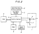
- FIG. 2 is a block diagram of the remote controller according to this embodiment.
- the numeral 2 indicates operating keys as it does in FIG. 4, and there are numbered operating keys [1] - [12] for the preset control signal group select setting operations to be described later, as well as a PW key.
- Numeral 3 indicates a key matrix encoder for outputting the information input by the user via the operating keys 2.
- Numeral 4 indicates a microcomputer-based control unit which selects and outputs the desired control signal according to the operation input information provided by the key matrix encoder 3.
- Numeral 5 indicates an ROM (Read Only Memory). Various formats and code systems are adopted by different makers for their various models of electronic equipment and this ROM therefore contains preset data which cover this large number of control signal groups. The user can then select one control signal group from the data by using the select setting operation.
- the control signal for the control signal group selected is then put into an RAM (Random Access Memory) 9.
- RAM Random Access Memory
- the control signal for the control signal group selected is read from the RAM and then outputted.
- control signal for the control signal group selected is not put into the RAM 9 but can instead be stored in an address in the ROM 5. It is also preferable if the RAM 9 used for storing back up data is a non-volatile type RAM.
- numeral 6 indicates an LED (light emitting diode) driven infrared output section for outputting infrared light
- numeral 7 indicates an LED driver.
- the control section 4 uses the on/off switching function of an LED driver 7 driving transistor to turn the infrared output section 6 on and off, which in turn outputs the control signal via infrared light.
- Numeral 8 represents a sound generator which is controlled by the control section 4 to produce sounds such as electronically produced sounds.
- the control preset groups are stored in the ROM 5 as information for the keys numbered [1] - [12] as well as information concerning multiple presses of these keys.
- the keys numbered [1] - [12] could represent the corporations A to L and then each additional pressing operation will represent each of the various codes that corporation has adopted for its various electronic equipments.
- key number 1 could correspond to the control signal group which the corporation A uses for its products, with the two types of formats and code systems used by the corporation then being brought forward by pressing the key once for code CA1 and twice for code CA2.
- the type of code which is most commonly adopted by that corporation will correspond to the first pressing of the key, with the second most commonly adopted corresponding to the second pressing of the key, and so on.
- the select setting operation is enabled by, for example, pressing the PW (power) key and a numbered key at the same time.
- the control section 4 goes from normal control signal output mode into preset select setting mode (F100) and the variables K1, K0 and t are set, with K1 and t being set to zero (F101, F102).
- the variable K1 will hold the ID (Identification Code to classify the keys [1] - [12]) of the numbered key which had been most recently pressed during the period of the preset select setting mode.
- the variable K0 is the key number ID for the key currently being pressed and the variable t represents the number of times the same key has been continued to be pressed.
- the control section 4 recognizes when the PW key is no longer being pressed and at this point will embark upon the enter operation. If the PW key is released without a numbered key having been pressed while it was held down, i.e. the variables K1 and t are zero, there will not have been any new select setting operation and the system will return to normal mode. The control signal group selected in the previous select setting will then be outputted for any subsequent key operations (F103 - F112-F115).
- the number of times the new key has been pressed is then determined in the following way.
- the next stage is to detect how many times the key has been pressed.
- the variable K1 0 (i.e. one press)
- the variable K1 is set to the ID of the currently inputted numbered key and the variable t is incremented.
- the step F109 then ensures that the variable t will display the number of times the same key has been pressed after subsequent pressings of the button.
- variable K1 is set to the value of the key number ID.
- the control signal group to be selected is then identified by using the information about the number of times the key has been pressed represented by the variable t to refer to the matrix shown in FIG. 3.
- the remote control signal is then set up in the RAM 9 so that the control output operations are carried out according to the control signal group selected (F113).
- a confirmation sound is then output from the sound generator 8 to confirm to the user that the control signal group select set up operation has been completed (F114) and the system returns to normal mode (F115).
- a numbered key is pressed more than the number of stored preset times, for example, in FIG. 3, if key number [1] is pressed three times or more, or key number [3] is pressed two times or more, the control signal group which is allotted to the highest number of allowed presses will be selected. It follows that if key number [1] is pressed three times or more then A corporations code CA2 will be selected and that if key number [3] is pressed a number of times then, as this key only has one kind of control signal group for its corresponding corporation, that signal group will be selected.
- the sound generator emit a warning noise when a key has been pressed the predetermined number of times.
- the select setting process involves designating control signal groups to the numbered keys and the multiple repetitive operations of the numbered keys. In this way, it is possible to store as presets a number of control signal groups which exceeds the number of actual numbered keys. A remote controller which is suitable for most of the models made by the majority of makers can therefore be attained. Having a numbered key for each corporation also means it is easy for the user to discriminate between the various makers and even if that maker has adopted a number of codes, it is possible to select the desired code in a simple manner by repeatedly pressing the corresponding key.
- control signal group with its format and control system preset within different positions in the matrix.
- a corporations code CA1 and J corporations code may be the same but they could still be recalled using different numbered keys so that the user does not get confused when carrying out the select set up operation.
- the select set up operation is not simply limited to the use of numbered keys as the operation keys. Also, the select set up process is not just limited to the process flow shown in FIG. 1.
- the operation keys in this embodiment correspond to corporations, but other variations are also possible.
- the operating keys could be made to correspond to various makers of electronic equipment such as televisions, video tape recorders (VTRs), and compact disc players, and the number of times the keys are pressed could then correspond to the various models produced by that particular maker.
- VTRs video tape recorders
- compact disc players the number of times the keys are pressed could then correspond to the various models produced by that particular maker.
Landscapes
- Physics & Mathematics (AREA)
- General Physics & Mathematics (AREA)
- Engineering & Computer Science (AREA)
- Computer Networks & Wireless Communication (AREA)
- Signal Processing (AREA)
- Selective Calling Equipment (AREA)
- Transmitters (AREA)
- Optical Communication System (AREA)
- Details Of Television Systems (AREA)
Claims (13)
- Verfahren zum selektiven Einstellen von Fernsteuersignalgruppen, welches folgende Schritte umfaßt:(a) Bestimmen (F100) eines voreingestellten Auswahleinstellmodus;(b) Unterscheiden (F103, F104, F105), ob es eine Eingabe gibt oder nicht, die von einer Betätigungseinrichtung ausgegeben wird;(c) Speichern (F106) eines Identifikationscodes (K0) gemäß der Eingabe von der Betätigungseinrichtung;(d) Unterscheiden (F107), ob der Identifikationscode (K0) mit einem vorher-festgelegten Identifikationscode (K1) übereinstimmt oder nicht, oder ob die Betätigungseinrichtung einmal oder mehrmals betätigt wurde; und, wenn der gegenwärtig bestimmte Identifikationscode (K0) mit dem festgelegten Identifikationscode (K1) übereinstimmt, Ändern des vorher-festgelegten Identifikationscodes (K1) auf den gegenwärtig bestimmten Identifikationscode und Erhöhen (F111) eines gespeicherten Zählwerts (t) mit der Häufigkeit, mit der die gleiche Betätigungseinrichtung betätigt wurde, um eins; und(e) Unterscheiden (F113) gemäß dem Eingangssignal von der Betätigungseinrichtung der ausgewählten Fernsteuersignalgruppe gemäß dem Identifikationscode und gemäß der Häufigkeit, mit der die Betätigungseinrichtung betätigt wurde, und Speichern von Fernsteuersignalen entsprechend der ausgewählten Fernsteuersignalgruppe in einer ersten Speichereinrichtung (9).
- Verfahren nach Anspruch 1, wobei die Identifikationscodes für die entsprechenden Hersteller von verschiedener Ausrüstung, die zu steuern sind, zugeteilt sind.
- Verfahren nach Anspruch 1, wobei die Identifkationscodes für die entsprechenden Kategorien von verschiedenen Ausrüstungen, die zu steuern sind, zugeteilt sind.
- Verfahren nach Anspruch 1, wobei die Identifikationscodes für die entsprechenden Fernsteuerformatsysteme von verschiedenen Ausrüstungen, die zu steuern sind, zugeteilt sind.
- Verfahren nach einem der vorhergehenden Ansprüche, welches weiter den Schritt zum Lesen von Fernsteuersignaldaten, die der ausgewählten Femsteuer-Signalgruppe entsprechen, aus einem zweiten Speicher (5) umfaßt.
- Verfahren nach einem der vorhergehenden Ansprüche, welches außerdem den Schritt umfaßt, einen gespeicherten Zählwert (t) auf "1" einzustellen, mit der Häufigkeit, mit der der vorliegende Identifikationscode von der Betätigungseinrichtung eingegeben wurde, wenn der gegenwärtige bestimmte Identifikationscode (K0) nicht mit dem vorher-bestimmten Identifikationscode (K1) übereinstimmt und wenn der vorher-festgelegte Identifikationscode nicht einen vorher-festgelegten Wert hat.
- Verfahren nach einem der vorhergehenden Ansprüche, welches weiter den Schritt umfaßt, ein hörbares Signal auszugeben (F114), um anzuzeigen, daß eine Fernsteuer-Signalgruppe ausgewählt wurde.
- Verfahren nach einem der vorhergehenden Ansprüche, bei dem, wenn aufeinanderfolgende Eingaben von der gleichen Betätigungseinrichtung mit einer Häufigkeit ausgegeben werden, die größer ist als die Anzahl der Fernsteuersignalgruppen, die dieser Betätigungseinrichtung zugeordnet sind, die Fernsteuersignalgruppe, die der höchsten Anzahl von Betätigungen dieser Betätigungseinrichtung entspricht, ausgewählt wird.
- Verfahren nach einem der vorhergehenden Ansprüche, welches außerdem den Schritt umfaßt, ein Warnsignal auszugeben, wenn die Häufigkeit, mit der eine Betätigungseinrichtung betätigt wird, größer ist als die Anzahl der Fernsteuersignalgruppen, die dieser zugeordnet ist.
- Verfahren nach Anspruch 9, bei dem das Warnsignal ein Warnton oder eine Anzeige ist.
- Verfahren nach einem der vorhergehenden Ansprüche, bei dem Fernsteuersignalgruppen der Anzahl von Aktivierungen einer Betätigungseinrichtung gemäß einer vorher-festgelegten Prioritätsordnung zugeordnet sind.
- Verfahren nach Anspruch 11, bei dem die Prioritätsordnung auf einen Marktanteil des Herstellers der Ausrüstung, die zu steuern ist, bezogen wird.
- Verfahren nach Anspruch 11, bei dem die Prioritätsordnung gemäß dem Verwendungsgrad des Formats der Fernsteuersignalgruppen ist.
Applications Claiming Priority (3)
| Application Number | Priority Date | Filing Date | Title |
|---|---|---|---|
| JP18284692 | 1992-06-18 | ||
| JP18284692A JP3214073B2 (ja) | 1992-06-18 | 1992-06-18 | リモートコマンダー、及びリモートコマンダー設定方法 |
| EP93304281A EP0577267A1 (de) | 1992-06-18 | 1993-06-02 | Fernbedienungsgerät und Methoden zur wahlweisen Einstellung von Fernbedienungssignalen |
Related Parent Applications (1)
| Application Number | Title | Priority Date | Filing Date |
|---|---|---|---|
| EP93304281A Division EP0577267A1 (de) | 1992-06-18 | 1993-06-02 | Fernbedienungsgerät und Methoden zur wahlweisen Einstellung von Fernbedienungssignalen |
Publications (3)
| Publication Number | Publication Date |
|---|---|
| EP0984560A2 EP0984560A2 (de) | 2000-03-08 |
| EP0984560A3 EP0984560A3 (de) | 2000-05-03 |
| EP0984560B1 true EP0984560B1 (de) | 2001-12-12 |
Family
ID=16125486
Family Applications (2)
| Application Number | Title | Priority Date | Filing Date |
|---|---|---|---|
| EP99121044A Expired - Lifetime EP0984560B1 (de) | 1992-06-18 | 1993-06-02 | Fernbedienungsgerät und Verfahren zur wahlweisen Einstellung von Fernbedienungssignalen |
| EP93304281A Ceased EP0577267A1 (de) | 1992-06-18 | 1993-06-02 | Fernbedienungsgerät und Methoden zur wahlweisen Einstellung von Fernbedienungssignalen |
Family Applications After (1)
| Application Number | Title | Priority Date | Filing Date |
|---|---|---|---|
| EP93304281A Ceased EP0577267A1 (de) | 1992-06-18 | 1993-06-02 | Fernbedienungsgerät und Methoden zur wahlweisen Einstellung von Fernbedienungssignalen |
Country Status (5)
| Country | Link |
|---|---|
| US (1) | US5485149A (de) |
| EP (2) | EP0984560B1 (de) |
| JP (1) | JP3214073B2 (de) |
| CA (1) | CA2097411C (de) |
| DE (1) | DE69331352T2 (de) |
Families Citing this family (23)
| Publication number | Priority date | Publication date | Assignee | Title |
|---|---|---|---|---|
| JPH077771A (ja) * | 1993-03-19 | 1995-01-10 | Sony Corp | リモートコマンダー |
| JPH0799690A (ja) * | 1993-09-28 | 1995-04-11 | Sony Corp | リモートコマンダー |
| US5969774A (en) * | 1994-11-17 | 1999-10-19 | Wininger; Dixon | Programmable remote control transmitter |
| AU1972297A (en) * | 1996-03-01 | 1997-09-16 | U.S. Electronics Components Corp. | Programmable universal remote control |
| US5614906A (en) * | 1996-04-23 | 1997-03-25 | Universal Electronics Inc. | Method for selecting a remote control command set |
| JP3783282B2 (ja) * | 1996-06-04 | 2006-06-07 | ソニー株式会社 | 通信制御方法、通信システムおよびそれに用いる電子機器 |
| US5819294A (en) * | 1997-08-06 | 1998-10-06 | Philips Electronics North America Corporation | Automatic configuration mechanism for universal remote |
| FR2768890B1 (fr) * | 1997-09-19 | 1999-12-03 | Charles Moransais | Telecommande adaptable pour appareils electriques disposant de plusieurs fonctions a commander |
| US5910784A (en) * | 1997-10-06 | 1999-06-08 | Lai; Jung-Hua | Control circuit of a remote controller |
| US6101401A (en) * | 1998-08-26 | 2000-08-08 | Dbtel Incorporated | Wireless telephone dialing method |
| US6282152B1 (en) | 1999-03-09 | 2001-08-28 | Timex Corporation | Learning security control device |
| KR100396547B1 (ko) * | 2000-12-27 | 2003-09-02 | 삼성전자주식회사 | 통합 입력기의 입력 코드 생성과 그 송수신 방법 및 장치 |
| JP5008463B2 (ja) * | 2007-06-05 | 2012-08-22 | スタンレー電気株式会社 | 調光方式および該調光方式を採用する照明装置 |
| US8130079B2 (en) * | 2007-08-15 | 2012-03-06 | At&T Intellectual Property I, L.P. | Methods, systems, and products for discovering electronic devices |
| JP4946986B2 (ja) * | 2008-06-30 | 2012-06-06 | 株式会社Jvcケンウッド | リモコン装置及びリモコン装置のプリセット方法 |
| KR101603340B1 (ko) * | 2009-07-24 | 2016-03-14 | 엘지전자 주식회사 | 제어 장치 및 그 동작 방법 |
| JP2012070035A (ja) * | 2010-09-21 | 2012-04-05 | Giga-Byte Technology Co Ltd | マクロ機能を有するキーボードとそれに関連したマクロ機能設定方法及びそのコンピュータプログラム製品 |
| EP2668546B1 (de) * | 2011-01-28 | 2017-07-26 | Gentex Corporation | Trainierbare drahtlose sende-/empfangsvorrichtung mit integrierter schnittstelle und gps-modulen |
| US20120317104A1 (en) * | 2011-06-13 | 2012-12-13 | Microsoft Corporation | Using Aggregate Location Metadata to Provide a Personalized Service |
| US8949053B2 (en) | 2011-07-29 | 2015-02-03 | Schneider Electric It Corporation | Systems and methods for current and voltage monitoring |
| US10372397B2 (en) | 2013-03-15 | 2019-08-06 | Infocus Corporation | Multimedia output and display device selection |
| US9210376B2 (en) | 2013-03-15 | 2015-12-08 | Infocus Corporation | Multimedia output and display device selection |
| JP6073735B2 (ja) * | 2013-04-12 | 2017-02-01 | 株式会社小糸製作所 | 車両用ランプ |
Citations (1)
| Publication number | Priority date | Publication date | Assignee | Title |
|---|---|---|---|---|
| EP0122548A2 (de) * | 1983-04-14 | 1984-10-24 | TELEFUNKEN Fernseh und Rundfunk GmbH | Fernbedienungsgerät zur drahtlosen Steuerung verschiedener Geräte |
Family Cites Families (9)
| Publication number | Priority date | Publication date | Assignee | Title |
|---|---|---|---|---|
| DE122548C (de) * | ||||
| US4703359A (en) * | 1985-05-30 | 1987-10-27 | Nap Consumer Electronics Corp. | Universal remote control unit with model identification capability |
| US4774511A (en) * | 1985-05-30 | 1988-09-27 | Nap Consumer Electronics Corp. | Universal remote control unit |
| US4694725A (en) * | 1985-09-03 | 1987-09-22 | Ncr Corporation | Sound generating system for a keyboard |
| EP0246472B1 (de) * | 1986-05-12 | 1991-08-07 | Siemens Aktiengesellschaft | Fernbedienungsstation |
| JPH01117595A (ja) * | 1987-10-30 | 1989-05-10 | Nec Home Electron Ltd | 遠隔制御装置の送信機 |
| DE68920458T2 (de) * | 1988-03-04 | 1995-08-24 | Philips Electronics Na | Universeller Fernsteuerungs-Sender mit vereinfachter Apparatidentifizierung. |
| JP2687454B2 (ja) * | 1988-06-28 | 1997-12-08 | ソニー株式会社 | 汎用コマンダ |
| US4866434A (en) * | 1988-12-22 | 1989-09-12 | Thomson Consumer Electronics, Inc. | Multi-brand universal remote control |
-
1992
- 1992-06-18 JP JP18284692A patent/JP3214073B2/ja not_active Expired - Fee Related
-
1993
- 1993-05-31 CA CA002097411A patent/CA2097411C/en not_active Expired - Fee Related
- 1993-06-02 EP EP99121044A patent/EP0984560B1/de not_active Expired - Lifetime
- 1993-06-02 EP EP93304281A patent/EP0577267A1/de not_active Ceased
- 1993-06-02 DE DE69331352T patent/DE69331352T2/de not_active Expired - Fee Related
- 1993-06-09 US US08/074,092 patent/US5485149A/en not_active Expired - Lifetime
Patent Citations (1)
| Publication number | Priority date | Publication date | Assignee | Title |
|---|---|---|---|---|
| EP0122548A2 (de) * | 1983-04-14 | 1984-10-24 | TELEFUNKEN Fernseh und Rundfunk GmbH | Fernbedienungsgerät zur drahtlosen Steuerung verschiedener Geräte |
Also Published As
| Publication number | Publication date |
|---|---|
| EP0984560A3 (de) | 2000-05-03 |
| CA2097411C (en) | 2003-04-22 |
| EP0577267A1 (de) | 1994-01-05 |
| US5485149A (en) | 1996-01-16 |
| JP3214073B2 (ja) | 2001-10-02 |
| EP0984560A2 (de) | 2000-03-08 |
| DE69331352D1 (de) | 2002-01-24 |
| DE69331352T2 (de) | 2002-08-22 |
| CA2097411A1 (en) | 1993-12-19 |
| JPH066876A (ja) | 1994-01-14 |
Similar Documents
| Publication | Publication Date | Title |
|---|---|---|
| EP0984560B1 (de) | Fernbedienungsgerät und Verfahren zur wahlweisen Einstellung von Fernbedienungssignalen | |
| KR100323967B1 (ko) | 프리셋데이타를선택및설정할수있는리모트커맨더 | |
| AU592991B2 (en) | Universal remote control unit | |
| US6236350B1 (en) | Universal remote control code identification system | |
| US5341166A (en) | System for controlling selected devices having unique sets of control codes | |
| US5228077A (en) | Remotely upgradable universal remote control | |
| US4999622A (en) | Remote commander having a ROM read-out pre-programmed codes therefrom | |
| EP0176965B1 (de) | Fernsteuergerät | |
| US6344817B1 (en) | Method of displaying manufacturer/model code and programmable universal remote control employing same | |
| US5227780A (en) | Apparatus with a portable UHF radio transmitter remote for controlling one or more of infrared controlled appliances | |
| EP1240716B1 (de) | Programmierung einer universellen fernsteuerung | |
| US5872562A (en) | Universal remote control transmitter with simplified device identification | |
| USRE39059E1 (en) | Computer programmable remote control | |
| US7116264B2 (en) | Programmable universal remote control unit | |
| EP1336167B1 (de) | System und verfahren zur erzeugung einer steuerungsvorrichtung | |
| US20030053002A1 (en) | Universal remote control unit | |
| US7154566B2 (en) | Programmable universal remote control unit and method of programming same | |
| WO1994014145A1 (en) | Favorite key macro command and chained macro command in a remote control | |
| EP0331257B1 (de) | Universeller Fernsteuerungs-Sender mit vereinfachter Apparatidentifizierung | |
| CN100416619C (zh) | 利用远程设备控制多个电器的方法和实现方法的远程设备 | |
| CN101193230A (zh) | 提供最佳用户界面的装置及方法 | |
| KR100491701B1 (ko) | 원격 제어 장치 및 상기 원격 제어 장치를 프로그래밍하기 위한 방법 | |
| US20040174288A1 (en) | Programmable universal control | |
| JPH06113365A (ja) | リモートコントロール方法及び装置 | |
| KR100839888B1 (ko) | 원격제어유닛 및 원격제어방법 |
Legal Events
| Date | Code | Title | Description |
|---|---|---|---|
| PUAI | Public reference made under article 153(3) epc to a published international application that has entered the european phase |
Free format text: ORIGINAL CODE: 0009012 |
|
| AC | Divisional application: reference to earlier application |
Ref document number: 577267 Country of ref document: EP |
|
| AK | Designated contracting states |
Kind code of ref document: A2 Designated state(s): DE FR GB |
|
| PUAL | Search report despatched |
Free format text: ORIGINAL CODE: 0009013 |
|
| AK | Designated contracting states |
Kind code of ref document: A3 Designated state(s): DE FR GB |
|
| 17P | Request for examination filed |
Effective date: 20000929 |
|
| AKX | Designation fees paid |
Free format text: DE FR GB |
|
| GRAG | Despatch of communication of intention to grant |
Free format text: ORIGINAL CODE: EPIDOS AGRA |
|
| 17Q | First examination report despatched |
Effective date: 20010404 |
|
| GRAG | Despatch of communication of intention to grant |
Free format text: ORIGINAL CODE: EPIDOS AGRA |
|
| GRAH | Despatch of communication of intention to grant a patent |
Free format text: ORIGINAL CODE: EPIDOS IGRA |
|
| GRAH | Despatch of communication of intention to grant a patent |
Free format text: ORIGINAL CODE: EPIDOS IGRA |
|
| GRAA | (expected) grant |
Free format text: ORIGINAL CODE: 0009210 |
|
| AC | Divisional application: reference to earlier application |
Ref document number: 577267 Country of ref document: EP |
|
| AK | Designated contracting states |
Kind code of ref document: B1 Designated state(s): DE FR GB |
|
| REG | Reference to a national code |
Ref country code: GB Ref legal event code: IF02 |
|
| REF | Corresponds to: |
Ref document number: 69331352 Country of ref document: DE Date of ref document: 20020124 |
|
| ET | Fr: translation filed | ||
| PLBE | No opposition filed within time limit |
Free format text: ORIGINAL CODE: 0009261 |
|
| STAA | Information on the status of an ep patent application or granted ep patent |
Free format text: STATUS: NO OPPOSITION FILED WITHIN TIME LIMIT |
|
| 26N | No opposition filed | ||
| PGFP | Annual fee paid to national office [announced via postgrant information from national office to epo] |
Ref country code: GB Payment date: 20030528 Year of fee payment: 11 |
|
| PGFP | Annual fee paid to national office [announced via postgrant information from national office to epo] |
Ref country code: FR Payment date: 20030610 Year of fee payment: 11 |
|
| PGFP | Annual fee paid to national office [announced via postgrant information from national office to epo] |
Ref country code: DE Payment date: 20030612 Year of fee payment: 11 |
|
| PG25 | Lapsed in a contracting state [announced via postgrant information from national office to epo] |
Ref country code: GB Free format text: LAPSE BECAUSE OF NON-PAYMENT OF DUE FEES Effective date: 20040602 |
|
| PG25 | Lapsed in a contracting state [announced via postgrant information from national office to epo] |
Ref country code: DE Free format text: LAPSE BECAUSE OF NON-PAYMENT OF DUE FEES Effective date: 20050101 |
|
| GBPC | Gb: european patent ceased through non-payment of renewal fee | ||
| PG25 | Lapsed in a contracting state [announced via postgrant information from national office to epo] |
Ref country code: FR Free format text: LAPSE BECAUSE OF NON-PAYMENT OF DUE FEES Effective date: 20050228 |
|
| REG | Reference to a national code |
Ref country code: FR Ref legal event code: ST |