EP0982867B1 - Unterputzmontage Modul mit einer schwenkbaren Antenne - Google Patents
Unterputzmontage Modul mit einer schwenkbaren Antenne Download PDFInfo
- Publication number
- EP0982867B1 EP0982867B1 EP99115813A EP99115813A EP0982867B1 EP 0982867 B1 EP0982867 B1 EP 0982867B1 EP 99115813 A EP99115813 A EP 99115813A EP 99115813 A EP99115813 A EP 99115813A EP 0982867 B1 EP0982867 B1 EP 0982867B1
- Authority
- EP
- European Patent Office
- Prior art keywords
- module
- antenna
- line
- flush
- figur
- Prior art date
- Legal status (The legal status is an assumption and is not a legal conclusion. Google has not performed a legal analysis and makes no representation as to the accuracy of the status listed.)
- Expired - Lifetime
Links
Images



Classifications
-
- H—ELECTRICITY
- H01—ELECTRIC ELEMENTS
- H01Q—ANTENNAS, i.e. RADIO AERIALS
- H01Q1/00—Details of, or arrangements associated with, antennas
- H01Q1/12—Supports; Mounting means
- H01Q1/22—Supports; Mounting means by structural association with other equipment or articles
-
- H—ELECTRICITY
- H01—ELECTRIC ELEMENTS
- H01Q—ANTENNAS, i.e. RADIO AERIALS
- H01Q1/00—Details of, or arrangements associated with, antennas
- H01Q1/12—Supports; Mounting means
- H01Q1/14—Supports; Mounting means for wire or other non-rigid radiating elements
-
- H—ELECTRICITY
- H01—ELECTRIC ELEMENTS
- H01Q—ANTENNAS, i.e. RADIO AERIALS
- H01Q1/00—Details of, or arrangements associated with, antennas
- H01Q1/36—Structural form of radiating elements, e.g. cone, spiral, umbrella; Particular materials used therewith
-
- H—ELECTRICITY
- H01—ELECTRIC ELEMENTS
- H01Q—ANTENNAS, i.e. RADIO AERIALS
- H01Q1/00—Details of, or arrangements associated with, antennas
- H01Q1/36—Structural form of radiating elements, e.g. cone, spiral, umbrella; Particular materials used therewith
- H01Q1/38—Structural form of radiating elements, e.g. cone, spiral, umbrella; Particular materials used therewith formed by a conductive layer on an insulating support
-
- H—ELECTRICITY
- H01—ELECTRIC ELEMENTS
- H01Q—ANTENNAS, i.e. RADIO AERIALS
- H01Q17/00—Devices for absorbing waves radiated from an antenna; Combinations of such devices with active antenna elements or systems
-
- H—ELECTRICITY
- H02—GENERATION; CONVERSION OR DISTRIBUTION OF ELECTRIC POWER
- H02J—ELECTRIC POWER NETWORKS; CIRCUIT ARRANGEMENTS OR SYSTEMS FOR SUPPLYING OR DISTRIBUTING ELECTRIC POWER; SYSTEMS FOR STORING ELECTRIC ENERGY
- H02J13/00—Circuit arrangements for providing remote monitoring or remote control of equipment in a power distribution network
Definitions
- the invention is based on the genus, as in independent claim 1 indicated.
- a burglar alarm system can be part of a home automation system be.
- a domotic system connects technical functions with applications in the household. For this include, for example, the safety technology, the Heating, ventilation and air conditioning control, the lighting and blind control as well as the load management.
- the Domotik With the Integration of home appliances and other technical devices in the house the Domotik is constantly extended. This includes the control of the stove, the washing machine, the Roller shutter control, the control of the garage door, the Remote inquiry, for example, of the gas or water meter etc.
- the domotic is as device and cross-application system, all in the House or individual components present in the home and Applications integrated into a system. The data exchange between sensors, actuators and a control panel doing so via the so-called European installation bus (EIB) of the European Installation Bus Association (EIBA), an organization in which the leading European Electrical installation companies have joined forces.
- EIB European installation bus
- EIBA European Installation Bus Association
- German Patent Application 198 15 986 is a Radio module for flush mounting, with a metallic, Flange-type support frame has been proposed, the at the flush mounting rests on a wall from the outside, which surrounds a mounting recess.
- the support frame at the same time element of a radio antenna of the module.
- In-wall socket mounted transceiver modules for electromagnetic waves have the systemic Disadvantage that either special design measures on Module necessary to make an antenna with good Take efficiency, or that only very small Designs are possible, if the complete module included the antenna in the - in the standard flush box to mounting - unit must be accommodated.
- the low mechanical dimensions cause in the preferably used for coming magnetic acting Antennas a bad efficiency.
- the design of all antenna means of the module can with simple means in their dimension to be enlarged to improve the efficiency.
- the assembly of the module with Antenna stays simple, and when installed in the Field of view, the antenna is not visible. This is a Advantage over known antenna designs, the visible out of a module.
- the antenna can be made robust so that it can withstand meet rough conditions of installation craft becomes. For the user of the installation technology is the Antenna invisible.
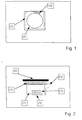
- Figure 1 shows a Top view without cover.
- FIG. A radio device 2 is connected via a line 3 with a Antenna 1 connected after the under-plaster installation of Module through a mounted on the plaster cover 4 is covered.
- the line 3 is not immediate connected to the radio device 2, but via a Resonant circuit 5, which with an antenna element 7 of Radio device 2 is coupled.
- the antenna element 7 acts as a magnetic antenna and is in the region of Floor of the module attached. With the magnetic Antenna element 7 alone, a module can be smaller Radio range can be realized.
- the one adapted to the working frequency of the module Resonant circuit 5 may be attached.
- This resonant circuit acts in the case of transmission operation together with the magnetic Antenna element 7 a transformer comparable and transmits much of the electromagnetic radiation on the over the line 3 ultimately with the Radio device 2 "connected" antenna 1 on.
- These Antenna 1 can be considered magnetic or electric Antenna be executed and has due to their clear larger mechanical dimensions a better one Efficiency as the antenna element 7. Is the module in Field of view attached, so the antenna 1 below be attached to the cover 4 made of plastic.
- the tuned resonant circuit 5 the line 3 (executed as so-called. Stripline) and the Antenna 1 advantageously on a flexible film. 8 (in particular made of plastic) be applied with Ladders is provided.
- the film 8 can with a protected adhesive film, whereby the Installation effort is reduced to a minimum.
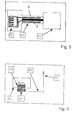
- FIG. 6 shows the block diagram of FIGS. 1 to 4.
- the designation Rx / Tx indicates that the magnetic antenna element 7 with a receiver (Rx) and / or transmitter (Tx) is connected.
- FIGS. 1 to 6 Designate reference numerals 9 and 10 in FIG Ground lines connected to earth potential. Of the High frequency connection for the radio device 2 is 12 designated.
Landscapes
- Support Of Aerials (AREA)
- Details Of Aerials (AREA)
- Selective Calling Equipment (AREA)
- Transceivers (AREA)
Description
- Figur 1:
- eine Aufsicht auf ein Modul für Unterputz-Montage nach der Erfindung,
- Figur 2:
- eine Seitenansicht desselben Moduls,
- Figur 3:
- eine Aufsicht auf das Modul bei abseits montierter Antenne,
- Figur 4:
- eine Seitenansicht des Moduls nach Figur 3,
- Figur 5:
- einige Einzelheiten zu den Figuren 3 und 4,
- Figur 6:
- ein Blockschaltbild zu den Figuren 1 bis 4,
- Figur 7:
- eine Aufsicht auf ein alternatives Modul für Unterputz-Montage nach der Erfindung,
- Figur 8:
- eine Seitenansicht des Moduls nach Figur 7,
- Figur 9:
- eine Aufsicht auf das alternative Modul bei abseits montierter Antenne,
- Figur 10:
- eine Seitenansicht des Moduls nach Figur 9,
- Figur 11:
- einige Einzelheiten zu den Figuren 9 und 10,
- Figur 12:
- ein Blockschaltbild zu den Figuren 9 und 10.
Claims (6)
- Modul mit einer Funkeinrichtung (2), für Unterputzmontage und mit einer Antenne (1), dadurch gekennzeichnet, dass die Antenne (1) zumindest über eine Leitung (3) mit der Funkeinrichtung (2) gekoppelt, die Antenne (1) auf einer flexiblen Folie (8) aufgebracht und gemeinsam mit der Leitung (3) so gestaltet ist, dass die Antenne (1) wahlweise unter einer Aufputz-Abdeckblende (4) des Moduls oder neben dem Modul unter Putz, einem Anstrich oder einer Tapete (6) Platz finden kann.
- Modul nach Anspruch 1, dadurch gekennzeichnet, dass zusätzlich ein magnetisches Antennenelement (7) vorgesehen ist, an welches die Leitung (3) magnetisch angekoppelt ist.
- Modul nach Anspruch 2, dadurch gekennzeichnet, dass die Leitung (3) über einen Schwingkreis (5) mit dem Antennenelement (7) gekoppelt ist.
- Modul nach Anspruch 1, dadurch gekennzeichnet, dass die Leitung (3) galvanisch mit der Funkeinrichtung (2) gekoppelt ist.
- Modul nach einem der vorangehenden Ansprüche, dadurch gekennzeichnet, dass die Leitung (3) von der Folie (8) getragen ist.
- Modul nach Anspruch 3 und 5, dadurch gekennzeichnet, dass die Folie (8) auch Teile des Schwingkreises (5) trägt.
Applications Claiming Priority (2)
| Application Number | Priority Date | Filing Date | Title |
|---|---|---|---|
| DE19838912A DE19838912A1 (de) | 1998-08-27 | 1998-08-27 | Modul |
| DE19838912 | 1998-08-27 |
Publications (3)
| Publication Number | Publication Date |
|---|---|
| EP0982867A2 EP0982867A2 (de) | 2000-03-01 |
| EP0982867A3 EP0982867A3 (de) | 2000-04-19 |
| EP0982867B1 true EP0982867B1 (de) | 2005-12-28 |
Family
ID=7878857
Family Applications (1)
| Application Number | Title | Priority Date | Filing Date |
|---|---|---|---|
| EP99115813A Expired - Lifetime EP0982867B1 (de) | 1998-08-27 | 1999-08-11 | Unterputzmontage Modul mit einer schwenkbaren Antenne |
Country Status (3)
| Country | Link |
|---|---|
| EP (1) | EP0982867B1 (de) |
| AT (1) | ATE314756T1 (de) |
| DE (2) | DE19838912A1 (de) |
Families Citing this family (5)
| Publication number | Priority date | Publication date | Assignee | Title |
|---|---|---|---|---|
| DE29913500U1 (de) | 1999-08-03 | 1999-12-16 | Siemens AG, 80333 München | Installationsgerät mit Funkantenne |
| DE10029486A1 (de) * | 2000-06-15 | 2001-12-20 | Rainer Toelle | Abdeckteil für Einbaudosen |
| DE20201325U1 (de) | 2002-01-16 | 2003-05-28 | Rademacher Geräte-Elektronik GmbH & Co. KG, 46414 Rhede | Elektronisches Steuergerät |
| DE102005025541A1 (de) * | 2005-06-03 | 2006-12-07 | Abb Patent Gmbh | Steckdose und Anzeigesystem eines Gebäudes mit mehreren Steckdosen |
| CN106760124B (zh) * | 2016-12-31 | 2022-12-27 | 天津力盾工程检测有限公司 | 一种便于施工的板体结构 |
Citations (2)
| Publication number | Priority date | Publication date | Assignee | Title |
|---|---|---|---|---|
| DE4411290A1 (de) * | 1994-03-31 | 1995-10-05 | Dorma Gmbh & Co Kg | Sensor |
| DE4422281C1 (de) * | 1994-06-25 | 1996-02-01 | Ziegler Horst | Datenfernerfassungssystem |
Family Cites Families (3)
| Publication number | Priority date | Publication date | Assignee | Title |
|---|---|---|---|---|
| US4464792A (en) * | 1981-09-16 | 1984-08-07 | A.R.F. Products, Inc. | Portable transmitter enclosure |
| JP3788829B2 (ja) * | 1996-09-04 | 2006-06-21 | 神保電器株式会社 | 室内遠隔制御システムに使用する受信側配線装置 |
| JPH1131201A (ja) * | 1997-07-10 | 1999-02-02 | Yamatake Honeywell Co Ltd | 非接触型識別装置の取付構造 |
-
1998
- 1998-08-27 DE DE19838912A patent/DE19838912A1/de not_active Withdrawn
-
1999
- 1999-08-11 AT AT99115813T patent/ATE314756T1/de not_active IP Right Cessation
- 1999-08-11 DE DE59912972T patent/DE59912972D1/de not_active Expired - Lifetime
- 1999-08-11 EP EP99115813A patent/EP0982867B1/de not_active Expired - Lifetime
Patent Citations (2)
| Publication number | Priority date | Publication date | Assignee | Title |
|---|---|---|---|---|
| DE4411290A1 (de) * | 1994-03-31 | 1995-10-05 | Dorma Gmbh & Co Kg | Sensor |
| DE4422281C1 (de) * | 1994-06-25 | 1996-02-01 | Ziegler Horst | Datenfernerfassungssystem |
Also Published As
| Publication number | Publication date |
|---|---|
| ATE314756T1 (de) | 2006-01-15 |
| EP0982867A2 (de) | 2000-03-01 |
| EP0982867A3 (de) | 2000-04-19 |
| DE59912972D1 (de) | 2006-02-02 |
| DE19838912A1 (de) | 2000-03-02 |
Similar Documents
| Publication | Publication Date | Title |
|---|---|---|
| EP0836732B1 (de) | Verbrauchserfassungssystem zur fernablesung | |
| EP1646156B1 (de) | Nachrichtenübertragungssystem unter Verwendung von elektrischem Nahfeld | |
| EP1879367A1 (de) | Funkkommunikationsanordnung | |
| EP1228578A1 (de) | Kommunikationssystem insbesondere für den indoor-bereich | |
| DE19602657A1 (de) | Antennenanordnung mit aktivem Übertrager | |
| CA2245671A1 (en) | Compact radio frequency transmitting and receiving antenna and control device employing same | |
| CA2173169A1 (en) | Electronic animal control system with masking signal generator | |
| DE4323144A1 (de) | Drahtloses Informationsübertragungssystem | |
| DE19654837A1 (de) | Bussystem für die Fernsteuerung, Programmierung und Überwachung von elektrischen Geräten in Versorgungsanlagen mit Verwendung der Niederspannungsleitungen für die Datenübertragung und Koppelmodul für den Anschluß der elektrischen Geräten an dieses Bussystem | |
| DE19838912A1 (de) | Modul | |
| DE19835252C2 (de) | Verfahren und System zur Übermittlung von Daten und/oder Steuerinformationen an eine Empfangsvorrichtung | |
| DE102019206334A1 (de) | Haushaltsgerät mit Energieübertragungseinrichtung | |
| EP0949708B1 (de) | Modul | |
| DE102006061705A1 (de) | Gebäudetechnisches Steuersystem | |
| DE4411290C2 (de) | Vorrichtung zur Aufnahme eines Sensors | |
| DE202017005523U1 (de) | Hauskommunikationsanlage | |
| DE102007059032A1 (de) | Vorrichtung zur automatisierten Erfassung und Weiterleitung der Zählerstände von Verbrauchzählern, insbesondere von Gas-, Strom- und Wasserzählern | |
| DE19521087B4 (de) | Fernsteuereinheit, die in Verbindung mit drahtlosen Signalen das Steuern einer Last ermöglicht | |
| AT502978B1 (de) | System zur steuerung elektrischer verbraucher der elektroinstallationstechnik | |
| DE4023457A1 (de) | Anordnung zur uebertragung von messwerten | |
| DE19954579C1 (de) | Vorrichtung zur Erfassung des Energieverbrauchs einer Heizungsanlage | |
| CN206370831U (zh) | 配电自动化无线公网信号增强装置和配电终端设备 | |
| CN215332099U (zh) | 一种指纹挂锁控电装置 | |
| DE19643293B4 (de) | Telefonanlage für schnurlose Telefonie | |
| JP2559226B2 (ja) | 建物開口部における電磁波遮蔽用の導電性接続金具 |
Legal Events
| Date | Code | Title | Description |
|---|---|---|---|
| PUAI | Public reference made under article 153(3) epc to a published international application that has entered the european phase |
Free format text: ORIGINAL CODE: 0009012 |
|
| AK | Designated contracting states |
Kind code of ref document: A2 Designated state(s): AT BE CH CY DE DK ES FI FR GB GR IE IT LI LU MC NL PT SE |
|
| AX | Request for extension of the european patent |
Free format text: AL;LT;LV;MK;RO;SI |
|
| PUAL | Search report despatched |
Free format text: ORIGINAL CODE: 0009013 |
|
| AK | Designated contracting states |
Kind code of ref document: A3 Designated state(s): AT BE CH CY DE DK ES FI FR GB GR IE IT LI LU MC NL PT SE |
|
| AX | Request for extension of the european patent |
Free format text: AL;LT;LV;MK;RO;SI |
|
| 17P | Request for examination filed |
Effective date: 20001019 |
|
| AKX | Designation fees paid |
Free format text: AT BE CH CY DE DK ES FI FR GB GR IE IT LI LU MC NL PT SE |
|
| 17Q | First examination report despatched |
Effective date: 20041227 |
|
| GRAP | Despatch of communication of intention to grant a patent |
Free format text: ORIGINAL CODE: EPIDOSNIGR1 |
|
| RTI1 | Title (correction) |
Free format text: FLUSH-MOUNTING MODULE WITH ROTATABLE ANTENNA |
|
| GRAS | Grant fee paid |
Free format text: ORIGINAL CODE: EPIDOSNIGR3 |
|
| GRAA | (expected) grant |
Free format text: ORIGINAL CODE: 0009210 |
|
| AK | Designated contracting states |
Kind code of ref document: B1 Designated state(s): AT BE CH CY DE DK ES FI FR GB GR IE IT LI LU MC NL PT SE |
|
| PG25 | Lapsed in a contracting state [announced via postgrant information from national office to epo] |
Ref country code: NL Free format text: LAPSE BECAUSE OF FAILURE TO SUBMIT A TRANSLATION OF THE DESCRIPTION OR TO PAY THE FEE WITHIN THE PRESCRIBED TIME-LIMIT Effective date: 20051228 Ref country code: IT Free format text: LAPSE BECAUSE OF FAILURE TO SUBMIT A TRANSLATION OF THE DESCRIPTION OR TO PAY THE FEE WITHIN THE PRESCRIBED TIME-LIMIT;WARNING: LAPSES OF ITALIAN PATENTS WITH EFFECTIVE DATE BEFORE 2007 MAY HAVE OCCURRED AT ANY TIME BEFORE 2007. THE CORRECT EFFECTIVE DATE MAY BE DIFFERENT FROM THE ONE RECORDED. Effective date: 20051228 Ref country code: IE Free format text: LAPSE BECAUSE OF FAILURE TO SUBMIT A TRANSLATION OF THE DESCRIPTION OR TO PAY THE FEE WITHIN THE PRESCRIBED TIME-LIMIT Effective date: 20051228 Ref country code: GB Free format text: LAPSE BECAUSE OF FAILURE TO SUBMIT A TRANSLATION OF THE DESCRIPTION OR TO PAY THE FEE WITHIN THE PRESCRIBED TIME-LIMIT Effective date: 20051228 Ref country code: FI Free format text: LAPSE BECAUSE OF FAILURE TO SUBMIT A TRANSLATION OF THE DESCRIPTION OR TO PAY THE FEE WITHIN THE PRESCRIBED TIME-LIMIT Effective date: 20051228 |
|
| REG | Reference to a national code |
Ref country code: GB Ref legal event code: FG4D Free format text: NOT ENGLISH |
|
| REG | Reference to a national code |
Ref country code: CH Ref legal event code: EP |
|
| REG | Reference to a national code |
Ref country code: IE Ref legal event code: FG4D Free format text: LANGUAGE OF EP DOCUMENT: GERMAN |
|
| REF | Corresponds to: |
Ref document number: 59912972 Country of ref document: DE Date of ref document: 20060202 Kind code of ref document: P |
|
| PG25 | Lapsed in a contracting state [announced via postgrant information from national office to epo] |
Ref country code: SE Free format text: LAPSE BECAUSE OF FAILURE TO SUBMIT A TRANSLATION OF THE DESCRIPTION OR TO PAY THE FEE WITHIN THE PRESCRIBED TIME-LIMIT Effective date: 20060328 Ref country code: GR Free format text: LAPSE BECAUSE OF FAILURE TO SUBMIT A TRANSLATION OF THE DESCRIPTION OR TO PAY THE FEE WITHIN THE PRESCRIBED TIME-LIMIT Effective date: 20060328 Ref country code: DK Free format text: LAPSE BECAUSE OF FAILURE TO SUBMIT A TRANSLATION OF THE DESCRIPTION OR TO PAY THE FEE WITHIN THE PRESCRIBED TIME-LIMIT Effective date: 20060328 |
|
| PG25 | Lapsed in a contracting state [announced via postgrant information from national office to epo] |
Ref country code: ES Free format text: LAPSE BECAUSE OF FAILURE TO SUBMIT A TRANSLATION OF THE DESCRIPTION OR TO PAY THE FEE WITHIN THE PRESCRIBED TIME-LIMIT Effective date: 20060408 |
|
| PG25 | Lapsed in a contracting state [announced via postgrant information from national office to epo] |
Ref country code: PT Free format text: LAPSE BECAUSE OF FAILURE TO SUBMIT A TRANSLATION OF THE DESCRIPTION OR TO PAY THE FEE WITHIN THE PRESCRIBED TIME-LIMIT Effective date: 20060529 |
|
| NLV1 | Nl: lapsed or annulled due to failure to fulfill the requirements of art. 29p and 29m of the patents act | ||
| GBV | Gb: ep patent (uk) treated as always having been void in accordance with gb section 77(7)/1977 [no translation filed] |
Effective date: 20051228 |
|
| REG | Reference to a national code |
Ref country code: IE Ref legal event code: FD4D |
|
| PG25 | Lapsed in a contracting state [announced via postgrant information from national office to epo] |
Ref country code: MC Free format text: LAPSE BECAUSE OF NON-PAYMENT OF DUE FEES Effective date: 20060831 Ref country code: LI Free format text: LAPSE BECAUSE OF NON-PAYMENT OF DUE FEES Effective date: 20060831 Ref country code: CH Free format text: LAPSE BECAUSE OF NON-PAYMENT OF DUE FEES Effective date: 20060831 Ref country code: BE Free format text: LAPSE BECAUSE OF NON-PAYMENT OF DUE FEES Effective date: 20060831 |
|
| PLBE | No opposition filed within time limit |
Free format text: ORIGINAL CODE: 0009261 |
|
| STAA | Information on the status of an ep patent application or granted ep patent |
Free format text: STATUS: NO OPPOSITION FILED WITHIN TIME LIMIT |
|
| 26N | No opposition filed |
Effective date: 20060929 |
|
| REG | Reference to a national code |
Ref country code: CH Ref legal event code: PL |
|
| PG25 | Lapsed in a contracting state [announced via postgrant information from national office to epo] |
Ref country code: AT Free format text: LAPSE BECAUSE OF NON-PAYMENT OF DUE FEES Effective date: 20060811 |
|
| BERE | Be: lapsed |
Owner name: ROBERT BOSCH G.M.B.H. Effective date: 20060831 |
|
| PG25 | Lapsed in a contracting state [announced via postgrant information from national office to epo] |
Ref country code: FR Free format text: LAPSE BECAUSE OF FAILURE TO SUBMIT A TRANSLATION OF THE DESCRIPTION OR TO PAY THE FEE WITHIN THE PRESCRIBED TIME-LIMIT Effective date: 20070216 |
|
| PG25 | Lapsed in a contracting state [announced via postgrant information from national office to epo] |
Ref country code: LU Free format text: LAPSE BECAUSE OF NON-PAYMENT OF DUE FEES Effective date: 20060811 |
|
| PG25 | Lapsed in a contracting state [announced via postgrant information from national office to epo] |
Ref country code: FR Free format text: LAPSE BECAUSE OF FAILURE TO SUBMIT A TRANSLATION OF THE DESCRIPTION OR TO PAY THE FEE WITHIN THE PRESCRIBED TIME-LIMIT Effective date: 20051228 Ref country code: CY Free format text: LAPSE BECAUSE OF FAILURE TO SUBMIT A TRANSLATION OF THE DESCRIPTION OR TO PAY THE FEE WITHIN THE PRESCRIBED TIME-LIMIT Effective date: 20051228 |
|
| PGFP | Annual fee paid to national office [announced via postgrant information from national office to epo] |
Ref country code: DE Payment date: 20091026 Year of fee payment: 11 |
|
| REG | Reference to a national code |
Ref country code: DE Ref legal event code: R119 Ref document number: 59912972 Country of ref document: DE Effective date: 20110301 |
|
| PG25 | Lapsed in a contracting state [announced via postgrant information from national office to epo] |
Ref country code: DE Free format text: LAPSE BECAUSE OF NON-PAYMENT OF DUE FEES Effective date: 20110301 |