EP0981916B1 - An enhanced radio telephone for use in internet telephony - Google Patents
An enhanced radio telephone for use in internet telephony Download PDFInfo
- Publication number
- EP0981916B1 EP0981916B1 EP98923248A EP98923248A EP0981916B1 EP 0981916 B1 EP0981916 B1 EP 0981916B1 EP 98923248 A EP98923248 A EP 98923248A EP 98923248 A EP98923248 A EP 98923248A EP 0981916 B1 EP0981916 B1 EP 0981916B1
- Authority
- EP
- European Patent Office
- Prior art keywords
- network
- signals
- far
- computer
- radio telephone
- Prior art date
- Legal status (The legal status is an assumption and is not a legal conclusion. Google has not performed a legal analysis and makes no representation as to the accuracy of the status listed.)
- Expired - Lifetime
Links
- 230000005236 sound signal Effects 0.000 claims description 31
- 238000000034 method Methods 0.000 claims description 25
- 238000004891 communication Methods 0.000 claims description 19
- 230000008878 coupling Effects 0.000 claims description 7
- 238000010168 coupling process Methods 0.000 claims description 7
- 238000005859 coupling reaction Methods 0.000 claims description 7
- 230000005540 biological transmission Effects 0.000 claims description 6
- 238000010586 diagram Methods 0.000 description 6
- 230000008901 benefit Effects 0.000 description 4
- 230000001413 cellular effect Effects 0.000 description 4
- 230000011664 signaling Effects 0.000 description 3
- 238000006243 chemical reaction Methods 0.000 description 2
- 238000005516 engineering process Methods 0.000 description 2
- 208000030979 Language Development disease Diseases 0.000 description 1
- 230000003213 activating effect Effects 0.000 description 1
- 238000002592 echocardiography Methods 0.000 description 1
- 230000008520 organization Effects 0.000 description 1
Images

Classifications
-
- H—ELECTRICITY
- H04—ELECTRIC COMMUNICATION TECHNIQUE
- H04M—TELEPHONIC COMMUNICATION
- H04M1/00—Substation equipment, e.g. for use by subscribers
- H04M1/72—Mobile telephones; Cordless telephones, i.e. devices for establishing wireless links to base stations without route selection
- H04M1/724—User interfaces specially adapted for cordless or mobile telephones
- H04M1/72403—User interfaces specially adapted for cordless or mobile telephones with means for local support of applications that increase the functionality
-
- H—ELECTRICITY
- H04—ELECTRIC COMMUNICATION TECHNIQUE
- H04M—TELEPHONIC COMMUNICATION
- H04M1/00—Substation equipment, e.g. for use by subscribers
- H04M1/253—Telephone sets using digital voice transmission
- H04M1/2535—Telephone sets using digital voice transmission adapted for voice communication over an Internet Protocol [IP] network
-
- Y—GENERAL TAGGING OF NEW TECHNOLOGICAL DEVELOPMENTS; GENERAL TAGGING OF CROSS-SECTIONAL TECHNOLOGIES SPANNING OVER SEVERAL SECTIONS OF THE IPC; TECHNICAL SUBJECTS COVERED BY FORMER USPC CROSS-REFERENCE ART COLLECTIONS [XRACs] AND DIGESTS
- Y02—TECHNOLOGIES OR APPLICATIONS FOR MITIGATION OR ADAPTATION AGAINST CLIMATE CHANGE
- Y02D—CLIMATE CHANGE MITIGATION TECHNOLOGIES IN INFORMATION AND COMMUNICATION TECHNOLOGIES [ICT], I.E. INFORMATION AND COMMUNICATION TECHNOLOGIES AIMING AT THE REDUCTION OF THEIR OWN ENERGY USE
- Y02D30/00—Reducing energy consumption in communication networks
- Y02D30/70—Reducing energy consumption in communication networks in wireless communication networks
Definitions
- the present invention relates to Internet telephony, and more particularly to an improved end-user interface for Internet-protocol (IP) telephone communication.
- IP Internet-protocol
- Internet telephony is an emerging competitor to conventional telephony as long distance calls are carried over the global Internet at relatively low cost. Additionally, although present Internet telephony systems provide comparably poor quality of service, future improvements will undoubtedly provide signal quality at least on the order of that provided by conventional systems.
- Available IP telephones consist primarily of a multimedia personal computer (PC) running a software telephony application which translates end-user sound signals into appropriately formatted digital signals for transfer over a computer network (e.g., the global Internet), and vice versa.
- a multimedia PC includes a sound card with a microphone and a speaker for speech input and output, and accesses the computer network through an appropriate network interface, such as a public switched telephone network (PSTN), a wireless network, or a public or private data network.
- PSTN public switched telephone network
- the software telephony application compresses and decompresses end-user speech signals in order to decrease bandwidth requirements for computer network transmissions.
- speech coding and decoding is typically carried out by a central processing unit (CPU) in the multimedia PC.
- CPU central processing unit
- the precise type of speech coding used depends upon the bit-rate and speech quality requirements for a given application.
- Compressed sound signals are transmitted over the computer network using an appropriate UDP/IP network protocol, as is well known in the art.
- the computer network protocol is conventionally administered by the software telephony application running on the multimedia PC.
- the IP telephone of today has several disadvantages as compared to a conventional telephone.
- common speech coding and decoding algorithms require high performance PCs including relatively fast CPUs.
- the conventional IP-telephone application requires extra sound equipment, such as a sound card and microphone, which is not often included in a standard consumer PC package.
- EP-A2-0 738 060 discloses a method for expanding the functionality of workstations connected to a LAN.
- the workstations are supplemented with a unit that is able to perform switching technology functions. Connections are established as needed for the exchange of information form cordless or wireless terminals.
- a terminal can be e.g. a telephone with digital circuit technology.
- Each terminal is connected to a network node or workstation, by either a wireless connection or a wired connection.
- the conventional IP telephone consists of a relatively high-end PC which is high-priced, power-hungry, and over-sized as compared to a conventional telephone. Additionally, the PC is normally switched of and requires a relatively long and inconvenient boot-up time. Furthermore, even a fully equipped PC dies not normally include a comfortable end-user telephone handset, and the relative distance between the PC microphone and PC speaker can cause disturbing echoes for system users. Thus, there is a real need for an improved IP telephone.
- the present invention fulfils the above described and other needs by providing a method for conducting telephony and an enhanced radio telephone which can be connected to a PC and used as a significantly improved IP telephone.
- the enhanced radio telephone can transmit and receive digitized and coded speech signals via an alternate external connection as well.
- a radio telephone that can selectively operate as a conventional radio telephone or as an improved IP telephone achieves the object of the invention.
- the radio telephone comprises a radio transceiver for transmitting coded near-end signals to, and receiving coded far-end signals from, a radio communication network.
- the radio telephone is characterised by a first external connection for transmitting coded near-end signals to, and receiving coded far-end signals from, a computer; and a digital interface for selectively transmitting coded near-end signals to one of said radio transceiver and said external connection and for selectively receiving coded far-end signals from one of said radio transceiver and said external connection.
- a method for conducting telephony comprising the steps of: setting a mode of operation of a radio telephone as one of a wireless-telephone mode and a IP-telephone mode; transmitting coded near-end signals to, and receiving coded far-end signals from a radio communication network via radio transceiver, when the mode of operation of the radio telephone is set to the mobile radio mode.
- the method is characterised by the further steps of: transmitting coded near-end signals to, and receiving coded far-end signals from, a computer via a first external connection, when the mode of operation of the radio telephone is set to a network protocol mode; and selectively transmitting coded near-end signals to one of said radio transceiver and said external connection and for selectively receiving coded far-end signals from one of said radio transceiver and said external connection.
- a radio telephone that can selectively operate as a conventional radio telephone or as an improved IP telephone achieves the object of the invention.
- the radio telephone comprises a microphone for receiving near-end sound and for providing corresponding near-end audio signals; a speech coder coupled to said microphone for coding near-end audio signals received from said microphone to provide coded near-end signals at an output of said speech coder; a speaker for receiving far-end audio signals and for broadcasting corresponding far-end sound to a near-end user of said radio telephone; a speech decoder coupled to said speaker for decoding coded far-end signals received at an input of said speech decoder to provide far-end audio signals to said speaker.
- the radio telephone is characterised by a radio transceiver for receiving coded far-end signals from, and transmitting coded near-end signals to, a radio communication network; an external connection for receiving network-formatted far-end signals from, and transmitting network-formatted near-end signals to, a computer network; a converter for receiving coded near-end signals and providing corresponding network-formatted near-end signals to said external connection and for receiving network-formatted far-end signals from said external connection and providing corresponding coded far-end signals; and a digital interface for selectively coupling the output of said speech coder and the input of said speech decoder to one of said radio transceiver and said converter
- the above object is achieved by a method for conducting telephony, wherein the radio telephone includes a radio transceiver for communicating with a radio communication network, comprising the steps of:
- the enhanced radio telephone includes an internal speech coder which is implemented for low power consumption and which allows the enhanced radio telephone to be used with a relatively low-performance PC for effective IP telephony.
- the enhanced radio telephone thereby provides a low cost IP telephone solution in which speech delay is reduced as compared to conventional IP telephone systems.
- the enhanced radio telephone handset is convenient for speech conversation and reduces the above described echo problems which are commonly associated with conventional IP telephones.
- the enhanced radio handset is connected via a cable to a serial or parallel port of a PC running a streamlined software telephony application.
- a wireless infrared (IR) or short range radio connection is used for communication between the enhanced radio telephone and the PC.
- Coded and compressed digital speech signals are passed back and forth between the enhanced radio telephone and the PC, and the PC performs conversions between the coded speech signals and an appropriate computer network protocol. Because the PC need not perform speech coding and decoding, the PC may be implemented, for example, as a low-end desk-top computer, a lap-top/notebook computer, or even a palm-top computer.
- a standard PC serial or parallel port connection is sufficient to carry digital speech and control signalling in both directions between the enhanced radio telephone and the PC.
- IP-telephone control is initiated from either the PC or the enhanced radio telephone.
- the enhanced radio telephone is switched between ordinary wireless (e.g., cellular) operation and IP-telephone operation either manually (e.g., via a pushbutton on the radio handset) or automatically from the PC (e.g., via an option in the telephony application running on the PC).
- a call can be initiated using either the PC software telephony application or a keypad on the enhanced radio telephone.
- the enhanced radio telephone is also used for wireless data communication in order to carry IP speech.
- coded speech is passed from the enhanced radio telephone to the PC where it is formatted according to an appropriate UDP/IP network protocol, and the resulting IP speech is passed back to the enhanced radio telephone for transmission to a computer network via a wireless network interface.
- IP data transfer is conducted using either a separate connection on the enhanced radio telephone or the same connection which is used to carry coded speech and control signalling.
- a PC serial port is sufficient to carry digital speech, control signalling and IP data.
- the present invention provides an improved IP telephone which is more convenient, economical and efficient as compared to conventional IP telephony systems.
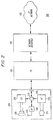
- FIG. 1 depicts a prior art IP telephony system 100.
- the conventional system 100 includes a high-performance PC 110 and a network interface 120.
- the high-performance PC 110 includes a speaker 105, a sound card 125, a microphone 115, a CPU 135, and an input/output port 145.
- an output of the microphone 115 is coupled to an input of the sound card 125
- an output of the sound card 125 is coupled to an input of the speaker 105.
- An input/output port of the sound card 125 is coupled to a first input/output port of the CPU 135, and a second input/output port of the CPU 135 is coupled to the PC input/output port 145.
- the PC input/output port 145 is in turn coupled to a first input/output port of the network interface 120, and a second input/output port of the network interface 120 is coupled to a network 130.
- the network 130 may be, for example, the global Internet or an Intranet operated by a public or private organization.
- IP Intranet-protocol
- a near-end user of the PC 110 initiates an IP telephone call, for example by activating a software telephony application on the PC 110.
- the near-end user speaks into the microphone 115, and the audio signal received by the microphone 115 is digitized within the sound card 125.
- the digitized signal which is output by the sound card 125 is passed to the CPU 135.
- the CPU 135, which is running the telephony application compresses and codes the digitized speech using an appropriate speech coding algorithm (e.g., GSM, D-AMPS, etc.) and converts the coded speech, using an appropriate UDP/IP network protocol, into a format which is appropriate for transmission via the network 130.
- the resulting IP data is transmitted by the CPU 135 via the PC input/output port 145 to the network interface 120, where it is routed to the network 130 and passed on to a far-end user.
- IP speech signals generated by the far-end user are received from the network 130 at the network interface 120 and passed to the PC 110 via the PC input/output port 145.
- the CPU 135 receives the IP-formatted far-end data and converts it to corresponding coded far-end speech signals.
- the coded far-end speech signals are decoded by the CPU 135 using an appropriate algorithm to produce digital sound data which is passed to the sound card 125.
- the sound card 125 converts the digital far-end sound data into a corresponding analog signal which is directed to the speaker 105 for presentation to the near-end user.
- the network interface 120 may connect to any one of a number of available systems in order to access the network 130.
- the network interface 120 may connect to a public switched telephone network (PSTN), a wireless radio system, or a public or private data network as appropriate.
- PSTN public switched telephone network
- the link between the PC 110 and the network interface 120 can utilize any appropriate digital protocol, depending upon the particular type of link used in a given application.
- the link is an analog PSTN
- the network interface 120 converts digital coded information received from the PC 110 into analog signals suitable for transmission over conventional telephone lines using a conventional modem.
- the link is a digital telephone network
- the network interface 120 converts digital information received from the PC 110 into a digital protocol associated with the telephone network (e.g., ISDN).
- ISDN digital protocol associated with the telephone network
- the network interface 120 When the link is a wireless radio system, the network interface 120 includes a suitable transceiver for modulating and demodulating signals transmitted to, and received from, the network interface 120, respectively.
- the network interface 120 converts digital coded information received from the PC 110 into a format which is appropriate for the public or private network.
- the network interface 120 can be integrated into the PC 110 or even the CPU 135.
- the present invention teaches that a radio telephone, ordinarily used exclusively for wireless radio (e.g., cellular) communication, can be enhanced to work in conjunction with a PC-based telephony application so that computationally intensive speech coding and decoding can be performed external to the PC and so that an effective IP telephone can be constructed economically without requiring a high-end computer.
- a radio telephone ordinarily used exclusively for wireless radio (e.g., cellular) communication
- a radio telephone ordinarily used exclusively for wireless radio (e.g., cellular) communication
- a PC-based telephony application so that computationally intensive speech coding and decoding can be performed external to the PC and so that an effective IP telephone can be constructed economically without requiring a high-end computer.
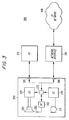
- FIG 2 is a conceptual diagram of an IP telephony system 200 constructed in accordance with the teachings of the present invention.
- the improved IP telephony system 200 includes an enhanced wireless telephone 250, a PC 210 and a network interface 120.
- the enhanced wireless telephone 250 includes a speaker 205 (e.g., an earphone in a wireless handset), a speech decompressor 225, an antenna 255, a radio frequency transceiver 265, a digital interface 275, an external connection 245, a speech compressor 235 and a microphone 215 (e.g., within a mouthpiece in a wireless handset).
- an output of the microphone 215 is coupled to an input of the speech compressor 235, and an output of the speech compressor 235 is coupled to an input of the digital interface 275. Additionally, an output of the digital interface 275 is coupled to an input of the speech decompressor 225, and an output of the speech decompressor 225 is coupled to an input of the speaker 205.
- the antenna 255 is bi-directionally coupled to the RF transceiver 265 which is in turn bi-directionally coupled to a first input/output port of the digital interface 275.
- a second input/output port of the digital interface 275 is coupled to the external connection 245, and the external connection 245 is in turn coupled to a first input/output port of the PC 210.
- a second input/output port of the PC 210 is coupled to a first input/output port of the network interface 120, and a second input/output port of the network interface 120 is coupled to a network 130 such as the global Internet or an Intranet.
- the digital interface 275 directs output from the speech coder 235 to the radio frequency transceiver 265, and directs output from the radio frequency transceiver 265 to the speech decoder 225, so that the enhanced radio telephone 250 operates as a conventional wireless telephone.
- speech signals from the near-end user received at the microphone 215 are compressed and coded by the speech coder 235 and transmitted by the radio frequency transceiver 265 to a wireless (e.g., cellular) system via the antenna 255.
- far-end radio signals received from the wireless system by the radio frequency transceiver 265 are decoded by the speech decoder 225 and presented to the near-end user via the speaker 205.
- the digital interface 275 directs output from the speech coder 235 to the external connection 245, and directs output from the external connection 245 to the speech decoder 225, so that the enhanced radio telephone 250 operates in conjunction with the PC 210 as an improved IP telephone.
- coded speech signals are passed from the speech coder 235 to the PC 210 where they are formatted by a software telephony application using an appropriate UDP/IP network protocol.
- the network-formatted signals are transmitted by the PC 210 to the network 130 via the network interface 120 as described above with reference to Figure 1.
- network-formatted far-end signals received at the PC 210 via the network interface 120 are converted by the PC telephony application into corresponding coded far-end speech signals.
- the coded far-end speech signals are passed to the speech decoder 225 where they are decoded and presented to the near-end user via the speaker 205.
- the network interface 120 may connect to any one of a number of available network links, including a PSTN, a wireless radio system, or a public or private data network.
- the network interface 120 can be integrated within the PC 210.
- the speech coder 235 and the speech decoder 225 respectively, code and decode speech during IP-telephone operation using the same algorithms (e.g., GSM, D-AMPS, etc.) used during radio-telephone operation.
- the speech coder 235 and the speech decoder 225 are constructed in accordance with the radio telephone art to operate at high speed using relatively little power. Because the burden of speech coding and decoding is removed from the telephony application running on the PC 210, the telephony application can be streamlined, and the CPU within the PC 210 need not be nearly as fast as that of the PC 110 of the system of Figure 1. Additionally, the PC 210 need not include a sound card, a microphone, or a speaker.
- the PC 210 can be implemented using a relatively inexpensive, relatively low-performance computer.
- the enhanced radio telephone 250 provides a convenient and comfortable handset for the near-end user and significantly reduces the echo problem associated with conventional IP telephones. For example, because the near-end user holds the handset to his or her ear, the echo path between the microphone and the speaker is largely blocked.
- the enhanced radio telephone 250 can provide echo canceling circuitry as is well known in the radio telephone art.
- connection 245 and the PC 210 are implemented using a standard serial or parallel PC cable connection.
- the connection can be established using well known IR or shortwave radio techniques.
- Coded speech and control information is exchanged between the enhanced radio telephone 250 and the PC 210 using handshaking techniques which are well known in the art.
- the enhanced radio telephone 250 and the PC 210 are programmed so that IP-telephone operation can be controlled from either the PC 210 or the enhanced radio telephone 250. Switching between IP-telephone operation and wireless-telephone operation can be initiated manually using a keypad on the enhanced radio telephone 250 or automatically via the telephony application running on the PC 210. Additionally, a user of the enhanced radio telephone 250 can initiate a call using either the enhanced radio telephone keypad or the telephony application on the PC.
- the embodiment of Figure 2 provides an improved IP telephone which is more convenient, economical and efficient than conventional IP telephones.
- FIG 3 is a conceptual diagram of an alternative IP telephony system 300 constructed in accordance with the teachings of the present invention.
- the IP telephony system 300 includes an enhanced wireless telephone 350, a PC 310 and a network interface 120.
- the enhanced wireless telephone 350 includes a speaker 205, a speech decompressor 225, an antenna 255, a radio frequency transceiver 265, a digital interface 275, first and second external connections 345, 346, a speech compressor 235 and a microphone 215.
- an output of the microphone 215 is coupled to an input of the speech compressor 235, and an output of the speech compressor 235 is coupled to an input of the digital interface 275. Additionally, an output of the digital interface 275 is coupled to an input of the speech decompressor 225, and an output of the speech decompressor 225 is coupled to an input of the speaker 205.
- the antenna 255 is bi-directionally coupled to the RF transceiver 265 which is in turn bi-directionally coupled to a first input/output port of the digital interface 275.
- a second input/output port of the digital interface 275 is coupled to each of the external connections 345, 346.
- the first external connection 345 is coupled to an input/output port of the PC 310, and the second external connection 346 is coupled to a first input/output port of the network interface 120.
- a second input/output port of the network interface 120 is coupled to a network 130 such as the global Internet or an Intranet.
- the digital interface 275 directs output from the speech coder 235 to the radio frequency transceiver 265, and directs output from the radio frequency transceiver 265 to the speech decoder 225, so that the enhanced radio telephone 250 operates as a conventional wireless telephone.
- the PC 310 is used to convert between coded speech data and network-formatted data, and the enhanced radio telephone 350 is used to exchange network-formatted data with the network 130 via the network interface 120.
- coded speech signals are passed from the speech coder 235 to the PC 310 where they are formatted by a software telephony application using an appropriate UDP/IP network protocol. Thereafter, the network-formatted signals are directed back from the PC 310 to the enhanced radio telephone 350 and transmitted to the network 130 via the network interface 120. Conversely, network-formatted far-end signals received at the enhanced radio telephone 350 via the network interface 120 are passed to the PC 310 and converted by the telephony application into corresponding coded far-end speech signals. The coded far-end speech signals are passed back to the enhanced radio telephone 350 and then to the speech decoder 225 where they are decoded and presented to the near-end user via the speaker 205.
- the network interface 120 may connect to any one of a number of available network links, including a PSTN, a wireless radio system, or a public or private data network.
- the network interface 120 may be integrated within the enhanced radio telephone 350.
- the link is a PSTN
- the network interface 120 may comprise a modem or an ISDN line.
- the link is a public or private data network
- the network interface 120 comprises an appropriate digital connection (e.g., an Ethernet connection).
- the link is a wireless radio system
- the network interface 120 comprises a suitable transceiver for modulating and demodulating network-formatted signals as necessary.
- the RF transceiver 265 can be adapted to provide appropriate wireless communication during both the wireless-telephone mode of operation and the IP-telephone mode of operation.
- the operating frequencies of the RF transceiver 265 can be tuned as necessary to communicate with different systems.
- the embodiment of Figure 3 provides advantages similar to those described above with respect to the embodiment of Figure 2. Additionally, because the task of communicating with the network 130 is shifted to the enhanced radio telephone 350, the PC 310 (and the telephony application running on the PC 310) can be streamlined still further. Thus, like the embodiment of Figure 2, the exemplary embodiment of Figure 3 provides an improved IP telephone which is more convenient, economical and efficient than conventional IP telephones.
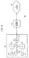
- FIG 4 is a conceptual diagram of another alternative IP telephony system 400 constructed in accordance with the teachings of the present invention.
- the IP telephony system 400 includes an enhanced wireless telephone 450 and a network interface 120.
- the enhanced wireless telephone 450 includes a speaker 205, a speech decompressor 225, an antenna 255, a radio frequency transceiver 265, a digital interface 275, a network converter 410, an external connection 445, a speech compressor 235 and a microphone 215.
- an output of the microphone 215 is coupled to an input of the speech compressor 235, and an output of the speech compressor 235 is coupled to an input of the digital interface 275. Additionally, an output of the digital interface 275 is coupled to an input of the speech decompressor 225, and an output of the speech decompressor 225 is coupled to an input of the speaker 205.
- the antenna 255 is bi-directionally coupled to the RF transceiver 265 which is in turn bi-directionally coupled to a first input/output port of the digital interface 275.
- a second input/output port of the digital interface 275 is coupled to a first input/output port of the network converter 410, and a second input/output port of the network converter 410 is coupled to the external connection 445. Additionally, the external connection 445 is coupled to a first input/output port of the network interface 120, and a second input/output port of the network interface 120 is coupled to a network 130 such as the global Internet or an Intranet.
- operation of the exemplary embodiment of Figure 4 is similar to operation of the embodiments of Figures 2 and 3.
- the digital interface 275 directs output from the speech coder 235 to the radio frequency transceiver 265, and directs output from the radio frequency transceiver 265 to the speech decoder 225, so that the enhanced radio telephone 450 operates as a conventional wireless telephone.
- the internal network converter 410 converts between coded speech data and network-formatted data, and therefore an external PC is not necessary.
- coded speech signals are passed from the speech coder 235 to the network converter 410 where they are formatted using an appropriate UDP/IP network protocol. Thereafter, the network-formatted signals are directed to the network 130 via the network interface 120. Conversely, network-formatted far-end signals received at the enhanced radio telephone 350 via the network interface 120 are converted by network converter 410 into corresponding coded far-end speech signals. The coded far-end speech signals are passed through the digital interface 275 to the speech decoder 225 where they are decoded and presented to the near-end user via the speaker 205.
- the network interface 120 may connect to any one of a number of available network links, including a PSTN, a wireless radio system, or a public or private data network.
- the network interface 120 may be integrated within the enhanced radio telephone 350.
- the link is a PSTN
- the network interface 120 may comprise a modem or an ISDN line.
- the link is a public or private data network
- the network interface 120 comprises an appropriate digital connection (e.g., an Ethernet connection).
- the link is a wireless radio system
- the network interface 120 comprises a suitable transceiver for modulating and demodulating network-formatted signals as necessary.
- the RF transceiver 265 can be adapted to provide appropriate wireless communication during both the wireless-telephone mode of operation and the IP-telephone mode of operation.
- the operating frequencies of the RF transceiver 265 can be tuned as necessary to communicate with different systems.
- the embodiment of Figure 4 provides advantages similar to those described above with respect to the embodiments of Figures 2 and 3. Additionally, because the task of converting between IP signals and coded speech signals is integrated into the enhanced radio telephone 450, the need for an external PC is eliminated. Thus, like the embodiments of Figures 2 and 3, the exemplary embodiment of Figure 4 provides an improved IP telephone which is more convenient, economical and efficient than conventional IP telephones. In practice, any one of the embodiments of Figures 2-4 can be utilized to advantage, depending upon the cost and performance requirements of a given application.
Landscapes
- Engineering & Computer Science (AREA)
- Signal Processing (AREA)
- Human Computer Interaction (AREA)
- Computer Networks & Wireless Communication (AREA)
- Telephonic Communication Services (AREA)
- Mobile Radio Communication Systems (AREA)
- Telephone Function (AREA)
- Data Exchanges In Wide-Area Networks (AREA)
Applications Claiming Priority (3)
| Application Number | Priority Date | Filing Date | Title |
|---|---|---|---|
| US08/857,543 US6157620A (en) | 1997-05-16 | 1997-05-16 | Enhanced radio telephone for use in internet telephony |
| US857543 | 1997-05-16 | ||
| PCT/SE1998/000828 WO1998052371A1 (en) | 1997-05-16 | 1998-05-05 | An enhanced radio telephone for use in internet telephony |
Publications (2)
| Publication Number | Publication Date |
|---|---|
| EP0981916A1 EP0981916A1 (en) | 2000-03-01 |
| EP0981916B1 true EP0981916B1 (en) | 2005-10-19 |
Family
ID=25326232
Family Applications (1)
| Application Number | Title | Priority Date | Filing Date |
|---|---|---|---|
| EP98923248A Expired - Lifetime EP0981916B1 (en) | 1997-05-16 | 1998-05-05 | An enhanced radio telephone for use in internet telephony |
Country Status (12)
| Country | Link |
|---|---|
| US (1) | US6157620A (enExample) |
| EP (1) | EP0981916B1 (enExample) |
| JP (1) | JP4003839B2 (enExample) |
| KR (1) | KR100490275B1 (enExample) |
| CN (1) | CN1115917C (enExample) |
| AU (1) | AU743238B2 (enExample) |
| BR (1) | BR9809830B1 (enExample) |
| DE (1) | DE69831942T2 (enExample) |
| EE (1) | EE9900526A (enExample) |
| MY (1) | MY120322A (enExample) |
| PL (1) | PL192563B1 (enExample) |
| WO (1) | WO1998052371A1 (enExample) |
Families Citing this family (41)
| Publication number | Priority date | Publication date | Assignee | Title |
|---|---|---|---|---|
| US20070123251A1 (en) * | 1996-10-23 | 2007-05-31 | Riparius Ventures, Llc | Remote internet telephony device |
| FI103463B1 (fi) * | 1997-04-23 | 1999-06-30 | Nokia Mobile Phones Ltd | Tietokone ja menetelmä tietokoneen käyttämiseksi |
| JP3584278B2 (ja) * | 1997-06-06 | 2004-11-04 | サクサ株式会社 | 送受話用ハンドセット付きパーソナルコンピュータ |
| EP0954151B1 (de) * | 1998-05-02 | 2006-08-02 | Micronas GmbH | Lokales Kommunikationsgerät |
| US6549534B1 (en) * | 1998-09-14 | 2003-04-15 | Siemens Information & Communication Networks, Inc. | Apparatus and method for accessing wireless trunks on a communications network |
| US6993004B2 (en) * | 1998-10-29 | 2006-01-31 | Sound Starts, Inc. | Method and apparatus for practicing IP telephony from an Internet-capable radio |
| US6314094B1 (en) * | 1998-10-29 | 2001-11-06 | Central Coast Patent Agency Inc | Mobile wireless internet portable radio |
| US6700901B1 (en) * | 1998-11-09 | 2004-03-02 | Siemens Information & Communication Networks, Inc. | System and method for digital telephones on H.323 networks |
| US6845370B2 (en) | 1998-11-12 | 2005-01-18 | Accenture Llp | Advanced information gathering for targeted activities |
| US6134548A (en) * | 1998-11-19 | 2000-10-17 | Ac Properties B.V. | System, method and article of manufacture for advanced mobile bargain shopping |
| US6292566B1 (en) * | 1998-11-30 | 2001-09-18 | Qwest Communications International Inc. | Telephone and associated method for routing a call |
| US6356905B1 (en) | 1999-03-05 | 2002-03-12 | Accenture Llp | System, method and article of manufacture for mobile communication utilizing an interface support framework |
| US6199099B1 (en) | 1999-03-05 | 2001-03-06 | Ac Properties B.V. | System, method and article of manufacture for a mobile communication network utilizing a distributed communication network |
| US6401085B1 (en) | 1999-03-05 | 2002-06-04 | Accenture Llp | Mobile communication and computing system and method |
| GB9927283D0 (en) * | 1999-11-19 | 2000-01-12 | Pace Micro Tech Plc | Data receiver apparatus and telecommunications system |
| DE10035216A1 (de) * | 2000-02-22 | 2001-08-30 | Thomas Steinig | Adapter zur Verbindung von Telekommunikation-Endgeräten wie Telefongerät/Faxgerät mit einem Computer |
| US7301952B2 (en) * | 2000-04-06 | 2007-11-27 | The Distribution Systems Research Institute | Terminal-to-terminal communication connection control method using IP transfer network |
| US20010040960A1 (en) * | 2000-05-01 | 2001-11-15 | Eitan Hamami | Method, system and device for using a regular telephone as a computer audio input/output device |
| US6603965B1 (en) * | 2000-05-11 | 2003-08-05 | International Business Machines Corporation | Pervasive voice handset system |
| KR100686086B1 (ko) * | 2000-06-21 | 2007-02-23 | 엘지전자 주식회사 | 휴대용 무선 단말을 이용한 인터넷 전화 시스템 및 그 방법 |
| US20020019782A1 (en) * | 2000-08-04 | 2002-02-14 | Arie Hershtik | Shopping method |
| HK1030726A2 (en) * | 2000-09-25 | 2001-05-04 | 新科技工程有限公司 | Internet phone |
| TW511826U (en) * | 2001-01-20 | 2002-11-21 | Wang-You Yang | Wireless network phone device |
| US20020127969A1 (en) * | 2001-03-12 | 2002-09-12 | Meade William Kendall | Wireless network storage device and method |
| DE10153747A1 (de) | 2001-10-31 | 2003-05-28 | Siemens Ag | Mobiles Endgerät sowie Kommunikationssystem mit integriertem mobilen Endgerät |
| KR100417818B1 (ko) * | 2001-11-13 | 2004-02-05 | 엘지전자 주식회사 | 휴대단말기용 인터넷 통신장치 및 그 운용방법 |
| EP1317118A1 (en) * | 2001-12-03 | 2003-06-04 | Alcatel | A telephone installation designed to operate over a local area network |
| US7418255B2 (en) | 2002-02-21 | 2008-08-26 | Bloomberg Finance L.P. | Computer terminals biometrically enabled for network functions and voice communication |
| US7349689B2 (en) * | 2003-07-01 | 2008-03-25 | Microsoft Corporation | Communications device processor peripheral |
| CN1555185B (zh) * | 2003-12-25 | 2010-04-28 | 海信集团有限公司 | Ip手机 |
| JP4446768B2 (ja) * | 2004-03-12 | 2010-04-07 | 三洋電機株式会社 | Ip電話機 |
| IL165099A0 (en) * | 2004-11-08 | 2005-12-18 | Compearls Ltd | Apparatus and system for communication in a community |
| US7626966B1 (en) | 2005-01-06 | 2009-12-01 | Idealab | Ad hoc wireless communication system |
| JP4639854B2 (ja) * | 2005-03-03 | 2011-02-23 | 株式会社日立製作所 | データ・音声送受信用無線lanカード |
| SE0501067L (sv) * | 2005-05-09 | 2006-11-10 | Ip Drum Holding Sa | Datortelefoni för mobiltelefoner |
| JP4774831B2 (ja) | 2005-06-30 | 2011-09-14 | 沖電気工業株式会社 | 音声処理周辺装置及びip電話システム |
| JP4156615B2 (ja) * | 2005-08-22 | 2008-09-24 | ソニー・エリクソン・モバイルコミュニケーションズ株式会社 | 携帯電話機、通信端末、通話方法及び通話プログラム |
| WO2008015054A1 (de) * | 2006-07-31 | 2008-02-07 | Siemens Aktiengesellschaft | Maschine, insbesondere werkzeug- oder produktionsmaschine, sowie system mit einer ip-telefonieeinheit |
| CN101193110A (zh) * | 2006-11-28 | 2008-06-04 | 中兴通讯股份有限公司 | 一种基于无线通讯终端的计算机语音通讯的实现方法 |
| CN101510904A (zh) * | 2008-12-22 | 2009-08-19 | 上海闻泰电子科技有限公司 | 一种手机扩音器及其实现方法 |
| CN102957818A (zh) * | 2011-08-31 | 2013-03-06 | 东讯股份有限公司 | 令未注册终端机拨打网络电话的桥接方法 |
Family Cites Families (8)
| Publication number | Priority date | Publication date | Assignee | Title |
|---|---|---|---|---|
| US5008927A (en) * | 1988-05-05 | 1991-04-16 | Transaction Technology, Inc. | Computer and telephone apparatus with user friendly computer interface integrity features |
| US5249218A (en) * | 1992-04-06 | 1993-09-28 | Spectrum Information Technologies, Inc. | Programmable universal interface system |
| WO1995022183A1 (en) * | 1994-02-10 | 1995-08-17 | Elonex Technologies, Inc. | Smart phone |
| US5553063A (en) * | 1994-09-12 | 1996-09-03 | Dickson; William D. | Voice over data communication system |
| CA2139081C (en) * | 1994-12-23 | 1999-02-02 | Alastair Gordon | Unified messaging system and method |
| DE19514043A1 (de) * | 1995-04-13 | 1996-10-17 | Sel Alcatel Ag | Lokales Netz für den Einsatz in der Bürokommunikation und Schaltungsanordnung dafür |
| GB2301987B (en) * | 1995-06-05 | 2000-01-12 | Nokia Mobile Phones Ltd | Radio telephone text transmission system |
| US6859525B1 (en) * | 1996-10-23 | 2005-02-22 | Riparius Ventures, Llc | Internet telephony device |
-
1997
- 1997-05-16 US US08/857,543 patent/US6157620A/en not_active Expired - Lifetime
-
1998
- 1998-05-05 BR BRPI9809830-6A patent/BR9809830B1/pt active IP Right Grant
- 1998-05-05 EP EP98923248A patent/EP0981916B1/en not_active Expired - Lifetime
- 1998-05-05 AU AU75583/98A patent/AU743238B2/en not_active Expired
- 1998-05-05 EE EEP199900526A patent/EE9900526A/xx unknown
- 1998-05-05 WO PCT/SE1998/000828 patent/WO1998052371A1/en not_active Ceased
- 1998-05-05 DE DE69831942T patent/DE69831942T2/de not_active Expired - Lifetime
- 1998-05-05 JP JP54912098A patent/JP4003839B2/ja not_active Expired - Lifetime
- 1998-05-05 PL PL336855A patent/PL192563B1/pl unknown
- 1998-05-05 CN CN98807179A patent/CN1115917C/zh not_active Expired - Lifetime
- 1998-05-05 KR KR10-1999-7010578A patent/KR100490275B1/ko not_active Expired - Lifetime
- 1998-05-07 MY MYPI98002041A patent/MY120322A/en unknown
Also Published As
| Publication number | Publication date |
|---|---|
| PL192563B1 (pl) | 2006-11-30 |
| CN1263676A (zh) | 2000-08-16 |
| EE9900526A (et) | 2000-06-15 |
| JP4003839B2 (ja) | 2007-11-07 |
| DE69831942T2 (de) | 2006-05-24 |
| US6157620A (en) | 2000-12-05 |
| AU743238B2 (en) | 2002-01-24 |
| CN1115917C (zh) | 2003-07-23 |
| BR9809830A (pt) | 2000-06-20 |
| AU7558398A (en) | 1998-12-08 |
| DE69831942D1 (de) | 2006-03-02 |
| KR20010012618A (ko) | 2001-02-26 |
| PL336855A1 (en) | 2000-07-17 |
| BR9809830B1 (pt) | 2013-02-05 |
| JP2001526858A (ja) | 2001-12-18 |
| MY120322A (en) | 2005-10-31 |
| WO1998052371A1 (en) | 1998-11-19 |
| EP0981916A1 (en) | 2000-03-01 |
| HK1030127A1 (en) | 2001-04-20 |
| KR100490275B1 (ko) | 2005-05-17 |
Similar Documents
| Publication | Publication Date | Title |
|---|---|---|
| EP0981916B1 (en) | An enhanced radio telephone for use in internet telephony | |
| US5956651A (en) | Cellular telephone interface system for AMPS and CDMA data services | |
| US7218900B2 (en) | Radio transmitter and receiver | |
| US7221662B2 (en) | Tone detection elimination | |
| US5848133A (en) | Information processing apparatus having speaker phone function | |
| US6584510B2 (en) | Computer and a method of operating a computer | |
| US7054280B2 (en) | Voice communication between a portable communication apparatus and an external terminal | |
| US6621802B1 (en) | Method and apparatus for substantially simultaneous audio and data communication over a wireless link | |
| KR20010029404A (ko) | 무선 데이터 통신을 위한 카드 장치 및 무선 통신이 가능한 장치 | |
| US5257410A (en) | Communication device with ISDN interface | |
| HK1030127B (en) | An enhanced radio telephone for use in internet telephony and method for conducting telephony | |
| CN1265612C (zh) | 经无线接口的数据传输方法及其系统 | |
| KR100374839B1 (ko) | 아이피 게이트웨이 및 그의 음성 데이터 처리방법 | |
| KR100276700B1 (ko) | 일반공중전화망용디지털음성전용전화기및이를이용한전화접속방법 | |
| TH21369B (th) | เครื่องโทรศัพท์วิทยุที่ได้รับการปรับปรุงสำหรับใช้ในโทรศัพท์ทางอินเตอร์เน็ต | |
| TH32057A (th) | เครื่องโทรศัพท์วิทยุที่ได้รับการปรับปรุงสำหรับใช้ในโทรศัพท์ทางอินเตอร์เน็ต | |
| JPS58151726A (ja) | 衛星回線による音声伝送方式 | |
| KR19980046181U (ko) | 전화 및 컴퓨터 통신장치 | |
| JPH08317077A (ja) | 携帯電話有線接続装置 | |
| JP2002027543A (ja) | デジタルデータ通信方法及びデジタルデータ通信装置 |
Legal Events
| Date | Code | Title | Description |
|---|---|---|---|
| PUAI | Public reference made under article 153(3) epc to a published international application that has entered the european phase |
Free format text: ORIGINAL CODE: 0009012 |
|
| 17P | Request for examination filed |
Effective date: 19991028 |
|
| AK | Designated contracting states |
Kind code of ref document: A1 Designated state(s): BE DE ES FI FR GB GR IT SE |
|
| 17Q | First examination report despatched |
Effective date: 20040112 |
|
| RAP1 | Party data changed (applicant data changed or rights of an application transferred) |
Owner name: TELEFONAKTIEBOLAGET LM ERICSSON (PUBL) |
|
| GRAP | Despatch of communication of intention to grant a patent |
Free format text: ORIGINAL CODE: EPIDOSNIGR1 |
|
| GRAS | Grant fee paid |
Free format text: ORIGINAL CODE: EPIDOSNIGR3 |
|
| GRAA | (expected) grant |
Free format text: ORIGINAL CODE: 0009210 |
|
| AK | Designated contracting states |
Kind code of ref document: B1 Designated state(s): BE DE ES FI FR GB GR IT SE |
|
| PG25 | Lapsed in a contracting state [announced via postgrant information from national office to epo] |
Ref country code: IT Free format text: LAPSE BECAUSE OF FAILURE TO SUBMIT A TRANSLATION OF THE DESCRIPTION OR TO PAY THE FEE WITHIN THE PRESCRIBED TIME-LIMIT;WARNING: LAPSES OF ITALIAN PATENTS WITH EFFECTIVE DATE BEFORE 2007 MAY HAVE OCCURRED AT ANY TIME BEFORE 2007. THE CORRECT EFFECTIVE DATE MAY BE DIFFERENT FROM THE ONE RECORDED. Effective date: 20051019 Ref country code: FI Free format text: LAPSE BECAUSE OF FAILURE TO SUBMIT A TRANSLATION OF THE DESCRIPTION OR TO PAY THE FEE WITHIN THE PRESCRIBED TIME-LIMIT Effective date: 20051019 Ref country code: BE Free format text: LAPSE BECAUSE OF FAILURE TO SUBMIT A TRANSLATION OF THE DESCRIPTION OR TO PAY THE FEE WITHIN THE PRESCRIBED TIME-LIMIT Effective date: 20051019 |
|
| REG | Reference to a national code |
Ref country code: GB Ref legal event code: FG4D |
|
| PG25 | Lapsed in a contracting state [announced via postgrant information from national office to epo] |
Ref country code: SE Free format text: LAPSE BECAUSE OF FAILURE TO SUBMIT A TRANSLATION OF THE DESCRIPTION OR TO PAY THE FEE WITHIN THE PRESCRIBED TIME-LIMIT Effective date: 20060119 Ref country code: GR Free format text: LAPSE BECAUSE OF FAILURE TO SUBMIT A TRANSLATION OF THE DESCRIPTION OR TO PAY THE FEE WITHIN THE PRESCRIBED TIME-LIMIT Effective date: 20060119 |
|
| PG25 | Lapsed in a contracting state [announced via postgrant information from national office to epo] |
Ref country code: ES Free format text: LAPSE BECAUSE OF FAILURE TO SUBMIT A TRANSLATION OF THE DESCRIPTION OR TO PAY THE FEE WITHIN THE PRESCRIBED TIME-LIMIT Effective date: 20060130 |
|
| REF | Corresponds to: |
Ref document number: 69831942 Country of ref document: DE Date of ref document: 20060302 Kind code of ref document: P |
|
| ET | Fr: translation filed | ||
| PLBE | No opposition filed within time limit |
Free format text: ORIGINAL CODE: 0009261 |
|
| STAA | Information on the status of an ep patent application or granted ep patent |
Free format text: STATUS: NO OPPOSITION FILED WITHIN TIME LIMIT |
|
| 26N | No opposition filed |
Effective date: 20060720 |
|
| REG | Reference to a national code |
Ref country code: FR Ref legal event code: PLFP Year of fee payment: 19 |
|
| REG | Reference to a national code |
Ref country code: FR Ref legal event code: PLFP Year of fee payment: 20 |
|
| PGFP | Annual fee paid to national office [announced via postgrant information from national office to epo] |
Ref country code: GB Payment date: 20170530 Year of fee payment: 20 Ref country code: DE Payment date: 20170530 Year of fee payment: 20 Ref country code: FR Payment date: 20170525 Year of fee payment: 20 |
|
| REG | Reference to a national code |
Ref country code: DE Ref legal event code: R071 Ref document number: 69831942 Country of ref document: DE |
|
| REG | Reference to a national code |
Ref country code: GB Ref legal event code: PE20 Expiry date: 20180504 |
|
| PG25 | Lapsed in a contracting state [announced via postgrant information from national office to epo] |
Ref country code: GB Free format text: LAPSE BECAUSE OF EXPIRATION OF PROTECTION Effective date: 20180504 |