EP0980698B1 - Kontrolleinrichtung für Lösung von Problemen - Google Patents
Kontrolleinrichtung für Lösung von Problemen Download PDFInfo
- Publication number
- EP0980698B1 EP0980698B1 EP99115726A EP99115726A EP0980698B1 EP 0980698 B1 EP0980698 B1 EP 0980698B1 EP 99115726 A EP99115726 A EP 99115726A EP 99115726 A EP99115726 A EP 99115726A EP 0980698 B1 EP0980698 B1 EP 0980698B1
- Authority
- EP
- European Patent Office
- Prior art keywords
- task
- arrangement
- accordance
- indicate
- room
- Prior art date
- Legal status (The legal status is an assumption and is not a legal conclusion. Google has not performed a legal analysis and makes no representation as to the accuracy of the status listed.)
- Expired - Lifetime
Links
Images





Classifications
-
- A—HUMAN NECESSITIES
- A63—SPORTS; GAMES; AMUSEMENTS
- A63G—MERRY-GO-ROUNDS; SWINGS; ROCKING-HORSES; CHUTES; SWITCHBACKS; SIMILAR DEVICES FOR PUBLIC AMUSEMENT
- A63G33/00—Devices allowing competitions between several persons, not otherwise provided for
-
- A—HUMAN NECESSITIES
- A63—SPORTS; GAMES; AMUSEMENTS
- A63F—CARD, BOARD, OR ROULETTE GAMES; INDOOR GAMES USING SMALL MOVING PLAYING BODIES; VIDEO GAMES; GAMES NOT OTHERWISE PROVIDED FOR
- A63F2250/00—Miscellaneous game characteristics
- A63F2250/24—Miscellaneous game characteristics with a lock, e.g. for a puzzle
Definitions
- the present invention relates to an arrangement in a building in which a number of separate locked rooms is arranged as problem-solving areas, inside which means are arranged for persons to attempt through skill and ability to solve various tasks, which are unfamiliar to the contestant on the circuit in which a number of rooms with doors fitted with locks is present.
- the principal object of the present invention is thus, in the first instance, to attempt to solve the aforementioned problems by simple but efficiently functioning means.
- An even better comparison is to compare known variants of an actual adventure data game and the present variant with an actual mystery adventure date game, for example Myst'.
- a central feature of the present variant is that tasks in rooms must be solved without any instructions and without knowing in advance what one is expected to do, and that one must move forward by trial and error, starting again from the beginning most of the time.
- the aforementioned control device comprises at least one of the following automatically acting control devices; an inductive sensor 4, a capacitive sensor 5, a magnetic control 6, a light relay 7, a movement detector 8 and a photocell 9.
- the aforementioned control device 3 is connected to an indicator lamp 10, 11 and to a lock 12 for a door 13 which leads to the aforementioned room 1, thereby permitting correct or incorrect to be indicated automatically and the door lock to be unlocked once the right solution has been achieved.
- the arrangement is preferably inside a building in which several different rooms 1 are arranged as different problem-solving locations.
- FIG. 1 Illustrated in Fig. 1 is an example where a number of capacitive sensors 5 is situated behind a sheet 14, 15 which delimits different holes 16-18 in which the persons 2 in question are required to be present ant to touch the sheet 14, 15 directly in line with a sensor 5.
- This room can tempt people to adopt a rough approach, and vibration sensors 19 must accordingly be positioned in the ceiling 20 and walls 21 to cause a red light to be displayed in the event of kicking and heavy blows.
- a capacitive sensor 5 Positioned between the capacitive sensor 5 and the hand is a sheet of particleboard that is entirely free of holes or similar.
- a capacitive sensor 5 is normally used to measure fluid levels inside tanks and similar, without the need to make a hole in the tank.
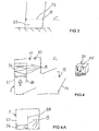
- Fig 3 Illustrated in Fig 3 is a room 1 inside which there is arranged a number of movement detectors 8 so arranged as to sweep above the area 22 in which the persons 2 are required to pass in a labyrinth and, in the event of breaking a beam 23, to indicate transgression, i.e. that the task has not been successfully completed.
- the challenge in this case is to crawl inside a labyrinth that is built with a low height and with movement detectors 8 which sweep above the structure.
- the contestant encounters letters (or similar) inside the maze, which must be remembered on arriving at the end of the task. On arriving at the end of the task, it is necessary to enter the characters that have been noticed on a board with a series of buttons in order for a green light to be displayed.
- Movement detectors have not previously been used in this way, as a means of checking that the rules of a "game” are being followed.
- Figure 4 illustrates the arrangement in a box 24 of an inductive sensor 25 which, when actuated by a metallic object, is so arranged as to indicate that the task has been solved.
- the challenge in this case is to walk over metal tubes 26 without touching metal plates on the wall 27.
- the contestant must then move up to the box 24 with the inductive sensor 25 and place a metal object in the middle in order for a green light to be displayed.
- the movement detector 8 on the return path is intended to prevent the contestant from entering the inductive box by that route, i.e. the wrong way.
- a partition wall 28 is constructed inside the room.
- a metal structure made of tubes and angle-iron is welded together and then suspended with the help of a steel cable.
- Metal plates are attached to the sides. Their function is to sense whether the metal structure comes into contact with them. If this is the case, a red light is displayed. This is an example of the application of an inductive sensor in a new area.
- a movement detector is provided inside a room and is so arranged, in the absence of actuation by movement in the room, as to indicate failure to solve the task.
- the challenge in this case is to move without interruption, for example for one minute. Failure to do so will cause a red light to be displayed.
- a movement sensor is used here in the opposite application. It is necessary for the contestant to move in the sensing direction; otherwise, the contestant has failed to meet the challenge and must leave.
- Illustrated in Fig. 5 is the arrangement of an inductive sensor 4 in a ceiling 29 with a rope 30 extending from the aforementioned sensor 4 with a number of movable blocks 31 threaded onto the rope 30, and with a metal ring 32 at the top.
- the blocks 31 are so arranged as to be caused to be packed together to form a rigid rod, so that the metal ring 32 reaches the sensor 4, which is thereby so arranged as to indicate that the task has been solved correctly.
- the challenge in this case is to stretch the slack rope 30 with the help of the blocks 31 so that it becomes taut. This causes the piece of metal 32 at the top to move up towards a target plate 33 where the inductive sensor 4 is located.
- Clues may be required for this in a previous room.
- a structure in the form of a cage is arranged against a wall 34.
- the front side has a hole 35, into which the hands can be introduced to perform the task.
- a hole is drilled in the sheet of particleboard.
- the inductive sensor is mounted in this. It is attached to the particleboard on its upper side.
- Inside this structure is a nylon rope with wooden blocks on the rope, and at the far end is a small piece of metal.
- the rope is attached to the ceiling with an extra piece of rope, and the other end is secured to the inside of the hole on its lower edge.
- Fig. 6 illustrates how a number of photocell beams 9A from photocells 9 are so arranged as to criss-cross the room and how these are so arranged, in the event of any beam 9A being broken, or in the event of all the beams being broken, as to indicate simultaneously that the task has been solved.
- the challenge in this case is to crawl and climb through the photocell beams 9A without breaking them, or this task can be varied by requiring the contestant to break one or all of the photocell beams simultaneously in order to cause a green light to be displayed.
- This function can be used if it is wished to have the task in a physically undemanding circuit.
- Meshes are used to protect the photocells 9, so that the guests are unable to gain access to them, and reflectors 36 are built into a frame 37 so that they cannot be removed.
- Fig. 7 illustrates how a light relay 38 is located directly opposite a hole 39 in a box 40, which is covered by a Plexiglass sheet 41 or similar, and which, if completely covered by an object or by parts of the body, is so arranged as to indicate that the task has been correctly solved.
- the challenge in this case is to cover the hole completely, in which the light relay 38 is located.
- the aforementioned box is attached to a wall and must be very stable, since it can be exposed to rough treatment.
- Plexiglass sheet 41 must be as clear as glass, but with a structure such that it is not possible to see in through it.
- An incandescent lamp fitting 42 is present above the hole 39. Additional holes 43 without any function may be present to mislead contestants.
- Fig. 8 illustrates the presence of a number of movement detectors 8 in the ceiling in a room, which are so arranged that they sense only a restricted linear area on the floor 44, which is marked out to indicate different areas I, II, III with a number of different colours and/or patterns on them.
- the areas III which the movement detectors 8 are so arranged as to sense are uniformly coloured, etc.
- the challenge in this case is to pass through a labyrinth of invisible, but sensitive walls.
- the floor is painted in three different colours, on two of which it is permissible to move.
- the third, light grey area is dangerous and shows where the movement detectors in the ceiling have their sensing areas.
- the contestant moves through the labyrinth as far as a hand in order to cause a green light to be displayed and then continues to the end of the labyrinth and opens the door to the next room. Even when a green light is displayed, it is still necessary to keep off grey areas until the door has been opened.
- a box 40 for example with a hand on it, is mounted on the wall. Behind the hand is a capacitive sensor which causes a green light to be displayed.
- a suspended, tipping and movably mounted wheel 46 and a number of photocells 9 and movement detectors 8 are arranged in the room illustrated in Fig. 9 to monitor the tipping movements of the wheel and a landing platform 47 and to indicate that the task has not been completed successfully if certain tipping values for the wheel 46 and the bench 47, for example, are exceeded.
- a movement detector 8 on the wheel 46 is directed downwards and causes a red light to be displayed, while the photocell 9 on the wheel 46 is directed downwards to cause a red light to be displayed in the event of excessive movements of the wheel.
- 49 is a weight to keep the box from tipping backwards.
- 50 is a hinge attached to the box and to the floor.
- 51 is a photocell which causes a red light to be displayed when the box tips backwards.
- 8 is a movement detector on the box 47 and is screened and covers the surrounding floor.
- 9 is a photocell which causes a red light to be displayed if the wheel 46 is rotated.
- 52 is a link bearing which permits the wheel 46 to rotate and allows the wheel to tip.
- 53 are rubber bands, which are tensioned to give the wheel 46 a degree of stability.
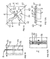
- Fig. 10 illustrates how an actuating rod 55 extends across a box 54 and is so arranged, under the effect of a force actuation device 56, as to be capable of movement horizontally or at an angle downwards along a slotted groove 57.
- a photocell 9 is so arranged as to be capable of sensing the angle of the rod 55 and, in the event of a certain predetermined angle being exceeded, of indicating that the task has not been solved successfully.
- the room contains a wooden box 54 with a rod 55 passing through it.
- the challenge in this case is to move this down at a uniform speed on both sides.
- An excessively large angle causes a red light to be displayed.
- a pull switch 58 causes a green light to be displayed.
- a shock-absorber 56 provides the appropriate resistance.
- FIG. 11 Illustrated in Fig. 11 is a number of magnetic contacts 6 arranged along an irregular track 59 on a board 60, and a moving body 65 capable of being actuated by means of a number of ropes 61-64, which body exhibits a magnet 66, is so arranged as to be caused to move along the track 59 by a number of persons controlling movement of the body by pulling on the ropes 61-64 and, once all the magnetic contacts 6 have been passed, as to indicate that the track has been completed.
- Fig. 12 shows two arms 68, 69 pivotally mounted inside a box 67, the respective outer ends of which extend out from the box via openings.
- One arm 68 exhibits a positive pole 70
- a negative pole contact 71 is arranged inside the box 67.
- the second arm 69 is mounted at right angles to the aforementioned first arm 68 and exhibits a vertical disc 72 at its inner end.
- a reflector 73 is arranged inside the box, and a photocell 9 is present on the first arm 68. Contact between the poles 70,71 indicates that the task has been completed successfully, but a reflection of the photocell 9 indicates that the task has not been completed successfully.
- Two levers extend from the box.
- the levers are mounted on hinges.
- a photocell is mounted on one of the levers, and a wooden plate on the other. If the levers are moved upwards to their full extent at the same time, this will cause a green light to be displayed; otherwise, the photocells will encounter one of the reflectors on the wall behind, and a red light will be displayed.
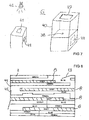
- Fig. 2 shows cubes which are "made” for the display of advertisements.
- the cubes must be placed in the right order with letters facing in the right direction in order to cause a green light to be displayed.
- magnetic contacts are built in on the rear side of the hole that is built in at an angle. It is important to be able to open the structure easily at that point, so that access to the contacts is provided in the event of a fault developing in them.
- the cubes 77 that are constructed must contain magnets 78. These are positioned so that one side of each cube will fit the correct magnetic contact 6 that is located in various positions on the rear of the hole 75 that is built in at an angle. This ensures that only one cube fits in "its" place.
- a net 76 collects the cubes in front of this building.
Landscapes
- Lock And Its Accessories (AREA)
- Geophysics And Detection Of Objects (AREA)
- Vehicle Body Suspensions (AREA)
- Regulating Braking Force (AREA)
- Control By Computers (AREA)
- Conveying And Assembling Of Building Elements In Situ (AREA)
- Exchange Systems With Centralized Control (AREA)
- Debugging And Monitoring (AREA)
- Time Recorders, Dirve Recorders, Access Control (AREA)
- Control Of Non-Electrical Variables (AREA)
- Electrical Discharge Machining, Electrochemical Machining, And Combined Machining (AREA)
Claims (13)
- Spielanordnung für ein Gebäude, in dem eine Anzahl von separaten Räumen (1) vorhanden sind, die Notausgänge und Türen aufweisen, die mit Schlössern versehen sein können, wodurch die Räume als Problemlösebereiche angeordnet sein können, wobei die Spielanordnung Mittel umfasst, die für Personen vorgesehen sind, um durch Geschicklichkeit und Können zu versuchen, verschiedene Aufgaben zu lösen, die dem Kandidaten auf dem Parcours unbekannt sind, ferner umfassend Türschlösser (12) und automatische Mittel, die derart angeordnet sind, dass sie angeben, ob die Aufgabe in dem betreffenden Raum (1) erfolgreich oder nicht erfolgreich gelöst wurde, wobei die automatischen Mittel mit dem betreffenden Türschloss (12) verbunden sind und derart angeordnet sind, dass sie bei der Verwendung bewirken, dass die Tür, die zu dem nächsten Raum in dem Parcours führt, aufgeschlossen wird, oder aufgeschlossen werden wird, wenn der nächste Raum frei wird, nachdem die Aufgabe gelöst wurde, wobei die automatischen Mittel in Verbindung hiermit mindestens eine der folgenden automatisch funktionierenden Steuereinrichtungen umfassen:einen induktiven Sensor (4),einen kapazitiven Sensor (5),einen magnetischen Kontakt (6),ein Lichtrelais (7),einen Bewegungsdetektor (8) undeine Fotozelle (9), wodurch die zuvor genannte Steuereinrichtung (3) mit einer Anzeigeleuchte (10, 11) und mit dem Türschloss (12) für die Tür (13) verbunden ist, die zu dem zuvor genannten Raum (1) führt, wodurch ermöglicht wird, dass automatisch ein Richtig oder Falsch angezeigt wird und das Türschloss (12) aufgeschlossen wird, sobald die richtige Lösung erreicht wurde, und wenn das Problem/die Aufgabe in dem Raum (1) nicht abgeschlossen wurde, dem Kandidaten nicht erlaubt wird, fortzufahren, und er stattdessen durch den Notausgang hinausgehen muss und wieder von vorne beginnen muss.
- Anordnung nach Anspruch 1, dadurch gekennzeichnet, dass sich eine Anzahl von kapazitiven Sensoren (5) hinter einer Platte (14, 15) befinden, in der sich die betreffenden Personen (2) aufhalten müssen und die Platte (14, 15) direkt in Verbindung mit einem Sensor (5) berühren müssen.
- Anordnung nach Anspruch 1, dadurch gekennzeichnet, dass eine Anzahl von Bewegungsdetektoren (8) in einem Labyrinth vorhanden sind und derart angeordnet sind, dass sie über den Bereich streifen, durch den die Personen (2) in einem Labyrinth gehen müssen, und in dem Fall eines Durchbrechens eines Strahls ein Überschreiten angeben.
- Anordnung nach Anspruch 1, dadurch gekennzeichnet, dass in einem Kasten (24) ein induktiver Sensor (25) angeordnet ist, der bei einer Betätigung durch ein metallisches Objekt derart angeordnet ist, dass er angibt, dass die Aufgabe gelöst wurde.
- Anordnung nach Anspruch 1, dadurch gekennzeichnet, dass ein Bewegungsdetektor in einem Raum vorgesehen ist und derart angeordnet ist, dass er bei Nichtvorhandensein einer Betätigung durch eine Bewegung ein Fehlschlagen des Lösens der Aufgabe angibt.
- Anordnung nach Anspruch 1, dadurch gekennzeichnet, dass ein induktiver Sensor (4) in einer Decke (29) angeordnet ist und dass sich ein Seil (30) von dem zuvor genannten Sensor (4) erstreckt, wobei eine Anzahl von bewegbaren Blöcken (31) auf das Seil gefädelt sind und wobei sich ein Metallring (32) an der Oberseite befindet, wobei die Blöcke derart angeordnet sind, dass bewirkt wird, dass sie zusammengeschoben werden, so dass der Metallring (32) den Sensor (4) erreicht, der hierbei derart angeordnet ist, dass er angibt, dass die Aufgabe korrekt gelöst wurde.
- Anordnung nach Anspruch 1, dadurch gekennzeichnet, dass eine Anzahl von Fotozellenstrahlen (9A) derart angeordnet sind, dass sie kreuz und quer durch den Raum verlaufen und dass diese derart angeordnet sind, dass sie in dem Fall, dass irgendein Strahl (9A) durchbrochen wird, oder in dem Fall, dass mehrere Strahlen (9A) durchbrochen werden, gleichzeitig angeben, dass die Aufgabe gelöst wurde.
- Anordnung nach Anspruch 1, dadurch gekennzeichnet, dass ein Lichtrelais (38) direkt gegenüber einem durch eine Plexiglasplatte (41) oder ähnliches abgedeckten Loch (39) angeordnet ist, das derart angeordnet ist, dass es, wenn es vollständig abgedeckt ist, angibt, dass die Aufgabe korrekt gelöst wurde.
- Anordnung nach Anspruch 1, dadurch gekennzeichnet, dass in der Decke in einem Raum eine Anzahl von Bewegungsdetektoren (8) vorhanden sind, die derart angeordnet sind, dass sie nur einen begrenzten linearen Bereich auf dem Boden erfassen, dass der Boden markiert ist, um verschiedene Bereiche (I-III) mit einer Anzahl von verschiedenen Farben und/oder Mustern zu bezeichnen, und dass die Bereiche (III), für die die Bewegungsdetektoren (8) angeordnet sind, um sie zu erfassen, eine einheitliche Farbe etc. aufweisen.
- Anordnung nach Anspruch 1, dadurch gekennzeichnet, dass eine Anzahl von Fotozellen (9) und Bewegungsdetektoren (8) derart an einem gefederten, kippenden und bewegbar angebrachten Rad (46) angeordnet sind, dass sie die Kippbewegungen des Rads und eines Podests (47) überwachen und angeben, dass die Aufgabe nicht erfolgreich abgeschlossen wurde, wenn bestimmte Kippwerte überstiegen sind.
- Anordnung nach Anspruch 1, dadurch gekennzeichnet, dass sich ein Betätigungsstab (55) durch einen Kasten (54) erstreckt und derart angeordnet ist, dass er unter dem Einfluss einer Kraftbetätigungseinrichtung (56) zu einer Bewegung entlang einer nutförmigen Rille (57) fähig ist, und dass eine Fotozelle (9) derart angeordnet ist, dass sie den Winkel des Stabs (55) erfassen kann, und in dem Fall, dass ein bestimmter vorbestimmter Winkel überstiegen wird, angeben kann, dass die Aufgabe nicht erfolgreich gelöst wurde.
- Anordnung nach Anspruch 1, dadurch gekennzeichnet, dass eine Anzahl von magnetischen Kontakten (6) entlang einer unregelmäßigen Bahn (59) auf einem Brett (60) angeordnet ist, und dass ein sich bewegender Körper (65), der durch eine Anzahl von Seilen (61-64) betätigt werden kann, wobei der Körper einen Magnet (66) aufweist, derart angeordnet ist, dass bewirkt wird, dass er sich entlang der Bahn (59) bewegt, und dass, sobald alle magnetischen Kontakte (6) passiert wurden, angegeben wird, dass die Bahn (59) abgeschlossen wurde.
- Anordnung nach Anspruch 1, dadurch gekennzeichnet, dass zwei Arme (68, 69) verschwenkbar in einem Kasten (67) angeordnet sind und sich an ihren jeweiligen äußeren Enden aus dem Kasten erstrecken, dass ein Arm einen positiven Pol (70) und eine Fotozelle (9) in dem Kasten aufweist, dass der zweite Arm (69) unter rechten Winkeln zu dem zuvor genannten ersten Arm (68) angebracht ist und eine vertikale Scheibe (72) an seinem inneren Ende aufweist, dass ein Kontakt (71) eines negativen Pols in dem Kasten (67) angeordnet ist, und dass ein Reflektor (73) in dem Kasten (67) angeordnet ist, wobei ein Kontakt zwischen den Polen (70, 71) angibt, dass die Aufgabe erfolgreich abgeschlossen wurde, jedoch eine Reflexion der Fotozelle (9) angibt, dass die Aufgabe nicht erfolgreich abgeschlossen wurde.
Applications Claiming Priority (2)
| Application Number | Priority Date | Filing Date | Title |
|---|---|---|---|
| SE9802758 | 1998-08-18 | ||
| SE9802758A SE514622C2 (sv) | 1998-08-18 | 1998-08-18 | Anordning för kontroll av uppgiftslösning |
Publications (3)
| Publication Number | Publication Date |
|---|---|
| EP0980698A2 EP0980698A2 (de) | 2000-02-23 |
| EP0980698A3 EP0980698A3 (de) | 2000-11-15 |
| EP0980698B1 true EP0980698B1 (de) | 2007-10-10 |
Family
ID=20412274
Family Applications (1)
| Application Number | Title | Priority Date | Filing Date |
|---|---|---|---|
| EP99115726A Expired - Lifetime EP0980698B1 (de) | 1998-08-18 | 1999-08-10 | Kontrolleinrichtung für Lösung von Problemen |
Country Status (7)
| Country | Link |
|---|---|
| EP (1) | EP0980698B1 (de) |
| AT (1) | ATE375188T1 (de) |
| DE (1) | DE69937273T2 (de) |
| DK (1) | DK0980698T3 (de) |
| ES (1) | ES2296362T3 (de) |
| NO (1) | NO326467B1 (de) |
| SE (1) | SE514622C2 (de) |
Cited By (1)
| Publication number | Priority date | Publication date | Assignee | Title |
|---|---|---|---|---|
| US10507378B2 (en) | 2007-09-21 | 2019-12-17 | Boda Borg Corp. | Live action multi-track skills game |
Family Cites Families (2)
| Publication number | Priority date | Publication date | Assignee | Title |
|---|---|---|---|---|
| US4695058A (en) * | 1984-01-31 | 1987-09-22 | Photon Marketing Limited | Simulated shooting game with continuous transmission of target identification signals |
| US5393074A (en) * | 1993-09-07 | 1995-02-28 | Bear; Thomas | Modular electronic gaming system |
-
1998
- 1998-08-18 SE SE9802758A patent/SE514622C2/sv not_active IP Right Cessation
-
1999
- 1999-07-12 NO NO19993420A patent/NO326467B1/no not_active IP Right Cessation
- 1999-08-10 AT AT99115726T patent/ATE375188T1/de not_active IP Right Cessation
- 1999-08-10 DE DE69937273T patent/DE69937273T2/de not_active Expired - Lifetime
- 1999-08-10 ES ES99115726T patent/ES2296362T3/es not_active Expired - Lifetime
- 1999-08-10 DK DK99115726T patent/DK0980698T3/da active
- 1999-08-10 EP EP99115726A patent/EP0980698B1/de not_active Expired - Lifetime
Cited By (1)
| Publication number | Priority date | Publication date | Assignee | Title |
|---|---|---|---|---|
| US10507378B2 (en) | 2007-09-21 | 2019-12-17 | Boda Borg Corp. | Live action multi-track skills game |
Also Published As
| Publication number | Publication date |
|---|---|
| SE9802758L (sv) | 2000-02-19 |
| DK0980698T3 (da) | 2008-02-11 |
| ATE375188T1 (de) | 2007-10-15 |
| SE514622C2 (sv) | 2001-03-26 |
| EP0980698A2 (de) | 2000-02-23 |
| SE9802758D0 (sv) | 1998-08-18 |
| ES2296362T3 (es) | 2008-04-16 |
| NO326467B1 (no) | 2008-12-08 |
| NO993420L (no) | 2000-02-21 |
| DE69937273D1 (de) | 2007-11-22 |
| NO993420D0 (no) | 1999-07-12 |
| DE69937273T2 (de) | 2008-07-10 |
| EP0980698A3 (de) | 2000-11-15 |
Similar Documents
| Publication | Publication Date | Title |
|---|---|---|
| EP2397202B1 (de) | Spielplatzausrüstung | |
| US4037685A (en) | Building evacuation system | |
| JP2009082355A (ja) | 弾球遊技機 | |
| EP0980698B1 (de) | Kontrolleinrichtung für Lösung von Problemen | |
| US5709604A (en) | Ring-swing skill game | |
| US2776835A (en) | Racing game apparatus | |
| US3817519A (en) | Play control device for amusement game | |
| US3785650A (en) | Manually controlled electric pinball game | |
| JP6572173B2 (ja) | 遊技機 | |
| TW583010B (en) | Game device and method for controlling game device | |
| JP2958953B2 (ja) | 弾球遊技機 | |
| WO1984002281A1 (en) | Racing betting game | |
| JPH01170484A (ja) | 弾球遊技機 | |
| JP2018068520A (ja) | ぱちんこ遊技機 | |
| CN216061980U (zh) | 一种模拟金库游戏设备 | |
| US5344154A (en) | Board game with trap doors | |
| JPH03297486A (ja) | 遊戯施設 | |
| US4384720A (en) | Changeable circuit controlling switch assembly | |
| JPH072191B2 (ja) | パチンコ遊技機 | |
| JP2014150902A (ja) | 遊技機 | |
| CN210786198U (zh) | 一种应用于积木机器人的比赛场地 | |
| JPH0221113Y2 (de) | ||
| JP3008131U (ja) | クレーンゲーム装置 | |
| JP2560973Y2 (ja) | クレーンゲーム装置 | |
| KR102176083B1 (ko) | 원반투척게임기 |
Legal Events
| Date | Code | Title | Description |
|---|---|---|---|
| PUAI | Public reference made under article 153(3) epc to a published international application that has entered the european phase |
Free format text: ORIGINAL CODE: 0009012 |
|
| AK | Designated contracting states |
Kind code of ref document: A2 Designated state(s): AT BE CH CY DE DK ES FI FR GB GR IE IT LI LU MC NL PT SE |
|
| AX | Request for extension of the european patent |
Free format text: AL;LT;LV;MK;RO;SI |
|
| PUAL | Search report despatched |
Free format text: ORIGINAL CODE: 0009013 |
|
| AK | Designated contracting states |
Kind code of ref document: A3 Designated state(s): AT BE CH CY DE DK ES FI FR GB GR IE IT LI LU MC NL PT SE |
|
| AX | Request for extension of the european patent |
Free format text: AL;LT;LV;MK;RO;SI |
|
| 17P | Request for examination filed |
Effective date: 20010504 |
|
| AKX | Designation fees paid |
Free format text: AT BE CH CY DE DK ES FI FR GB GR IE IT LI LU MC NL PT SE |
|
| RIN1 | Information on inventor provided before grant (corrected) |
Inventor name: SAELL JANNE Inventor name: WALTHER OVE Inventor name: ANDERSSON BOERJE Inventor name: OEDMARK KATARINA |
|
| 17Q | First examination report despatched |
Effective date: 20040325 |
|
| RAP1 | Party data changed (applicant data changed or rights of an application transferred) |
Owner name: BODA BORG INTERNATIONAL AB |
|
| GRAP | Despatch of communication of intention to grant a patent |
Free format text: ORIGINAL CODE: EPIDOSNIGR1 |
|
| 17Q | First examination report despatched |
Effective date: 20040325 |
|
| GRAS | Grant fee paid |
Free format text: ORIGINAL CODE: EPIDOSNIGR3 |
|
| GRAA | (expected) grant |
Free format text: ORIGINAL CODE: 0009210 |
|
| AK | Designated contracting states |
Kind code of ref document: B1 Designated state(s): AT BE CH CY DE DK ES FI FR GB GR IE IT LI LU MC NL PT SE |
|
| REG | Reference to a national code |
Ref country code: GB Ref legal event code: FG4D |
|
| REG | Reference to a national code |
Ref country code: CH Ref legal event code: EP |
|
| REG | Reference to a national code |
Ref country code: IE Ref legal event code: FG4D |
|
| REF | Corresponds to: |
Ref document number: 69937273 Country of ref document: DE Date of ref document: 20071122 Kind code of ref document: P |
|
| REG | Reference to a national code |
Ref country code: SE Ref legal event code: TRGR |
|
| REG | Reference to a national code |
Ref country code: DK Ref legal event code: T3 |
|
| REG | Reference to a national code |
Ref country code: ES Ref legal event code: FG2A Ref document number: 2296362 Country of ref document: ES Kind code of ref document: T3 |
|
| PG25 | Lapsed in a contracting state [announced via postgrant information from national office to epo] |
Ref country code: LI Free format text: LAPSE BECAUSE OF FAILURE TO SUBMIT A TRANSLATION OF THE DESCRIPTION OR TO PAY THE FEE WITHIN THE PRESCRIBED TIME-LIMIT Effective date: 20071010 Ref country code: CH Free format text: LAPSE BECAUSE OF FAILURE TO SUBMIT A TRANSLATION OF THE DESCRIPTION OR TO PAY THE FEE WITHIN THE PRESCRIBED TIME-LIMIT Effective date: 20071010 |
|
| REG | Reference to a national code |
Ref country code: CH Ref legal event code: PL |
|
| PG25 | Lapsed in a contracting state [announced via postgrant information from national office to epo] |
Ref country code: PT Free format text: LAPSE BECAUSE OF FAILURE TO SUBMIT A TRANSLATION OF THE DESCRIPTION OR TO PAY THE FEE WITHIN THE PRESCRIBED TIME-LIMIT Effective date: 20080310 |
|
| ET | Fr: translation filed | ||
| PG25 | Lapsed in a contracting state [announced via postgrant information from national office to epo] |
Ref country code: AT Free format text: LAPSE BECAUSE OF FAILURE TO SUBMIT A TRANSLATION OF THE DESCRIPTION OR TO PAY THE FEE WITHIN THE PRESCRIBED TIME-LIMIT Effective date: 20071010 |
|
| PLBE | No opposition filed within time limit |
Free format text: ORIGINAL CODE: 0009261 |
|
| STAA | Information on the status of an ep patent application or granted ep patent |
Free format text: STATUS: NO OPPOSITION FILED WITHIN TIME LIMIT |
|
| PG25 | Lapsed in a contracting state [announced via postgrant information from national office to epo] |
Ref country code: BE Free format text: LAPSE BECAUSE OF FAILURE TO SUBMIT A TRANSLATION OF THE DESCRIPTION OR TO PAY THE FEE WITHIN THE PRESCRIBED TIME-LIMIT Effective date: 20071010 |
|
| 26N | No opposition filed |
Effective date: 20080711 |
|
| PG25 | Lapsed in a contracting state [announced via postgrant information from national office to epo] |
Ref country code: GR Free format text: LAPSE BECAUSE OF FAILURE TO SUBMIT A TRANSLATION OF THE DESCRIPTION OR TO PAY THE FEE WITHIN THE PRESCRIBED TIME-LIMIT Effective date: 20080111 |
|
| PG25 | Lapsed in a contracting state [announced via postgrant information from national office to epo] |
Ref country code: MC Free format text: LAPSE BECAUSE OF NON-PAYMENT OF DUE FEES Effective date: 20080831 |
|
| PG25 | Lapsed in a contracting state [announced via postgrant information from national office to epo] |
Ref country code: CY Free format text: LAPSE BECAUSE OF FAILURE TO SUBMIT A TRANSLATION OF THE DESCRIPTION OR TO PAY THE FEE WITHIN THE PRESCRIBED TIME-LIMIT Effective date: 20071010 |
|
| PGFP | Annual fee paid to national office [announced via postgrant information from national office to epo] |
Ref country code: ES Payment date: 20090722 Year of fee payment: 11 |
|
| PG25 | Lapsed in a contracting state [announced via postgrant information from national office to epo] |
Ref country code: LU Free format text: LAPSE BECAUSE OF NON-PAYMENT OF DUE FEES Effective date: 20080810 |
|
| PG25 | Lapsed in a contracting state [announced via postgrant information from national office to epo] |
Ref country code: FI Free format text: LAPSE BECAUSE OF NON-PAYMENT OF DUE FEES Effective date: 20100810 |
|
| REG | Reference to a national code |
Ref country code: ES Ref legal event code: FD2A Effective date: 20111019 |
|
| PG25 | Lapsed in a contracting state [announced via postgrant information from national office to epo] |
Ref country code: ES Free format text: LAPSE BECAUSE OF NON-PAYMENT OF DUE FEES Effective date: 20100811 |
|
| PGRI | Patent reinstated in contracting state [announced from national office to epo] |
Ref country code: FI Effective date: 20110830 |
|
| REG | Reference to a national code |
Ref country code: FR Ref legal event code: PLFP Year of fee payment: 18 |
|
| REG | Reference to a national code |
Ref country code: FR Ref legal event code: PLFP Year of fee payment: 19 |
|
| REG | Reference to a national code |
Ref country code: FR Ref legal event code: PLFP Year of fee payment: 20 |
|
| PGFP | Annual fee paid to national office [announced via postgrant information from national office to epo] |
Ref country code: FR Payment date: 20180828 Year of fee payment: 20 Ref country code: IE Payment date: 20180820 Year of fee payment: 20 Ref country code: IT Payment date: 20180808 Year of fee payment: 20 Ref country code: NL Payment date: 20180821 Year of fee payment: 20 |
|
| PGFP | Annual fee paid to national office [announced via postgrant information from national office to epo] |
Ref country code: DK Payment date: 20180726 Year of fee payment: 20 Ref country code: FI Payment date: 20180807 Year of fee payment: 20 Ref country code: SE Payment date: 20180716 Year of fee payment: 20 Ref country code: GB Payment date: 20180802 Year of fee payment: 20 |
|
| PGFP | Annual fee paid to national office [announced via postgrant information from national office to epo] |
Ref country code: DE Payment date: 20181030 Year of fee payment: 20 |
|
| REG | Reference to a national code |
Ref country code: DE Ref legal event code: R071 Ref document number: 69937273 Country of ref document: DE |
|
| REG | Reference to a national code |
Ref country code: DK Ref legal event code: EUP Effective date: 20190810 |
|
| REG | Reference to a national code |
Ref country code: NL Ref legal event code: MK Effective date: 20190809 |
|
| REG | Reference to a national code |
Ref country code: GB Ref legal event code: PE20 Expiry date: 20190809 |
|
| REG | Reference to a national code |
Ref country code: SE Ref legal event code: EUG |
|
| REG | Reference to a national code |
Ref country code: IE Ref legal event code: MK9A |
|
| PG25 | Lapsed in a contracting state [announced via postgrant information from national office to epo] |
Ref country code: IE Free format text: LAPSE BECAUSE OF EXPIRATION OF PROTECTION Effective date: 20190810 |
|
| PG25 | Lapsed in a contracting state [announced via postgrant information from national office to epo] |
Ref country code: GB Free format text: LAPSE BECAUSE OF EXPIRATION OF PROTECTION Effective date: 20190809 |