EP0980035B1 - Einphasiger Transformator mit Mittelabgriff - Google Patents
Einphasiger Transformator mit Mittelabgriff Download PDFInfo
- Publication number
- EP0980035B1 EP0980035B1 EP99106958A EP99106958A EP0980035B1 EP 0980035 B1 EP0980035 B1 EP 0980035B1 EP 99106958 A EP99106958 A EP 99106958A EP 99106958 A EP99106958 A EP 99106958A EP 0980035 B1 EP0980035 B1 EP 0980035B1
- Authority
- EP
- European Patent Office
- Prior art keywords
- coil
- coils
- layers
- phase
- wire type
- Prior art date
- Legal status (The legal status is an assumption and is not a legal conclusion. Google has not performed a legal analysis and makes no representation as to the accuracy of the status listed.)
- Expired - Lifetime
Links
Images


Classifications
-
- G—PHYSICS
- G05—CONTROLLING; REGULATING
- G05F—SYSTEMS FOR REGULATING ELECTRIC OR MAGNETIC VARIABLES
- G05F1/00—Automatic systems in which deviations of an electric quantity from one or more predetermined values are detected at the output of the system and fed back to a device within the system to restore the detected quantity to its predetermined value or values, i.e. retroactive systems
- G05F1/10—Regulating voltage or current
- G05F1/12—Regulating voltage or current wherein the variable actually regulated by the final control device is AC
- G05F1/24—Regulating voltage or current wherein the variable actually regulated by the final control device is AC using bucking or boosting transformers as final control devices
-
- H—ELECTRICITY
- H01—ELECTRIC ELEMENTS
- H01F—MAGNETS; INDUCTANCES; TRANSFORMERS; SELECTION OF MATERIALS FOR THEIR MAGNETIC PROPERTIES
- H01F27/00—Details of transformers or inductances, in general
- H01F27/28—Coils; Windings; Conductive connections
- H01F27/2823—Wires
-
- H—ELECTRICITY
- H01—ELECTRIC ELEMENTS
- H01F—MAGNETS; INDUCTANCES; TRANSFORMERS; SELECTION OF MATERIALS FOR THEIR MAGNETIC PROPERTIES
- H01F27/00—Details of transformers or inductances, in general
- H01F27/34—Special means for preventing or reducing unwanted electric or magnetic effects, e.g. no-load losses, reactive currents, harmonics, oscillations, leakage fields
Definitions
- the present invention relates generally to a single-phase three-wire type transformer and, more particularly, to a single-phase three-wire type transformer in which a secondary coil is divided into a plurality of coils to be arranged in a core so that these coils are connected in an intersected condition in order to avoid an imbalance in the secondary voltage.
- Some single-phase three-wire type transformers have a structure so that a secondary coil is divided into a plurality of coils to avoid an imbalance in secondary voltages (due to a connection state of loads) to be arranged in a core so that these coils are connected in an intersected condition.
- Such single-phase three-wire type transformers are referred to as division intersection connections and generally have been widely used.
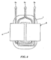
- a single-phase three-wire type transformer adopting the division intersection connection includes a core 1 of an iron frame of an approximately square configuration, and conductors are wound opposite on two locations on the core 1, respectively, to form a coil A and coil B.
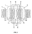
- these coils A and B are not merely an independent primary or secondary coil, respectively, but make up three-layer structures with three overlapped and wound coils, respectively, as shown in Figure 5.
- the coil A is constituted so that secondary coils 21a and 22a and a primary coil 11a are overlapped and wound in sequence from the inside of the core 1.
- the coil B is similarly constituted so that secondary coils 21b and 22b and a primary coil 11b are overlapped and wound in sequence from the inside of the core 1.
- connections are made so that the primary coils 11a and 11b are combined in series with the respective other ends of the coils to be set as primary terminals 1a and 1b in the primary coils.
- the secondary coils 21a and 22b are combined at a connection point 2x and the secondary coils 22a and 21b are connected at a connection point 2y to cause the connections to be intersected.
- the other ends of the secondary coils 22a and 22b are combined to make this connection point a secondary terminal 2n, and the other end of the secondary coil 21a is made a secondary terminal 2u and also the other end of the secondary coil 21b is made a secondary terminal 2v.
- each secondary coil is made double by winding two parallel winding conductors of small diameter on the core 1, and secondary coils are constituted by connecting each doubled secondary coil in an intersecting condition.
- the secondary coil 21a has a duplex structure of coils 211a and 212a made by winding two parallel winding conductors of small diameter.
- the secondary coils 22a, 21b, and 22b have a duplex structure of coils 221a and 222a, coils 211b and 212b, and coils 221b and 222b, respectively.
- these duplex coils are connected in parallel by combining the respective lead portions extending from the ends of the duplex coils.
- the combinations between the coils as discussed hereinbefore, the secondary coils 21a and 22b are combined at the connection point 2x and the secondary coils 22a and 21b are connected at the connection point 2y causing the connections to be intersected.
- each secondary coil has a duplex structure, so that the electric current capacity is increased substantially to double that of a conductor with a small diameter, and because the diameter of the winding conductor is small, the eddy current loss can be suppressed to a low level.
- a single-phase three-wire type transformer of the prior art described above has a disadvantage inasmuch as when each secondary coil is configured with a duplex structure, four closed circuits are formed among the secondary terminals 2n, 2u, and 2v and connection points 2x and 2y of the intersection connections so that circulating currents according to electromotive forces originating from the distribution of magnetic flux density may flow through these closed circuits, resulting in a loss W.
- a closed circuit C1 with a current circulating through the secondary terminal 2u, coil 211a, connection point 2x, coil 212a, and the secondary terminal 2u
- a closed circuit C2 with a current circulating through the secondary terminal 2n, coil 222b, connection point 2v, coil 212b, and the secondary terminal 2n
- a closed circuit C3 with a current circulating through the secondary terminal 2v, coil 212b, connection point 2y, coil 211b, and the secondary terminal 2v
- a closed circuit C4 with a current circulating through the secondary terminal 2n, coil 221a, connection point 2y, coil 222a, and the secondary terminal 2n.
- the magnetic flux density reaches a peak value on an interface of the primary and secondary coils, as shown in Figure 2, and the electromotive force (V) is generated in proportion to this magnetic flux density (B), so that the circulating current flows in each closed circuit.
- V the peak value of the electromotive force
- the secondary coils 21a and 22a are composed of four layers, so the respective electromotive forces among each of the layers become (1/4)V between layers 1 and 2, (2/4)V between layers 2 and 3, and (3/4)V between layers 3 and 4.
- the secondary coils 21b and 22b are composed of four layers, so the respective electromotive forces among each of the layers become (1/4)V between layers 1 and 2, (2/4)V between layers 2 and 3, and (3/4)V between layers 3 and 4.
- circulating currents may flow based on the electromotive forces generated among each of the layers of the secondary coils in each of the closed circuits, and when resistance component of each closed circuit is assumed to be R, the loss in the closed circuit C1 will become
- each closed circuit is equivalent to a resistor value generated when two coils constituting a duplex coil are connected in parallel, and the resistor value of a winding conductor itself of a coil is so small that the variation of resistor values among the coils so completed is very. Consequently, all of the resistor values may be considered to be the same value.
- EP 0 309 837 A1 discloses a transformer whose secondary winding comprises two parallel conductors and is arranged in several winding portion axially spaced along the axis of a longitudinal core. The arrangement of the inner and outer conductors is exchanged between adjacent winding portions such that the voltages induced by the main magnetic flux will be equal in the two conductors.
- the present invention has been made in view of the above-described background, and therefore, has objects to solve the above-described problems, to enable the induced magnetic flux to be balanced on the magnetic path regardless of the connection condition according to the division intersection connection, and also to enable the electric current circulating through the inside of a circuit of a transformer to be reduced even when secondary coils are formed with a duplex coil con Figured by winding two conductors in parallel, thereby providing a single-phase three-wire type transformer which can reduce the loss in the coils.
- a single-phase three-wire type transformer according to the present invention comprises the features of claim 1.
- the secondary coil according to the present invention is formed by duplex coils with two conductors wound in parallel, and the intersecting connection for one duplex coil is connected in series with the other duplex coil, so that the secondary side of the transformer forms an intersecting connection of duplex structure when viewed from the secondary terminals.
- each of the connection points for the intersecting connection is independent electrically without contacting another connection point, so that only two closed circuits are formed. This number is half of that of a conventional transformer described above.
- each of the closed circuits circulating currents based on the electromotive forces originating from the distribution of magnetic flux density will flow through each of the closed circuits.
- the coils of each closed circuit are disposed dispersedly in two locations in the core and the directions of the electromotive forces (the circulating currents) of each closed circuit are made the reverse of the other, the circulating currents are cancel each other so as to be decreased and these currents flow from the high potential side toward the low potential one.
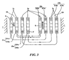
- Figure 1 is a schematic diagram of a single-phase three-wire type transformer of one embodiment according to the present invention.
- the single-phase three-wire type transformer similar in appearance to the conventional example shown in Figure 4, includes a core 1 made of an iron frame of approximately square configuration. Conductors are wound on two opposing locations of the core 1, to form a coil A and coil B, respectively.
- the coils A and B make up three-layer structures with three overlapped and wound coils, respectively.
- the coil A is constituted so that secondary coils 21a and 22a and a primary coil 11a are overlapped and wound in sequence from the inside of the core 1.
- the coil B is similarly constituted so that secondary coils 21b and 22b and a primary coil lib are overlapped and wound in sequence from the inside of the core 1.
- the secondary coils 21a, 22a, 21b, and 22b adopt a duplex coil configuration. That is, two winding conductors of small diameter are wound on the core 1 in parallel, and the secondary coil 21a has a duplex structure of coils 211a and 212a. Similarly, the secondary coils 22a, 21b, and 22b have a duplex structure of coils 221a and 222a, coils 211b and 212b, and coils 221b and 222b, respectively.
- duplex coils are configured so that two parallel winding conductors are connected in series, that is, as for the combinations between duplex coils, each one end of the coils 211a and 222b is combined at the connection point p, each one end of the coils 212a and 221b at the connection point q, each one end of the coils 221a and 212b at the connection point r, and each one end of the coils 222a and 211b at the connection point s to cause the connections to be intersected.
- connection point a secondary terminal 2n all of the other ends of the coils 221a and 222a and coils 221b and 222b in outer layers are combined to make this connection point a secondary terminal 2n, and the other ends of the coils 211a and 212a of one inner layer are connected at the conductor portion of their lead wires to make the connection point a secondary terminal 2u. Similarly, the other ends of the coils 211b and 212b of the other inner layer are connected at the conductor portion of their lead wires to make the connection point a secondary terminal 2v.
- the secondary side of the transformer configures intersecting connections of duplex structure when viewed from the secondary terminals 2n, 2u, and 2v, and each of the connection points p, q, r, and s is independent electrically without contacting any of the other connection points, so that only two closed circuits are formed.
- a closed circuit C5 with a current circulating through the secondary terminal 2u, coil 211a, connection point p, coil 222b, secondary terminal 2n, coil 221b, connection point q, coil 212a, and secondary terminal 2u between the secondary terminals 2u and 2n
- a closed circuit C6 with a current circulating through the secondary terminal 2v, coil 211b, connection point s, coil 222a, secondary terminal 2n, coil 221a, connection point r, coil 212b, and secondary terminal 2v between the secondary terminals 2v and 2n.
- the electromotive force (1/4)V between layers 1 and 2 of the secondary coils 21b and 22b is subtracted from the electromotive force (3/4)V between layers 3 and 4 of the secondary coils 21a and 22a in the closed circuit C6.
- a resistance component of each of the closed circuits C1, C2, C3, and C4 described above is assumed to be R
- the resistance component in these closed circuits C5 and C6 becomes 2R, so that the loss in the closed circuit C5 will become
- a loss in the closed circuit C6 will become
- the single-phase three-wire type transformer according to the present invention is configured so that the intersecting connection for one duplex coil is connected in series with the other duplex coil, so that two closed circuits are formed, corresponding to half of the conventional transformer previously described.
- the directions of the electromotive forces are mutually reversed in coils A and B, so that the electromotive forces will be canceled between the two coils, allowing the circulating currents to be reduced.
- the loss W will become (1/4)x(V 2 /R) as previously described, one fifth of that of the above-described conventional transformer.
- the single-phase three-wire type transformer according to the present invention can be by simply connecting the two lead portions of thin winding conductors at each of the connection points p, q, r, and s of the secondary coils. Because the number of the thin winding conductors connected is half that of the conventional transform, crimp contacts of a small size can be used and a small and light application tool can be utilized, allowing the manufacturing work to be facilitated. Additionally, this pressure work requires only bending the lead portions of a thin winding conductor one by one to form the connection points, so that the connection points can be easily formed using a low power, resulting in excellent workability.
- the single-phase three-wire type transformer according to the present invention can achieve the effect of reducing loss in addition to enabling the induced magnetic flux to be balanced on the magnetic path regardless of the connection condition according to the division intersection connection. That is, the intersecting connection for one duplex coil constituting a secondary coil is connected in series with the other duplex coil, so that the secondary side of the transformer is caused to be the intersecting connection of the duplex configuration when viewed from the secondary terminal. Thus only two closed circuits are formed (this number corresponds to half of that of the conventional transformer described above).
- each closed circuit Although circulating currents based on the electromotive forces originating from the distribution of magnetic flux density will flow through each closed circuit, the coils of each closed circuit are arranged dispersedly in two locations on the core and the directions of the electromotive forces (circulating currents) are reversed, so that the electromotive forces are canceled between the two closed circuits to reduce the circulating currents.
- the circulating currents will flow from the high potential side toward the low potential side. Accordingly, the current circulating through inside of the circuit of the transformer can be reduced, thereby achieving an excellent effect in reducing the loss in the transformer.
Landscapes
- Engineering & Computer Science (AREA)
- Power Engineering (AREA)
- Physics & Mathematics (AREA)
- Electromagnetism (AREA)
- General Physics & Mathematics (AREA)
- Radar, Positioning & Navigation (AREA)
- Automation & Control Theory (AREA)
- Coils Of Transformers For General Uses (AREA)
Claims (1)
- Einphasen-Dreileiter-Transformator, bei dem eine sekundäre Spule in vier (21a, 21b, 22a, 22b) unterteilt ist, von denen zwei (21a, 22a) auf einer ersten Spule (A) und die anderen beiden (21b, 22b) auf einer sekundären Spule (B) in einer Zweischicht-Struktur angeordnet sind, wobei die erste Spule (A) und die zweite Spule (B) in einer ersten und einer zweiten Anordnungsstelle nahe beieinander auf zwei parallelen Seiten eines in etwa quadratischen Kernes (1) angeordnet sind und die beiden Schichten aus einer inneren Schicht und einer äußeren Schicht in einem sich überschneidenden Zustand zwischen beiden Anordnungsstellen verbunden sind, um Verstimmungen in Sekundärspannungen zu vermeiden, wobei jede der sekundären Spulen, die in vier (21a, 21b, 22a, 22b) unterteilt ist, zu einer Duplexspule (211a, 212a; 211b, 212b; 221a, 222a; 221b, 222b) gemacht ist durch Anordnen von zwei Wicklungsleitern parallel und Wickeln derselben auf den Kern (1), und dass beim Verbinden der beiden Schichten in dem sich überschneidenden Zustand die beiden parallelen Wicklungsleiter einer Duplexspule in Reihe mit denen der anderen Duplexspule verbunden sind.
Applications Claiming Priority (2)
| Application Number | Priority Date | Filing Date | Title |
|---|---|---|---|
| JP22678398 | 1998-08-11 | ||
| JP22678398A JP3367427B2 (ja) | 1998-08-11 | 1998-08-11 | 単相三線式変圧器 |
Publications (2)
| Publication Number | Publication Date |
|---|---|
| EP0980035A1 EP0980035A1 (de) | 2000-02-16 |
| EP0980035B1 true EP0980035B1 (de) | 2003-02-05 |
Family
ID=16850553
Family Applications (1)
| Application Number | Title | Priority Date | Filing Date |
|---|---|---|---|
| EP99106958A Expired - Lifetime EP0980035B1 (de) | 1998-08-11 | 1999-04-08 | Einphasiger Transformator mit Mittelabgriff |
Country Status (4)
| Country | Link |
|---|---|
| US (1) | US6049266A (de) |
| EP (1) | EP0980035B1 (de) |
| JP (1) | JP3367427B2 (de) |
| DE (1) | DE69905223T2 (de) |
Families Citing this family (15)
| Publication number | Priority date | Publication date | Assignee | Title |
|---|---|---|---|---|
| US8624696B2 (en) * | 2004-06-17 | 2014-01-07 | Grant A. MacLennan | Inductor apparatus and method of manufacture thereof |
| US8624702B2 (en) | 2004-06-17 | 2014-01-07 | Grant A. MacLennan | Inductor mounting apparatus and method of use thereof |
| US8373530B2 (en) | 2004-06-17 | 2013-02-12 | Grant A. MacLennan | Power converter method and apparatus |
| US9257895B2 (en) | 2004-06-17 | 2016-02-09 | Grant A. MacLennan | Distributed gap inductor filter apparatus and method of use thereof |
| US8902034B2 (en) | 2004-06-17 | 2014-12-02 | Grant A. MacLennan | Phase change inductor cooling apparatus and method of use thereof |
| US8519813B2 (en) * | 2004-06-17 | 2013-08-27 | Grant A. MacLennan | Liquid cooled inductor apparatus and method of use thereof |
| US9300197B2 (en) | 2004-06-17 | 2016-03-29 | Grant A. MacLennan | High frequency inductor filter apparatus and method of use thereof |
| US8902035B2 (en) | 2004-06-17 | 2014-12-02 | Grant A. MacLennan | Medium / high voltage inductor apparatus and method of use thereof |
| US8947187B2 (en) | 2005-06-17 | 2015-02-03 | Grant A. MacLennan | Inductor apparatus and method of manufacture thereof |
| US7528692B2 (en) * | 2006-04-14 | 2009-05-05 | Jonathan Paul Nord | Voltage stress reduction in magnetics using high resistivity materials |
| US8816808B2 (en) | 2007-08-22 | 2014-08-26 | Grant A. MacLennan | Method and apparatus for cooling an annular inductor |
| CN102360845B (zh) * | 2011-06-09 | 2013-06-19 | 常熟市森源电气科技有限公司 | 单相多抽头隔离变压器 |
| KR101201291B1 (ko) | 2012-05-08 | 2012-11-14 | 안희석 | 정전차폐, 서지 및 노이즈 방지를 위한 역방향 2중 권선 결합 변압기 |
| US9640312B2 (en) * | 2014-08-19 | 2017-05-02 | General Electric Company | Multi-phase common mode choke |
| ES2890931T3 (es) * | 2018-10-31 | 2022-01-25 | Hitachi Energy Switzerland Ag | Componente eléctrico, especialmente transformador o inductor |
Family Cites Families (8)
| Publication number | Priority date | Publication date | Assignee | Title |
|---|---|---|---|---|
| US3579165A (en) * | 1969-09-24 | 1971-05-18 | Gen Electric | Winding connection for single phase two leg electric transformer |
| SU936050A1 (ru) * | 1980-11-13 | 1982-06-15 | Ленинградский Ордена Ленина Политехнический Институт Им.М.И.Калинина | Широкополосный трансформатор |
| JPS5840808A (ja) * | 1981-09-03 | 1983-03-09 | Fujitsu Ltd | 平衡−平衡形変成器 |
| JPS6333804A (ja) * | 1986-07-29 | 1988-02-13 | Hitachi Ltd | 単相変圧器 |
| DE3732558A1 (de) * | 1987-09-26 | 1989-04-06 | Electronic Werke Deutschland | Transformator, insbesondere fuer ein schaltnetzteil |
| JPH02262309A (ja) * | 1989-03-31 | 1990-10-25 | Victor Co Of Japan Ltd | フライバックトランス |
| DE69323513T2 (de) * | 1992-07-27 | 1999-08-12 | Stmicroelectronics, Inc., Carrollton, Tex. | Planaxer Kontakt mit einer Lücke |
| DE19545304A1 (de) * | 1995-12-05 | 1997-06-12 | Bosch Gmbh Robert | Transformator mit aufgeteilter Primärwicklung in einer Sperrwandler-Versorgungsschaltung |
-
1998
- 1998-08-11 JP JP22678398A patent/JP3367427B2/ja not_active Expired - Fee Related
-
1999
- 1999-04-08 US US09/288,288 patent/US6049266A/en not_active Expired - Fee Related
- 1999-04-08 DE DE69905223T patent/DE69905223T2/de not_active Expired - Fee Related
- 1999-04-08 EP EP99106958A patent/EP0980035B1/de not_active Expired - Lifetime
Also Published As
| Publication number | Publication date |
|---|---|
| JP3367427B2 (ja) | 2003-01-14 |
| DE69905223D1 (de) | 2003-03-13 |
| EP0980035A1 (de) | 2000-02-16 |
| DE69905223T2 (de) | 2003-10-09 |
| JP2000058342A (ja) | 2000-02-25 |
| US6049266A (en) | 2000-04-11 |
Similar Documents
| Publication | Publication Date | Title |
|---|---|---|
| EP0980035B1 (de) | Einphasiger Transformator mit Mittelabgriff | |
| CN110323940B (zh) | 直流变换器、直流变换器模组及其连接方法 | |
| US8269592B1 (en) | Pulse transformer | |
| EP3229363A1 (de) | Stromwandler | |
| JPH09289125A (ja) | 内鉄形単巻単相変圧器 | |
| JP6939410B2 (ja) | トランス | |
| JP3533252B2 (ja) | 変圧器 | |
| JPH0878254A (ja) | コモンモードチョークコイル | |
| US3621428A (en) | Electrical windings and method of constructing same | |
| JP6148590B2 (ja) | カップリングコイルの構造及び変圧器 | |
| JP2003309033A (ja) | コイルの巻回方法とそのトランス類 | |
| JP2014093378A (ja) | 電力用トランス及びその製造方法 | |
| US20190311838A1 (en) | Multiphase transformer | |
| US20250157719A1 (en) | Transformer applied in electric vehicle | |
| JPH036805A (ja) | タップ巻線付変圧器 | |
| KR102630704B1 (ko) | 결합 인덕터를 구비한 dc-dc 컨버터, 이중 출력 cll 공진 컨버터 및 이를 구비하는 양극성 직류 배전 시스템 | |
| JP3047691U (ja) | 三相4線式低圧配電回路における分電変圧器 | |
| JPH10201097A (ja) | 単相3線式低圧配電システム | |
| JP2007235014A (ja) | 分割平衡巻型変圧器、単相3線式配電システム | |
| JP3556817B2 (ja) | 負荷時タップ切換単巻変圧器 | |
| JPS59114808A (ja) | 変圧器 | |
| KR200445897Y1 (ko) | 고효율 변압기 | |
| JPS62205611A (ja) | 三相二相変換用変圧器 | |
| JPS6214656Y2 (de) | ||
| JPH01313914A (ja) | 変圧器巻線 |
Legal Events
| Date | Code | Title | Description |
|---|---|---|---|
| PUAI | Public reference made under article 153(3) epc to a published international application that has entered the european phase |
Free format text: ORIGINAL CODE: 0009012 |
|
| AK | Designated contracting states |
Kind code of ref document: A1 Designated state(s): DE FR GB |
|
| AX | Request for extension of the european patent |
Free format text: AL;LT;LV;MK;RO;SI |
|
| 17P | Request for examination filed |
Effective date: 20000515 |
|
| AKX | Designation fees paid |
Free format text: DE FR GB |
|
| 17Q | First examination report despatched |
Effective date: 20001222 |
|
| GRAH | Despatch of communication of intention to grant a patent |
Free format text: ORIGINAL CODE: EPIDOS IGRA |
|
| GRAH | Despatch of communication of intention to grant a patent |
Free format text: ORIGINAL CODE: EPIDOS IGRA |
|
| GRAA | (expected) grant |
Free format text: ORIGINAL CODE: 0009210 |
|
| AK | Designated contracting states |
Designated state(s): DE FR GB |
|
| REG | Reference to a national code |
Ref country code: GB Ref legal event code: FG4D |
|
| REF | Corresponds to: |
Ref document number: 69905223 Country of ref document: DE Date of ref document: 20030313 Kind code of ref document: P |
|
| ET | Fr: translation filed | ||
| PLBE | No opposition filed within time limit |
Free format text: ORIGINAL CODE: 0009261 |
|
| STAA | Information on the status of an ep patent application or granted ep patent |
Free format text: STATUS: NO OPPOSITION FILED WITHIN TIME LIMIT |
|
| 26N | No opposition filed |
Effective date: 20031106 |
|
| PGFP | Annual fee paid to national office [announced via postgrant information from national office to epo] |
Ref country code: GB Payment date: 20040407 Year of fee payment: 6 |
|
| PGFP | Annual fee paid to national office [announced via postgrant information from national office to epo] |
Ref country code: FR Payment date: 20040426 Year of fee payment: 6 |
|
| PGFP | Annual fee paid to national office [announced via postgrant information from national office to epo] |
Ref country code: DE Payment date: 20040428 Year of fee payment: 6 |
|
| PG25 | Lapsed in a contracting state [announced via postgrant information from national office to epo] |
Ref country code: GB Free format text: LAPSE BECAUSE OF NON-PAYMENT OF DUE FEES Effective date: 20050408 |
|
| PG25 | Lapsed in a contracting state [announced via postgrant information from national office to epo] |
Ref country code: DE Free format text: LAPSE BECAUSE OF NON-PAYMENT OF DUE FEES Effective date: 20051101 |
|
| GBPC | Gb: european patent ceased through non-payment of renewal fee |
Effective date: 20050408 |
|
| PG25 | Lapsed in a contracting state [announced via postgrant information from national office to epo] |
Ref country code: FR Free format text: LAPSE BECAUSE OF NON-PAYMENT OF DUE FEES Effective date: 20051230 |
|
| REG | Reference to a national code |
Ref country code: FR Ref legal event code: ST Effective date: 20051230 |