EP0979984A2 - Dispositif pour déshydrater et sécher des suspensions - Google Patents
Dispositif pour déshydrater et sécher des suspensions Download PDFInfo
- Publication number
- EP0979984A2 EP0979984A2 EP99121798A EP99121798A EP0979984A2 EP 0979984 A2 EP0979984 A2 EP 0979984A2 EP 99121798 A EP99121798 A EP 99121798A EP 99121798 A EP99121798 A EP 99121798A EP 0979984 A2 EP0979984 A2 EP 0979984A2
- Authority
- EP
- European Patent Office
- Prior art keywords
- dryer
- centrifuge
- blades
- gas
- turbulence
- Prior art date
- Legal status (The legal status is an assumption and is not a legal conclusion. Google has not performed a legal analysis and makes no representation as to the accuracy of the status listed.)
- Withdrawn
Links
- 238000001035 drying Methods 0.000 title claims abstract description 35
- 239000000725 suspension Substances 0.000 title claims description 10
- 239000007787 solid Substances 0.000 claims abstract description 64
- 239000002245 particle Substances 0.000 claims abstract description 50
- 238000004140 cleaning Methods 0.000 claims description 14
- 230000002093 peripheral effect Effects 0.000 claims description 7
- 239000000428 dust Substances 0.000 claims description 5
- 239000007788 liquid Substances 0.000 claims description 3
- 239000002184 metal Substances 0.000 claims description 2
- 239000010801 sewage sludge Substances 0.000 claims description 2
- 238000000861 blow drying Methods 0.000 claims 1
- 235000010633 broth Nutrition 0.000 claims 1
- 239000000126 substance Substances 0.000 claims 1
- 239000010802 sludge Substances 0.000 abstract description 4
- XLYOFNOQVPJJNP-UHFFFAOYSA-N water Substances O XLYOFNOQVPJJNP-UHFFFAOYSA-N 0.000 abstract description 4
- 239000007789 gas Substances 0.000 abstract 3
- 238000013019 agitation Methods 0.000 abstract 1
- 230000015572 biosynthetic process Effects 0.000 abstract 1
- 238000007789 sealing Methods 0.000 description 12
- 230000000694 effects Effects 0.000 description 9
- 230000032258 transport Effects 0.000 description 5
- 239000006185 dispersion Substances 0.000 description 4
- 238000007664 blowing Methods 0.000 description 3
- 238000006073 displacement reaction Methods 0.000 description 3
- 238000004519 manufacturing process Methods 0.000 description 3
- 239000000463 material Substances 0.000 description 3
- 230000009471 action Effects 0.000 description 2
- 230000000181 anti-adherent effect Effects 0.000 description 2
- 230000008859 change Effects 0.000 description 2
- 230000007257 malfunction Effects 0.000 description 2
- 239000007921 spray Substances 0.000 description 2
- 230000035508 accumulation Effects 0.000 description 1
- 238000009825 accumulation Methods 0.000 description 1
- 239000000654 additive Substances 0.000 description 1
- 239000000853 adhesive Substances 0.000 description 1
- 230000001070 adhesive effect Effects 0.000 description 1
- 230000004888 barrier function Effects 0.000 description 1
- 239000000919 ceramic Substances 0.000 description 1
- 239000011248 coating agent Substances 0.000 description 1
- 238000000576 coating method Methods 0.000 description 1
- 239000012141 concentrate Substances 0.000 description 1
- 238000001816 cooling Methods 0.000 description 1
- 210000003298 dental enamel Anatomy 0.000 description 1
- 238000010981 drying operation Methods 0.000 description 1
- -1 enamel Substances 0.000 description 1
- 238000001704 evaporation Methods 0.000 description 1
- 230000008020 evaporation Effects 0.000 description 1
- 239000012530 fluid Substances 0.000 description 1
- 239000000446 fuel Substances 0.000 description 1
- 239000003292 glue Substances 0.000 description 1
- 238000010438 heat treatment Methods 0.000 description 1
- 239000012528 membrane Substances 0.000 description 1
- 239000004810 polytetrafluoroethylene Substances 0.000 description 1
- 229920001343 polytetrafluoroethylene Polymers 0.000 description 1
- 230000002265 prevention Effects 0.000 description 1
- 230000001737 promoting effect Effects 0.000 description 1
- 238000007790 scraping Methods 0.000 description 1
- 239000002002 slurry Substances 0.000 description 1
- 239000011343 solid material Substances 0.000 description 1
Images


Classifications
-
- B—PERFORMING OPERATIONS; TRANSPORTING
- B04—CENTRIFUGAL APPARATUS OR MACHINES FOR CARRYING-OUT PHYSICAL OR CHEMICAL PROCESSES
- B04B—CENTRIFUGES
- B04B1/00—Centrifuges with rotary bowls provided with solid jackets for separating predominantly liquid mixtures with or without solid particles
- B04B1/20—Centrifuges with rotary bowls provided with solid jackets for separating predominantly liquid mixtures with or without solid particles discharging solid particles from the bowl by a conveying screw coaxial with the bowl axis and rotating relatively to the bowl
-
- B—PERFORMING OPERATIONS; TRANSPORTING
- B04—CENTRIFUGAL APPARATUS OR MACHINES FOR CARRYING-OUT PHYSICAL OR CHEMICAL PROCESSES
- B04B—CENTRIFUGES
- B04B15/00—Other accessories for centrifuges
- B04B15/12—Other accessories for centrifuges for drying or washing the separated solid particles
-
- F—MECHANICAL ENGINEERING; LIGHTING; HEATING; WEAPONS; BLASTING
- F26—DRYING
- F26B—DRYING SOLID MATERIALS OR OBJECTS BY REMOVING LIQUID THEREFROM
- F26B17/00—Machines or apparatus for drying materials in loose, plastic, or fluidised form, e.g. granules, staple fibres, with progressive movement
- F26B17/10—Machines or apparatus for drying materials in loose, plastic, or fluidised form, e.g. granules, staple fibres, with progressive movement with movement performed by fluid currents, e.g. issuing from a nozzle, e.g. pneumatic, flash, vortex or entrainment dryers
- F26B17/107—Machines or apparatus for drying materials in loose, plastic, or fluidised form, e.g. granules, staple fibres, with progressive movement with movement performed by fluid currents, e.g. issuing from a nozzle, e.g. pneumatic, flash, vortex or entrainment dryers pneumatically inducing within the drying enclosure a curved flow path, e.g. circular, spiral, helical; Cyclone or Vortex dryers
-
- F—MECHANICAL ENGINEERING; LIGHTING; HEATING; WEAPONS; BLASTING
- F26—DRYING
- F26B—DRYING SOLID MATERIALS OR OBJECTS BY REMOVING LIQUID THEREFROM
- F26B17/00—Machines or apparatus for drying materials in loose, plastic, or fluidised form, e.g. granules, staple fibres, with progressive movement
- F26B17/24—Machines or apparatus for drying materials in loose, plastic, or fluidised form, e.g. granules, staple fibres, with progressive movement with movement performed by shooting or throwing the materials, e.g. after which the materials are subject to impact
-
- F—MECHANICAL ENGINEERING; LIGHTING; HEATING; WEAPONS; BLASTING
- F26—DRYING
- F26B—DRYING SOLID MATERIALS OR OBJECTS BY REMOVING LIQUID THEREFROM
- F26B3/00—Drying solid materials or objects by processes involving the application of heat
- F26B3/02—Drying solid materials or objects by processes involving the application of heat by convection, i.e. heat being conveyed from a heat source to the materials or objects to be dried by a gas or vapour, e.g. air
- F26B3/10—Drying solid materials or objects by processes involving the application of heat by convection, i.e. heat being conveyed from a heat source to the materials or objects to be dried by a gas or vapour, e.g. air the gas or vapour carrying the materials or objects to be dried with it
- F26B3/12—Drying solid materials or objects by processes involving the application of heat by convection, i.e. heat being conveyed from a heat source to the materials or objects to be dried by a gas or vapour, e.g. air the gas or vapour carrying the materials or objects to be dried with it in the form of a spray, i.e. sprayed or dispersed emulsions or suspensions
-
- F—MECHANICAL ENGINEERING; LIGHTING; HEATING; WEAPONS; BLASTING
- F26—DRYING
- F26B—DRYING SOLID MATERIALS OR OBJECTS BY REMOVING LIQUID THEREFROM
- F26B5/00—Drying solid materials or objects by processes not involving the application of heat
- F26B5/08—Drying solid materials or objects by processes not involving the application of heat by centrifugal treatment
-
- F—MECHANICAL ENGINEERING; LIGHTING; HEATING; WEAPONS; BLASTING
- F26—DRYING
- F26B—DRYING SOLID MATERIALS OR OBJECTS BY REMOVING LIQUID THEREFROM
- F26B7/00—Drying solid materials or objects by processes using a combination of processes not covered by a single one of groups F26B3/00 and F26B5/00
Definitions
- the invention relates to a device for dewatering and drying Suspensions according to the preamble of claim 1.
- Such Drainage and drying device is known from DE-A4332799.
- the dewatering and drying device with high Speed at the centrifuge ejection preferably one Solid bowl screw centrifuge, radially hosed moist solid particles in the Size 0.3 - 3mm by suitable means, for example deflection surfaces or by suitable gas flow in the axial direction of the centrifuge and deflected by the Gas flow on a spiral trajectory in the drying room.
- suitable means for example deflection surfaces or by suitable gas flow in the axial direction of the centrifuge and deflected by the Gas flow on a spiral trajectory in the drying room.
- the sprayed solid particles from the drying gas with high Rinsed relative speed and dried The drying room is a concentric annulus. It is made from the outer dryer housing, the internal rotating drum shell of the centrifuge or an inner that Drum surrounding housing and the two housing end walls are formed.
- a disadvantage of the known dewatering and drying device concerns Deflection surfaces for the solid particles thrown out of the rotating centrifuge. Despite using wall scratches on the rotating Centrifuge drum can be attached in case of poor mechanical Pre-drainage of the suspensions through the centrifuge or with very sticky and moist solid particles deposits and incrustations on the deflection surfaces, but also in the dryer housing or in the subsequent equipment (washer, Cyclone) occur. This causes malfunctions and business interruptions in the continuous drying operation, which is associated with economic disadvantages is. So far, attempts have been made to suspend such difficult-to-drain suspensions Adding additives before centrifuging in their moisture and To change adhesive behavior favorably. However, the cost of this is considerable.
- the object of the invention in contrast, is in a drainage and Drying device of the type mentioned at the outset, malfunctions, caused by deposits and incrustations of solid particles avoid constructive measures.
- the invention provides for mechanically stimulated turbulence Drying gas a fine dispersion of the pre-dewatered solid generate, to distribute the dispersed solid particles in the drying gas well and to blow away any build-up of incrustation.
- concentration of dispersed damp small particles in the dryer room should be even and be low and the relative velocity of the hot gas to the particles should be as large as possible in order to dry the moisture very quickly Ensure solid particles in flight.
- Outside on derotating Centrifuge drums are elements that protrude into the dryer room attached, which fuel the gas flow and for strong turbulence in the Close to the incrustation-prone surfaces in the dryer room or at the Deflect surfaces.
- the surfaces of the effective space walls in the dryer can Polished or anti-adhesive coated to help prevent incrustation his. Due to the guide and guide plates installed in the dryer room, the Flow of the hot gas is influenced in a targeted manner in order to achieve an even gas distribution cause to avoid dead spaces and intensive contact of the hot gas to ensure with the moist solid particles. Perforated gas Walls are also suitable, incrustations due to moist sticky Prevent solid particles if the sticky ones are caused by the inflowing hot gas Particles are kept away from the walls until the particles on their Surface have dried sufficiently and then with a lower moisture content lose their tendency to adhere. Especially with organic sewage sludge a pronounced glue phase is the tendency to adhesion in certain Moisture areas particularly large and must fly in a split second be overcome.
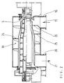
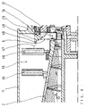
- the dewatering and drying device shown in Fig. 1 (“Centrifuge dryer”) has a solid bowl screw centrifuge in the example shown 1 known type.
- Solid bowl screw centrifuges can also be used for dewatering Suspensions, e.g. Slurries, suitable centrifuges, for example Sieve-jack screw centrifuges or 3-phase centrifuges are used in which a phase is to be dried.
- the "dewatering centrifuge” or “centrifuge” for short designated solid bowl screw centrifuge 1 has a rotating Drum 2, which is rotatably mounted on roller bearings 3 at its axial ends is.
- the drum 2 tapers conically at one or both ends and is on Its tapered end is provided with discharge openings 4 which define the discharge zone 5 forms for the pre-dewatered solid 6.
- the through a tube 7 inside suspension fed to the centrifuge 1, e.g. liquid sludge 8, is in the Centrifuge 1 due to the centrifugal force into a solid 6 and a clarified Liquid 9 separated from the other end of the drum shell 2 from the Centrifuge 1 is hosed into a separate housing 10, the centrate chute.
- the dryer surrounding the centrifuge 1 is replaced by an external one Dryer housing 11 and an interior surrounding the rotating drum 2 Housing 12 or by the drum 2 itself, as well as by the two End walls 13 and 14 formed.
- the drying gas 15 is by a Hot gas shaft 16 introduced tangentially into the dryer room 17, flows around the solid 6 dispersed in the form of particles, that of the impact cone 18 is deflected in the axial direction and transports the drying Solid particles in spiral tracks through the concentric annular space 19 to Output channel 20 of the dryer housing 11. From here flows with the dried solid particles loaded drying gas 21 by a not shown pneumatic delivery line to a solids separator and is there again separated into gas and solid aggregate.
- the perforated plate 22 can consist of a conical surface or from several sections with different cone angles, hole shapes, Slits, free opening cross sections or partial solid sheet sections be composed to achieve the effects mentioned.
- the baffle cone 18 and or the dryer housing 11 can also full or partial annular gaps 23 can be formed in order to prevent undesirable accumulations of solids to prevent.
- the flow plate 22 through which flow can flow can be a bowl-shaped, cylindrical or flat deviating from the cone Have shape or be composed of different shapes.
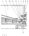
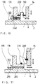
- Fig. 2 is a combined centrifuge dryer with built-in guide elements 25, 26 shown in the concentric annular space of the dryer.
- the centrifuge dryer is constructed from similar components and functions as in Fig. 1. Instead of the perforated plate 22, however, 19 are spiral in the dryer room Baffles 25, 26 installed, which concentrically concentrate the gas flow Force dryer room 19 and short-circuit flows between hot gas inlet 16 and prevent gas outlet 20.
- the baffle 26 may preferably have a smaller slope of its spiral shape than that in the axial direction arranged behind the baffle 26 baffles 25.
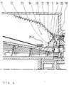
- Fig. 3 shows an enlarged view of the discharge zone 5 of a combined centrifuge dryer with two or more rotating cleaning blades 28, which clean the deflecting surface 29 of the impact cone 18 with each rotor revolution.
- the Pre-dewatered solid 6 is from the screw conveyor to the centrifuge 1 Sprayed edge 30 transported and there at high speed out of the rotor 2 thrown out.
- the solid particles bounce on the surface 29 of the Impact cone 18, are broken up into smaller particles and braked there.
- the decelerated particles fly at a greatly reduced speed and in Deflected in the axial direction as a conical solid spray into the Dryer room 19 and there are intensively flushed with hot gas and dried.
- the cleaning blades 28 are viewed in the direction of rotation behind the solids outlet openings 31 attached to the rotor and are exiting Solid 6 not sprayed. Should serve when very moist or sticky solid particles 6 on the deflection surface 29 some particles not are reflected and stick to the surface 29, they are from the subsequent rotating cleaning blades 28 torn off and in the Tumbled dryer room 19.
- the high peripheral speed of approx. 60m / s rotating blades 28 also exert a pressure on the surrounding hot gas 15a sucking and promoting effect, with the further consequence that the surrounding hot gas 15a the solid dust located in the dryer room 19 partially promotes in the drop zone 5.
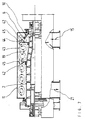
- Fig. 4 is the discharge zone 5 of a centrifugal dryer with a steeper angle of the impact cone 18, perforated gas guide plates 22 and rotating Blow blades 33 shown.
- the cleaning action of the puff blades 33 is not based on a scraping action Effect, but on the blowing effect of the intense gas flow 34 that flows out of the rotating nozzle 33 and onto the surface 29 to be cleaned of the impact cone 18 occurs at a flat angle.
- Gas production through the Bladder blade 33 is particularly increased by taking suitable measures, such as For example, large intake cross sections at the blade inlet 35, guide elements in the blade and directed blowing at the blade outlet.
- the deflection surface can also be coated with a suitable material be such as PTFE, enamel, ceramic, or other anti-adhesive acting materials.
- a suitable material be such as PTFE, enamel, ceramic, or other anti-adhesive acting materials.
- the surface 29 can also consist of a perforated surface exist and be ventilated.
- the discharge openings 4 of the centrifuge 1 have a conveying effect at their edges on the gas inside the interior 37 of the centrifuge 1. As a result of this Conveying effect from the interior 37 of the centrifuge 1 moist gas sucked out and drawn in hot, dry gas. This will moist solid 6 with the centrifuge 1 even before it is ejected long pre-dried.
- FIG. 6 shows a combination of a turbulence vane 40 for keeping the Dryer room 19 and a cleaning scoop 28 for cleaning the surface 29 of the impact cone 18 is shown.
- the turbulence vane 40 has one high peripheral speed and generates a strong swirl 41 of Drying gas in the dryer room 19. This does not flow through Dead zones avoided and the incoming drying gas 15 with the dispersed Particles mixed intensely.
- the cleaning scoop 28 can, as shown, scrape off part or all of the surface 29 of the impact cone or blow off.
- the blades 28 and or 40 can be rigid or oscillating on the rotor 2 be movably attached.
- rotating turbulence disks for generation are in the dryer room 19 of tubular vortex rollers 43 installed.
- the dryer housing 11 is without one fixed inner housing 12 formed, which in some embodiments the drum 2 envelops the centrifuge dryer.
- the concentric Dryer chamber 19 is therefore outside of a non-rotating cylinder wall and limited on the inside by the rapidly rotating centrifuge drum 2.
- the rotating one Surface of the drum 2 in connection with the rapidly rotating disks 42 induce in the dryer room 19 a series of turbulent vortex rollers rotating in themselves 43.
- These turbulence vortex rollers 43 are rotating Surfaces of the drum 2 and the disks 42 driven generate in overall cross-section a high degree of turbulence and even the Flow through the dryer chamber 19 in the circumferential direction.
- the high degree of turbulence the vortex rollers prevents deposits on the boundary walls of the Dryer housing 11, forcing an intimate mixing of drying gas and the dispersed solid particles and produces a high drying rate for the moist solid particles, combined with an extreme high water evaporation rate based on the dryer volume.
- the entering Hot gas 15 is rotating through the passage gaps 44 outside Discs 42 and through the toroidal turbulence vortex rollers in his axial movement smoothed over the entire circumference.
- rotating disks 42 can also be on the centrifuge drum 2
- Elements for generating turbulence rollers are used in the dryer, for example a radial blade ring, axial or radial feed wheels, Club arms or other suitable internals known per se.
- Blade rings 46 attached to generate a high degree of turbulence in the Dryer room 19 and for uniform axial conveyance and control of the Residence time of the drying gas laden with solids. In addition to these functions the blade rings 46 also cause agglomerates in the Dryer room 19.
- the surface 29 of the impact cone 18 consists of several geometrically composed smooth surfaces. At the impact zone 48 of the pre-dewatered dispersed solid 6, the surface consists of a flat Cone, to which a rounded surface contour 49 adjoins further outside. Due to the flat impact angle of the dispersed moist solid particles 6 on the smooth baffle cone 18 is divided into several smaller ones Particles 47 which favors reflection and further transport.
- the centrifuge dryer shown in Fig. 9 in turn consists of a Centrifuge, in the example shown from a solid bowl centrifuge 1 which is surrounded by an outer housing 11 of an atomizing dryer. Around the centrifuge drum 2, an inner housing 12 is arranged.
- the outer dryer housing 11 and the inner housing 12 form the concentric Dryer room 19 through which the drying gas 15 is passed.
- the Drying gas 15 is fed through the tangential hot gas shaft 16, detects in the region of the discharge zone 5 in the form of a dispersed Particle veil thrown off, dewatered solid, transports the Solid particles with increasing drying in spiral paths the dryer room 19 and reaches the outlet channel as a gas 21 laden with solid material 20.
- the water separated in the centrifuge 1 is in the centrate chute 10 derived.
- the outer dryer housing 11 is on the two end walls 13 and 14 sealed against the rapidly rotating centrifuge drum 2.
- the gap 190 of the rotary seals 160 is formed by the centrifuge drum 2 and the sealing ring 170, which, like the drum pedestals 210 on the base frame 220 is rigidly attached. By fastening the two, the sealing gap 190 forming active surfaces 2 and 170 on the same support 220 is the sealing gap 190 guided precisely and stably.
- the centrifuge drum 2 also remains Flow through the dryer room 19 with hot gas 15 through the given Suspension cold and does not expand, whereas hot gas 15 flowed through dryer housing 11 strong in the axial and radial directions expands.
- the displacement movements of the two housing end walls 13 and 14 are through a gas-tight flexible compensator 180 or an elastic membrane or a sliding link ring 300 opposite the rigidly attached Sealing ring 170 compensated so that the sealing gap 190 is not changed.
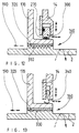
- Fig. 10 shows in detail a non-contact labyrinth seal for one Centrifuge dryer, with the sealing ring 170 rigidly attached to the frame 220 the axially and radially shifting dryer end wall 14 gas-tight connects a compensator 180.
- the flexible compensator 180 is e.g. by Tension straps 230 or other fasteners with both the sealing ring 170 and connected to the end wall 14 in a gastight manner.
- the sealing gap 190 between the tips 240 of the labyrinth seal and the rotating surface of the centrifuge drum 2 can be very narrow (0.3 - 0.5mm) be held, since the displacement movement of the end wall 14 is not on the Labyrinth seal is transferred.
- FIG 11 shows a non-contact rotary seal 160 in the form of a thread seal for a centrifuge dryer, e.g. in the dryer room to the right of the End wall 14 has a negative pressure.
- the sliding and sliding movements of the front wall 13 and 14 of the dryer during the heating up or cooling down phase of the dryer housing 11 compensated for a sheet metal ring 260, which is sealed by heat-resistant O-rings 270 is and both on the housing end wall 13 and 14 as well as rigid attached sealing ring 170 can slide.
- the threads 280 can also be used with a fluid barrier medium such as Water or sealing gas can be filled, which through the threads 280th is passed through.
- the moving dryer housing 11 is by the Setting slide ring 300 balanced in the gap.
- the sliding block 300 itself is due to heat-resistant O-rings both on the dryer end wall 14 and on rigidly attached sealing ring 170 slidably sealed.
- Fig. 13 shows a non-contact rotary seal 160 with flat grooves, which in a soft cylinder liner 320 made of plain bearing materials with a very narrow gap 190 rotates.
- the displacement movement of the end wall 13 or 14 of the dryer housing 11 is by a resilient in the radial and axial directions Sliding ring 340 balanced.
Landscapes
- Engineering & Computer Science (AREA)
- Mechanical Engineering (AREA)
- General Engineering & Computer Science (AREA)
- Life Sciences & Earth Sciences (AREA)
- Microbiology (AREA)
- Health & Medical Sciences (AREA)
- Molecular Biology (AREA)
- Drying Of Solid Materials (AREA)
- Centrifugal Separators (AREA)
- Treatment Of Sludge (AREA)
Applications Claiming Priority (3)
| Application Number | Priority Date | Filing Date | Title |
|---|---|---|---|
| DE19631605A DE19631605C1 (de) | 1996-08-05 | 1996-08-05 | Turbulenzschaufeln für Entwässerungseinrichtung |
| DE19631605 | 1996-08-05 | ||
| EP97915449A EP0916065B1 (fr) | 1996-08-05 | 1997-03-27 | Dispositif pour deshydrater et secher des suspensions |
Related Parent Applications (1)
| Application Number | Title | Priority Date | Filing Date |
|---|---|---|---|
| EP97915449A Division EP0916065B1 (fr) | 1996-08-05 | 1997-03-27 | Dispositif pour deshydrater et secher des suspensions |
Publications (2)
| Publication Number | Publication Date |
|---|---|
| EP0979984A2 true EP0979984A2 (fr) | 2000-02-16 |
| EP0979984A3 EP0979984A3 (fr) | 2001-09-19 |
Family
ID=7801851
Family Applications (2)
| Application Number | Title | Priority Date | Filing Date |
|---|---|---|---|
| EP99121798A Withdrawn EP0979984A3 (fr) | 1996-08-05 | 1997-03-27 | Dispositif pour déshydrater et sécher des suspensions |
| EP97915449A Expired - Lifetime EP0916065B1 (fr) | 1996-08-05 | 1997-03-27 | Dispositif pour deshydrater et secher des suspensions |
Family Applications After (1)
| Application Number | Title | Priority Date | Filing Date |
|---|---|---|---|
| EP97915449A Expired - Lifetime EP0916065B1 (fr) | 1996-08-05 | 1997-03-27 | Dispositif pour deshydrater et secher des suspensions |
Country Status (8)
| Country | Link |
|---|---|
| US (1) | US6618956B1 (fr) |
| EP (2) | EP0979984A3 (fr) |
| JP (1) | JP3215439B2 (fr) |
| AT (1) | ATE204638T1 (fr) |
| CA (1) | CA2262705A1 (fr) |
| DE (2) | DE19631605C1 (fr) |
| ES (1) | ES2163751T3 (fr) |
| WO (1) | WO1998005912A1 (fr) |
Cited By (3)
| Publication number | Priority date | Publication date | Assignee | Title |
|---|---|---|---|---|
| WO2002024341A1 (fr) * | 2000-09-22 | 2002-03-28 | Baker Hughes (Deutschland) Gmbh | Centrifugeuse pour le drainage mecanique et le sechage thermique de boues |
| WO2004051166A3 (fr) * | 2002-12-04 | 2004-09-02 | Baumann Schilp Lucia | Deshumidification, sechage et regulation de la grosseur de grains combines de matieres |
| EP3769847A1 (fr) * | 2019-07-26 | 2021-01-27 | Siebtechnik GmbH | Centrifugeuse-séchoir continue |
Families Citing this family (12)
| Publication number | Priority date | Publication date | Assignee | Title |
|---|---|---|---|---|
| DE102005023258A1 (de) * | 2004-11-16 | 2006-11-23 | Fan Separator Gmbh | Drehtrommel zur aeroben Erwärmung rieselfähiger Feststoffe |
| US7669348B2 (en) * | 2006-10-10 | 2010-03-02 | Rdp Company | Apparatus, method and system for treating sewage sludge |
| DE102011055190A1 (de) * | 2011-11-09 | 2013-05-16 | Fabian Rypacek | Eindicker |
| RU2625629C1 (ru) * | 2016-05-30 | 2017-07-17 | Федеральное государственное бюджетное образовательное учреждение высшего образования "Тамбовский государственный технический университет" ФГБОУ ВО "ТГТУ" | Сушилка для пастообразных материалов на полидисперсном инертном носителе |
| CN106721913A (zh) * | 2017-02-27 | 2017-05-31 | 山东农业大学 | 卧式块状软体食品脱水机 |
| RU2682794C1 (ru) * | 2017-10-25 | 2019-03-21 | Федеральное государственное бюджетное образовательное учреждение высшего образования "Тамбовский государственный технический университет" (ФГБОУ ВО "ТГТУ") | Установка для сушки дисперсных растительных материалов в полидисперсном слое инертных тел |
| RU2707022C1 (ru) * | 2018-12-20 | 2019-11-21 | федеральное государственное автономное образовательное учреждение высшего образования "Национальный исследовательский университет ИТМО" (Университет ИТМО) | Устройство для сушки суспензий |
| CN109796117A (zh) * | 2019-03-25 | 2019-05-24 | 江苏旭云物联信息科技有限公司 | 智能化控制三相分离机 |
| CN112386925B (zh) * | 2020-10-27 | 2021-12-14 | 湖南精诚制药机械有限公司 | 基于旋转式药品离心干燥设备 |
| CN114216306B (zh) * | 2021-11-09 | 2022-12-20 | 黑龙江中医药大学 | 一种中草药烘干罐 |
| CN116294521B (zh) * | 2023-05-17 | 2023-11-10 | 华北理工大学 | 一种矿粉球团烘干设备 |
| CN118500100A (zh) * | 2024-07-17 | 2024-08-16 | 山东万达环保科技有限公司 | 用于高活性氢氧化钙脱硫剂制备的脱水干燥装置 |
Citations (1)
| Publication number | Priority date | Publication date | Assignee | Title |
|---|---|---|---|---|
| DE4332799A1 (de) | 1993-09-27 | 1995-03-30 | Baumann Schilp Lucia | Verfahren und Vorrichtung zum Entwässern von Schlämmen |
Family Cites Families (11)
| Publication number | Priority date | Publication date | Assignee | Title |
|---|---|---|---|---|
| DE948497C (de) * | 1954-09-08 | 1956-08-30 | Krauss Maffei Ag | Kontinuierlich arbeitende Zentrifuge mit einer nachgeschalteten heissgas- oder heissdampfbetriebenen Trockeneinrichtung |
| US3194492A (en) * | 1962-06-28 | 1965-07-13 | Richard A Koffinke | Pressurized centrifuge |
| US3724091A (en) * | 1971-05-11 | 1973-04-03 | J Rousselet | Continuous production centrifuge |
| DE3329669A1 (de) * | 1983-08-17 | 1985-03-07 | Klöckner-Humboldt-Deutz AG, 5000 Köln | Zentrifuge, insbesondere vollmantel-schneckenzentrifuge zur feststoff-fluessigkeitsstrennung von schlaemmen |
| CH663273A5 (en) * | 1984-12-18 | 1987-11-30 | Fershan Holding S A | Method of continuous drying of a powdered substance and apparatus for implementing it |
| US4692248A (en) * | 1986-02-26 | 1987-09-08 | The Dehydro Corporation | Drum filter with resin bound particulate filter media |
| US5085443A (en) * | 1990-05-29 | 1992-02-04 | Amoco Corporation | Labyrinth seal |
| DE4106248A1 (de) * | 1991-02-28 | 1992-09-03 | Werner & Pfleiderer | Zentrifugaltrockner zur trennung von oberflaechenwasser von kunststoffgranulat |
| ATE120536T1 (de) * | 1991-06-25 | 1995-04-15 | Baumann Schilp Lucia | Verfahren und vorrichtung zum entwässern von schlämmen. |
| US5321898A (en) * | 1992-06-19 | 1994-06-21 | Decanter Machine, Inc. | Centrifugal screen bowl dryer |
| SE509400C2 (sv) * | 1996-01-02 | 1999-01-25 | Noxon Ab | Dekanteringscentrifug |
-
1996
- 1996-08-05 DE DE19631605A patent/DE19631605C1/de not_active Expired - Fee Related
-
1997
- 1997-03-27 EP EP99121798A patent/EP0979984A3/fr not_active Withdrawn
- 1997-03-27 JP JP50749798A patent/JP3215439B2/ja not_active Expired - Fee Related
- 1997-03-27 AT AT97915449T patent/ATE204638T1/de not_active IP Right Cessation
- 1997-03-27 US US09/242,038 patent/US6618956B1/en not_active Expired - Fee Related
- 1997-03-27 WO PCT/EP1997/001570 patent/WO1998005912A1/fr active Application Filing
- 1997-03-27 CA CA002262705A patent/CA2262705A1/fr not_active Abandoned
- 1997-03-27 ES ES97915449T patent/ES2163751T3/es not_active Expired - Lifetime
- 1997-03-27 EP EP97915449A patent/EP0916065B1/fr not_active Expired - Lifetime
- 1997-03-27 DE DE59704388T patent/DE59704388D1/de not_active Expired - Fee Related
Patent Citations (1)
| Publication number | Priority date | Publication date | Assignee | Title |
|---|---|---|---|---|
| DE4332799A1 (de) | 1993-09-27 | 1995-03-30 | Baumann Schilp Lucia | Verfahren und Vorrichtung zum Entwässern von Schlämmen |
Cited By (4)
| Publication number | Priority date | Publication date | Assignee | Title |
|---|---|---|---|---|
| WO2002024341A1 (fr) * | 2000-09-22 | 2002-03-28 | Baker Hughes (Deutschland) Gmbh | Centrifugeuse pour le drainage mecanique et le sechage thermique de boues |
| US6823605B2 (en) | 2000-09-22 | 2004-11-30 | Baker Hughes Incorporated | Centrifuge for mechanical draining and thermal drying of sludges |
| WO2004051166A3 (fr) * | 2002-12-04 | 2004-09-02 | Baumann Schilp Lucia | Deshumidification, sechage et regulation de la grosseur de grains combines de matieres |
| EP3769847A1 (fr) * | 2019-07-26 | 2021-01-27 | Siebtechnik GmbH | Centrifugeuse-séchoir continue |
Also Published As
| Publication number | Publication date |
|---|---|
| JP2000507693A (ja) | 2000-06-20 |
| US6618956B1 (en) | 2003-09-16 |
| DE19631605C1 (de) | 1997-10-02 |
| DE59704388D1 (de) | 2001-09-27 |
| EP0916065B1 (fr) | 2001-08-22 |
| ES2163751T3 (es) | 2002-02-01 |
| ATE204638T1 (de) | 2001-09-15 |
| JP3215439B2 (ja) | 2001-10-09 |
| EP0979984A3 (fr) | 2001-09-19 |
| CA2262705A1 (fr) | 1998-02-12 |
| EP0916065A1 (fr) | 1999-05-19 |
| WO1998005912A1 (fr) | 1998-02-12 |
Similar Documents
| Publication | Publication Date | Title |
|---|---|---|
| EP0591299B1 (fr) | Procede et dispositif de deshydratation de boues de curage | |
| EP0979984A2 (fr) | Dispositif pour déshydrater et sécher des suspensions | |
| EP0046569B1 (fr) | Procédé et appareil pour mélanger des solides avec des liquides | |
| EP3154703B1 (fr) | Centrifugeuse à vis à bol plein | |
| DE2228682A1 (de) | Vorrichtung zum trocknen von fliessfaehigen stoffen | |
| EP0298914B1 (fr) | Dispositif de séchage par atomisation pour la fabrication de poudres, agglomérates ou similaires | |
| EP0638365B2 (fr) | Procédé et dispositif pour séparer des matières solides à grains fins en deux fractions granulométriques | |
| DE2622565B2 (de) | Verfahren zum Trocknen von insbesondere feinkörnigen Feststoffpartikeln in einem gasförmigen Träger- und Trocknungsstrom und Vorrichtung zur Durchführung des Verfahrens | |
| DE69104715T2 (de) | Dekanterzentrifuge. | |
| DE10139413A1 (de) | Vorrichtung zum Mischen und Dispergieren von pulverförmigen feinst- bis grobkörnigen Substanzen mit mindestens einer Flüssigkeit | |
| DE1519676A1 (de) | Vorrichtung und Verfahren zur Feinverteilung von Fluessigkeit mit rotierendem Verteilerkoerper | |
| DE2834491C2 (de) | Siebzentrifuge mit gekrümmten Siebtaschen | |
| WO2004051166A2 (fr) | Deshumidification, sechage et regulation de la grosseur de grains combines de matieres | |
| DE60107448T2 (de) | Zentrifuge zur mechanischen entwässerung und thermischen trocknung von schlämmen | |
| DE4332799C2 (de) | Verfahren und Vorrichtung zum Entwässern von Schlämmen | |
| AT503390B1 (de) | Vorrichtung zur trocknung nassen schüttfähigen gutes, vorzugsweise von kunststoffteilchen | |
| DE4038954C2 (de) | Verfahren zum Abtransportieren und Zentrifuge zur Durchführung des Verfahrens | |
| DE3006438C2 (de) | Verfahren zum Beschicken eines kontinuierlich arbeitenden Mischers und kontinuierlich arbeitender Mischer | |
| DE3024853A1 (de) | Windsichtvorrichtung | |
| DE967459C (de) | Drehtrommeltrockner | |
| DE1963264C3 (de) | Vorrichtung zum Zerkleinern eines Materials | |
| EP3480542A1 (fr) | Dispositif de séparation permettant de séparer un mélange d'un matériau solide et d'un fluide | |
| EP0638521A1 (fr) | Dispositif pour la déshydratation de boues de curage | |
| DE3043730A1 (de) | Zentrifugalstromtrockner | |
| DE2634513C3 (de) | Vorrichtung zum Trocknen disperser Stoffe in einer zylinderförmigen Kammer |
Legal Events
| Date | Code | Title | Description |
|---|---|---|---|
| PUAI | Public reference made under article 153(3) epc to a published international application that has entered the european phase |
Free format text: ORIGINAL CODE: 0009012 |
|
| 17P | Request for examination filed |
Effective date: 19991103 |
|
| AC | Divisional application: reference to earlier application |
Ref document number: 916065 Country of ref document: EP |
|
| AK | Designated contracting states |
Kind code of ref document: A2 Designated state(s): AT BE CH DE DK ES FR GB IT LI NL PT SE |
|
| PUAL | Search report despatched |
Free format text: ORIGINAL CODE: 0009013 |
|
| AK | Designated contracting states |
Kind code of ref document: A3 Designated state(s): AT BE CH DE DK ES FR GB IT LI NL PT SE |
|
| AKX | Designation fees paid |
Free format text: AT BE CH DE DK ES FR GB IT LI NL PT SE |
|
| STAA | Information on the status of an ep patent application or granted ep patent |
Free format text: STATUS: THE APPLICATION IS DEEMED TO BE WITHDRAWN |
|
| 18D | Application deemed to be withdrawn |
Effective date: 20020220 |