EP0979984A2 - Apparatus for dewatering and drying of suspensions - Google Patents
Apparatus for dewatering and drying of suspensions Download PDFInfo
- Publication number
- EP0979984A2 EP0979984A2 EP99121798A EP99121798A EP0979984A2 EP 0979984 A2 EP0979984 A2 EP 0979984A2 EP 99121798 A EP99121798 A EP 99121798A EP 99121798 A EP99121798 A EP 99121798A EP 0979984 A2 EP0979984 A2 EP 0979984A2
- Authority
- EP
- European Patent Office
- Prior art keywords
- dryer
- centrifuge
- blades
- gas
- turbulence
- Prior art date
- Legal status (The legal status is an assumption and is not a legal conclusion. Google has not performed a legal analysis and makes no representation as to the accuracy of the status listed.)
- Withdrawn
Links
Images


Classifications
-
- B—PERFORMING OPERATIONS; TRANSPORTING
- B04—CENTRIFUGAL APPARATUS OR MACHINES FOR CARRYING-OUT PHYSICAL OR CHEMICAL PROCESSES
- B04B—CENTRIFUGES
- B04B1/00—Centrifuges with rotary bowls provided with solid jackets for separating predominantly liquid mixtures with or without solid particles
- B04B1/20—Centrifuges with rotary bowls provided with solid jackets for separating predominantly liquid mixtures with or without solid particles discharging solid particles from the bowl by a conveying screw coaxial with the bowl axis and rotating relatively to the bowl
-
- B—PERFORMING OPERATIONS; TRANSPORTING
- B04—CENTRIFUGAL APPARATUS OR MACHINES FOR CARRYING-OUT PHYSICAL OR CHEMICAL PROCESSES
- B04B—CENTRIFUGES
- B04B15/00—Other accessories for centrifuges
- B04B15/12—Other accessories for centrifuges for drying or washing the separated solid particles
-
- F—MECHANICAL ENGINEERING; LIGHTING; HEATING; WEAPONS; BLASTING
- F26—DRYING
- F26B—DRYING SOLID MATERIALS OR OBJECTS BY REMOVING LIQUID THEREFROM
- F26B17/00—Machines or apparatus for drying materials in loose, plastic, or fluidised form, e.g. granules, staple fibres, with progressive movement
- F26B17/10—Machines or apparatus for drying materials in loose, plastic, or fluidised form, e.g. granules, staple fibres, with progressive movement with movement performed by fluid currents, e.g. issuing from a nozzle, e.g. pneumatic, flash, vortex or entrainment dryers
- F26B17/107—Machines or apparatus for drying materials in loose, plastic, or fluidised form, e.g. granules, staple fibres, with progressive movement with movement performed by fluid currents, e.g. issuing from a nozzle, e.g. pneumatic, flash, vortex or entrainment dryers pneumatically inducing within the drying enclosure a curved flow path, e.g. circular, spiral, helical; Cyclone or Vortex dryers
-
- F—MECHANICAL ENGINEERING; LIGHTING; HEATING; WEAPONS; BLASTING
- F26—DRYING
- F26B—DRYING SOLID MATERIALS OR OBJECTS BY REMOVING LIQUID THEREFROM
- F26B17/00—Machines or apparatus for drying materials in loose, plastic, or fluidised form, e.g. granules, staple fibres, with progressive movement
- F26B17/24—Machines or apparatus for drying materials in loose, plastic, or fluidised form, e.g. granules, staple fibres, with progressive movement with movement performed by shooting or throwing the materials, e.g. after which the materials are subject to impact
-
- F—MECHANICAL ENGINEERING; LIGHTING; HEATING; WEAPONS; BLASTING
- F26—DRYING
- F26B—DRYING SOLID MATERIALS OR OBJECTS BY REMOVING LIQUID THEREFROM
- F26B3/00—Drying solid materials or objects by processes involving the application of heat
- F26B3/02—Drying solid materials or objects by processes involving the application of heat by convection, i.e. heat being conveyed from a heat source to the materials or objects to be dried by a gas or vapour, e.g. air
- F26B3/10—Drying solid materials or objects by processes involving the application of heat by convection, i.e. heat being conveyed from a heat source to the materials or objects to be dried by a gas or vapour, e.g. air the gas or vapour carrying the materials or objects to be dried with it
- F26B3/12—Drying solid materials or objects by processes involving the application of heat by convection, i.e. heat being conveyed from a heat source to the materials or objects to be dried by a gas or vapour, e.g. air the gas or vapour carrying the materials or objects to be dried with it in the form of a spray, i.e. sprayed or dispersed emulsions or suspensions
-
- F—MECHANICAL ENGINEERING; LIGHTING; HEATING; WEAPONS; BLASTING
- F26—DRYING
- F26B—DRYING SOLID MATERIALS OR OBJECTS BY REMOVING LIQUID THEREFROM
- F26B5/00—Drying solid materials or objects by processes not involving the application of heat
- F26B5/08—Drying solid materials or objects by processes not involving the application of heat by centrifugal treatment
-
- F—MECHANICAL ENGINEERING; LIGHTING; HEATING; WEAPONS; BLASTING
- F26—DRYING
- F26B—DRYING SOLID MATERIALS OR OBJECTS BY REMOVING LIQUID THEREFROM
- F26B7/00—Drying solid materials or objects by processes using a combination of processes not covered by a single one of groups F26B3/00 and F26B5/00
Definitions
- the invention relates to a device for dewatering and drying Suspensions according to the preamble of claim 1.
- Such Drainage and drying device is known from DE-A4332799.
- the dewatering and drying device with high Speed at the centrifuge ejection preferably one Solid bowl screw centrifuge, radially hosed moist solid particles in the Size 0.3 - 3mm by suitable means, for example deflection surfaces or by suitable gas flow in the axial direction of the centrifuge and deflected by the Gas flow on a spiral trajectory in the drying room.
- suitable means for example deflection surfaces or by suitable gas flow in the axial direction of the centrifuge and deflected by the Gas flow on a spiral trajectory in the drying room.
- the sprayed solid particles from the drying gas with high Rinsed relative speed and dried The drying room is a concentric annulus. It is made from the outer dryer housing, the internal rotating drum shell of the centrifuge or an inner that Drum surrounding housing and the two housing end walls are formed.
- a disadvantage of the known dewatering and drying device concerns Deflection surfaces for the solid particles thrown out of the rotating centrifuge. Despite using wall scratches on the rotating Centrifuge drum can be attached in case of poor mechanical Pre-drainage of the suspensions through the centrifuge or with very sticky and moist solid particles deposits and incrustations on the deflection surfaces, but also in the dryer housing or in the subsequent equipment (washer, Cyclone) occur. This causes malfunctions and business interruptions in the continuous drying operation, which is associated with economic disadvantages is. So far, attempts have been made to suspend such difficult-to-drain suspensions Adding additives before centrifuging in their moisture and To change adhesive behavior favorably. However, the cost of this is considerable.
- the object of the invention in contrast, is in a drainage and Drying device of the type mentioned at the outset, malfunctions, caused by deposits and incrustations of solid particles avoid constructive measures.
- the invention provides for mechanically stimulated turbulence Drying gas a fine dispersion of the pre-dewatered solid generate, to distribute the dispersed solid particles in the drying gas well and to blow away any build-up of incrustation.
- concentration of dispersed damp small particles in the dryer room should be even and be low and the relative velocity of the hot gas to the particles should be as large as possible in order to dry the moisture very quickly Ensure solid particles in flight.
- Outside on derotating Centrifuge drums are elements that protrude into the dryer room attached, which fuel the gas flow and for strong turbulence in the Close to the incrustation-prone surfaces in the dryer room or at the Deflect surfaces.
- the surfaces of the effective space walls in the dryer can Polished or anti-adhesive coated to help prevent incrustation his. Due to the guide and guide plates installed in the dryer room, the Flow of the hot gas is influenced in a targeted manner in order to achieve an even gas distribution cause to avoid dead spaces and intensive contact of the hot gas to ensure with the moist solid particles. Perforated gas Walls are also suitable, incrustations due to moist sticky Prevent solid particles if the sticky ones are caused by the inflowing hot gas Particles are kept away from the walls until the particles on their Surface have dried sufficiently and then with a lower moisture content lose their tendency to adhere. Especially with organic sewage sludge a pronounced glue phase is the tendency to adhesion in certain Moisture areas particularly large and must fly in a split second be overcome.
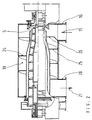
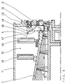
- the dewatering and drying device shown in Fig. 1 (“Centrifuge dryer”) has a solid bowl screw centrifuge in the example shown 1 known type.
- Solid bowl screw centrifuges can also be used for dewatering Suspensions, e.g. Slurries, suitable centrifuges, for example Sieve-jack screw centrifuges or 3-phase centrifuges are used in which a phase is to be dried.
- the "dewatering centrifuge” or “centrifuge” for short designated solid bowl screw centrifuge 1 has a rotating Drum 2, which is rotatably mounted on roller bearings 3 at its axial ends is.
- the drum 2 tapers conically at one or both ends and is on Its tapered end is provided with discharge openings 4 which define the discharge zone 5 forms for the pre-dewatered solid 6.
- the through a tube 7 inside suspension fed to the centrifuge 1, e.g. liquid sludge 8, is in the Centrifuge 1 due to the centrifugal force into a solid 6 and a clarified Liquid 9 separated from the other end of the drum shell 2 from the Centrifuge 1 is hosed into a separate housing 10, the centrate chute.
- the dryer surrounding the centrifuge 1 is replaced by an external one Dryer housing 11 and an interior surrounding the rotating drum 2 Housing 12 or by the drum 2 itself, as well as by the two End walls 13 and 14 formed.
- the drying gas 15 is by a Hot gas shaft 16 introduced tangentially into the dryer room 17, flows around the solid 6 dispersed in the form of particles, that of the impact cone 18 is deflected in the axial direction and transports the drying Solid particles in spiral tracks through the concentric annular space 19 to Output channel 20 of the dryer housing 11. From here flows with the dried solid particles loaded drying gas 21 by a not shown pneumatic delivery line to a solids separator and is there again separated into gas and solid aggregate.
- the perforated plate 22 can consist of a conical surface or from several sections with different cone angles, hole shapes, Slits, free opening cross sections or partial solid sheet sections be composed to achieve the effects mentioned.
- the baffle cone 18 and or the dryer housing 11 can also full or partial annular gaps 23 can be formed in order to prevent undesirable accumulations of solids to prevent.
- the flow plate 22 through which flow can flow can be a bowl-shaped, cylindrical or flat deviating from the cone Have shape or be composed of different shapes.
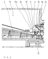
- Fig. 2 is a combined centrifuge dryer with built-in guide elements 25, 26 shown in the concentric annular space of the dryer.
- the centrifuge dryer is constructed from similar components and functions as in Fig. 1. Instead of the perforated plate 22, however, 19 are spiral in the dryer room Baffles 25, 26 installed, which concentrically concentrate the gas flow Force dryer room 19 and short-circuit flows between hot gas inlet 16 and prevent gas outlet 20.
- the baffle 26 may preferably have a smaller slope of its spiral shape than that in the axial direction arranged behind the baffle 26 baffles 25.
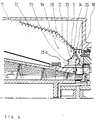
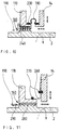
- Fig. 3 shows an enlarged view of the discharge zone 5 of a combined centrifuge dryer with two or more rotating cleaning blades 28, which clean the deflecting surface 29 of the impact cone 18 with each rotor revolution.
- the Pre-dewatered solid 6 is from the screw conveyor to the centrifuge 1 Sprayed edge 30 transported and there at high speed out of the rotor 2 thrown out.
- the solid particles bounce on the surface 29 of the Impact cone 18, are broken up into smaller particles and braked there.
- the decelerated particles fly at a greatly reduced speed and in Deflected in the axial direction as a conical solid spray into the Dryer room 19 and there are intensively flushed with hot gas and dried.
- the cleaning blades 28 are viewed in the direction of rotation behind the solids outlet openings 31 attached to the rotor and are exiting Solid 6 not sprayed. Should serve when very moist or sticky solid particles 6 on the deflection surface 29 some particles not are reflected and stick to the surface 29, they are from the subsequent rotating cleaning blades 28 torn off and in the Tumbled dryer room 19.
- the high peripheral speed of approx. 60m / s rotating blades 28 also exert a pressure on the surrounding hot gas 15a sucking and promoting effect, with the further consequence that the surrounding hot gas 15a the solid dust located in the dryer room 19 partially promotes in the drop zone 5.
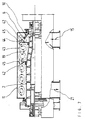
- Fig. 4 is the discharge zone 5 of a centrifugal dryer with a steeper angle of the impact cone 18, perforated gas guide plates 22 and rotating Blow blades 33 shown.
- the cleaning action of the puff blades 33 is not based on a scraping action Effect, but on the blowing effect of the intense gas flow 34 that flows out of the rotating nozzle 33 and onto the surface 29 to be cleaned of the impact cone 18 occurs at a flat angle.
- Gas production through the Bladder blade 33 is particularly increased by taking suitable measures, such as For example, large intake cross sections at the blade inlet 35, guide elements in the blade and directed blowing at the blade outlet.
- the deflection surface can also be coated with a suitable material be such as PTFE, enamel, ceramic, or other anti-adhesive acting materials.
- a suitable material be such as PTFE, enamel, ceramic, or other anti-adhesive acting materials.
- the surface 29 can also consist of a perforated surface exist and be ventilated.
- the discharge openings 4 of the centrifuge 1 have a conveying effect at their edges on the gas inside the interior 37 of the centrifuge 1. As a result of this Conveying effect from the interior 37 of the centrifuge 1 moist gas sucked out and drawn in hot, dry gas. This will moist solid 6 with the centrifuge 1 even before it is ejected long pre-dried.
- FIG. 6 shows a combination of a turbulence vane 40 for keeping the Dryer room 19 and a cleaning scoop 28 for cleaning the surface 29 of the impact cone 18 is shown.
- the turbulence vane 40 has one high peripheral speed and generates a strong swirl 41 of Drying gas in the dryer room 19. This does not flow through Dead zones avoided and the incoming drying gas 15 with the dispersed Particles mixed intensely.
- the cleaning scoop 28 can, as shown, scrape off part or all of the surface 29 of the impact cone or blow off.
- the blades 28 and or 40 can be rigid or oscillating on the rotor 2 be movably attached.
- rotating turbulence disks for generation are in the dryer room 19 of tubular vortex rollers 43 installed.
- the dryer housing 11 is without one fixed inner housing 12 formed, which in some embodiments the drum 2 envelops the centrifuge dryer.
- the concentric Dryer chamber 19 is therefore outside of a non-rotating cylinder wall and limited on the inside by the rapidly rotating centrifuge drum 2.
- the rotating one Surface of the drum 2 in connection with the rapidly rotating disks 42 induce in the dryer room 19 a series of turbulent vortex rollers rotating in themselves 43.
- These turbulence vortex rollers 43 are rotating Surfaces of the drum 2 and the disks 42 driven generate in overall cross-section a high degree of turbulence and even the Flow through the dryer chamber 19 in the circumferential direction.
- the high degree of turbulence the vortex rollers prevents deposits on the boundary walls of the Dryer housing 11, forcing an intimate mixing of drying gas and the dispersed solid particles and produces a high drying rate for the moist solid particles, combined with an extreme high water evaporation rate based on the dryer volume.
- the entering Hot gas 15 is rotating through the passage gaps 44 outside Discs 42 and through the toroidal turbulence vortex rollers in his axial movement smoothed over the entire circumference.
- rotating disks 42 can also be on the centrifuge drum 2
- Elements for generating turbulence rollers are used in the dryer, for example a radial blade ring, axial or radial feed wheels, Club arms or other suitable internals known per se.
- Blade rings 46 attached to generate a high degree of turbulence in the Dryer room 19 and for uniform axial conveyance and control of the Residence time of the drying gas laden with solids. In addition to these functions the blade rings 46 also cause agglomerates in the Dryer room 19.
- the surface 29 of the impact cone 18 consists of several geometrically composed smooth surfaces. At the impact zone 48 of the pre-dewatered dispersed solid 6, the surface consists of a flat Cone, to which a rounded surface contour 49 adjoins further outside. Due to the flat impact angle of the dispersed moist solid particles 6 on the smooth baffle cone 18 is divided into several smaller ones Particles 47 which favors reflection and further transport.
- the centrifuge dryer shown in Fig. 9 in turn consists of a Centrifuge, in the example shown from a solid bowl centrifuge 1 which is surrounded by an outer housing 11 of an atomizing dryer. Around the centrifuge drum 2, an inner housing 12 is arranged.
- the outer dryer housing 11 and the inner housing 12 form the concentric Dryer room 19 through which the drying gas 15 is passed.
- the Drying gas 15 is fed through the tangential hot gas shaft 16, detects in the region of the discharge zone 5 in the form of a dispersed Particle veil thrown off, dewatered solid, transports the Solid particles with increasing drying in spiral paths the dryer room 19 and reaches the outlet channel as a gas 21 laden with solid material 20.
- the water separated in the centrifuge 1 is in the centrate chute 10 derived.
- the outer dryer housing 11 is on the two end walls 13 and 14 sealed against the rapidly rotating centrifuge drum 2.
- the gap 190 of the rotary seals 160 is formed by the centrifuge drum 2 and the sealing ring 170, which, like the drum pedestals 210 on the base frame 220 is rigidly attached. By fastening the two, the sealing gap 190 forming active surfaces 2 and 170 on the same support 220 is the sealing gap 190 guided precisely and stably.
- the centrifuge drum 2 also remains Flow through the dryer room 19 with hot gas 15 through the given Suspension cold and does not expand, whereas hot gas 15 flowed through dryer housing 11 strong in the axial and radial directions expands.
- the displacement movements of the two housing end walls 13 and 14 are through a gas-tight flexible compensator 180 or an elastic membrane or a sliding link ring 300 opposite the rigidly attached Sealing ring 170 compensated so that the sealing gap 190 is not changed.
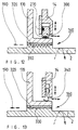
- Fig. 10 shows in detail a non-contact labyrinth seal for one Centrifuge dryer, with the sealing ring 170 rigidly attached to the frame 220 the axially and radially shifting dryer end wall 14 gas-tight connects a compensator 180.
- the flexible compensator 180 is e.g. by Tension straps 230 or other fasteners with both the sealing ring 170 and connected to the end wall 14 in a gastight manner.
- the sealing gap 190 between the tips 240 of the labyrinth seal and the rotating surface of the centrifuge drum 2 can be very narrow (0.3 - 0.5mm) be held, since the displacement movement of the end wall 14 is not on the Labyrinth seal is transferred.
- FIG 11 shows a non-contact rotary seal 160 in the form of a thread seal for a centrifuge dryer, e.g. in the dryer room to the right of the End wall 14 has a negative pressure.
- the sliding and sliding movements of the front wall 13 and 14 of the dryer during the heating up or cooling down phase of the dryer housing 11 compensated for a sheet metal ring 260, which is sealed by heat-resistant O-rings 270 is and both on the housing end wall 13 and 14 as well as rigid attached sealing ring 170 can slide.
- the threads 280 can also be used with a fluid barrier medium such as Water or sealing gas can be filled, which through the threads 280th is passed through.
- the moving dryer housing 11 is by the Setting slide ring 300 balanced in the gap.
- the sliding block 300 itself is due to heat-resistant O-rings both on the dryer end wall 14 and on rigidly attached sealing ring 170 slidably sealed.
- Fig. 13 shows a non-contact rotary seal 160 with flat grooves, which in a soft cylinder liner 320 made of plain bearing materials with a very narrow gap 190 rotates.
- the displacement movement of the end wall 13 or 14 of the dryer housing 11 is by a resilient in the radial and axial directions Sliding ring 340 balanced.
Landscapes
- Engineering & Computer Science (AREA)
- Mechanical Engineering (AREA)
- General Engineering & Computer Science (AREA)
- Life Sciences & Earth Sciences (AREA)
- Microbiology (AREA)
- Health & Medical Sciences (AREA)
- Molecular Biology (AREA)
- Drying Of Solid Materials (AREA)
- Treatment Of Sludge (AREA)
- Centrifugal Separators (AREA)
Abstract
Description
Die Erfindung bezieht sich auf eine Vorrichtung zum Entwässern und Trocknen von
Suspensionen gemäß dem Oberbegriff des Anspruchs 1. Eine derartige
Entwässerungs- und Trocknungsvorrichtung ist aus der DE-A4332799 bekannt.The invention relates to a device for dewatering and drying
Suspensions according to the preamble of
Bei der bekannten Entwässerungs- und Trocknungsvorrichtung werden die mit hoher Geschwindigkeit am Auswurf der Zentrifuge, vorzugsweise einer Vollmantelschneckenzentrifuge, radial abgespritzten feuchten Feststoffpartikeln in der Größe 0,3 - 3mm durch geeignete Mittel, beispielsweise Umlenkflächen oder durch geeignete Gasströmung in Achsrichtung der Zentrifuge umgelenkt und von der Gasströmung auf einer spiralförmigen Flugbahn im Trocknungsraum geführt. Hier werden die abgespritzten Feststoffpartikeln vom Trocknungsgas mit hoher Relativgeschwindigkeit umspült und getrocknet. Der Trocknungsraum ist ein konzentrischer Ringraum. Er wird aus dem äußeren Trocknergehäuse, dem innenliegenden rotierenden Trommelmantel der Zentrifuge oder einem inneren, die Trommel umgebenden Gehäuse und den beiden Gehäusestirnwänden gebildet.In the known dewatering and drying device with high Speed at the centrifuge ejection, preferably one Solid bowl screw centrifuge, radially hosed moist solid particles in the Size 0.3 - 3mm by suitable means, for example deflection surfaces or by suitable gas flow in the axial direction of the centrifuge and deflected by the Gas flow on a spiral trajectory in the drying room. Here the sprayed solid particles from the drying gas with high Rinsed relative speed and dried. The drying room is a concentric annulus. It is made from the outer dryer housing, the internal rotating drum shell of the centrifuge or an inner that Drum surrounding housing and the two housing end walls are formed.
Ein Nachteil der bekannten Entwässerungs- und Trocknungsvorrichtung betrifft die Umlenkflächen für die aus der rotierenden Zentrifuge abgeschleuderten Feststoff-Partikeln. Trotz Verwendung von Wandkratzern, die an der rotierenden Zentrifugentrommel befestigt sind, können bei schlechter mechanischer Vorentwässerung der Suspensionen durch die Zentrifuge oder bei sehr klebrigen und feuchten Feststoff-Partikeln Anlagerungen und Verkrustungen an den Umlenkflächen, aber auch im Trocknergehäuse oder in den nachfolgenden Apparaturen (Wäscher, Zyklon) auftreten. Hierdurch entstehen Störungen und Betriebsunterbrechungen im kontinuierlichen Trocknungsbetrieb, was mit wirtschaftlichen Nachteilen verbunden ist. Bislang versucht man, solche schwierig zu entwässernden Suspensionen durch Zumischen von Zusatzstoffen vor dem Zentrifugieren in ihrem Feuchtigkeits- und Klebeverhalten günstig zu verändern. Die Kosten hierfür sind jedoch beträchtlich.A disadvantage of the known dewatering and drying device concerns Deflection surfaces for the solid particles thrown out of the rotating centrifuge. Despite using wall scratches on the rotating Centrifuge drum can be attached in case of poor mechanical Pre-drainage of the suspensions through the centrifuge or with very sticky and moist solid particles deposits and incrustations on the deflection surfaces, but also in the dryer housing or in the subsequent equipment (washer, Cyclone) occur. This causes malfunctions and business interruptions in the continuous drying operation, which is associated with economic disadvantages is. So far, attempts have been made to suspend such difficult-to-drain suspensions Adding additives before centrifuging in their moisture and To change adhesive behavior favorably. However, the cost of this is considerable.
Die Aufgabe der Erfindung besteht demgegenüber darin, bei einer Entwässerungs- und Trocknungsvorrichtung der eingangs erwähnten Art Betriebsstörungen, verursacht durch Anlagerungen und Verkrustungen von Feststoff-Partikeln, durch konstruktive Maßnahmen zu vermeiden.The object of the invention, in contrast, is in a drainage and Drying device of the type mentioned at the outset, malfunctions, caused by deposits and incrustations of solid particles avoid constructive measures.
Diese Aufgabe wird erfindungsgemäß durch die kennzeichnenden Merkmale des
Anspruchs 1 gelöst.This object is achieved by the characterizing features of
Vorteilhafte Ausgestaltungen der Erfindung sind in den Unteransprüchen angegeben.Advantageous embodiments of the invention are specified in the subclaims.
Die Erfindung sieht vor, durch mechanisch angefachte Turbulenzen des Trocknungsgases eine feine Dispergierung des vorentwässerten Feststoffes zu erzeugen, die dispergierten Feststoffpartikeln im Trocknungsgas gut zu verteilen und sich eventuell aufbauende Verkrustungsschichten wegzublasen. Die Konzentration der dispergierten feuchten kleinen Partikeln im Trocknerraum soll gleichmäßig und niedrig sein und die Relativgeschwindigkeit des heißen Gases gegenüber den Partikeln soll dabei möglichst groß sein, um ein sehr rasches Abtrocknen der feuchten Feststoffpartikeln im Fluge sicherzustellen. Außen an derotierenden Zentrifugentrommel sind hierzu in den Trocknerraum hineinragende Elemente befestigt, welche die Gasströmung anfachen und für eine starke Turbulenz in der Nähe der verkrustungsgefährdeten Oberflächen im Trocknerraum oder an den Umlenkflächen sorgen. Die Oberflächen der Wirkraumwände im Trockner können zur Unterstützung der Verkrustungsverhinderung poliert oder antiadhäsiv beschichtet sein. Durch die in den Trocknerraum eingebauten Leit- und Führungsbleche wird die Strömung des Heißgases gezielt beeinflußt, um eine gleichmäßige Gasverteilung zu bewirken, um Toträume zu vermeiden und einen intensiven Kontakt des Heißgases mit den feuchten Feststoffpartikeln zu gewährleisten. Gasdurchströmte, perforierte Wände sind ebenfalls geeignet, Verkrustungen durch feuchte klebrige Feststoffpartikeln zu verhindern, wenn durch das einströmende Heißgas die klebrigen Partikeln solange von den Wänden ferngehalten werden, bis die Partikeln an ihrer Oberfläche genügend abgetrocknet sind und dann bei niedrigerem Feuchtigkeitsgehalt ihre Adhäsionsneigung verlieren. Insbesondere bei organischen Klärschlämmen mit einer ausgeprägten Leimphase ist die Adhäsionsneigung in bestimmten Feuchtigkeitsbereichen besonders groß und muß in Sekundenbruchteilen im Fluge überwunden werden.The invention provides for mechanically stimulated turbulence Drying gas a fine dispersion of the pre-dewatered solid generate, to distribute the dispersed solid particles in the drying gas well and to blow away any build-up of incrustation. The concentration of dispersed damp small particles in the dryer room should be even and be low and the relative velocity of the hot gas to the particles should be as large as possible in order to dry the moisture very quickly Ensure solid particles in flight. Outside on derotating Centrifuge drums are elements that protrude into the dryer room attached, which fuel the gas flow and for strong turbulence in the Close to the incrustation-prone surfaces in the dryer room or at the Deflect surfaces. The surfaces of the effective space walls in the dryer can Polished or anti-adhesive coated to help prevent incrustation his. Due to the guide and guide plates installed in the dryer room, the Flow of the hot gas is influenced in a targeted manner in order to achieve an even gas distribution cause to avoid dead spaces and intensive contact of the hot gas to ensure with the moist solid particles. Perforated gas Walls are also suitable, incrustations due to moist sticky Prevent solid particles if the sticky ones are caused by the inflowing hot gas Particles are kept away from the walls until the particles on their Surface have dried sufficiently and then with a lower moisture content lose their tendency to adhere. Especially with organic sewage sludge a pronounced glue phase is the tendency to adhesion in certain Moisture areas particularly large and must fly in a split second be overcome.
Weitere Vorteile der Erfindung sind die Vermeidung von Verkrustungen und Anbackungen auch bei schwierig zu entwässernden Schlämmen. Hierdurch wird der Einsatz- und Anwendungsbereich der erfindungsgemäßen Vorrichtung auch auf Produkte ausgedehnt, die nach der mechanischen Entwässerung zu einem Feststoff führen, der sehr stark klebt oder einen sehr hohen Feuchtigkeitsgehalt aufweist. Auch durch Anbackungen hervorgerufene Betriebsunterbrechnungen durch zu feuchte mechanische Vorentwässerung in der Zentrifuge und die damit verbundenen Kosten werden vermieden.Further advantages of the invention are the avoidance of incrustations and Caking even with sludge that is difficult to dewater. This will Use and application of the device according to the invention also on Products expanded to a solid after mechanical drainage lead that sticks very well or has a very high moisture content having. Business interruptions caused by caking due to too moist mechanical pre-dewatering in the centrifuge and the result associated costs are avoided.
Weitere Einzelheiten, Vorteile und Merkmale der Erfindung werden mit den Ausführungsbeispielen anhand von Zeichnungen näher erläutert.Further details, advantages and features of the invention are described in the Embodiments explained in more detail with reference to drawings.
Es zeigen:
- Fig. 1
- eine Entwässerungs- und Trocknungsvorrichtung (im folgenden als "Zentrifugentrockner" bezeichnet) mit perforierten Gasführungsblechen im Längsschnitt;
- Fig. 2
- einen Zentrifugentrockner mit Leitblechen im Trocknerraum im Längsschnitt;
- Fig. 3
- die Dispergierzone eines Zentrifugentrockners mit rotierenden Reinigungsschaufeln für die Umlenkflächen der dispergierten Partikeln;
- Fig. 4
- die Dispergierzone eines Zentrifugentrockners mit rotierenden Turbulenzschaufeln zum Freihalten der Trocknerwände;
- Fig. 5
- eine Kombination von Reinigungs- und Turbulenzschaufeln zur Verhinderung von Verkrustungen im Trocknerinnenraum und Leitungen;
- Fig. 6
- eine Kombination von Turbulenz- und Transportschaufeln zum Freihalten des Trocknerinnenraums;
- Fig. 7
- rotierende Turbulenzscheiben im Trocknerraum zur Erzeugung von Turbulenzwirbelwalzen für die Redispergierung;
- Fig. 8
- Umlenkflächen zur besseren Dispergierung und breiteren Verteilung der vorentwässerten feuchten Feststoffpartikeln;
- Fig. 9
- einen Zentrifugentrockner mit Gehäusedichtung im Längsschnitt;
- Fig. 10
- eine berührungsfreie Labyrinthdichtung für einen Zentrifugentrockner;
- Fig. 11
- eine berührungsfreie Gewinde-Förderdichtung für einen Zentrifugentrockner;
- Fig. 12
- eineberührungsfreie Gewinde-Förderdichtung mit Spitzengewinde, und
- Fig. 13
- eine berührungsfreie Dichtung mit Flachnuten.
- Fig. 1
- a dewatering and drying device (hereinafter referred to as "centrifuge dryer") with perforated gas guide plates in longitudinal section;
- Fig. 2
- a centrifuge dryer with baffles in the dryer room in longitudinal section;
- Fig. 3
- the dispersion zone of a centrifuge dryer with rotating cleaning blades for the deflection surfaces of the dispersed particles;
- Fig. 4
- the dispersion zone of a centrifugal dryer with rotating turbulence blades to keep the dryer walls clear;
- Fig. 5
- a combination of cleaning and turbulence blades to prevent incrustations in the dryer interior and pipes;
- Fig. 6
- a combination of turbulence and transport blades to keep the dryer interior clear;
- Fig. 7
- rotating turbulence disks in the dryer room for the production of turbulence vortex rolls for redispersion;
- Fig. 8
- Deflection surfaces for better dispersion and wider distribution of the pre-dewatered moist solid particles;
- Fig. 9
- a centrifuge dryer with a housing seal in longitudinal section;
- Fig. 10
- a non-contact labyrinth seal for a centrifuge dryer;
- Fig. 11
- a non-contact threaded conveyor seal for a centrifuge dryer;
- Fig. 12
- a non-contact thread conveyor seal with a tip thread, and
- Fig. 13
- a non-contact seal with flat grooves.
Die in Fig. 1 dargestellte Entwässerungs- und Trocknungsvorrichtung ("Zentrifugentrockner") weist im dargestellten Beispielfall eine Vollmantel-Schneckenzentrifuge 1 bekannter Bauart auf. Anstelle der dargestellten Vollmantel-Schneckenzentrifuge können auch andere, für die Entwässerung von Suspensionen, z.B. Schlämmen, geeignete Zentrifugen, beispielsweise Siebmantel-Schneckenzentrifugen oder 3-Phasen-Trennzentrifugen verwendet werden, bei der eine Phase getrocknet werden soll.The dewatering and drying device shown in Fig. 1 ("Centrifuge dryer") has a solid bowl screw centrifuge in the example shown 1 known type. Instead of the shown Solid bowl screw centrifuges can also be used for dewatering Suspensions, e.g. Slurries, suitable centrifuges, for example Sieve-jack screw centrifuges or 3-phase centrifuges are used in which a phase is to be dried.
Die nachstehend als "Entwässerungszentrifuge" oder kurz "Zentrifuge"
bezeichnete Vollmantel-Schneckenzentrifuge 1 weist eine rotierende
Trommel 2 auf, welche an ihren axialen Enden auf Wälzlagern 3 drehbar gelagert
ist. Die Trommel 2 verjüngt sich konisch an einem oder beiden Enden und ist an
Ihrem verjüngten Ende mit Abwurföffnungen 4 versehen, welche die Abwurfzone
5 für den vorentwässerten Feststoff 6 bildet. Die durch ein Rohr 7 in das Innere
der Zentrifuge 1 zugeführte Suspension, z.B. flüssiger Schlamm 8, wird in der
Zentrifuge 1 infolge der Fliehkraft in einen Feststoff 6 und eine geklärte
Flüssigkeit 9 getrennt, die am anderen Ende des Trommelmantels 2 aus der
Zentrifuge 1 in ein separates Gehäuse 10, der Zentratschurre, abgespritzt wird.The "dewatering centrifuge" or "centrifuge" for short
designated solid
Der die Zentrifuge 1 direkt umgebende Trockner wird durch ein äußeres
Trocknergehäuse 11 und ein die rotierende Trommel 2 umgebendes inneres
Gehäuse 12 oder auch durch die Trommel 2 selbst, sowie durch die beiden
Stirnwände 13 und 14 gebildet. Das Trocknungsgas 15 wird durch einen
Heißgasschacht 16 in den Trocknerraum 17 beispielsweise tangential eingeleitet,
umspült den in Form von Partikeln dispergierten Feststoff 6, der vom Prallkegel
18 in axialer Richtung umgelenkt wird und transportiert die trocknenden
Feststoffpartikeln in Spiralbahnen durch den konzentrischen Ringraum 19 zum
Ausgangskanal 20 des Trocknergehäuses 11. Von hier aus strömt das mit den
getrockneten Feststoffpartikeln beladene Trocknungsgas 21 durch eine nicht
dargestellte pneumatische Förderleitung zu einem Feststoffabscheider und wird
dort wieder in Gas und Feststoffhaufwerk getrennt.The dryer surrounding the
Um das eintretende heiße Trocknungsgas 15 im konzentrischen Ringraum 19
gleichmäßig zu verteilen und mit den, vom Prallkegel 18 umgelenkten und
abgebremsten Feststoffpartikeln innig zu vermischen, ist ein beispielsweise
kegelförmig ausgebildetes Lochblech 22 eingebaut, das vom Heißgas 15
durchströmt wird. Das Lochblech 22 kann aus einer Kegelfläche bestehen oder
aus mehreren Abschnitten mit unterschiedlichen Kegelwinkeln, Lochformen,
Schlitzen, freien Öffnungsquerschnitten oder teilweisen Vollblechabschnitten
zusammengesetzt sein, um die genannten Wirkungen zu erzielen. Zwischen dem
Lochblech 22, dem Prallkegel 18 und oder dem Trocknergehäuse 11 können auch
volle oder teilweise Ringspalte 23 ausgebildet sein, um unerwünschte Feststoffansammlungen
zu verhindern. Auch das durchströmbare Verteilungsblech 22
kann eine vom Kegel abweichende schüsselförmige, zylinderförmige oder ebene
Form besitzen oder aus verschiedenen Formen zusammengesetzt sein.Around the entering hot drying
In Fig. 2 ist ein kombinierter Zentrifugentrockner mit eingebauten Leitelementen
25, 26 im konzentrischen Ringraum des Trockners dargestellt. Der Zentrifugentrockner
ist aus ähnlichen Bauteilen und Funktionen wie in Fig. 1 aufgebaut.
Anstelle des Lochbleches 22 sind jedoch im Trocknerraum 19 spiralförmige
Leitbleche 25, 26 eingebaut, welche die Gasströmung im konzentrischen
Trocknerraum 19 zwangsführen und Kurzschlußströmungen zwischen Heißgaseintritt
16 und Gasausgang 20 verhindern. Das Leitblech 26 kann vorzugsweise
eine geringere Steigung seiner Spiralform aufweisen als die in Axialrichtung
hinter dem Leitblech 26 angeordneten Leitbleche 25. Bei geeigneter Ausbildung
des Leitbleches 26 (welches im Eintrittsbereich des Heißgases 15 angeordnet ist)
ist es möglich, die Anzahl der Leitbleche 25, welche sich in der Darstellung nach
Fig. 2 über nahezu die gesamte Länge des Trocknergehäuses 11 erstrecken, zu
verringern oder auf die Leitbleche 25 vollständig zu verzichten. Das beispielsweise
tangential eintretende Heißgas 15 (auch als "Trocknungsgas" bezeichnet)
wird im Bereich der Abwurfzone 5 des dispergierten, feuchten Feststoffes 6
durch ein Leitblech 26 zunächst nahezu vollständig in Umfangrichtung herumgeführt,
wo es mit Feststoffpartikeln durchsetzt wird. Das feststoffbeladene
Trocknungsgas 15 wird durch die spiralförmigen Leitbleche 25 in Spiralbahnen
zum Trocknerausgang 20 geführt wird. Durch die Leitbleche 25 und 26 werden
nichtdurchströmte Totzonen im Trocknerraum 19 vermieden und überall eine
vorgegebene Mindest-Transportgeschwindigkeit des Trocknungsgases 15 sowie
eine gleiche Verweilzeit der dispergierten Feststoffpartikeln erzwungen.In Fig. 2 is a combined centrifuge dryer with built-in
Fig. 3 zeigt in Vergrößerung die Abwurfzone 5 eines kombinierten Zentrifugentrockners
mit zwei oder mehreren rotierenden Reinigungsschaufeln 28, welche
die Umlenkfläche 29 des Prallkegels 18 bei jeder Rotorumdrehung reinigen. Der
vorentwässerte Feststoff 6 wird von der Förderschnecke der Zentrifuge 1 zur
Abspritzkante 30 transportiert und dort mit hoher Geschwindigkeit aus dem Rotor
2 herausgeschleudert. Die Feststoffpartikeln prallen auf der Oberfläche 29 des
Prallkegels 18 auf, werden dort in kleinere Partikeln zerteilt und abgebremst. Die
abgebremsten Partikeln fliegen mit stark verminderter Geschwindigkeit und in
Achsrichtung hin abgelenkt als kegelförmiger Feststoffsprühnebel in den
Trocknerraum 19 und werden dort intensiv mit Heißgas umspült und getrocknet.
Die Reinigungsschaufeln 28 sind in Drehrichtung betrachtet hinter den Feststoffauslaßöffnungen
31 am Rotor befestigt und werden vom austretenden
Feststoff 6 nicht bespritzt. Sollten beim Aufschlag von sehr feuchten oder
klebrigen Feststoffpartikeln 6 auf der Umlenkfläche 29 einige Partikeln nicht
reflektiert werden und auf der Oberfläche 29 haften bleiben, werden sie von den
nachfolgenden rotierenden Reinigungsschaufeln 28 losgerissen und in den
Trocknerraum 19 geschleudert. Die mit hoher Umfangsgeschwindigkeit von ca.
60m/s rotierenden Schaufeln 28 üben auch auf das umgebende Heißgas 15a eine
ansaugende und fördernde Wirkung aus, mit der weiteren Folge, daß das
umgebende Heißgas 15a den im Trocknerraum 19 befindlichen Feststoffstaub
teilweise in die Abwurfzone 5 fördert. Das von den Schafeln 28 angesaugte,
staubhaltige Heißgas 15a wird zusammen mit den abgeschabten Feststoffpartikeln
je nach Gestaltung der Führungsflächen von den Reinigungsschaufeln radial oder
kegelförmig in den Trocknerraum 19 herausgeschleudert. Zur Intensivierung der
Gasförderung können an den Schaufeln Ansaug- und Leitbleche 32 angebracht
werden.Fig. 3 shows an enlarged view of the
In Fig. 4 ist die Abwurfzone 5 eines Zentrifugentrockners mit steilerem Winkel
des Prallkegels 18, perforierten Gasführungsblechen 22 und rotierenden
Blasschaufeln 33 dargestellt. Im Gegensatz zu den Reinigungsschaufeln 28 in Fig.
3 beruht die reinigende Wirkung der Blassehaufeln 33 nicht auf einer abkratzenden
Wirkung, sondern auf der Blasewirkung der intensiven Gasströmung 34, die
aus der rotierenden Düse 33 ausströmt und auf die zu reinigende Oberfläche 29
des Prallkegels 18 unter flachen Winkel auftritt. Die Gasförderung durch die
Blaseschaufel 33 ist besonders gesteigert durch geeignete Maßnahmen, wie
beispielsweise große Ansaugquerschnitte am Schaufeleintritt 35, Leitelemente in
der Schaufel und gerichtetes Ausblasen am Schaufelaustritt. Durch die Sogwirkung
des staubhaltigen Heißgases 15a an der Schaufel-Eintrittsseite 35 und
durch das ausströmende Heißgas 36 aus den perforierten Gasführungsflächen 22
wird die Gasströmung im Trocknerraum 19 mit den dispergierten Feststoffpartikeln
6 von den Wänden des Trocknergehäuses 11 ferngehalten und mehr
nach innen verlagen. Der von der Abspritzkante 30 der Zentrifugentrommel 2
herausfliegende Feststoff 6 gelangt noch vor dem Aufschlagen auf die Oberfläche
29 des Prallkegels 18 in den Einflußbereich des Heißgases 15a, welches
staubhaltig ist und durch die Blaseschaufel 33 gefördert wird. Hierdurch werden
die Feststoffpartikeln an ihrer Oberfläche abgetrocknet sowie mit trockenem
Feststoffstaub beschichtet (coating), so daß sie noch vor der Berührung mit der
Oberfläche 29 ihre Klebeneigung verlieren. Um die Klebeneigung weiter herabzusetzen,
kann die Umlenkfläche auch mit einem geeigneten Material beschichtet
sein, wie beispielsweise PTFE, Emaille, Keramik, oder andere antiadhäsiv
wirkende Materialien. Die Oberfläche 29 kann auch aus einer perforierten Fläche
bestehen und hinterlüftet sein.In Fig. 4 is the
In Fig. 5 ist eine Kombination einer rotierenden Reinigungsschaufel 28 und einer
Blaseschaufel 33, zusammenwirkend mit einem perforierten Gasführungsblech 22,
dargestellt. Die Reinigung der Oberfläche 29 des Prallkegels 18 erfolgt durch
einen rotierenden Kratzschaber 38 in Verbindung mit der blasenden Wirkung des
angesaugten Heißgases. Der austretende Blasestrahl 34 ist nicht nur auf die
Oberfläche des Prallkegels gerichtet, sondern bläst auch tangential auf das
perforierte Gasführungsblech 22. Die ansaugende Seitenwand 39 für das Heißgas
kann gegenüber der Umfangrichtung leicht schräg angestellt oder mit Öffnungen
versehen sein, um von der Blaseschaufel 33 mehr Gas ansaugen zu können. Die
Abwurföffnungen 4 der Zentrifuge 1 üben an ihren Rändern eine Förderwirkung
auf das Gas innerhalb des Innenraums 37 der Zentrifuge 1 aus. Infolge dieser
Förderwirkung wird aus dem Innenraum 37 der Zentrifuge 1 feuchtes Gas
herausgesaugt und heißes, trockenes Gas hineingezogen. Hierdurch wird der
feuchte Feststoff 6 bereits vor dem Abwurf im Wendelgang der Zentrifuge 1 mit
großer Verweilzeit vorgetrocknet. 5 is a combination of a
In Fig. 6 ist eine Kombination einer Turbulenzschaufel 40 zum Freihalten des
Trocknerraumes 19 und einer Reinigungsschaufel 28 zur Reinigung der Oberfläche
29 des Prallkegels 18 dargestellt. Die Turbulenzschaufel 40 besitzt eine
hohe Umfangsgeschwindigkeit und erzeugt eine starke Verwirbelung 41 des
Trocknungsgases im Trocknerraum 19. Hierdurch werden nichtdurchströmte
Totzonen vermieden und das eintretende Trocknungsgas 15 mit den dispergierten
Partikeln intensiv vermischt. Die Reinigungsschaufel 28 kann, wie dargestellt,
einen Teil oder die gesamte Oberfläche 29 des Prallkegels abkratzen oder
abblasen. Die Schaufeln 28 und oder 40 können am Rotor 2 starr oder pendelnd
beweglich befestigt sein.6 shows a combination of a
In Fig. 7 sind im Trocknerraum 19 rotierende Turbulenzscheiben zur Erzeugung
von Tubulenzwirbelwalzen 43 eingebaut. Das Trocknergehäuse 11 ist ohne ein
feststehendes Innengehäuse 12 ausgebildet, welches bei einigen Ausführungsformen
des Zentrifugentrockners die Trommel 2 umhüllt. Der konzentrische
Trocknerraum 19 wird daher außen von einer nichtrotierenden Zylinderwand und
innen von der schnell rotierenden Zentrifugentrommel 2 begrenzt. Die rotierende
Oberfläche der Trommel 2 in Verbindung mit den rasch rotierenden Scheiben 42
induzieren im Trocknerraum 19 eine Reihe von in sich kreisenden Turbulenzwirbelwalzen
43. Diese Turbulenzwirbelwalzen 43 werden von den rotierenden
Oberflächen der Trommel 2 und der Scheiben 42 angetrieben, erzeugen im
gesamten Querschnitt einen hohen Turbulenzgrad und vergleichmäßigen die
Durchströmung des Trocknerraumes 19 in Umfangrichtung. Der hohe Turbulenzgrad
der Wirbelwalzen verhindert Ablagerungen an den Begrenzungswänden des
Trocknergehäuses 11, erzwingt eine innige Durchmischung von Trocknungsgas
und den dispergierten Feststoffpartikeln und erzeugt eine hohe Trocknungsgeschwindigkeit
für die feuchten Feststoffpartikeln, verbunden mit einer extrem
hohen Wasserverdampfungsrate bezogen auf das Trocknervolumen. Das eintretende
Heißgas 15 wird durch die Durchtrittsspalte 44 außerhalb der rotierenden
Scheiben 42 und durch die torusförmigen Turbulenzwirbelwalzen in seiner
axialen Bewegung am gesamten Umfang vergleichmäßigt. Anstelle von
rotierenden Scheiben 42 können an der Zentrifugentrommel 2 auch andere
Elemente zur Erzeugung von Turbulenzwalzen im Trockner eingesetzt werden,
beispielsweise ein radialer Schaufelkranz, axiale oder radiale Förderräder,
Schlägerarme oder andere an sich bekannte geeignete Einbauten.In Fig. 7, rotating turbulence disks for generation are in the
In Fig. 8 sind an der rotierenden Zentrifugentrommel 2 außen ein oder mehrere
Schaufelkränze 46 angebracht zur Erzeugung eines hohen Turbulenzgrades im
Trocknerraum 19 und zur gleichmäßigen axialen Förderung und Steuerung der
Verweilzeit des feststoffbeladenen Trocknungsgases. Neben diesen Funktionen
bewirken die Schaufelkränze 46 auch eine Zerteilung von Agglomeraten im
Trocknerraum 19. Die Oberfläche 29 des Prallkegels 18 besteht aus mehreren
geometrisch zusammengesetzten glatten Flächen. An der Aufprallzone 48 des
vorentwässerten dispergierten Feststoffes 6 besteht die Fläche aus einem flachen
Kegel, an den sich weiter außen eine gerundete Oberflächenkontur 49 anschließt.
Durch den flachen Aufprallwinkel der dispergierten feuchten Feststoffpartikeln 6
auf den glatten Prallkegel 18 wird trotz der Zerteilung in mehrere kleinere
Partikeln 47 deren Reflexion und Weitertransport begünstigt. Die meist
erwünschte stärkere Umlenkung in axiale Flugrichtung erfolgt weiter außen durch
das Gleiten auf der gerundeten Oberflächenkontur 49 des Prallkegels 18. Durch
das zusätzliche Gleiten der zerteilten Partikeln wird deren Einschuß-geschwindigkeit
in den Trocknerraum 19 zusätzlich reduziert und damit die Gefahr von
Anbackungen an den Wänden des Trocknergehäuses 11 verringert.8, one or more are on the outside of the
Der in Fig. 9 dargestellte Zentrifugentrockner besteht wiederum aus einer
Zentrifuge, im dargestellten Beispiel aus einer Vollmantelschneckenzentrifuge 1
die von einem äußeren Gehäuse 11 eines Zerstäubungstrockners umhüllt ist. Um
die Zentrifugentrommel 2 ist ein inneres Gehäuse 12 angeordnet.The centrifuge dryer shown in Fig. 9 in turn consists of a
Centrifuge, in the example shown from a
Das äußere Trocknergehäuse 11 und das innere Gehäuse 12 bilden den konzentrischen
Trocknerraum 19, durch den das Trocknungsgas 15 geleitet wird. Das
Trocknungsgas 15 wird durch den tangentialen Heißgasschacht 16 zugeführt,
erfaßt im Bereich der Abwurfzone 5 den in Form eines dispergierten
Partikelschleiers abgeworfenen, entwässerten Feststoff, transportiert die
Feststoffpartikeln unter zunehmender Trocknung in spiralförmigen Bahnen durch
den Trocknerraum 19 und gelangt als feststoftbeladenes Gas 21 zum Ausgangskanal
20. Das in der Zentrifuge 1 abgetrennte Wasser wird in der Zentratschurre
10 abgeleitet.The
Das äußere Trocknergehäuse 11 ist an den beiden Stirnwänden 13 und 14
gegenüber der schnell rotierenden Zentrifugentrommel 2 abgedichtet. Der Spalt
190 der Drehdichtungen 160 wird gebildet von der Zentrifugentrommel 2 und
dem Dichtring 170, der ebenso wie die Trommel-Lagerböcke 210 am Grundrahmen
220 starr befestigt ist. Durch die Befestigung der beiden, den Dichtspalt
190 bildenden Wirkflächen 2 und 170 am gleichen Träger 220 ist der Dichtspalt
190 exakt und stabil geführt. Die Zentrifugentrommel 2 bleibt auch beim
Durchströmen des Trocknerraumes 19 mit Heißgas 15 durch die aufgegebene
Suspension kalt und dehnt sich nicht aus, wohingegen das mit Heißgas 15
durchströmte Trocknergehäuse 11 sich in axialer und radialer Richtung stark
ausdehnt.The
Die Verschiebebewegungen der beiden Gehäusestirnwände 13 und 14 werden
durch einen gasdichten flexiblen Kompensator 180 oder eine elastische Membran
oder einen verschiebbaren Kulissenring 300 gegenüber dem starr befestigten
Dichtring 170 ausgeglichen, so daß der Dichtspalt 190 nicht verändert wird.The displacement movements of the two
Fig. 10 zeigt im Detail eine berührungsfreie Labyrinthdichtung für einen
Zentrifugentrockner, die den starr am Rahmen 220 befestigten Dichtring 170 mit
der sich axial und radial verschiebenden Trocknerstirnwand 14 gasdicht durch
einen Kompensator 180 verbindet. Der flexible Kompensator 180 ist z.B. durch
Spannbänder 230 oder andere Befestigungsmittel sowohl mit dem Dichtring 170
als auch mit der Stirnwand 14 gasdicht verbunden.Fig. 10 shows in detail a non-contact labyrinth seal for one
Centrifuge dryer, with the sealing
Der Dichtspalt 190 zwischen den Spitzen 240 der Labyrinthdichtung und der
rotierenden Oberfläche der Zentrifugentrommel 2 kann sehr eng (0,3 - 0,5mm)
gehalten werden, da die Verschiebebewegung der Stirnwand 14 nicht auf die
Labyrinthdichtung übertragen wird. The sealing
Alle nichtrotierenden Teile sind rechtsschraffiert, alle rotierenden Teile sind linksschraffiert.All non-rotating parts are hatched right, all rotating parts are hatched left.
Fig. 11 zeigt eine berührungsfreie Drehdichtung 160 in Form einer Gewindedichtung
für einen Zentrifugentrockner, der z.B. im Trocknerraum rechts von der
Stirnwand 14 einen Unterdruck aufweist.11 shows a
Die Gleit- und Verschiebebewegungen der Stirnwand 13 bzw. 14 des Trockners
während der Aufheiz- oder Abkühlphase des Trocknergehäuses 11 werden durch
einen Blechring 260 ausgeglichen, der durch hitzefeste O-Ringe 270 abgedichtet
ist und sowohl an der Gehäusestirnwand 13 bzw. 14 wie auch am starr
befestigten Dichtring 170 gleiten kann. Der enge Dichtspalt 190 der als Gewindeförderdichtung
ausgebildeten Drehdichtung 160 bewirkt durch die Gewindegänge
280 in der Oberfläche der Zentrifugentrommel 2 eine dem Unterdruck im
Trockner entgegenwirkende Förderwirkung und einen Gas-Gegendruck, der das
Eindringen von Falschluft in den Trocknerraum 19 verhindert. Die Gewindegänge
280 können auch mit einem fluiden Sperrmedium wie beispielsweise
Wasser oder Sperrgas gefüllt werden, welches durch die Gewindegänge 280
hindurchgeleitet wird.The sliding and sliding movements of the
Fig. 12 zeigt eine berührungsfreie Drehdichtung 160 mit Spitzengewinde 310, das
mit engem Spalt 190 innerhalb einer weichen Zylinderfläche 320 rotiert. Die
Förderwirkung der Gewindedichtung gleicht den herrschenden Unterdruck im
Trockner aus. Das sich verschiebende Trocknergehäuse 11 wird durch den
Kulissen-Gleitring 300 im Spalt ausgeglichen. Der Kulissen-Gleitring 300 selbst
ist durch hitzefeste O-Ringe sowohl an der Trocknerstirnwand 14 wie auch am
starr befestigten Dichtring 170 verschiebbar abgedichtet.12 shows a
Fig. 13 zeigt eine berührungsfreie Drehdichtung 160 mit Flachnuten, die in einer
weichen Zylinderbüchse 320 aus Gleitlagerwerkstoffen mit sehr engem Spalt 190
rotiert. Die Verschiebebewegung der Stirnwand 13 bzw. 14 des Trocknergehäuses
11 wird durch einen in radialer und axialer Richtung federnden
Gleitring 340 ausgeglichen.Fig. 13 shows a
Claims (44)
Applications Claiming Priority (3)
| Application Number | Priority Date | Filing Date | Title |
|---|---|---|---|
| DE19631605 | 1996-08-05 | ||
| DE19631605A DE19631605C1 (en) | 1996-08-05 | 1996-08-05 | Sludge de-watering and drying assembly |
| EP97915449A EP0916065B1 (en) | 1996-08-05 | 1997-03-27 | Device for dewatering and drying suspensions |
Related Parent Applications (1)
| Application Number | Title | Priority Date | Filing Date |
|---|---|---|---|
| EP97915449A Division EP0916065B1 (en) | 1996-08-05 | 1997-03-27 | Device for dewatering and drying suspensions |
Publications (2)
| Publication Number | Publication Date |
|---|---|
| EP0979984A2 true EP0979984A2 (en) | 2000-02-16 |
| EP0979984A3 EP0979984A3 (en) | 2001-09-19 |
Family
ID=7801851
Family Applications (2)
| Application Number | Title | Priority Date | Filing Date |
|---|---|---|---|
| EP97915449A Expired - Lifetime EP0916065B1 (en) | 1996-08-05 | 1997-03-27 | Device for dewatering and drying suspensions |
| EP99121798A Withdrawn EP0979984A3 (en) | 1996-08-05 | 1997-03-27 | Apparatus for dewatering and drying of suspensions |
Family Applications Before (1)
| Application Number | Title | Priority Date | Filing Date |
|---|---|---|---|
| EP97915449A Expired - Lifetime EP0916065B1 (en) | 1996-08-05 | 1997-03-27 | Device for dewatering and drying suspensions |
Country Status (8)
| Country | Link |
|---|---|
| US (1) | US6618956B1 (en) |
| EP (2) | EP0916065B1 (en) |
| JP (1) | JP3215439B2 (en) |
| AT (1) | ATE204638T1 (en) |
| CA (1) | CA2262705A1 (en) |
| DE (2) | DE19631605C1 (en) |
| ES (1) | ES2163751T3 (en) |
| WO (1) | WO1998005912A1 (en) |
Cited By (3)
| Publication number | Priority date | Publication date | Assignee | Title |
|---|---|---|---|---|
| WO2002024341A1 (en) * | 2000-09-22 | 2002-03-28 | Baker Hughes (Deutschland) Gmbh | Centrifuge for mechanical draining and thermal drying of sludges |
| WO2004051166A3 (en) * | 2002-12-04 | 2004-09-02 | Baumann Schilp Lucia | Combined dewatering, drying and control of particle size of solids |
| EP3769847A1 (en) * | 2019-07-26 | 2021-01-27 | Siebtechnik GmbH | Continuous drying centrifuge |
Families Citing this family (14)
| Publication number | Priority date | Publication date | Assignee | Title |
|---|---|---|---|---|
| USD524825S1 (en) * | 2003-04-05 | 2006-07-11 | Varco I/P, Inc. | Centrifuge support |
| DE102005023258A1 (en) * | 2004-11-16 | 2006-11-23 | Fan Separator Gmbh | Rotary drum for aerobic heating of free-flowing solids |
| US7669348B2 (en) * | 2006-10-10 | 2010-03-02 | Rdp Company | Apparatus, method and system for treating sewage sludge |
| DE102011055190A1 (en) * | 2011-11-09 | 2013-05-16 | Fabian Rypacek | thickener |
| RU2625629C1 (en) * | 2016-05-30 | 2017-07-17 | Федеральное государственное бюджетное образовательное учреждение высшего образования "Тамбовский государственный технический университет" ФГБОУ ВО "ТГТУ" | Dryer for pasty materials on polydisperson inert carrier |
| CN106721913A (en) * | 2017-02-27 | 2017-05-31 | 山东农业大学 | Horizontal block soft body food dewaterer |
| RU2682794C1 (en) * | 2017-10-25 | 2019-03-21 | Федеральное государственное бюджетное образовательное учреждение высшего образования "Тамбовский государственный технический университет" (ФГБОУ ВО "ТГТУ") | Unit for drying disperse plant materials in polydisperse layer of inert bodies |
| RU2707022C1 (en) * | 2018-12-20 | 2019-11-21 | федеральное государственное автономное образовательное учреждение высшего образования "Национальный исследовательский университет ИТМО" (Университет ИТМО) | Device for suspensions drying |
| CN109796117A (en) * | 2019-03-25 | 2019-05-24 | 江苏旭云物联信息科技有限公司 | Intelligentized control method three-phase separator |
| CN112386925B (en) * | 2020-10-27 | 2021-12-14 | 湖南精诚制药机械有限公司 | Based on rotation type medicine centrifugation drying equipment |
| CN114216306B (en) * | 2021-11-09 | 2022-12-20 | 黑龙江中医药大学 | A drying jar of Chinese herbal medicine |
| CN116294521B (en) * | 2023-05-17 | 2023-11-10 | 华北理工大学 | A kind of mineral powder pellet drying equipment |
| CN118500100B (en) * | 2024-07-17 | 2024-11-08 | 山东万达环保科技有限公司 | Dehydration and drying device for the preparation of highly active calcium hydroxide desulfurizer |
| CN120309139B (en) * | 2025-03-13 | 2025-10-24 | 枣庄市汉森造纸数控设备有限公司 | A dehydration device based on papermaking process |
Citations (1)
| Publication number | Priority date | Publication date | Assignee | Title |
|---|---|---|---|---|
| DE4332799A1 (en) | 1993-09-27 | 1995-03-30 | Baumann Schilp Lucia | Process and apparatus for sludge dewatering |
Family Cites Families (11)
| Publication number | Priority date | Publication date | Assignee | Title |
|---|---|---|---|---|
| DE948497C (en) * | 1954-09-08 | 1956-08-30 | Krauss Maffei Ag | Continuously operating centrifuge with a downstream hot gas or hot steam operated drying device |
| US3194492A (en) * | 1962-06-28 | 1965-07-13 | Richard A Koffinke | Pressurized centrifuge |
| US3724091A (en) * | 1971-05-11 | 1973-04-03 | J Rousselet | Continuous production centrifuge |
| DE3329669A1 (en) * | 1983-08-17 | 1985-03-07 | Klöckner-Humboldt-Deutz AG, 5000 Köln | CENTRIFUGE, ESPECIALLY FULL-COVERED SNAIL CENTRIFUGE FOR SOLID-LIQUID SEPARATION OF SLUDGE |
| CH663273A5 (en) * | 1984-12-18 | 1987-11-30 | Fershan Holding S A | Method of continuous drying of a powdered substance and apparatus for implementing it |
| US4692248A (en) * | 1986-02-26 | 1987-09-08 | The Dehydro Corporation | Drum filter with resin bound particulate filter media |
| US5085443A (en) * | 1990-05-29 | 1992-02-04 | Amoco Corporation | Labyrinth seal |
| DE4106248A1 (en) * | 1991-02-28 | 1992-09-03 | Werner & Pfleiderer | CENTRIFUGAL DRYER FOR SEPARATING SURFACE WATER FROM PLASTIC GRANULES |
| ATE120536T1 (en) * | 1991-06-25 | 1995-04-15 | Baumann Schilp Lucia | METHOD AND DEVICE FOR DEWATERING SLUDGES. |
| US5321898A (en) * | 1992-06-19 | 1994-06-21 | Decanter Machine, Inc. | Centrifugal screen bowl dryer |
| SE509400C2 (en) * | 1996-01-02 | 1999-01-25 | Noxon Ab | decanter centrifuge |
-
1996
- 1996-08-05 DE DE19631605A patent/DE19631605C1/en not_active Expired - Fee Related
-
1997
- 1997-03-27 ES ES97915449T patent/ES2163751T3/en not_active Expired - Lifetime
- 1997-03-27 EP EP97915449A patent/EP0916065B1/en not_active Expired - Lifetime
- 1997-03-27 CA CA002262705A patent/CA2262705A1/en not_active Abandoned
- 1997-03-27 JP JP50749798A patent/JP3215439B2/en not_active Expired - Fee Related
- 1997-03-27 AT AT97915449T patent/ATE204638T1/en not_active IP Right Cessation
- 1997-03-27 US US09/242,038 patent/US6618956B1/en not_active Expired - Fee Related
- 1997-03-27 EP EP99121798A patent/EP0979984A3/en not_active Withdrawn
- 1997-03-27 WO PCT/EP1997/001570 patent/WO1998005912A1/en not_active Ceased
- 1997-03-27 DE DE59704388T patent/DE59704388D1/en not_active Expired - Fee Related
Patent Citations (1)
| Publication number | Priority date | Publication date | Assignee | Title |
|---|---|---|---|---|
| DE4332799A1 (en) | 1993-09-27 | 1995-03-30 | Baumann Schilp Lucia | Process and apparatus for sludge dewatering |
Cited By (4)
| Publication number | Priority date | Publication date | Assignee | Title |
|---|---|---|---|---|
| WO2002024341A1 (en) * | 2000-09-22 | 2002-03-28 | Baker Hughes (Deutschland) Gmbh | Centrifuge for mechanical draining and thermal drying of sludges |
| US6823605B2 (en) | 2000-09-22 | 2004-11-30 | Baker Hughes Incorporated | Centrifuge for mechanical draining and thermal drying of sludges |
| WO2004051166A3 (en) * | 2002-12-04 | 2004-09-02 | Baumann Schilp Lucia | Combined dewatering, drying and control of particle size of solids |
| EP3769847A1 (en) * | 2019-07-26 | 2021-01-27 | Siebtechnik GmbH | Continuous drying centrifuge |
Also Published As
| Publication number | Publication date |
|---|---|
| ES2163751T3 (en) | 2002-02-01 |
| ATE204638T1 (en) | 2001-09-15 |
| EP0916065A1 (en) | 1999-05-19 |
| CA2262705A1 (en) | 1998-02-12 |
| DE59704388D1 (en) | 2001-09-27 |
| WO1998005912A1 (en) | 1998-02-12 |
| JP2000507693A (en) | 2000-06-20 |
| US6618956B1 (en) | 2003-09-16 |
| EP0979984A3 (en) | 2001-09-19 |
| DE19631605C1 (en) | 1997-10-02 |
| JP3215439B2 (en) | 2001-10-09 |
| EP0916065B1 (en) | 2001-08-22 |
Similar Documents
| Publication | Publication Date | Title |
|---|---|---|
| EP0591299B1 (en) | Process and device for sludge dewatering | |
| EP0979984A2 (en) | Apparatus for dewatering and drying of suspensions | |
| EP0346278B1 (en) | Seed-moistening machine | |
| EP0046569B1 (en) | Process and apparatus for mixing solids with liquids | |
| DE2228682B2 (en) | DRYING DEVICE FOR FLOWABLE GOODS | |
| EP3154703B1 (en) | Solid-jacket screw centrifuge | |
| CH622341A5 (en) | ||
| EP0199003A2 (en) | Rotary air classifier with a centrifugal cage | |
| DE1519676A1 (en) | Device and method for fine distribution of liquid with a rotating distributor | |
| DE69104715T2 (en) | DECANTER CENTRIFUGE. | |
| DE2834491C2 (en) | Sieve centrifuge with curved sieve pockets | |
| DE60107448T2 (en) | CENTRIFUGE FOR MECHANICAL DRAINAGE AND THERMAL DRYING OF MUDES | |
| DE4332799C2 (en) | Sludge dewatering method and apparatus | |
| DE897977C (en) | Device for drying goods by means of hot gases | |
| DE4038954C2 (en) | Removal method and centrifuge to carry out the method | |
| DE1532086B2 (en) | METHOD OF STRIPPING AN DOWNWARD MOVED STREAM OF TOBACCO LEAVES AND DEVICE FOR EXECUTING THE METHOD | |
| EP1998897A1 (en) | Apparatus for drying wet pourable material, preferably polymer particles | |
| DE3024853A1 (en) | WINDSCREEN DEVICE | |
| EP0638521B1 (en) | Device for draining of sludge | |
| DE1963264C3 (en) | Device for comminuting a material | |
| DE3043730A1 (en) | Centrifugal flash dryer - with tangential inlet and outlet of cylindrical drum enclosing revolving shaft and blades | |
| DE115326C (en) | ||
| DE1632301C (en) | Centrifuge for suspensions | |
| DE1507729C (en) | Air separator | |
| DE3141549A1 (en) | Device for drying especially fine-grained solid particles in a stream of carrier gas and drying gas |
Legal Events
| Date | Code | Title | Description |
|---|---|---|---|
| PUAI | Public reference made under article 153(3) epc to a published international application that has entered the european phase |
Free format text: ORIGINAL CODE: 0009012 |
|
| 17P | Request for examination filed |
Effective date: 19991103 |
|
| AC | Divisional application: reference to earlier application |
Ref document number: 916065 Country of ref document: EP |
|
| AK | Designated contracting states |
Kind code of ref document: A2 Designated state(s): AT BE CH DE DK ES FR GB IT LI NL PT SE |
|
| PUAL | Search report despatched |
Free format text: ORIGINAL CODE: 0009013 |
|
| AK | Designated contracting states |
Kind code of ref document: A3 Designated state(s): AT BE CH DE DK ES FR GB IT LI NL PT SE |
|
| AKX | Designation fees paid |
Free format text: AT BE CH DE DK ES FR GB IT LI NL PT SE |
|
| STAA | Information on the status of an ep patent application or granted ep patent |
Free format text: STATUS: THE APPLICATION IS DEEMED TO BE WITHDRAWN |
|
| 18D | Application deemed to be withdrawn |
Effective date: 20020220 |