EP0979631A2 - Tête de nettoyage - Google Patents
Tête de nettoyage Download PDFInfo
- Publication number
- EP0979631A2 EP0979631A2 EP99115441A EP99115441A EP0979631A2 EP 0979631 A2 EP0979631 A2 EP 0979631A2 EP 99115441 A EP99115441 A EP 99115441A EP 99115441 A EP99115441 A EP 99115441A EP 0979631 A2 EP0979631 A2 EP 0979631A2
- Authority
- EP
- European Patent Office
- Prior art keywords
- cleaning
- wiper
- rotor
- cleaning head
- strips
- Prior art date
- Legal status (The legal status is an assumption and is not a legal conclusion. Google has not performed a legal analysis and makes no representation as to the accuracy of the status listed.)
- Withdrawn
Links
Images

Classifications
-
- A—HUMAN NECESSITIES
- A47—FURNITURE; DOMESTIC ARTICLES OR APPLIANCES; COFFEE MILLS; SPICE MILLS; SUCTION CLEANERS IN GENERAL
- A47L—DOMESTIC WASHING OR CLEANING; SUCTION CLEANERS IN GENERAL
- A47L1/00—Cleaning windows
- A47L1/02—Power-driven machines or devices
-
- A—HUMAN NECESSITIES
- A46—BRUSHWARE
- A46B—BRUSHES
- A46B13/00—Brushes with driven brush bodies or carriers
- A46B13/02—Brushes with driven brush bodies or carriers power-driven carriers
- A46B13/04—Brushes with driven brush bodies or carriers power-driven carriers with reservoir or other means for supplying substances
-
- B—PERFORMING OPERATIONS; TRANSPORTING
- B08—CLEANING
- B08B—CLEANING IN GENERAL; PREVENTION OF FOULING IN GENERAL
- B08B1/00—Cleaning by methods involving the use of tools
- B08B1/30—Cleaning by methods involving the use of tools by movement of cleaning members over a surface
- B08B1/32—Cleaning by methods involving the use of tools by movement of cleaning members over a surface using rotary cleaning members
- B08B1/36—Cleaning by methods involving the use of tools by movement of cleaning members over a surface using rotary cleaning members rotating about an axis orthogonal to the surface
Definitions
- the invention relates to a cleaning head for a fully automatic or semi-automatic cleaning device with which especially window panes, but also e.g. Facade surfaces from Buildings can be cleaned.
- An automatic cleaning device can be attached to ropes the building facade hanging frame included, for example is guided in rails on the building facade are attached.
- Associated components are on the frame the cleaning device such as water tanks, energy producers and a drive device or a manipulator for the cleaning head, which this over the surface to be cleaned emotional.
- the cleaning head can also be operated by an operator be guided over window panes etc., for which purpose the cleaning head e.g. can be attached to a long pipe.
- the cleaning head gets water, the cleaning agent, by means of a pump can be added from an associated container fed that back out of the cleaning head after the cleaning process along with the dirt removed from the disc and sucked in air.
- the present invention has for its object a Specify cleaning head for such a cleaning device, with the particular window surfaces, but also facade surfaces be cleaned effectively and gently at the same time can.
- At least one Cleaning chamber of the cleaning head according to the invention as Cleaning device with at least one rotor wiper body at least one, again preferably several attached to it Wiper strips arranged during the operation of the cleaning head over the surface to be cleaned.
- the wiper strips consist of rubber or a rubber-like Material.
- grooves in the front end wall of the rotor wiper body Recording the wiper strips are arranged in a preferred Embodiment a substantially V-shaped cross-sectional shape have without the invention being limited to this is.
- the wiper strip is supported in this embodiment in Dependence on the direction of rotation of the rotor wiper body one of the two groove walls and tower over them with a free one End section, which the cleaning liquid over the disc leads.
- the opening angle of the V-shaped grooves can be about 50 to 70 °, preferably about 60 °.
- At the bottom of the V-shaped groove can be an approximately semicircular Groove section can be provided to accommodate a cross-section thickened base section of the wiper strips, this thickened base section has approximately a circular shape can. If the associated bottom section of the groove over a The circumference extends a little more than 180 °, the thickened Base section of the wiper strips held captive therein, the wiper strip when reversing the direction of rotation of the Rotor wiper body still has freedom of movement create the other side wall of the V-groove.
- the wiper strips up to the edge of the rotor wiper body run, although the invention is not on this is limited. It is essential, however, that the wiper strips are arranged on the rotor wiper body that they at Rotation cleaning fluid from the middle area of the Rotor wiper body, on which preferably the cleaning liquid emerges under pressure, to the edge of the rotor wiper body and over promote this.
- the wiper strips advantageously do not run in radial direction of the preferably circular in the front view Rotor wiper body (although this is also within the scope of the invention lies), but at an angle to the radial, whereby in the direction of rotation seen the radially outer part of the wiper strips radially lagging inner part.
- This will cause the rotation of the Cleaning device automatically the cleaning liquid for Edge pushed, whereupon they either in a circumferential Suction channel of the cleaning head or in several separate Suction areas of the cleaning head from where the water / dirt particles / air mixture sucked into a container and after their cleaning is fed back to the cleaning head.
- the wiper strips can be rectilinear or curved or spiral course on the rotor wiper body to have.
- the cleaning liquid preferably exits a central area of the rotor wiper body from where it is sprayed against the surface to be cleaned. But it can also be provided that between the wiper blades additional Water outlet nozzles.
- the cleaning head preferably holds several rotor wiper bodies each have a fixed one Pin on which the rotor wiper body is withdrawn from a Starting position movable into an advanced working position is in the wiper blades on the window to be cleaned are pressed.
- the feed can preferably by mechanical, electromagnetic or hydraulic means are used, the latter option being explained in more detail below.
- the fixed pin engages piston-like in an associated one Cylinder that rotates on this pin and is rotatably connected to the rotor wiper body.
- the piston-like pin preferably runs centrally in the middle Longitudinally a water supply channel, the outlet opening to the The cylinder bottom is opposite, the cylinder preferably in the cylinder base has at least one water outlet opening.
- Each cylinder sits slidably on the associated pin, this longitudinal displaceability on the journal is preferred is limited by a stop, causing the wiper strips due to the pressure of the supplied during the operation of the cleaning head Wash water are pressed onto the surface to be cleaned.
- each cleaning device fed into the interior of each cleaning device and there a pressure is applied to the wash water sprayed against the surface to be cleaned is caused with which the wiper strips on the clean surface so that it is very effective can perform the cleaning process.
- the wiper strips should be in the initial state of the cylinder or the rotor wiper body, i.e. in the state in which still no wash water is supplied, almost to the frontal level of the Extend cleaning head, i.e. to the window pane to be cleaned, leaving about 2 mm distance to it, so there is no water when lifting off after the cleaning process the disc remains. If then through the fixed bearing journal the wash water is fed, the feed of the cylinder and thus the contact pressure of the rotor wiper body while slightly bending the wiper strips evoked.
- each rotor wiper body is connected to a drive wheel.
- This drive wheel is preferably a gear when the drive the rotor wiper body takes place via toothed pinion or a toothed belt, but also a pulley comes into consideration if the driving force is provided by a friction belt.
- a cleaning device via a drive shaft with an electric motor sitting outside the housing is in drive connection and the other cleaning devices drives for example via a toothed belt.
- a pin can be attached to the drive wheel, for example with a threaded section at its free end in the Drive wheel is screwed in.
- the subsequent shaft of the Pen passes through in this embodiment of the invention Through hole of the rotor wiper body and contains an as Stop serving head, between the and the face of the Rotor wiper body remains a predetermined game that the Movement range of the cylinder forms on the journal.
- This means that the shaft is longer than the through-channel through the rotor wiper body, and that the protrusion of the shaft represents the freedom of movement.
- the cleaning head according to the invention has another Proposal of the invention in addition to the cleaning chamber in which the Cleaning devices sit, an all-round suction channel for the water / air mixture and a suction chamber connected to it behind the cleaning chamber, from which it passes through a Partition is separated.
- the invention arranged several hydrostatic bearings, from which cleaning fluid emerges. It is preferred that in each corner area of the housing a point or circular hydrostatic bearing is arranged. On this hydrostatic bearings the cleaning head slides, causing the occurring friction is minimized and also reliable it is prevented that the cleaning head a window pane scratched.
- the contact pressure with which the wiper strips of the individual cleaning devices is pressed against the surface to be cleaned can be set to the desired size, for which a suitable selection of the water pressure, for example 1 to 2 bar should be, as well as suitable dimensions of the diameter of the water supply channel and the water outlet openings and the linear range of motion of the cylinder on the Bearings are to be used.
- a suitable selection of the water pressure for example 1 to 2 bar should be, as well as suitable dimensions of the diameter of the water supply channel and the water outlet openings and the linear range of motion of the cylinder on the Bearings are to be used.
- the elasticity of the Wiper strips for the effectiveness of the cleaning process essential factor.
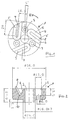
- Figures 1 and 2 show a rotor wiper body 1, which in the essentially a circular cylindrical shape with a central one Has bore 2, which serves to receive a cylinder that is described in more detail below in connection with Figure 4.
- the grooves 5 extend from a central region of the Rotor wiper body 1 near the central bore 2 and run to the edge of the rotor wiper body 1.
- the grooves 5 are in Angle to the radial 8 arranged, in such a way that the inner area of the groove 5 when the rotor wiper body rotates in Direction of arrow R leads the outer groove area.
- wiper strips 9 are used, which with a thickened head portion 10 held in the bottom groove portion 7 are.
- the rubber wiper strips 9 are on one Grooved wall 6, wherein they change when the direction of rotation of the Place the rotor wiper body 1 on the other groove wall can.
- the rotor wiper body 1 rotates the direction of rotation indicated by the arrow R in FIG.
- the water / dirt particles / air mixture formed during the cleaning process from the wiper strips 9 smooth conveyed radially outwards, where the mixture is suctioned off.
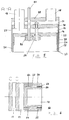
- Figures 3 to 6 show in a largely schematic manner, that the cleaning head 11 has a cleaning chamber 12 in which the arranged in total with 13 designated cleaning devices are behind it, separated by an intermediate wall 14 Suction chamber 15 and one through another partition 16 has separate air supply chamber 17 located behind it.
- the air supply chamber 17 is by one with the reference numeral 18 indicated line connected to a compressed air circuit, while the suction chamber 15 via a line 19 with connected to a pump (not shown) that the sucked-off dirty water / air mixture into a container.
- the air supply chamber 17 can also be omitted.
- the air supply chamber 17 guides the compressed air through an external one Ring channel 22 to the surface to be cleaned, where they are under the Edge 23 of a circumferential partition 24 between the air supply ring channel 22 and an annular circumferential Suction channel 25 passes through, which is connected to the suction chamber 15 stands.
- Another circumferential partition 26 borders the Suction channel 25 from the cleaning chamber 12.
- the outer boundary wall of the air supply duct 22 is denoted by the reference symbol 27 marked.
- the cleaning devices 13 contain a fixed one Bearing journal (which could also be called a piston) 21, who sits in a bore of the partition 14 and in the area of partition 16 behind it in the end portion of the Hose 20 engages.
- the bearing pin 21 contains an axial through bore 28, the front outlet opening 29 the Bottom 30 of a cylinder 31 is opposite, which is rotatable on the Bearing journal 21 sits.
- Through the bottom 30 of the cylinder 31 leads at least one through hole directed obliquely outwards 32, from which through the hose 20 preferably with 1 to 2 bar supplied cleaning liquid - water, the appropriate cleaning additives can be added after passing through the axial bore 28 emerges. Since the cylinder 31 in the operation of the Cleaning head 11 rotates, that which emerges from the opening 32 Water distributed along a circle.
- a rotor wiper body 33 is connected to the cylinder 31 in a rotational test, for example by means of screws 34, of which in Fig. 4 is shown. Wiper strips are in the rotor wiper body 33 35 let in, which is only schematic in the figure, but are not indicated to scale.
- the cleaning device 13 also includes a gear 38, the Rotate test with the rotor wiper body 33 via a driver 39 connected is.
- This driver is with a threaded section 40 screwed into a threaded bore of the gear 38 and passes through a through hole with a threadless shaft 41 42 through the rotor wiper body 33 with little lateral Game.
- the driver 39 also has a head 43 which in the starting position shown in Fig. 4, in which no water is fed through the hose 20 and the through-channel 28, from the end face 44 of the rotor wiper body 33 by a predetermined one Distance is spaced.
- the cylinder 31 is seated in the longitudinal direction of the journal 21 (Arrow X in Fig. 4) slidably on the journal 21. Since the Rotor wiper body 33 is fixedly connected to cylinder 31, is therefore the entire rotatable arrangement of cylinder 31, Rotor wiper body 33 and the associated wiper strips 35 in Slidable in the X direction until the end face 44 of the rotor wiper body 33 onto the head 43 of the driver 39 hits. It is understood that the gear 38 in the X direction is not arranged to be displaceable.
- the cylinder 31 is thereby X direction advanced, whereby the wiper strips 35, which in the starting position shown in FIG. 4 is approximately up to one Distance of 2 min from the front end plane 45 of the cleaning head 11 extend, are pressed against the surface to be cleaned.
- the contact pressure depends, among other things, on the pressure of the water supplied and the cross-sectional dimensions of the through-channel 28 and the through bore 32.
- a drive shaft leads to drive the cleaning devices 13 47 through the outer rear wall 48 and the intermediate walls 16 and 14 of the cleaning head 11 and is in the cleaning chamber 12 connected to a drive pinion 49 which is connected to the gear 38 who can comb a cleaning device 13. So the other Cleaning device rotates in the same direction of rotation, can Comb the drive pinion 49 with an intermediate gear 50 in engagement with the gear 38 of the adjacent cleaning device stands.
- the cleaning head 11 passed smoothly over window surfaces are in the four corner areas 52 of the plan rectangular cleaning head 11 point or circular hydrostatic Camp 53 trained.
- the cleaning fluid source related channels 54 are provided, in the front ends of screws 55 with through holes 56 of a suitable diameter are used.
Landscapes
- Cleaning By Liquid Or Steam (AREA)
- Surface Treatment Of Glass (AREA)
Applications Claiming Priority (2)
| Application Number | Priority Date | Filing Date | Title |
|---|---|---|---|
| DE19836653 | 1998-08-13 | ||
| DE19836653A DE19836653C2 (de) | 1998-08-13 | 1998-08-13 | Reinigungskopf |
Publications (2)
| Publication Number | Publication Date |
|---|---|
| EP0979631A2 true EP0979631A2 (fr) | 2000-02-16 |
| EP0979631A3 EP0979631A3 (fr) | 2000-07-12 |
Family
ID=7877378
Family Applications (1)
| Application Number | Title | Priority Date | Filing Date |
|---|---|---|---|
| EP99115441A Withdrawn EP0979631A3 (fr) | 1998-08-13 | 1999-08-05 | Tête de nettoyage |
Country Status (2)
| Country | Link |
|---|---|
| EP (1) | EP0979631A3 (fr) |
| DE (1) | DE19836653C2 (fr) |
Cited By (1)
| Publication number | Priority date | Publication date | Assignee | Title |
|---|---|---|---|---|
| CN112547597A (zh) * | 2021-01-05 | 2021-03-26 | 吴怡蕊 | 一种用于浇注机器人的混合头浇注嘴的清理装置 |
Family Cites Families (7)
| Publication number | Priority date | Publication date | Assignee | Title |
|---|---|---|---|---|
| US1537273A (en) * | 1920-04-06 | 1925-05-12 | Francis W Tully | Window-cleaning apparatus |
| GB1445402A (en) * | 1973-07-11 | 1976-08-11 | Wynstruments Ltd | Windscreen wiping device |
| JPS5221823B2 (fr) * | 1974-02-27 | 1977-06-13 | ||
| JPS596974A (ja) * | 1982-07-05 | 1984-01-14 | カネボウ株式会社 | 洗浄方法 |
| GB2166342B (en) * | 1984-10-06 | 1988-02-10 | Gerritt Broersz | Underwater scouring apparatus |
| US4800607A (en) * | 1987-04-21 | 1989-01-31 | Nihon Biso Kabushiki Kaisha | Apparatus for cleaning windowpanes |
| DE19715562C1 (de) * | 1997-04-15 | 1998-08-27 | Fidor Vermoegensverwaltung Gmb | Bürstenreinigungskopf |
-
1998
- 1998-08-13 DE DE19836653A patent/DE19836653C2/de not_active Expired - Fee Related
-
1999
- 1999-08-05 EP EP99115441A patent/EP0979631A3/fr not_active Withdrawn
Cited By (1)
| Publication number | Priority date | Publication date | Assignee | Title |
|---|---|---|---|---|
| CN112547597A (zh) * | 2021-01-05 | 2021-03-26 | 吴怡蕊 | 一种用于浇注机器人的混合头浇注嘴的清理装置 |
Also Published As
| Publication number | Publication date |
|---|---|
| DE19836653C2 (de) | 2002-01-03 |
| EP0979631A3 (fr) | 2000-07-12 |
| DE19836653A1 (de) | 2000-02-24 |
Similar Documents
| Publication | Publication Date | Title |
|---|---|---|
| DE69812868T2 (de) | Flanschreformierungsanlage | |
| DE1621561B2 (de) | Vorrichtung zum reinigen von speicherplatten | |
| DE102016002585B3 (de) | Vorrichtung zum Behandeln von Material | |
| DE3308586C2 (de) | Vorrichtung zur spitzenlosen, spanenden Außenfeinbearbeitung von länglichen Werkstücken | |
| DE3616742A1 (de) | Schaelmaschine, insbesondere kartoffelschaelmaschine | |
| EP1720666B1 (fr) | Tête de nettoyage de surface | |
| EP3245024B1 (fr) | Machine-outil présentant un dispositif de transport pour l'évacuation de copeaux | |
| DE19715562C1 (de) | Bürstenreinigungskopf | |
| DE102016011683A1 (de) | Vorrichtung zum Schleifen der Seitenkanten eines Wintersportgerätes | |
| CH627101A5 (fr) | ||
| DE29504112U1 (de) | Reinigungsvorrichtung für Räder | |
| DE19836653C2 (de) | Reinigungskopf | |
| DE19808804A1 (de) | Maschine zur Oberflächenbearbeitung mindestens einer textilen Warenbahn, insbesondere zum Rauhen und/oder Schmirgeln od. dgl. | |
| DE4324532A1 (de) | Sandstrahlvorrichtung zum Polieren und Reinigen von Rädern | |
| EP1056550B1 (fr) | Tete de nettoyage d'un dispositif de nettoyage pour surface de fenetres et de facades | |
| DE10055140C1 (de) | Anordnung zum Bearbeiten von langgestreckten Hohlräumen | |
| AT519785A2 (de) | Verbesserte Werkzeugmaschine | |
| AT519215B1 (de) | WERKZEUG ZUR REINIGUNG VON GROßEN FLÄCHEN | |
| LU602431B1 (de) | Eine intelligente automatisierte Vorrichtung zur Reinigung und Trocknung von Sportgeräten in einem | |
| DE10241334B4 (de) | Luftreinigungsvorrichtung für Abschwartungs-, Enthäutungs- und/oder Entvliesmaschinen | |
| DE3243062A1 (de) | Schuhputzautomat | |
| DE1621561C (de) | Vorrichtung zum Reinigen von Speicherplatten | |
| DE2732882C3 (de) | Einrichtung zur Reinigung des Innengewindes von Muttern | |
| DE102012102169A1 (de) | Vorrichtung zur Bearbeitung eines kreiszylindrischen Werkstücks | |
| CH687442A5 (de) | Einrichtung zum Reinigen von Gebinden. |
Legal Events
| Date | Code | Title | Description |
|---|---|---|---|
| PUAI | Public reference made under article 153(3) epc to a published international application that has entered the european phase |
Free format text: ORIGINAL CODE: 0009012 |
|
| AK | Designated contracting states |
Kind code of ref document: A2 Designated state(s): AT BE CH CY DE DK ES FI FR GB GR IE IT LI LU MC NL PT SE |
|
| AX | Request for extension of the european patent |
Free format text: AL;LT;LV;MK;RO;SI |
|
| PUAL | Search report despatched |
Free format text: ORIGINAL CODE: 0009013 |
|
| AK | Designated contracting states |
Kind code of ref document: A3 Designated state(s): AT BE CH CY DE DK ES FI FR GB GR IE IT LI LU MC NL PT SE |
|
| AX | Request for extension of the european patent |
Free format text: AL;LT;LV;MK;RO;SI |
|
| AKX | Designation fees paid | ||
| STAA | Information on the status of an ep patent application or granted ep patent |
Free format text: STATUS: THE APPLICATION IS DEEMED TO BE WITHDRAWN |
|
| 18D | Application deemed to be withdrawn |
Effective date: 20010113 |