EP0977964B1 - Continuous-flow steam generator and method for starting same - Google Patents
Continuous-flow steam generator and method for starting same Download PDFInfo
- Publication number
- EP0977964B1 EP0977964B1 EP98931919A EP98931919A EP0977964B1 EP 0977964 B1 EP0977964 B1 EP 0977964B1 EP 98931919 A EP98931919 A EP 98931919A EP 98931919 A EP98931919 A EP 98931919A EP 0977964 B1 EP0977964 B1 EP 0977964B1
- Authority
- EP
- European Patent Office
- Prior art keywords
- steam generator
- tubes
- heating surface
- steam
- throttle cable
- Prior art date
- Legal status (The legal status is an assumption and is not a legal conclusion. Google has not performed a legal analysis and makes no representation as to the accuracy of the status listed.)
- Expired - Lifetime
Links
Images

Classifications
-
- F—MECHANICAL ENGINEERING; LIGHTING; HEATING; WEAPONS; BLASTING
- F22—STEAM GENERATION
- F22B—METHODS OF STEAM GENERATION; STEAM BOILERS
- F22B29/00—Steam boilers of forced-flow type
- F22B29/06—Steam boilers of forced-flow type of once-through type, i.e. built-up from tubes receiving water at one end and delivering superheated steam at the other end of the tubes
- F22B29/061—Construction of tube walls
- F22B29/062—Construction of tube walls involving vertically-disposed water tubes
-
- F—MECHANICAL ENGINEERING; LIGHTING; HEATING; WEAPONS; BLASTING
- F22—STEAM GENERATION
- F22B—METHODS OF STEAM GENERATION; STEAM BOILERS
- F22B35/00—Control systems for steam boilers
- F22B35/06—Control systems for steam boilers for steam boilers of forced-flow type
- F22B35/14—Control systems for steam boilers for steam boilers of forced-flow type during the starting-up periods, i.e. during the periods between the lighting of the furnaces and the attainment of the normal operating temperature of the steam boilers
Definitions
- the invention relates to a once-through steam generator according to the preamble of claim 1.
- Such Steam generator is known from EP 0 308 728 A1.
- a continuous steam generator In a once-through steam generator, the heating of a number of evaporator tubes, which together form the gas-tight peripheral wall of a combustion chamber, leads to complete evaporation of the flow medium in the evaporator tubes in one pass. After its evaporation, the flow medium - usually water - is supplied to the superheater tubes connected downstream of the evaporator tubes and overheated there.
- a high live steam pressure promotes high thermal efficiency and thus low CO 2 emissions from a fossil-fired power plant.
- Such a continuous steam generator can be built in or be designed in a two-pass design.
- Steam generator tubes are usually in the draft type to form the perimeter wall of one Throttle cable welded together gas-tight, the throttle cable is arranged vertically.
- the the surrounding wall of the throttle cable Forming steam generator tubes usually include both Evaporator tubes as well as these on the fluid side downstream superheater tubes.
- the throttle cable is usually a combustion chamber with a number provided by burners for fossil fuel.
- a continuous steam generator in two-pass design are common also steam generator pipes to form the surrounding wall of a vertically arranged first gas train gastight welded together.
- This type is the first Throttle cable, however, on the hot gas side via a horizontal gas cable followed by a second vertically arranged throttle cable, the Surrounding wall also formed by steam generator tubes is, and that of the heating gas usually from top to bottom is flowed through.
- a continuous steam generator in two-pass design shows in comparison to a continuous steam generator in draft type usually has a lower height and differentiates differ from this in a number of design parameters.
- these are the peripheral wall of the first gas train forming steam generator tubes usually designed as evaporator tubes, whereas Steam generator tubes designed as superheater tubes the peripheral wall of the second throttle cable and / or part of one Wall heating surface of the horizontal throttle cable.
- those assigned to the horizontal throttle cable and those to the second gas cable Steam generator tubes are those assigned to the first throttle cable Steam generator tubes usually on the flow medium side downstream.
- the first throttle cable assigned steam generator tubes on the output side into one of them common outlet collector, via a water-steam separator and over a number of in the horizontal throttle arranged heating surfaces an entry collector for the steam generator pipes assigned to the second throttle cable is.
- FIG. 2 A continuous steam generator is shown in FIG. 2 in US Pat. No. 2,982,267 shown, in which a first evaporator pipe in lower part of the first throttle cable on the flow medium side Type bulkhead heating surface immediately downstream and in one Space within the first throttle cable above one Combustion chamber is arranged.
- this heating surface is a combination of evaporator heating surface and superheater heating surface and only the evaporator part is the water-steam separator downstream.
- the invention is therefore based on the object in To specify the two-pass type of continuous steam generator, which is particularly long even with frequent starting operations Has lifespan.
- a particularly inexpensive method is said to start up such a once-through steam generator can be specified.
- the invention is based on the consideration that for a particularly long lifespan of the once-through steam generator too in the case of frequent starting operations, the thermal tensions between the Boundary wall of the first throttle cable and the walls of the horizontal throttle cable should be kept particularly low. To the temperature differences between the immediately before starting the burner, fill it with cold feed water, the steam generator tubes assigned to the first throttle cable and the with a warm start still relatively hot walls of the Horizontal throttle cable must be kept particularly low.
- the outlet manifold is the one of the first gas train assigned steam generator tubes in such a dimensioned Height arranged that a direct contact of the front steam generator tubes filled with cold feed water with the walls of the horizontal throttle cable still hot during a warm start is avoided.
- Steam generator pipes already during start-up Heating surfaces provided for steam generation are particularly large dimensioned. For this is the one that forms the evaporator heating surface Steam generator pipes as additional to steam generation provided heating surface downstream of the bulkhead heating surface.
- the bulkhead heating surface is within a room area of the first throttle cable above that provided in the first gas cable Combustion chamber arranged.
- the bulkhead heating surface is therefore in one especially when starting up the continuous steam generator highly heated room area arranged and contributes in particular to a large extent for steam generation.
- too a large one when the continuous steam generator is started up Amount of steam generated, which leads to a particularly effective cooling of the steam generator tubes provided as evaporator tubes downstream steam generator tubes designed as superheater tubes contributes.
- the throttle cable advantageously an approximately horizontal Dividing line between when filled with water and provided with steam-filled steam generator pipes when starting up.
- This dividing line can be designed in this way be that the thermal stresses occurring at this point are kept particularly low. A meeting of the Start-up of differently cooled heating surfaces in the transition area from the first throttle cable to the horizontal throttle cable thus safely avoided.
- a steam-side one Outlet of the water-steam separator to an inlet header for a number of others designed as superheater tubes Steam generator pipes connected, these steam generator pipes the upper part of the perimeter wall of the first Form the throttle cable, and this inlet collector in one lower compared to the lower edge of the horizontal throttle cable Height is arranged.
- the flow medium throughput is advantageously achieved by the steam generator tubes forming the evaporator heating surface after its lowering proportional to the heat output of the Continuous steam generator set.
- the advantages achieved with the invention are in particular in that by at a height between the first Accelerator cable assigned burners and the lower edge of the horizontal throttle cable arranged outlet collector of the evaporator heating surface an almost horizontal dividing line between the Start-up with water-filled steam generator tubes and with Steam-filled steam generator tubes in one to avoid them created particularly favorable area of thermal stresses is.
- the occurrence of thermal stress in the transition area from the first accelerator cable to the horizontal accelerator cable safely avoided, so that the once-through steam generator is a special long service life even with frequent starts having.
- the bulkhead heating surface also ensures that when starting, a sufficiently large evaporator heating surface is available to a particularly high Generate steam mass flow and thus safe cooling to ensure all steam generator tubes.
- the continuous steam generator according to Figure 1 comprises a number of burners 2 for a fossil fuel, which are shown in FIG are shown schematically based on their main axes.
- the Burners 2 are arranged in a combustion chamber 4, through a lower part of the peripheral wall 6 of a vertically arranged first throttle cable 8 is formed.
- the surrounding wall 6 goes at the lower end of the first throttle cable 8 formed by it into a funnel-shaped bottom 10.
- the continuous steam generator 1 according to FIG. 1 is of the two-pass type executed.
- the first throttle cable 8 is for combustion of the fossil fuel fuel gas a horizontal throttle cable 12 is followed by a second throttle cable 14.
- the second throttle cable 14 is also arranged vertically.
- the peripheral wall 6 of the first throttle cable 8 is made of steam generator tubes 16.17 built that gas-tight on its long sides connected to each other, for example welded.
- the surrounding wall 18 of the second throttle cable is of an analog design 14 also from steam generator tubes, not shown built up on their long sides gastight with each other are connected.
- the horizontal throttle cable 12 in turn comprises a number of steam generator tubes, not shown, to the surrounding wall, which is also gastight arranged heating surfaces 20 are combined.
- are the surrounding wall 6 of the first gas train 8 forming steam generator tubes 16, 17 vertically arranged.
- the steam generator tubes 16, 17 but also rising obliquely in the manner of a screw winding be arranged around the first throttle cable.
- the surrounding wall 6 of the first in a lower area Accelerator cable 8 forming steam generator tubes 16 are used as evaporator tubes designed and to a number of evaporator heating surfaces 22 summarized, each part of the perimeter wall 6 of the first throttle cable 8.
- the steam generator pipes 16 of each evaporator heating surface 22 are for the flow of Water connected as a flow medium in parallel and are with their entry ends to a common, not shown Entry collectors and with their exit ends to a common one Outlet collector 24 connected.
- the outlet header 24 is one on the flow medium side Bulkhead heating surface 26 connected.
- the bulkhead heating surface 26 is from a number of, not shown, for the flow of the flow medium connected in parallel Steam generator tubes built, the input side to one common entrance collector 28 and on the exit side to one common outlet collector 30 are connected.
- the the Bulb heating surface 26 forming steam generator tubes are tight arranged side by side in a plane and form a number of plate-like heating surfaces within the first throttle cable 8 or the horizontal throttle cable 12 suspended are.
- the bulkhead heating surface 26 is a water-steam separation device on the flow medium side 34 downstream, the steam side Outlet 36 to an inlet header 38 for a number further, only indicated in Figure 1 for a better overview Steam generator tubes 17 is connected.
- the others Steam generator tubes 17 are designed as superheater tubes and to a number of superheater heating surfaces, not shown summarized the 32 in the upper room Form the peripheral wall 6 of the first throttle cable 8.
- In the flow path between the outlet header 24 and the water-steam separator 34 is bypassing the bulkhead heating surface 26 also one that can be shut off with a bypass valve 40 Bypass line 42 switched.
- the steam generator tubes 16,17 in an area at the level of the outlet collector 24 and the Entry collector 38 in a toothed arrangement in the surrounding wall 6 of the first throttle cable 8 is mounted.
- the surrounding wall 6 of the first throttle cable 8 forming steam generator tubes 16 in two groups of Steam generator tubes 16a and 16b combined the a larger group assigned to the first group Have length than that assigned to the second group Steam generator tubes 16b.
- Each of the comparatively shorter steam generator tubes 17b is above a comparatively longer one Steam generator tube 16a arranged, each of the comparatively longer steam generator tubes 17a above each a comparatively shorter steam generator tube 16b is.
- both open out comparatively shorter steam generator tubes 16b as well comparatively longer steam generator tubes 16a in the outlet header 24, being for the comparatively longer Steam generator pipes 16a each have a feed pipe section 16c is provided.
- Both the comparatively shorter ones are analogous Steam generator tubes 17a as well as the comparatively longer ones Steam generator tubes 17b connected to the inlet header 38.
- the other steam generator tubes 17 on the flow medium side in the horizontal gas flue 12 arranged heating surfaces 20 the surrounding wall 18 of the second throttle cable 14 forming steam generator tubes downstream.
- Both the heating surfaces 20 of the horizontal throttle cable 12 forming steam generator tubes as well as the surrounding wall 18 of the second throttle cable 14 forming steam generator tubes are intended as superheater tubes and with regard to their interpretation depending on the location of their arrangement Adjusted heating gas and flow medium parameters.
- the one as superheater tubes trained further steam generator tubes 17 upstream together Entry collector 38 is at a height between the outlet header 24 and the lower edge 44 of the Horizontal throttle cable arranged, that is in a compared to Outlet collector 24 larger and compared to the lower edge 44 of the horizontal throttle cable 12 lower height.
- the bulkhead heating surface 26 also ensures that when starting up a sufficiently large evaporator heating surface Is available to ensure safe cooling of the steam generator tubes 16 downstream of the flow medium, steam generator tubes designed as superheater tubes 17 to ensure.
- evaporator heating surface Is available to ensure safe cooling of the steam generator tubes 16 downstream of the flow medium, steam generator tubes designed as superheater tubes 17 to ensure.
- Through the bulkhead heating surface 26 is above also a buffer for when starting off the evaporated heating surface 22 expelled undevaporated flow medium created. That got into the bulkhead heating surface 26 undevaporated flow medium evaporates there, so that the water output of the once-through steam generator 1 when starting up and the associated heat loss is particularly low.
Description
Die Erfindung bezieht sich auf einen Durchlaufdampferzeuger gemäß dem Oberbegriff des Anspruchs 1. Ein derartiger Dampferzeuger ist aus der EP 0 308 728 A1 bekannt.The invention relates to a once-through steam generator according to the preamble of claim 1. Such Steam generator is known from EP 0 308 728 A1.
In einem Durchlaufdampferzeuger führt die Beheizung einer Anzahl von Verdampferrohren, die zusammen die gasdichte Umfassungswand einer Brennkammer bilden, zu einer vollständigen Verdampfung des strömungsmediums in den Verdampferrohren in einem Durchgang. Das Strömungsmedium - üblicherweise Wasser - wird nach seiner Verdampfung den Verdampferrohren nachgeschalteten Überhitzerrohren zugeführt und dort überhitzt. Ein Durchlaufdampferzeuger unterliegt im Gegensatz zu einem Naturumlaufdampferzeuger keiner Druckbegrenzung, so daß Frischdampfdrücke weit über dem kritischen Druck von Wasser (Pkrit = 221 bar) - wo es nur noch einen geringen Dichteunterschied gibt zwischen flüssigkeitsähnlichem und dampfähnlichem Medium - möglich sind. Ein hoher Frischdampfdruck begünstigt einen hohen thermischen Wirkungsgrad und somit niedrige CO2-Emissionen eines fossil beheizten Kraftwerks.In a once-through steam generator, the heating of a number of evaporator tubes, which together form the gas-tight peripheral wall of a combustion chamber, leads to complete evaporation of the flow medium in the evaporator tubes in one pass. After its evaporation, the flow medium - usually water - is supplied to the superheater tubes connected downstream of the evaporator tubes and overheated there. In contrast to a natural circulation steam generator, a continuous steam generator is not subject to any pressure limitation, so that live steam pressures far above the critical pressure of water (P crit = 221 bar) - where there is only a slight difference in density between liquid-like and steam-like medium - are possible. A high live steam pressure promotes high thermal efficiency and thus low CO 2 emissions from a fossil-fired power plant.
Ein derartiger Durchlaufdampferzeuger kann in Einzugbauart oder auch in Zweizugbauart ausgeführt sein. Bei einem Durchlaufdampferzeuger in Einzugbauart sind üblicherweise Dampferzeugerrohre zur Bildung der Umfassungswand eines einzigen Gaszuges gasdicht miteinander verschweißt, wobei der Gaszug vertikal angeordnet ist. Die die Umfassungswand des Gaszuges bildenden Dampferzeugerrohre umfassen dabei in der Regel sowohl Verdampferrohre als auch diesen strömungsmittelseitig nachgeschaltete Überhitzerrohre. In einem unteren Raumbereich des Gaszuges ist üblicherweise eine Brennkammer mit einer Anzahl von Brennern für fossilen Brennstoff vorgesehen. Such a continuous steam generator can be built in or be designed in a two-pass design. With a once-through steam generator Steam generator tubes are usually in the draft type to form the perimeter wall of one Throttle cable welded together gas-tight, the throttle cable is arranged vertically. The the surrounding wall of the throttle cable Forming steam generator tubes usually include both Evaporator tubes as well as these on the fluid side downstream superheater tubes. In a lower area the throttle cable is usually a combustion chamber with a number provided by burners for fossil fuel.
Bei einem Durchlaufdampferzeuger in Zweizugbauart sind üblicherweise ebenfalls Dampferzeugerrohre zur Bildung der Umfassungswand eines vertikal angeordneten ersten Gaszuges gasdicht miteinander verschweißt. Bei dieser Bauart ist dem ersten Gaszug jedoch heizgasseitig über einen Horizontalgaszug ein zweiter vertikal angeordneter Gaszug nachgeschaltet, dessen Umfassungswand ebenfalls von Dampferzeugerrohren gebildet ist, und der vom Heizgas üblicherweise von oben nach unten durchströmt wird. Ein Durchlaufdampferzeuger in Zweizugbauart weist im Vergleich zu einem Durchlaufdampferzeuger in Einzugbauart üblicherweise eine niedrigere Bauhöhe auf und unterscheidet sich von diesem in einer Anzahl von Auslegungsparametern.In a continuous steam generator in two-pass design are common also steam generator pipes to form the surrounding wall of a vertically arranged first gas train gastight welded together. This type is the first Throttle cable, however, on the hot gas side via a horizontal gas cable followed by a second vertically arranged throttle cable, the Surrounding wall also formed by steam generator tubes is, and that of the heating gas usually from top to bottom is flowed through. A continuous steam generator in two-pass design shows in comparison to a continuous steam generator in draft type usually has a lower height and differentiates differ from this in a number of design parameters.
Bei einem Durchlaufdampferzeuger in Zweizugbauart sind die die Umfassungswand des ersten Gaszuges bildenden Dampferzeugerrohre üblicherweise als Verdampferrohre ausgelegt, wohingegen als Überhitzerrohre ausgelegte Dampferzeugerrohre Teil der Umfassungswand des zweiten Gaszuges und/oder Teil einer Wandheizfläche des Horizontalgaszuges sind. Mit anderen Worten: die dem Horizontalgaszug und die dem zweiten Gaszug zugeordneten Dampferzeugerrohre sind den dem ersten Gaszug zugeordneten Dampferzeugerrohren strömungsmediumsseitig üblicherweise nachgeschaltet. Dazu münden die dem ersten Gaszug zugeordneten Dampferzeugerrohre ausgangsseitig in einen ihnen gemeinsamen Austrittssammler, dem über eine Wasser-Dampf-Trenneinrichtung und über eine Anzahl von im Horizontalgaszug angeordneten Heizflächen ein Eintrittssammler für die dem zweiten Gaszug zugeordneten Dampferzeugerrohre nachgeschaltet ist.For a continuous steam generator in two-pass design, these are the peripheral wall of the first gas train forming steam generator tubes usually designed as evaporator tubes, whereas Steam generator tubes designed as superheater tubes the peripheral wall of the second throttle cable and / or part of one Wall heating surface of the horizontal throttle cable. In other words: those assigned to the horizontal throttle cable and those to the second gas cable Steam generator tubes are those assigned to the first throttle cable Steam generator tubes usually on the flow medium side downstream. To this end, the first throttle cable assigned steam generator tubes on the output side into one of them common outlet collector, via a water-steam separator and over a number of in the horizontal throttle arranged heating surfaces an entry collector for the steam generator pipes assigned to the second throttle cable is.
Bei dem aus der EP 0 308 728 A1 bekannten Durchlaufdampferzeuger sind eine Anzahl von für die Durchströmung eines Strömungsmediums parallel geschalteten Dampferzeugerrohren miteinander zu einer Verdampferheizfläche verbunden, die Teil einer Umfassungswand des ersten Gaszuges ist. Dabei münden die die Verdampferheizfläche bildenden Dampferzeugerrohre ausgangsseitig in einen ihnen gemeinsamen, in einer im Vergleich zu einer Unterkante des Horizontalgaszuges niedrigeren Höhe angeordneten Austrittssammler.In the continuous steam generator known from EP 0 308 728 A1 are a number of for the flow of a flow medium steam generator tubes connected in parallel with each other connected to an evaporator heating surface, the part is a peripheral wall of the first throttle cable. This leads to the steam generator tubes forming the evaporator heating surface on the output side in a common one, in a comparison lower to a lower edge of the horizontal throttle cable Outlet collector at a height.
Bei einer derartigen Anordnung können, insbesondere beim auch als Warmstart bezeichneten Anfahren nach einer vergleichsweise kurzen Stillstandszeit vor dem Zünden der Brenner, beim Füllen von Dampferzeugerrohren des noch warmen Durchlaufdampferzeugers mit kaltem Speisewasser erhebliche Temperaturdifferenzen zwischen den dem ersten Gaszug zugeordneten Dampferzeugerrohren und einer Umfassungswand des Horizontalzuges zugeordneten Dampferzeugerrohren auftreten. Derartige Temperaturdifferenzen können insbesondere an einer Verbindungsstelle, an der eine Umfassungswand des ersten Gaszuges mit einer Wand des Horizontalzuges verschweißt ist, unzulässige Wärmespannungen hervorrufen. Aufgrund derartiger Wärmespannungen ist, insbesondere bei häufigen Anfahrvorgängen, die Lebensdauer eines derartigen Durchlaufdampferzeugers infolge hoher Wechselbeanspruchung nur begrenzt. Die Wärmespannungen treten dabei in besonderem Maße nach einem nur kurzen Stillstand des Durchlaufdampferzeugers, also beispielsweise nach einem Nachtstillstand, auf, da dann der Durchlaufdampferzeuger üblicherweise noch eine im Vergleich zur Temperatur des Speisewassers erhöhte Temperatur aufweist.With such an arrangement, in particular also with a warm start called after a comparatively short downtime before igniting the burner when Filling of steam generator tubes of the still warm continuous steam generator with cold feed water considerable temperature differences between those assigned to the first throttle cable Steam generator tubes and a peripheral wall of the horizontal train assigned steam generator pipes occur. such Temperature differences can in particular at a connection point, on the one peripheral wall of the first throttle cable is welded to a wall of the horizontal train, impermissible Cause heat stress. Because of such thermal stresses is, especially with frequent starts, the life of such a continuous steam generator as a result high alternating loads only limited. The thermal stresses occur particularly after a short The continuous steam generator comes to a standstill, for example after a night standstill, because then the continuous steam generator usually one compared to temperature of the feed water has an elevated temperature.
In der US 2,982,267 ist in der Figur 2 ein Durchlaufdampferzeuger gezeigt, bei dem einer ersten Verdampferberohrung im unteren Teil des ersten Gaszugs strömungsmediumsseitig eine Art Schottheizfläche unmittelbar nachgeschaltet und in einem Raumbereich innerhalb des ersten Gaszugs oberhalb einer Brennkammer angeordnet ist. Allerdings ist diese Heizfläche eine Kombination von Verdampferheizfläche und Überhitzerheizfläche und nur dem Verdampferteil ist die Wasser-Dampf-Trennvorrichtung nachgeschaltet.A continuous steam generator is shown in FIG. 2 in US Pat. No. 2,982,267 shown, in which a first evaporator pipe in lower part of the first throttle cable on the flow medium side Type bulkhead heating surface immediately downstream and in one Space within the first throttle cable above one Combustion chamber is arranged. However, this heating surface is a combination of evaporator heating surface and superheater heating surface and only the evaporator part is the water-steam separator downstream.
Der Erfindung liegt daher die Aufgabe zugrunde, einen in Zweizugbauart ausgeführten Durchlaufdampferzeuger anzugeben, der auch bei häufigen Anfahrvorgängen eine besonders lange Lebensdauer aufweist. Zudem soll ein besonders günstiges Verfahren zum Anfahren eines derartigen Durchlaufdampferzeugers angegeben werden.The invention is therefore based on the object in To specify the two-pass type of continuous steam generator, which is particularly long even with frequent starting operations Has lifespan. In addition, a particularly inexpensive method is said to start up such a once-through steam generator can be specified.
Bezüglich eines Durchlaufdampferzeugers der obengenannten Art wird diese Aufgabe erfindungsgemäß dadurch gelöst, daß dem Austrittssammler strömungsmediumsseitig eine Schottheizfläche unmittelbar nachgeschaltet ist, wobei die Schottheizfläche in einem Raumbereich innerhalb des ersten Gaszuges oberhalb einer Brennkammer angeordnet ist und wobei der Schottheizfläche strömungsmediumsseitig eine Wasser-Dampf-Trennvorrichtung nachgeschaltet ist.Regarding a once-through steam generator of the type mentioned above This object is achieved in that the Outlet collector, a bulkhead heating surface on the flow medium side is immediately connected, the bulkhead heating surface in a space within the first throttle cable above one Combustion chamber is arranged and the bulkhead heating surface a water-steam separation device on the flow medium side is connected downstream.
Unter Schottheizfläche ist dabei eine Anzahl von für den Durchfluß des Strömungsmediums parallel geschalteten, in einen gemeinsamen Eintritts- und in einen gemeinsamen Austrittssammler mündenden Dampferzeugerrohren zu verstehen, wobei die Dampferzeugerrohre dicht nebeneinander in einer Ebene liegen und somit eine Anzahl von plattenartigen Heizflächen bilden, die innerhalb des Gaszuges aufgehängt sind.Under the bulkhead heating surface there is a number of for the Flow of the flow medium connected in parallel, in one common entry and exit collector to understand opening steam generator tubes, wherein the steam generator tubes close together in one plane lie and thus a number of plate-like heating surfaces form, which are suspended within the throttle cable.
Die Erfindung geht dabei von der Überlegung aus, daß für eine besonders lange Lebensdauer des Durchlaufdampferzeugers auch bei häufigen Anfahrvorgängen die Wärmespannungen zwischen der Umfassungswand des ersten Gaszuges und den Wänden des Horizontalgaszuges besonders gering gehalten sein sollten. Dazu sollten die Temperaturdifferenzen zwischen den unmittelbar vor dem Zünden der Brenner mit kaltem Speisewasser gefüllten, dem ersten Gaszug zugeordneten Dampferzeugerrohren und den bei einem Warmstart noch vergleichsweise heißen Wänden des Horizontalgaszuges besonders gering gehalten sein.The invention is based on the consideration that for a particularly long lifespan of the once-through steam generator too in the case of frequent starting operations, the thermal tensions between the Boundary wall of the first throttle cable and the walls of the horizontal throttle cable should be kept particularly low. To the temperature differences between the immediately before starting the burner, fill it with cold feed water, the steam generator tubes assigned to the first throttle cable and the with a warm start still relatively hot walls of the Horizontal throttle cable must be kept particularly low.
Dazu ist einerseits der Austrittssammler der dem ersten Gaszug zugeordneten Dampferzeugerrohre in einer derart bemessenen Höhe angeordnet, daß ein unmittelbarer Kontakt der vor dem Anfahren mit kaltem Speisewasser gefüllten Dampferzeugerrohre mit den bei einem Warmstart noch heißen Wänden des Horizontalgaszuges vermieden ist. Andererseits sind für eine besonders effektive Kühlung der dem Horizontalgaszug zugeordneten Dampferzeugerrohren bereits während des Anfahrens die zur Dampferzeugung vorgesehenen Heizflächen besonders groß dimensioniert. Dazu ist den die Verdampferheizfläche bildenden Dampferzeugerrohren als zusätzliche zur Dampferzeugung vorgesehene Heizfläche die Schottheizfläche nachgeschaltet. For this purpose, on the one hand, the outlet manifold is the one of the first gas train assigned steam generator tubes in such a dimensioned Height arranged that a direct contact of the front steam generator tubes filled with cold feed water with the walls of the horizontal throttle cable still hot during a warm start is avoided. On the other hand, for one particularly effective cooling of the horizontal throttle cable Steam generator pipes already during start-up Heating surfaces provided for steam generation are particularly large dimensioned. For this is the one that forms the evaporator heating surface Steam generator pipes as additional to steam generation provided heating surface downstream of the bulkhead heating surface.
Dabei ist die Schottheizfläche in einem Raumbereich innerhalb des ersten Gaszuges oberhalb der im ersten Gaszug vorgesehenen Brennkammer angeordnet. Die Schottheizfläche ist somit in einem auch beim Anfahren des Durchlaufdampferzeugers besonders stark beheizten Raumbereich angeordnet und trägt in besonders hohem Maße zur Dampferzeugung bei. Somit wird auch beim Anfahren des Durchlaufdampferzeugers bereits eine große Dampfmenge erzeugt, die zu einer besonders effektiven Kühlung der den als Verdampferrohren vorgesehenen Dampferzeugerrohren nachgeschalteten, als Überhitzerrohre ausgelegten Dampferzeugerrohren beiträgt.The bulkhead heating surface is within a room area of the first throttle cable above that provided in the first gas cable Combustion chamber arranged. The bulkhead heating surface is therefore in one especially when starting up the continuous steam generator highly heated room area arranged and contributes in particular to a large extent for steam generation. Thus, too a large one when the continuous steam generator is started up Amount of steam generated, which leads to a particularly effective cooling of the steam generator tubes provided as evaporator tubes downstream steam generator tubes designed as superheater tubes contributes.
Für besonders geringe Wärmespannungen zwischen den Wandheizflächen des ersten Gaszuges und den Wandheizflächen des Horizcntalgaszuges ist in einem Raumbereich oberhalb der im ersten Gaszug angeordneten Brenner und unterhalb der Unterkante des Gaszuges vorteilhafterweise eine annähernd waagerechte Trennlinie zwischen beim Anfahren mit Wasser gefüllten und beim Anfahren mit Dampf gefüllten Dampferzeugerrohren vorgesehen. Diese Trennlinie kann konstruktiv derart ausgebildet sein, daß die an dieser Stelle auftretenden Wärmespannungen besonders gering gehalten sind. Ein Zusammentreffen von beim Anfahren stark unterschiedlich gekühlten Heizflächen im Übergangsbereich vom ersten Gaszug auf den Horizontalgaszug ist somit sicher vermieden.For particularly low thermal stresses between the wall heating surfaces of the first gas train and the wall heating surfaces of the horizontal gas train is in a room area above that in the first Throttle cable arranged burner and below the lower edge the throttle cable advantageously an approximately horizontal Dividing line between when filled with water and provided with steam-filled steam generator pipes when starting up. This dividing line can be designed in this way be that the thermal stresses occurring at this point are kept particularly low. A meeting of the Start-up of differently cooled heating surfaces in the transition area from the first throttle cable to the horizontal throttle cable thus safely avoided.
Dazu ist eine während des Betriebs die von verdampfendem Strömungsmedium durchströmten Verdampferrohre von den von verdampftem Strömungsmedium durchströmten Überhitzerrohren entkoppelnde Wasser-Dampf-Trennvorrichtung strömungsmittelseitig der Schottheizfläche nachgeschaltet.For this purpose, one that evaporates during operation Flow medium through which the evaporator tubes flow evaporated flow medium through superheater tubes decoupling water-steam separator on the fluid side downstream of the bulkhead heating surface.
Vorteilhafte Ausgestaltungen der Erfindung sind Gegenstand der Unteransprüche.Advantageous embodiments of the invention are the subject of subclaims.
In weiterer vorteilhafter Ausgestaltung ist ein dampfseitiger Auslaß der Wasser-Dampf-Trennvorrichtung an einen Eintrittssammler für eine Anzahl weiterer, als Überhitzerrohre vorgesehener Dampferzeugerrohre angeschlossen, wobei diese Dampferzeugerrohre den oberen Teil der Umfassungswand des ersten Gaszuges bilden, und wobei dieser Eintrittssammler in einer im Vergleich zur Unterkante des Horizontalgaszuges geringeren Höhe angeordnet ist. In a further advantageous embodiment, a steam-side one Outlet of the water-steam separator to an inlet header for a number of others designed as superheater tubes Steam generator pipes connected, these steam generator pipes the upper part of the perimeter wall of the first Form the throttle cable, and this inlet collector in one lower compared to the lower edge of the horizontal throttle cable Height is arranged.
Bezüglich des Verfahren zum Anfahren eines derartigen Durchlaufdampferzeugers in Zweizugbauart wird die genannte Aufgabe gelöst, indem nach dem Einsetzen eines Wasserausstoßes aus den die Verdampferheizfläche bildenden Dampferzeugerrohren deren Strömungsmediumsdurchsatz vorübergehend abgesenkt wird.Regarding the method for starting such a once-through steam generator in two-pass design, the task mentioned solved by after the onset of water the steam generator tubes forming the evaporator heating surface whose flow medium flow rate is temporarily reduced becomes.
Beim Anfahren eines Durchlaufdampferzeugers wird nämlich ein Teil des in den Verdampferrohren enthaltenen unverdampften Strömungsmediums oder Wassers durch Dampf ersetzt. Dieser Vorgang erfolgt während des Anfahrens und führt zu einem kurzzeitig erhöhten Strömungsmediumsdurchsatz am Austritt der Verdampferrohre, auch als Wasserausstoß bezeichnet. Der Wasserausstoß muß aus dem Durchlaufdampferzeuger üblicherweise abgeführt werden und verursacht daher einen Wärmeverlust für den Durchlaufdampferzeuger.When a continuous steam generator is started up, a Part of the non-evaporated contained in the evaporator tubes Fluid or water replaced by steam. This Process takes place during start-up and leads to a briefly increased flow medium throughput at the outlet of the Evaporator tubes, also known as water emissions. The water output must usually from the continuous steam generator are dissipated and therefore cause heat loss for the continuous steam generator.
Bei einem besonders günstigen Verfahren zum Anfahren eines Durchlaufdampferzeugers sollte daher der Wasserausstoß besonders gering gehalten sein. Dies ist für den oben dargestellten Durchlaufdampferzeuger erreichbar, indem vor dem Zünden der Brenner die der Umfassungswand des ersten Gaszuges zugeordneten Dampferzeugerrohre zunächst bis zu einer Höhe des ihnen nachgeschalteten Austrittssammlers mit unverdampftem Strömungsmedium gefüllt werden. Überschüssiges unverdampftes Strömungsmedium oder Wasser kann dabei unter Umgehung der Schottheizfläche über ein Bypassventil direkt zur Wasser-Dampf-Trennvorrichtung geleitet werden. Mit dem Zünden der Brenner wird den als Verdampferrohre ausgebildeten Dampferzeugerrohren zunächst ein Anfangsmassenstrom an Strömungsmedium oder Speisewasser zugeführt. Das Strömungsmedium verdampft in den in den Austrittssammler mündenden Dampferzeugerrohren teilweise, wobei das nicht verdampfte Strömungsmedium in die dem Austrittssammler nachgeschaltete Schottheizfläche gelangt. Da diese ebenfalls als Verdampferheizfläche ausgelegt und somit mit unverdampftem Strömungsmedium bespeisbar ist, kann das dorthin gelangte unverdampfte Strömungsmedium dort ohne schädliche Auswirkungen weiter verdampft werden. Eine ausreichende Kühlung aller Dampferzeugerrohre ist dabei sicher gewährleistet, wobei der Speisewasser-Massenstrom für einen besonders geringen Wasserausstoß nach einsetzen des Wasserausstoßes zunächst vorübergehend reduziert wird.In a particularly favorable method for starting a Pass-through steam generator should therefore especially the water output be kept low. This is for the one shown above Continuous steam generator can be reached by before igniting the burner is assigned to the peripheral wall of the first throttle cable Steam generator pipes first up to a height of downstream outlet collector with unevaporated Flow medium to be filled. Excess unevaporated Fluid or water can be bypassed Bulkhead heating surface via a bypass valve directly to the water-steam separator be directed. With the ignition of the The burner becomes the steam generator tubes designed as evaporator tubes initially an initial mass flow of flow medium or feed water supplied. The flow medium evaporates in the steam generator tubes opening into the outlet header partially, the non-evaporated flow medium into the bulkhead heating surface downstream of the outlet header arrives. Since this is also used as an evaporator heating surface designed and can thus be fed with unevaporated flow medium the undevaporated flow medium can get there evaporated there without harmful effects become. Adequate cooling of all steam generator tubes is guaranteed, the feed water mass flow for a particularly low water output use of water output temporarily reduced becomes.
Vorteilhafterweise wird der Strömungsmediumsdurchsatz durch die die Verdampferheizfläche bildenden Dampferzeugerrohre nach seiner Absenkung proportional zur Feuerwärmeleistung des Durchlaufdampferzeugers eingestellt.The flow medium throughput is advantageously achieved by the steam generator tubes forming the evaporator heating surface after its lowering proportional to the heat output of the Continuous steam generator set.
Die mit der Erfindung erzielten Vorteile bestehen insbesondere darin, daß durch den in einer Höhe zwischen den dem ersten Gaszug zugeordneten Brennern und der Unterkante des Horizontalgaszuges angeordneten Austrittssammler der Verdampferheizfläche eine annähernd waagerechte Trennlinie zwischen beim Anfahren mit Wasser gefüllten Dampferzeugerrohren und mit Dampf gefüllten Dampferzeugerrohren in einem zur Vermeidung von Wärmespannungen besonders günstigen Raumbereich geschaffen ist. Das Auftreten von Wärmespannungen im Übergangsbereich vom ersten Gaszug auf den Horizontalgaszug ist dabei sicher vermieden, so daß der Durchlaufdampferzeuger eine besonders lange Lebensdauer auch bei häufigen Anfahrvorgängen aufweist. Durch die Schottheizfläche ist zudem sichergestellt, daß beim Anfahren eine ausreichend große Verdampferheizfläche zur Verfügung steht, um einen besonders hohen Dampfmassenstrom zu erzeugen und somit eine sichere Kühlung aller Dampferzeugerrohre zu gewährleisten. Durch die Schottheizfläche ist darüber hinaus auch ein Zwischenspeicher für beim Anfahren aus der Verdampferheizfläche ausgestoßenes unverdampftes Strömungsmedium geschaffen. Das in die Schottheizfläche gelangte unverdampfte Strömungsmedium verdampft dort, so daß die aus dem Durchlaufdampferzeuger beim Anfahren abzuführende Wassermenge infolge des Wasserausstoßes besonders gering ist. The advantages achieved with the invention are in particular in that by at a height between the first Accelerator cable assigned burners and the lower edge of the horizontal throttle cable arranged outlet collector of the evaporator heating surface an almost horizontal dividing line between the Start-up with water-filled steam generator tubes and with Steam-filled steam generator tubes in one to avoid them created particularly favorable area of thermal stresses is. The occurrence of thermal stress in the transition area from the first accelerator cable to the horizontal accelerator cable safely avoided, so that the once-through steam generator is a special long service life even with frequent starts having. The bulkhead heating surface also ensures that when starting, a sufficiently large evaporator heating surface is available to a particularly high Generate steam mass flow and thus safe cooling to ensure all steam generator tubes. Through the bulkhead heating surface is also a temporary storage for Unevaporated ejected from the evaporator heating surface when starting up Flow medium created. That in the bulkhead heating surface came unevaporated flow medium evaporated there so that the from the continuous steam generator when starting up amount of water to be discharged due to the water output especially is low.
Ein Ausführungsbeispiel der Erfindung wird anhand einer Zeichnung näher erläutert. Darin zeigten:
- FIG 1
- schematisch einen Durchlaufdampferzeuger in Zweizugbauart,
- FIG 2
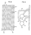
- einen Ausschnitt aus einer Umfassungswand des Durchlaufdampferzeugers nach Figur 1, und
- FIG 3
- einen Eintrittssammler und einen Austrittssammler des Durchlaufdampferzeugers nach Figur 1.
- FIG. 1
- schematically a continuous steam generator in two-pass design,
- FIG 2
- a section of a peripheral wall of the once-through steam generator according to Figure 1, and
- FIG 3
- an inlet header and an outlet header of the continuous steam generator according to Figure 1.
Gleiche Teile sind in allen Figuren mit denselben Bezugszeichen versehen.The same parts have the same reference symbols in all the figures Mistake.
Der Durchlaufdampferzeuger gemäß Figur 1 umfaßt eine Anzahl
von Brennern 2 für einen fossilen Brennstoff, die in Figur 1
anhand ihrer Hauptachsen schematisch dargestellt sind. Die
Brenner 2 sind in einer Brennkammer 4 angeordnet, die durch
einen unteren Teil der Umfassungswand 6 eines vertikal angeordneten
ersten Gaszugs 8 gebildet ist. Die Umfassungswand 6
geht am Unterende des durch sie gebildeten ersten Gaszugs 8
in einen trichterförmigen Boden 10 über.The continuous steam generator according to Figure 1 comprises a number
of
Der Durchlaufdampferzeuger 1 gemäß Figur 1 ist in Zweizugbauart
ausgeführt. Dazu ist dem ersten Gaszug 8 für aus der Verbrennung
des fossilen Brennstoffs entstehendes Heizgas über
einen Horizontalgaszug 12 ein zweiter Gaszug 14 nachgeschaltet.
Der zweite Gaszug 14 ist dabei ebenfalls vertikal angeordnet.The continuous steam generator 1 according to FIG. 1 is of the two-pass type
executed. For this purpose, the
Die Umfassungswand 6 des ersten Gaszugs 8 ist aus Dampferzeugerrohren
16,17 aufgebaut, die an ihren Längsseiten gasdicht
miteinander verbunden, beispielsweise verschweißt, sind. In
analoger Bauweise ist die Umfassungswand 18 des zweiten Gaszugs
14 ebenfalls aus nicht näher dargestellten Dampferzeugerrohren
aufgebaut, die an ihren Längsseiten gasdicht miteinander
verbunden sind. Der Horizontalgaszug 12 wiederum umfaßt
eine Anzahl von nicht näher dargestellten Dampferzeugerrohren,
die zu in seiner ebenfalls gasdicht ausgebildeten Umfassungswand
angeordneten Heizflächen 20 zusammengefaßt sind.
Wie in Figur 1 dargestellt, sind die die Umfassungswand 6 des
ersten Gaszugs 8 bildenden Dampferzeugerrohre 16,17 vertikal
angeordnet. Alternativ können die Dampferzeugerrohre 16,17
aber auch in der Art einer Schraubenwicklung schräg steigend
um den ersten Gaszug herum angeordnet sein.The
Die in einem unteren Raumbereich die Umfassungswand 6 des ersten
Gaszugs 8 bildenden Dampferzeugerrohre 16 sind als Verdampferrohre
ausgelegt und zu einer Anzahl von Verdampferheizflächen
22 zusammengefaßt, von denen jede Teil der Umfassungswand
6 des ersten Gaszugs 8 ist. Die Dampferzeugerrohre
16 jeder Verdampferheizfläche 22 sind für den Durchfluß von
Wasser als Strömungsmedium parallel geschaltet und sind mit
ihren Eintrittsenden an einen nicht dargestellten gemeinsamen
Eintrittssammler und mit ihren Austrittsenden an einen gemeinsamen
Austrittssammler 24 angeschlossen.The surrounding
Dem Austrittssammler 24 ist strömungsmediumsseitig eine
Schottheizfläche 26 nachgeschaltet. Die Schottheizfläche 26
ist dabei aus einer Anzahl von nicht näher dargestellten, für
den Durchfluß des Strömungsmediums parallel geschalteten
Dampferzeugerrohren aufgebaut, die eingangsseitig an einen
gemeinsamen Eintrittssammler 28 und ausgangsseitig an einen
gemeinsamen Austrittssammler 30 angeschlossen sind. Die die
Schottheizfläche 26 bildenden Dampferzeugerrohre sind dicht
nebeneinander in einer Ebene liegend angeordnet und bilden
eine Anzahl von plattenartigen Heizflächen, die innerhalb des
ersten Gaszuges 8 oder des Horizontalgaszuges 12 aufgehängt
sind.The
Der Schottheizfläche 26 ist strömungsmediumsseitig eine Wasser-Dampf-Trennvorrichtung
34 nachgeschaltet, deren dampfseitiger
Auslaß 36 an einen Eintrittssammler 38 für eine Anzahl
weiterer, in Figur 1 zur besseren Übersicht lediglich angedeuteter
Dampferzeugerrohre 17 angeschlossen ist. Die weiteren
Dampferzeugerrohre 17 sind als Überhitzerrohre ausgelegt
und zu einer Anzahl von nicht näher dargestellten Überhitzerheizflächen
zusammengefaßt, die im oberen Raumbereich 32 die
Umfassungswand 6 des ersten Gaszugs 8 bilden. In den Strömungsweg
zwischen dem Austrittssammler 24 und die Wasser-Dampf-Trennvorrichtung
34 ist unter Umgehung der Schottheizfläche
26 zudem eine mit einem Bypassventil 40 absperrbare
Bypassleitung 42 geschaltet.The
Wie in Figur 2 dargestellt, sind die Dampferzeugerrohre 16,17
in einem Bereich in Höhe des Austrittssammlers 24 und des
Eintrittssammlers 38 in einer verzahnten Anordnung in die Umfassungswand
6 des ersten Gaszugs 8 montiert. Dazu sind die
im unteren Raumbereich die Umfassungswand 6 des ersten Gaszugs
8 bildenden Dampferzeugerrohre 16 in zwei Gruppen von
Dampferzeugerrohren 16a und 16b zusammengefaßt, wobei die der
ersten Gruppe zugeordneten Dampferzeugerrohre 16a eine größere
Länge aufweisen als die der zweiten Gruppe zugeordneten
Dampferzeugerrohre 16b. Analog sind die im oberen Raumbereich
die Umfassungswand 6 des ersten Gaszugs 8 bildenden Dampferzeugerrohre
17 in zwei Gruppen von Dampferzeugerrohren 17a
und 17b zusammengefaßt, wobei die der ersten Gruppe zugeordneten
Dampferzeugerrohre 17a eine größere Länge aufweisen als
die der zweiten Gruppe zugeordneten Dampferzeugerrohre 17b.As shown in Figure 2, the
Jedes der vergleichsweise kürzeren Dampferzeugerrohre 17b ist
dabei oberhalb von jeweils einem vergleichsweise längeren
Dampferzeugerrohr 16a angeordnet, wobei jedes der vergleichsweise
längeren Dampferzeugerrohre 17a oberhalb von jeweils
einem vergleichsweise kürzeren Dampferzeugerrohr 16b angeordnet
ist. Wie in Figur 3 dargestellt, münden sowohl die vergleichsweise
kürzeren Dampferzeugerrohre 16b als auch die
vergleichsweise längeren Dampferzeugerrohre 16a in den Austrittssammler
24, wobei für die vergleichsweise längeren
Dampferzeugerrohre 16a jeweils ein Zuführungsrohrstück 16c
vorgesehen ist. Analog sind sowohl die vergleichsweise kürzeren
Dampferzeugerrohre 17a als auch die vergleichsweise längeren
Dampferzeugerrohre 17b an den Eintrittssammler 38 angeschlossen.Each of the comparatively shorter
Aufgrund der verzahnten Anordnung der Dampferzeugerrohre
16,17 im Bereich des Austrittssammlers 24 und des Eintrittssammlers
38 ist auch bei unterschiedlicher Heizung und/oder
unterschiedlicher Kühlung der Dampferzeugerrohre 16 im Vergleich
zu den weiteren Dampferzeugerrohren 17 eine Temperaturvergleichmäßigung
gewährleistet. Die auftretenden Wärmespannungen
sind somit besonders gering gehalten.Due to the interlocking arrangement of the steam generator tubes
16.17 in the area of the
Wie aus Figur 1 ersichtlich ist, sind den weiteren Dampferzeugerrohren
17 strömungsmediumsseitig über die im Horizontalgaszug
12 angeordneten Heizflächen 20 die die Umfassungswand
18 des zweiten Gaszugs 14 bildenden Dampferzeugerrohre
nachgeschaltet. Sowohl die die Heizflächen 20 des Horizontalgaszugs
12 bildenden Dampferzeugerrohre als auch die die Umfassungswand
18 des zweiten Gaszugs 14 bildenden Dampferzeugerrohre
sind als Überhitzerrohre vorgesehen und hinsichtlich
ihrer Auslegung an die vom Ort ihrer Anordnung abhängigen
Heizgas- und Strömungsmediumsparameter angepaßt.As can be seen from Figure 1, the other
Der Austrittssammler 24, in den die die Verdampferheizfläche
22 bildenden Dampferzeugerrohre 16 münden, ist in einer im
Vergleich zu einer Unterkante 44 des Horizontalgaszuges 12
niedrigeren Höhe angeordnet. Der den als Überhitzerrohren
ausgebildeten weiteren Dampferzeugerrohren 17 gemeinsam vorgeschaltete
Eintrittssammler 38 ist hingegen in einer Höhe
zwischen dem Austrittssammler 24 und der Unterkante 44 des
Horizontalgaszugs angeordnet, also in einer im Vergleich zum
Austrittssammler 24 größeren und im Vergleich zur Unterkante
44 des Horizontalgaszugs 12 geringeren Höhe. Alternativ kann
der Eintrittssammler 38 aber auch in einer im Vergleich zum
Austrittssammler 24 geringeren Höhe angeordnet sein. The
Zum Anfahren des Durchlaufdampferzeugers 1 werden vor dem
Zünden der Brenner 2 die dem ersten Gaszug 8 zugeordneten, im
unteren Raumbereich die Umfassungswand 6 bildenden Dampferzeugerrohre
16 zunächst bis zur Höhe des ihnen nachgeschalteten
Austrittssammlers 24 mit unverdampftem Strömungsmedium,
also mit Wasser, gefüllt. Das Bypassventil 40 ist in diesem
Betriebszustand geöffnet. Mit dem Zünden der Brenner 2 wird
den als Verdampferrohre ausgebildeten Dampferzeugerrohren 16
zunächst ein Anfangsmassenstrom an Speisewasser zugeführt.
Das zugeführte Speisewasser verdampft in den in den Austrittssammler
24 mündenden Dampferzeugerrohren 16 teilweise,
wobei der nicht verdampfte Rest an Speisewasser in die dem
Austrittssammler 24 nachgeschaltete Schottheizfläche 26 gelangt.
Diese ist ebenfalls als Verdampferheizfläche ausgelegt
und somit ohne schädliche Auswirkungen mit unverdampftem
Speisewasser bespeisbar. Der nicht verdampfte Rest an Speisewasser
wird somit weitgehend in der Schottheizfläche 26 verdampft.
Ein Teil des aus dem Austrittssammler 24 austretenden
Massenstromes kann dabei bei Bedarf über die Bypassleitung 42
direkt der Wasser-Dampf-Trennvorrichtung 34 zugeführt werden.To start the continuous steam generator 1 are before
Ignite the
Aufgrund der durch die zusätzlich zu den als Verdampferrohre
ausgelegten Dampferzeugerrohren 16 als Verdampferheizfläche
vorgesehenen Schottheizfläche 26 ist die insgesamt zur Dampferzeugung
zur Verfügung stehende Heizfläche somit besonders
groß. Eine ausreichende Dampfproduktion zur sicheren Kühlung
aller der Wasser-Dampf-Trennvorrichtung 34 nachgeschalteten,
als Überhitzerrohre ausgebildeten Dampferzeugerrohre ist somit
auch bei der Zuführung eines nur geringen Massenstroms an
Speisewasser gewährleistet.Because of the in addition to the as evaporator tubes
designed
Um den während des Anfahrens aus der Schottheizfläche 26 austretenden,
als Wasserausstoß bezeichneten Rest an unverdampftem
Speisewasser besonders gering zu halten, wird der den
Dampferzeugerrohren 16 zugeführte Massenstrom an Speisewasser
dabei in einer Anfangsphase des Anfahrprozesses von einem Anfangswert
ausgehend zunächst vorübergehend reduziert. Nach
seiner Absenkung wird der den Dampferzeugerrohren 16 zugeführte
Massenstrom an Speisewasser proportional zur Feuerwärmeleistung
des Durchlaufdampferzeugers 1 eingestellt.In order to avoid the exit from the
Durch den in der Höhe zwischen den dem ersten Gaszug 8 zugeordneten
Brennern 2 und der Unterkante 44 des Horizontalgaszuges
12 angeordneten Austrittssammler 24 der Verdampferheizfläche
22 ist eine annähernd waagerechte Trennlinie zwischen
den beim Anfahren mit Wasser gefüllten Dampferzeugerrohren 16
und den mit Dampf gefüllten Dampferzeugerrohren 17 geschaffen.
Wärmespannungen zwischen benachbarten Wandteilen der
Gaszüge 8,12,14 können daher vornehmlich in der Umgebung dieser
waagerechte Trennlinie auftreten, die durch den Austrittssammler
24 und durch den Eintrittssammler 38 definiert
ist. Das Auftreten von Wärmespannungen in einem Übergangsbereich
vom ersten Gaszug 8 auf den Horizontalgaszug 12 ist dabei
sicher vermieden, so daß der Durchlaufdampferzeuger 1
eine besonders lange Lebensdauer auch bei häufigen Anfahrvorgängen
aufweist. Zudem ist aufgrund der verzahnten Anordnung
der Dampferzeugerrohre 16,17 im Bereich des Austrittssammlers
24 und des Eintrittssammlers 38 auch bei unterschiedlicher
Beheizung und/oder unterschiedlicher Kühlung der Dampferzeugerrohre
16 im Vergleich zu den weiteren Dampferzeugerrohren
17 eine Temperaturvergleichmäßigung gewährleistet. Die auftretenden
Wärmespannungen sind somit besonders gering gehalten.Due to the height between those assigned to the
Durch die Schottheizfläche 26 ist zudem sichergestellt, daß
beim Anfahren eine ausreichend große Verdampferheizfläche zur
Verfügung steht, um eine sichere Kühlung auch der den Dampferzeugerrohren
16 strömungsmediumsseitig nachgeschalteten,
als Überhitzerrohre ausgebildeten weiteren Dampferzeugerrohre
17 zu gewährleisten. Durch die Schottheizfläche 26 ist darüber
hinaus auch ein Zwischenspeicher für beim Anfahren aus
der Verdampferheizfläche 22 ausgestoßenes unverdampftes Strömungsmedium
geschaffen. Das in die Schottheizfläche 26 gelangte
unverdampfte Strömungsmedium verdampft dort, so daß
der Wasserausstoß des Durchlaufdampferzeugers 1 beim Anfahren
und der damit verbundene Wärmeverlust besonders gering ist.The
Claims (4)
- Once-through steam generator (1), with a first gas flue (8) which is followed on the fuel-gas side, by way of a horizontal gas flue (12), by a second gas flue (14), a number of steam generator tubes (16) connected in parallel for a flow medium to flow through them being connected to one another to form a gas-tight evaporator heating surface (22) which is part of a containing wall (6) of the first gas flue (8), and the steam generator tubes (16) which form the evaporator heating surface (22) opening on the outlet side into an outlet header (24) which is common to them and which is arranged at a lower height in comparison with the bottom edge (44) of the horizontal gas flue (12), characterized in that the outlet header (24) is followed directly, on the flow-medium side, by a bulkhead heating surface (26), the bulkhead heating surface (26) being arranged in a region of space (32) within the first gas flue (8) above a combustion chamber (4), and the bulkhead heating surface (26) being followed, on the flow-medium side, by a water/steam separating device (34).
- Once-through steam generator (1) according to Claim 3, in which a steam-side outlet (36) of the water/steam separating device (34) is connected to an inlet header (38) for a number of further steam generator tubes (17) guided in the containing wall (6) of the first gas flue (8), the said inlet header being arranged at a lower height in comparison with the bottom edge (44) of the horizontal gas flue (12).
- Method for starting up a once-through steam generator (1) according to either of Claims 1 and 2, in which the flow-medium throughput of the steam generator tubes (16) forming the evaporator heating surface (22) is temporarily reduced after the commencement of an ejection of water from the said tubes.
- Method according to Claim 5, in which, after being reduced, the flow-medium throughput through the steam generator tubes (16) forming the evaporator heating surface (22) is set in proportion to the firing heat capacity of the once-through steam generator (1).
Applications Claiming Priority (3)
| Application Number | Priority Date | Filing Date | Title |
|---|---|---|---|
| DE19717158A DE19717158C2 (en) | 1997-04-23 | 1997-04-23 | Continuous steam generator and method for starting up a continuous steam generator |
| DE19717158 | 1997-04-23 | ||
| PCT/DE1998/001055 WO1998048217A1 (en) | 1997-04-23 | 1998-04-14 | Continuous-flow steam generator and method for starting same |
Publications (2)
| Publication Number | Publication Date |
|---|---|
| EP0977964A1 EP0977964A1 (en) | 2000-02-09 |
| EP0977964B1 true EP0977964B1 (en) | 2002-08-28 |
Family
ID=7827504
Family Applications (1)
| Application Number | Title | Priority Date | Filing Date |
|---|---|---|---|
| EP98931919A Expired - Lifetime EP0977964B1 (en) | 1997-04-23 | 1998-04-14 | Continuous-flow steam generator and method for starting same |
Country Status (9)
| Country | Link |
|---|---|
| US (1) | US6192837B1 (en) |
| EP (1) | EP0977964B1 (en) |
| KR (1) | KR100543383B1 (en) |
| CN (1) | CN1126905C (en) |
| CA (1) | CA2287177A1 (en) |
| DE (2) | DE19717158C2 (en) |
| DK (1) | DK0977964T3 (en) |
| RU (1) | RU2188357C2 (en) |
| WO (1) | WO1998048217A1 (en) |
Families Citing this family (19)
| Publication number | Priority date | Publication date | Assignee | Title |
|---|---|---|---|---|
| EP1288567A1 (en) * | 2001-08-31 | 2003-03-05 | Siemens Aktiengesellschaft | Steam generator and process for starting a steam generator with a heating gas channel through which a heating gas can flow in a substantially horizontal direction |
| US20050072379A1 (en) * | 2003-08-15 | 2005-04-07 | Jupiter Oxygen Corporation | Device and method for boiler superheat temperature control |
| AU2004325009A1 (en) * | 2004-11-12 | 2006-05-26 | Jupiter Oxygen Corporation | Device and method for boiler superheat temperature control |
| US7516620B2 (en) | 2005-03-01 | 2009-04-14 | Jupiter Oxygen Corporation | Module-based oxy-fuel boiler |
| EP1710498A1 (en) * | 2005-04-05 | 2006-10-11 | Siemens Aktiengesellschaft | Steam generator |
| KR100902538B1 (en) | 2007-05-15 | 2009-06-15 | 주피터 옥시젠 코포레이션 | Boiler and method of retrofitting burner for boiler |
| EP2065641A3 (en) * | 2007-11-28 | 2010-06-09 | Siemens Aktiengesellschaft | Method for operating a continuous flow steam generator and once-through steam generator |
| EP2119880A1 (en) | 2008-02-15 | 2009-11-18 | Siemens Aktiengesellschaft | Method for starting a steam producer |
| EP2194320A1 (en) * | 2008-06-12 | 2010-06-09 | Siemens Aktiengesellschaft | Method for operating a once-through steam generator and once-through steam generator |
| EP2180251A1 (en) * | 2008-09-09 | 2010-04-28 | Siemens Aktiengesellschaft | Continuous-flow steam generator |
| EP2182278A1 (en) * | 2008-09-09 | 2010-05-05 | Siemens Aktiengesellschaft | Continuous-flow steam generator |
| EP2204611A1 (en) * | 2008-09-09 | 2010-07-07 | Siemens Aktiengesellschaft | Heat recovery steam generator |
| EP2180250A1 (en) * | 2008-09-09 | 2010-04-28 | Siemens Aktiengesellschaft | Continuous-flow steam generator |
| DE102009024587A1 (en) * | 2009-06-10 | 2010-12-16 | Siemens Aktiengesellschaft | Flow evaporator |
| DE102009040250B4 (en) * | 2009-09-04 | 2015-05-21 | Alstom Technology Ltd. | Forced-circulation steam generator for the use of steam temperatures of more than 650 degrees C |
| US20120012036A1 (en) * | 2010-07-15 | 2012-01-19 | Shaw John R | Once Through Steam Generator |
| DE102013215457A1 (en) * | 2013-08-06 | 2015-02-12 | Siemens Aktiengesellschaft | Continuous steam generator in two-pass boiler design |
| CN104154513A (en) * | 2014-04-23 | 2014-11-19 | 盐城市锅炉制造有限公司 | Waste heat boiler of can-type calcinator |
| CN112162484B (en) * | 2020-09-24 | 2023-03-14 | 华北电力大学(保定) | Thermal power generating unit flexible coordination control method suitable for deep peak regulation operation |
Family Cites Families (17)
| Publication number | Priority date | Publication date | Assignee | Title |
|---|---|---|---|---|
| US3003479A (en) * | 1952-10-11 | 1961-10-10 | Duerrwerke Ag | Steam and air boiler with heating surface of smallest load |
| DE1015818B (en) * | 1955-11-15 | 1957-09-19 | Siemens Ag | Forced flow steam generator for very high operating pressures, especially for supercritical pressure |
| DE1263783B (en) * | 1956-04-25 | 1968-03-21 | Siemens Ag | Procedure for commissioning once-through boilers |
| US2982267A (en) * | 1956-07-11 | 1961-05-02 | Sulzer Ag | High pressure steam plant |
| DE1263873B (en) | 1963-11-28 | 1968-03-21 | Sfim | Device for counting vehicles using high-frequency electromagnetic waves |
| US3927646A (en) * | 1965-04-13 | 1975-12-23 | Babcock & Wilcox Co | Vapor generator |
| BE756407A (en) * | 1969-09-23 | 1971-03-22 | Sulzer Ag | PROCESS FOR STARTING A STEAM GENERATOR |
| US3771498A (en) * | 1972-01-03 | 1973-11-13 | Foster Wheeler Corp | Furnace circuit for variable pressure once-through generator |
| US4000720A (en) * | 1975-08-18 | 1977-01-04 | The Babcock & Wilcox Company | Vapor generator |
| DE2557427A1 (en) * | 1975-12-19 | 1977-06-30 | Kraftwerk Union Ag | CIRCUIT OF A FIRE ROOM LUG IN A FLOW-THROUGH BOILER WITH GAS-TIGHT WELDED WALLS IN TWO CONSTRUCTION |
| US4116168A (en) * | 1977-04-28 | 1978-09-26 | Foster Wheeler Energy Corporation | Vapor generating system utilizing integral separators and angularly arranged furnance boundary wall fluid flow tubes |
| US4290389A (en) * | 1979-09-21 | 1981-09-22 | Combustion Engineering, Inc. | Once through sliding pressure steam generator |
| US4294200A (en) * | 1979-12-06 | 1981-10-13 | Foster Wheeler Energy Corporation | Variable pressure vapor generator utilizing crossover circuitry for the furnace boundary wall fluid flow tubes |
| EP0308728B1 (en) * | 1987-09-21 | 1991-06-05 | Siemens Aktiengesellschaft | Method of operating a once-through steam generator |
| DE19504308C1 (en) * | 1995-02-09 | 1996-08-08 | Siemens Ag | Method and device for starting a once-through steam generator |
| DE19528438C2 (en) * | 1995-08-02 | 1998-01-22 | Siemens Ag | Method and system for starting a once-through steam generator |
| US5713311A (en) * | 1996-02-15 | 1998-02-03 | Foster Wheeler Energy International, Inc. | Hybrid steam generating system and method |
-
1997
- 1997-04-23 DE DE19717158A patent/DE19717158C2/en not_active Expired - Fee Related
-
1998
- 1998-04-14 KR KR1019997009683A patent/KR100543383B1/en not_active IP Right Cessation
- 1998-04-14 CN CN98803130A patent/CN1126905C/en not_active Expired - Fee Related
- 1998-04-14 EP EP98931919A patent/EP0977964B1/en not_active Expired - Lifetime
- 1998-04-14 DK DK98931919T patent/DK0977964T3/en active
- 1998-04-14 RU RU99124764/06A patent/RU2188357C2/en not_active IP Right Cessation
- 1998-04-14 WO PCT/DE1998/001055 patent/WO1998048217A1/en active IP Right Grant
- 1998-04-14 DE DE59805320T patent/DE59805320D1/en not_active Expired - Fee Related
- 1998-04-14 CA CA002287177A patent/CA2287177A1/en not_active Abandoned
-
1999
- 1999-10-25 US US09/426,421 patent/US6192837B1/en not_active Expired - Fee Related
Also Published As
| Publication number | Publication date |
|---|---|
| DK0977964T3 (en) | 2002-12-30 |
| DE19717158A1 (en) | 1998-11-05 |
| CN1249807A (en) | 2000-04-05 |
| WO1998048217A1 (en) | 1998-10-29 |
| CN1126905C (en) | 2003-11-05 |
| KR20010012074A (en) | 2001-02-15 |
| EP0977964A1 (en) | 2000-02-09 |
| CA2287177A1 (en) | 1998-10-29 |
| DE19717158C2 (en) | 1999-11-11 |
| DE59805320D1 (en) | 2002-10-02 |
| KR100543383B1 (en) | 2006-01-20 |
| US6192837B1 (en) | 2001-02-27 |
| RU2188357C2 (en) | 2002-08-27 |
Similar Documents
| Publication | Publication Date | Title |
|---|---|---|
| EP0977964B1 (en) | Continuous-flow steam generator and method for starting same | |
| EP0349834B1 (en) | Once-through steam generator | |
| DE19929088C1 (en) | Fossil fuel heated steam generator e.g. for power station equipment | |
| EP0657010B2 (en) | Steam generator | |
| EP0617778A1 (en) | Fossil-fuelled continuous steam generator. | |
| EP1848926A2 (en) | Continuous steam generator | |
| EP2321578B1 (en) | Continuous steam generator | |
| EP0842381A1 (en) | Process and system for starting a flow steam generator | |
| WO2006032556A1 (en) | Fossil-energy heated continuous steam generator | |
| DE19914761C1 (en) | Fossil fuel through-flow steam generator for electrical power plant has vertical evaporator pipes defined by walls of combustion chamber formed in loop at interface between combustion chamber and horizontal gas flue | |
| EP1166015B1 (en) | Fossil-fuel fired continuous-flow steam generator | |
| EP0808440B1 (en) | Method and device for starting a once-through steam generator | |
| EP1141625A1 (en) | Fossil fuel fired continuos-flow steam generator | |
| WO2015039831A2 (en) | Combined cycle gas turbine plant having a waste heat steam generator | |
| EP1512905A1 (en) | Once-through steam generator and method of operating said once-through steam generator | |
| DE102010038883C5 (en) | Forced once-through steam generator | |
| EP0812407B1 (en) | Process and system for starting a continuous steam generator | |
| EP1695007A1 (en) | Continuous steam generator | |
| DE102010038885A1 (en) | Once-through steam generator | |
| DE19507335C2 (en) | Steam generator | |
| EP0349767B1 (en) | Once-through forced-flow steam generator | |
| WO1998048218A1 (en) | Continuous-flow steam generator | |
| DE4229629A1 (en) | Steam generator |
Legal Events
| Date | Code | Title | Description |
|---|---|---|---|
| PUAI | Public reference made under article 153(3) epc to a published international application that has entered the european phase |
Free format text: ORIGINAL CODE: 0009012 |
|
| 17P | Request for examination filed |
Effective date: 19991019 |
|
| AK | Designated contracting states |
Kind code of ref document: A1 Designated state(s): CH DE DK ES FR GB LI SE |
|
| 17Q | First examination report despatched |
Effective date: 20010621 |
|
| GRAG | Despatch of communication of intention to grant |
Free format text: ORIGINAL CODE: EPIDOS AGRA |
|
| GRAG | Despatch of communication of intention to grant |
Free format text: ORIGINAL CODE: EPIDOS AGRA |
|
| GRAH | Despatch of communication of intention to grant a patent |
Free format text: ORIGINAL CODE: EPIDOS IGRA |
|
| GRAH | Despatch of communication of intention to grant a patent |
Free format text: ORIGINAL CODE: EPIDOS IGRA |
|
| GRAA | (expected) grant |
Free format text: ORIGINAL CODE: 0009210 |
|
| AK | Designated contracting states |
Kind code of ref document: B1 Designated state(s): CH DE DK ES FR GB LI SE |
|
| PG25 | Lapsed in a contracting state [announced via postgrant information from national office to epo] |
Ref country code: FR Free format text: LAPSE BECAUSE OF NON-PAYMENT OF DUE FEES Effective date: 20020828 |
|
| REG | Reference to a national code |
Ref country code: GB Ref legal event code: FG4D Free format text: NOT ENGLISH |
|
| REG | Reference to a national code |
Ref country code: CH Ref legal event code: EP |
|
| REF | Corresponds to: |
Ref document number: 59805320 Country of ref document: DE Date of ref document: 20021002 |
|
| PG25 | Lapsed in a contracting state [announced via postgrant information from national office to epo] |
Ref country code: SE Free format text: LAPSE BECAUSE OF FAILURE TO SUBMIT A TRANSLATION OF THE DESCRIPTION OR TO PAY THE FEE WITHIN THE PRESCRIBED TIME-LIMIT Effective date: 20021128 |
|
| GBT | Gb: translation of ep patent filed (gb section 77(6)(a)/1977) |
Effective date: 20021126 |
|
| REG | Reference to a national code |
Ref country code: DK Ref legal event code: T3 |
|
| PG25 | Lapsed in a contracting state [announced via postgrant information from national office to epo] |
Ref country code: ES Free format text: LAPSE BECAUSE OF FAILURE TO SUBMIT A TRANSLATION OF THE DESCRIPTION OR TO PAY THE FEE WITHIN THE PRESCRIBED TIME-LIMIT Effective date: 20030228 |
|
| PG25 | Lapsed in a contracting state [announced via postgrant information from national office to epo] |
Ref country code: LI Free format text: LAPSE BECAUSE OF NON-PAYMENT OF DUE FEES Effective date: 20030430 Ref country code: CH Free format text: LAPSE BECAUSE OF NON-PAYMENT OF DUE FEES Effective date: 20030430 |
|
| EN | Fr: translation not filed | ||
| PLBE | No opposition filed within time limit |
Free format text: ORIGINAL CODE: 0009261 |
|
| STAA | Information on the status of an ep patent application or granted ep patent |
Free format text: STATUS: NO OPPOSITION FILED WITHIN TIME LIMIT |
|
| 26N | No opposition filed |
Effective date: 20030530 |
|
| REG | Reference to a national code |
Ref country code: CH Ref legal event code: PL |
|
| PGFP | Annual fee paid to national office [announced via postgrant information from national office to epo] |
Ref country code: GB Payment date: 20060411 Year of fee payment: 9 |
|
| PGFP | Annual fee paid to national office [announced via postgrant information from national office to epo] |
Ref country code: DK Payment date: 20060418 Year of fee payment: 9 |
|
| PGFP | Annual fee paid to national office [announced via postgrant information from national office to epo] |
Ref country code: DE Payment date: 20060619 Year of fee payment: 9 |
|
| REG | Reference to a national code |
Ref country code: DK Ref legal event code: EBP |
|
| GBPC | Gb: european patent ceased through non-payment of renewal fee |
Effective date: 20070414 |
|
| PG25 | Lapsed in a contracting state [announced via postgrant information from national office to epo] |
Ref country code: DE Free format text: LAPSE BECAUSE OF NON-PAYMENT OF DUE FEES Effective date: 20071101 |
|
| PG25 | Lapsed in a contracting state [announced via postgrant information from national office to epo] |
Ref country code: GB Free format text: LAPSE BECAUSE OF NON-PAYMENT OF DUE FEES Effective date: 20070414 Ref country code: DK Free format text: LAPSE BECAUSE OF NON-PAYMENT OF DUE FEES Effective date: 20070430 |