EP0977964B1 - Durchlaufdampferzeuger und verfahren zum anfahren eines durchlaufdampferzeugers - Google Patents
Durchlaufdampferzeuger und verfahren zum anfahren eines durchlaufdampferzeugers Download PDFInfo
- Publication number
- EP0977964B1 EP0977964B1 EP98931919A EP98931919A EP0977964B1 EP 0977964 B1 EP0977964 B1 EP 0977964B1 EP 98931919 A EP98931919 A EP 98931919A EP 98931919 A EP98931919 A EP 98931919A EP 0977964 B1 EP0977964 B1 EP 0977964B1
- Authority
- EP
- European Patent Office
- Prior art keywords
- steam generator
- tubes
- heating surface
- steam
- throttle cable
- Prior art date
- Legal status (The legal status is an assumption and is not a legal conclusion. Google has not performed a legal analysis and makes no representation as to the accuracy of the status listed.)
- Expired - Lifetime
Links
- 238000000034 method Methods 0.000 title claims description 8
- 238000010438 heat treatment Methods 0.000 claims description 72
- XLYOFNOQVPJJNP-UHFFFAOYSA-N water Substances O XLYOFNOQVPJJNP-UHFFFAOYSA-N 0.000 claims description 37
- 239000007789 gas Substances 0.000 claims description 21
- 238000002485 combustion reaction Methods 0.000 claims description 8
- 239000002737 fuel gas Substances 0.000 claims description 2
- 238000010304 firing Methods 0.000 claims 1
- 230000002093 peripheral effect Effects 0.000 description 11
- 230000008646 thermal stress Effects 0.000 description 10
- 238000001816 cooling Methods 0.000 description 8
- 239000012530 fluid Substances 0.000 description 4
- 239000002803 fossil fuel Substances 0.000 description 3
- 238000000926 separation method Methods 0.000 description 3
- 230000007704 transition Effects 0.000 description 3
- 238000001704 evaporation Methods 0.000 description 2
- 230000008020 evaporation Effects 0.000 description 2
- 230000002349 favourable effect Effects 0.000 description 2
- 230000009931 harmful effect Effects 0.000 description 2
- 230000008642 heat stress Effects 0.000 description 1
- 238000004519 manufacturing process Methods 0.000 description 1
- 230000000630 rising effect Effects 0.000 description 1
- 238000011144 upstream manufacturing Methods 0.000 description 1
- 238000004804 winding Methods 0.000 description 1
Images

Classifications
-
- F—MECHANICAL ENGINEERING; LIGHTING; HEATING; WEAPONS; BLASTING
- F22—STEAM GENERATION
- F22B—METHODS OF STEAM GENERATION; STEAM BOILERS
- F22B29/00—Steam boilers of forced-flow type
- F22B29/06—Steam boilers of forced-flow type of once-through type, i.e. built-up from tubes receiving water at one end and delivering superheated steam at the other end of the tubes
- F22B29/061—Construction of tube walls
- F22B29/062—Construction of tube walls involving vertically-disposed water tubes
-
- F—MECHANICAL ENGINEERING; LIGHTING; HEATING; WEAPONS; BLASTING
- F22—STEAM GENERATION
- F22B—METHODS OF STEAM GENERATION; STEAM BOILERS
- F22B35/00—Control systems for steam boilers
- F22B35/06—Control systems for steam boilers for steam boilers of forced-flow type
- F22B35/14—Control systems for steam boilers for steam boilers of forced-flow type during the starting-up periods, i.e. during the periods between the lighting of the furnaces and the attainment of the normal operating temperature of the steam boilers
Definitions
- the invention relates to a once-through steam generator according to the preamble of claim 1.
- Such Steam generator is known from EP 0 308 728 A1.
- a continuous steam generator In a once-through steam generator, the heating of a number of evaporator tubes, which together form the gas-tight peripheral wall of a combustion chamber, leads to complete evaporation of the flow medium in the evaporator tubes in one pass. After its evaporation, the flow medium - usually water - is supplied to the superheater tubes connected downstream of the evaporator tubes and overheated there.
- a high live steam pressure promotes high thermal efficiency and thus low CO 2 emissions from a fossil-fired power plant.
- Such a continuous steam generator can be built in or be designed in a two-pass design.
- Steam generator tubes are usually in the draft type to form the perimeter wall of one Throttle cable welded together gas-tight, the throttle cable is arranged vertically.
- the the surrounding wall of the throttle cable Forming steam generator tubes usually include both Evaporator tubes as well as these on the fluid side downstream superheater tubes.
- the throttle cable is usually a combustion chamber with a number provided by burners for fossil fuel.
- a continuous steam generator in two-pass design are common also steam generator pipes to form the surrounding wall of a vertically arranged first gas train gastight welded together.
- This type is the first Throttle cable, however, on the hot gas side via a horizontal gas cable followed by a second vertically arranged throttle cable, the Surrounding wall also formed by steam generator tubes is, and that of the heating gas usually from top to bottom is flowed through.
- a continuous steam generator in two-pass design shows in comparison to a continuous steam generator in draft type usually has a lower height and differentiates differ from this in a number of design parameters.
- these are the peripheral wall of the first gas train forming steam generator tubes usually designed as evaporator tubes, whereas Steam generator tubes designed as superheater tubes the peripheral wall of the second throttle cable and / or part of one Wall heating surface of the horizontal throttle cable.
- those assigned to the horizontal throttle cable and those to the second gas cable Steam generator tubes are those assigned to the first throttle cable Steam generator tubes usually on the flow medium side downstream.
- the first throttle cable assigned steam generator tubes on the output side into one of them common outlet collector, via a water-steam separator and over a number of in the horizontal throttle arranged heating surfaces an entry collector for the steam generator pipes assigned to the second throttle cable is.
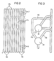
- FIG. 2 A continuous steam generator is shown in FIG. 2 in US Pat. No. 2,982,267 shown, in which a first evaporator pipe in lower part of the first throttle cable on the flow medium side Type bulkhead heating surface immediately downstream and in one Space within the first throttle cable above one Combustion chamber is arranged.
- this heating surface is a combination of evaporator heating surface and superheater heating surface and only the evaporator part is the water-steam separator downstream.
- the invention is therefore based on the object in To specify the two-pass type of continuous steam generator, which is particularly long even with frequent starting operations Has lifespan.
- a particularly inexpensive method is said to start up such a once-through steam generator can be specified.
- the invention is based on the consideration that for a particularly long lifespan of the once-through steam generator too in the case of frequent starting operations, the thermal tensions between the Boundary wall of the first throttle cable and the walls of the horizontal throttle cable should be kept particularly low. To the temperature differences between the immediately before starting the burner, fill it with cold feed water, the steam generator tubes assigned to the first throttle cable and the with a warm start still relatively hot walls of the Horizontal throttle cable must be kept particularly low.
- the outlet manifold is the one of the first gas train assigned steam generator tubes in such a dimensioned Height arranged that a direct contact of the front steam generator tubes filled with cold feed water with the walls of the horizontal throttle cable still hot during a warm start is avoided.
- Steam generator pipes already during start-up Heating surfaces provided for steam generation are particularly large dimensioned. For this is the one that forms the evaporator heating surface Steam generator pipes as additional to steam generation provided heating surface downstream of the bulkhead heating surface.
- the bulkhead heating surface is within a room area of the first throttle cable above that provided in the first gas cable Combustion chamber arranged.
- the bulkhead heating surface is therefore in one especially when starting up the continuous steam generator highly heated room area arranged and contributes in particular to a large extent for steam generation.
- too a large one when the continuous steam generator is started up Amount of steam generated, which leads to a particularly effective cooling of the steam generator tubes provided as evaporator tubes downstream steam generator tubes designed as superheater tubes contributes.
- the throttle cable advantageously an approximately horizontal Dividing line between when filled with water and provided with steam-filled steam generator pipes when starting up.
- This dividing line can be designed in this way be that the thermal stresses occurring at this point are kept particularly low. A meeting of the Start-up of differently cooled heating surfaces in the transition area from the first throttle cable to the horizontal throttle cable thus safely avoided.
- a steam-side one Outlet of the water-steam separator to an inlet header for a number of others designed as superheater tubes Steam generator pipes connected, these steam generator pipes the upper part of the perimeter wall of the first Form the throttle cable, and this inlet collector in one lower compared to the lower edge of the horizontal throttle cable Height is arranged.
- the flow medium throughput is advantageously achieved by the steam generator tubes forming the evaporator heating surface after its lowering proportional to the heat output of the Continuous steam generator set.
- the advantages achieved with the invention are in particular in that by at a height between the first Accelerator cable assigned burners and the lower edge of the horizontal throttle cable arranged outlet collector of the evaporator heating surface an almost horizontal dividing line between the Start-up with water-filled steam generator tubes and with Steam-filled steam generator tubes in one to avoid them created particularly favorable area of thermal stresses is.
- the occurrence of thermal stress in the transition area from the first accelerator cable to the horizontal accelerator cable safely avoided, so that the once-through steam generator is a special long service life even with frequent starts having.
- the bulkhead heating surface also ensures that when starting, a sufficiently large evaporator heating surface is available to a particularly high Generate steam mass flow and thus safe cooling to ensure all steam generator tubes.
- the continuous steam generator according to Figure 1 comprises a number of burners 2 for a fossil fuel, which are shown in FIG are shown schematically based on their main axes.
- the Burners 2 are arranged in a combustion chamber 4, through a lower part of the peripheral wall 6 of a vertically arranged first throttle cable 8 is formed.
- the surrounding wall 6 goes at the lower end of the first throttle cable 8 formed by it into a funnel-shaped bottom 10.
- the continuous steam generator 1 according to FIG. 1 is of the two-pass type executed.
- the first throttle cable 8 is for combustion of the fossil fuel fuel gas a horizontal throttle cable 12 is followed by a second throttle cable 14.
- the second throttle cable 14 is also arranged vertically.
- the peripheral wall 6 of the first throttle cable 8 is made of steam generator tubes 16.17 built that gas-tight on its long sides connected to each other, for example welded.
- the surrounding wall 18 of the second throttle cable is of an analog design 14 also from steam generator tubes, not shown built up on their long sides gastight with each other are connected.
- the horizontal throttle cable 12 in turn comprises a number of steam generator tubes, not shown, to the surrounding wall, which is also gastight arranged heating surfaces 20 are combined.
- are the surrounding wall 6 of the first gas train 8 forming steam generator tubes 16, 17 vertically arranged.
- the steam generator tubes 16, 17 but also rising obliquely in the manner of a screw winding be arranged around the first throttle cable.
- the surrounding wall 6 of the first in a lower area Accelerator cable 8 forming steam generator tubes 16 are used as evaporator tubes designed and to a number of evaporator heating surfaces 22 summarized, each part of the perimeter wall 6 of the first throttle cable 8.
- the steam generator pipes 16 of each evaporator heating surface 22 are for the flow of Water connected as a flow medium in parallel and are with their entry ends to a common, not shown Entry collectors and with their exit ends to a common one Outlet collector 24 connected.
- the outlet header 24 is one on the flow medium side Bulkhead heating surface 26 connected.
- the bulkhead heating surface 26 is from a number of, not shown, for the flow of the flow medium connected in parallel Steam generator tubes built, the input side to one common entrance collector 28 and on the exit side to one common outlet collector 30 are connected.
- the the Bulb heating surface 26 forming steam generator tubes are tight arranged side by side in a plane and form a number of plate-like heating surfaces within the first throttle cable 8 or the horizontal throttle cable 12 suspended are.
- the bulkhead heating surface 26 is a water-steam separation device on the flow medium side 34 downstream, the steam side Outlet 36 to an inlet header 38 for a number further, only indicated in Figure 1 for a better overview Steam generator tubes 17 is connected.
- the others Steam generator tubes 17 are designed as superheater tubes and to a number of superheater heating surfaces, not shown summarized the 32 in the upper room Form the peripheral wall 6 of the first throttle cable 8.
- In the flow path between the outlet header 24 and the water-steam separator 34 is bypassing the bulkhead heating surface 26 also one that can be shut off with a bypass valve 40 Bypass line 42 switched.
- the steam generator tubes 16,17 in an area at the level of the outlet collector 24 and the Entry collector 38 in a toothed arrangement in the surrounding wall 6 of the first throttle cable 8 is mounted.
- the surrounding wall 6 of the first throttle cable 8 forming steam generator tubes 16 in two groups of Steam generator tubes 16a and 16b combined the a larger group assigned to the first group Have length than that assigned to the second group Steam generator tubes 16b.
- Each of the comparatively shorter steam generator tubes 17b is above a comparatively longer one Steam generator tube 16a arranged, each of the comparatively longer steam generator tubes 17a above each a comparatively shorter steam generator tube 16b is.
- both open out comparatively shorter steam generator tubes 16b as well comparatively longer steam generator tubes 16a in the outlet header 24, being for the comparatively longer Steam generator pipes 16a each have a feed pipe section 16c is provided.
- Both the comparatively shorter ones are analogous Steam generator tubes 17a as well as the comparatively longer ones Steam generator tubes 17b connected to the inlet header 38.
- the other steam generator tubes 17 on the flow medium side in the horizontal gas flue 12 arranged heating surfaces 20 the surrounding wall 18 of the second throttle cable 14 forming steam generator tubes downstream.
- Both the heating surfaces 20 of the horizontal throttle cable 12 forming steam generator tubes as well as the surrounding wall 18 of the second throttle cable 14 forming steam generator tubes are intended as superheater tubes and with regard to their interpretation depending on the location of their arrangement Adjusted heating gas and flow medium parameters.
- the one as superheater tubes trained further steam generator tubes 17 upstream together Entry collector 38 is at a height between the outlet header 24 and the lower edge 44 of the Horizontal throttle cable arranged, that is in a compared to Outlet collector 24 larger and compared to the lower edge 44 of the horizontal throttle cable 12 lower height.
- the bulkhead heating surface 26 also ensures that when starting up a sufficiently large evaporator heating surface Is available to ensure safe cooling of the steam generator tubes 16 downstream of the flow medium, steam generator tubes designed as superheater tubes 17 to ensure.
- evaporator heating surface Is available to ensure safe cooling of the steam generator tubes 16 downstream of the flow medium, steam generator tubes designed as superheater tubes 17 to ensure.
- Through the bulkhead heating surface 26 is above also a buffer for when starting off the evaporated heating surface 22 expelled undevaporated flow medium created. That got into the bulkhead heating surface 26 undevaporated flow medium evaporates there, so that the water output of the once-through steam generator 1 when starting up and the associated heat loss is particularly low.
Landscapes
- Engineering & Computer Science (AREA)
- Physics & Mathematics (AREA)
- Thermal Sciences (AREA)
- Mechanical Engineering (AREA)
- General Engineering & Computer Science (AREA)
- Chemical & Material Sciences (AREA)
- Combustion & Propulsion (AREA)
- Control Of Steam Boilers And Waste-Gas Boilers (AREA)
- Heat-Exchange Devices With Radiators And Conduit Assemblies (AREA)
- Treating Waste Gases (AREA)
Description
- FIG 1
- schematisch einen Durchlaufdampferzeuger in Zweizugbauart,
- FIG 2
- einen Ausschnitt aus einer Umfassungswand des Durchlaufdampferzeugers nach Figur 1, und
- FIG 3
- einen Eintrittssammler und einen Austrittssammler des Durchlaufdampferzeugers nach Figur 1.
Claims (4)
- Durchlaufdampferzeuger (1) mit einem ersten Gaszug (8), dem heizgasseitig über einen Horizontalgaszug (12) ein zweiter Gaszug (14) nachgeschaltet ist, wobei eine Anzahl von für die Durchströmung eines Strömungsmediums parallel geschalteten Dampferzeugerrohren (16) miteinander zu einer gasdichten Verdampferheizfläche (22) verbunden sind, die Teil einer Umfassungswand (6) des ersten Gaszuges (8) ist, und wobei die die Verdampferheizfläche (22) bildenden Dampferzeugerrohre (16) ausgangsseitig in einen ihnen gemeinsamen, in einer im Vergleich zu einer Unterkante (44) des Horizontalgaszuges (12) niedrigeren Höhe angeordneten Austrittssammler (24) münden,
dadurch gekennzeichnet, daß dem Austrittssammler (24) strömungsmediumsseitig eine Schottheizfläche (26) unmittelbar nachgeschaltet ist, wobei die Schottheizfläche (26) in einem Raumbereich (32) innerhalb des ersten Gaszuges (8) oberhalb einer Brennkammer (4) angeordnet ist und wobei der Schottheizfläche (26) strömungsmediumsseitig eine Wasser-Dampf-Trennvorrichtung (34) nachgeschaltet ist. - Durchlaufdampferzeuger (1) nach Anspruch 3, bei dem ein dampfseitiger Auslaß (36) der Wasser-Dampf-Trennvorrichtung (34) an einen Eintrittssammler (38) für eine Anzahl weiterer, in der Umfassungswand (6) des ersten Gaszugs (8) geführter Dampferzeugerrohre (17) angeschlossen ist, der in einer im Vergleich zur Unterkante (44) des Horizontalgaszuges (12) geringeren Höhe angeordnet ist.
- Verfahren zum Anfahren eines Durchlaufdampferzeugers (1) nach einem der Ansprüche 1 oder 2, bei dem nach dem Einsetzen eines Wasserausstoßes aus den die Verdampferheizfläche (22) bildenden Dampferzeugerrohren (16), deren Strömungsmediumsdurchsatz vorübergehend abgesenkt wird.
- Verfahren nach Anspruch 5, bei dem der Strömungsmediumsdurchsatz durch die die Verdampferheizfläche (22) bildenden Dampferzeugerrohre (16) nach seiner Absenkung proportional zur Feuerwärmeleistung des Durchlaufdampferzeugers (1) eingestellt wird.
Applications Claiming Priority (3)
| Application Number | Priority Date | Filing Date | Title |
|---|---|---|---|
| DE19717158 | 1997-04-23 | ||
| DE19717158A DE19717158C2 (de) | 1997-04-23 | 1997-04-23 | Durchlaufdampferzeuger und Verfahren zum Anfahren eines Durchlaufdampferzeugers |
| PCT/DE1998/001055 WO1998048217A1 (de) | 1997-04-23 | 1998-04-14 | Durchlaufdampferzeuger und verfahren zum anfahren eines durchlaufdampferzeugers |
Publications (2)
| Publication Number | Publication Date |
|---|---|
| EP0977964A1 EP0977964A1 (de) | 2000-02-09 |
| EP0977964B1 true EP0977964B1 (de) | 2002-08-28 |
Family
ID=7827504
Family Applications (1)
| Application Number | Title | Priority Date | Filing Date |
|---|---|---|---|
| EP98931919A Expired - Lifetime EP0977964B1 (de) | 1997-04-23 | 1998-04-14 | Durchlaufdampferzeuger und verfahren zum anfahren eines durchlaufdampferzeugers |
Country Status (9)
| Country | Link |
|---|---|
| US (1) | US6192837B1 (de) |
| EP (1) | EP0977964B1 (de) |
| KR (1) | KR100543383B1 (de) |
| CN (1) | CN1126905C (de) |
| CA (1) | CA2287177A1 (de) |
| DE (2) | DE19717158C2 (de) |
| DK (1) | DK0977964T3 (de) |
| RU (1) | RU2188357C2 (de) |
| WO (1) | WO1998048217A1 (de) |
Families Citing this family (20)
| Publication number | Priority date | Publication date | Assignee | Title |
|---|---|---|---|---|
| EP1288567A1 (de) * | 2001-08-31 | 2003-03-05 | Siemens Aktiengesellschaft | Verfahren zum Anfahren eines Dampferzeugers mit einem in einer annähernd horizontalen Heizgasrichtung durchströmbaren Heizgaskanal und Dampferzeuger |
| US20050072379A1 (en) * | 2003-08-15 | 2005-04-07 | Jupiter Oxygen Corporation | Device and method for boiler superheat temperature control |
| WO2006054990A1 (en) * | 2004-11-12 | 2006-05-26 | Jupiter Oxygen Corporation | Device and method for boiler superheat temperature control |
| EP1701091A1 (de) * | 2005-02-16 | 2006-09-13 | Siemens Aktiengesellschaft | Durchlaufdampferzeuger |
| US7516620B2 (en) | 2005-03-01 | 2009-04-14 | Jupiter Oxygen Corporation | Module-based oxy-fuel boiler |
| EP1710498A1 (de) * | 2005-04-05 | 2006-10-11 | Siemens Aktiengesellschaft | Dampferzeuger |
| KR100902538B1 (ko) | 2007-05-15 | 2009-06-15 | 주피터 옥시젠 코포레이션 | 보일러 및 보일러의 버너 개조 방법 |
| EP2065641A3 (de) * | 2007-11-28 | 2010-06-09 | Siemens Aktiengesellschaft | Verfahren zum Betrieben eines Durchlaufdampferzeugers sowie Zwangdurchlaufdampferzeuger |
| EP2119880A1 (de) | 2008-02-15 | 2009-11-18 | Siemens Aktiengesellschaft | Verfahren zum Anfahren eines Durchdampferzeugers |
| EP2194320A1 (de) * | 2008-06-12 | 2010-06-09 | Siemens Aktiengesellschaft | Verfahren zum Betreiben eines Durchlaufdampferzeugers sowie Zwangdurchlaufdampferzeuger |
| EP2180250A1 (de) * | 2008-09-09 | 2010-04-28 | Siemens Aktiengesellschaft | Durchlaufdampferzeuger |
| EP2204611A1 (de) * | 2008-09-09 | 2010-07-07 | Siemens Aktiengesellschaft | Abhitzedampferzeuger |
| EP2180251A1 (de) * | 2008-09-09 | 2010-04-28 | Siemens Aktiengesellschaft | Durchlaufdampferzeuger |
| EP2182278A1 (de) * | 2008-09-09 | 2010-05-05 | Siemens Aktiengesellschaft | Durchlaufdampferzeuger |
| DE102009024587A1 (de) * | 2009-06-10 | 2010-12-16 | Siemens Aktiengesellschaft | Durchlaufverdampfer |
| DE102009040250B4 (de) * | 2009-09-04 | 2015-05-21 | Alstom Technology Ltd. | Zwangdurchlaufdampferzeuger für den Einsatz von Dampftemperaturen von über 650 Grad C |
| US20120012036A1 (en) * | 2010-07-15 | 2012-01-19 | Shaw John R | Once Through Steam Generator |
| DE102013215457A1 (de) * | 2013-08-06 | 2015-02-12 | Siemens Aktiengesellschaft | Durchlaufdampferzeuger in Zweizugkesselbauweise |
| CN104154513A (zh) * | 2014-04-23 | 2014-11-19 | 盐城市锅炉制造有限公司 | 罐式煅烧炉的余热锅炉 |
| CN112162484B (zh) * | 2020-09-24 | 2023-03-14 | 华北电力大学(保定) | 一种适用于深调峰运行的火电机组柔性协调控制方法 |
Family Cites Families (18)
| Publication number | Priority date | Publication date | Assignee | Title |
|---|---|---|---|---|
| US3003479A (en) * | 1952-10-11 | 1961-10-10 | Duerrwerke Ag | Steam and air boiler with heating surface of smallest load |
| DE1015818B (de) * | 1955-11-15 | 1957-09-19 | Siemens Ag | Zwangstrom-Dampferzeuger fuer sehr hohe Betriebsdruecke, insbesondere fuer ueberkritischen Druck |
| DE1263783B (de) * | 1956-04-25 | 1968-03-21 | Siemens Ag | Verfahren zur Inbetriebnahme von Zwangdurchlaufkesseln |
| US2982267A (en) * | 1956-07-11 | 1961-05-02 | Sulzer Ag | High pressure steam plant |
| DE1263873B (de) | 1963-11-28 | 1968-03-21 | Sfim | Einrichtung zur Zaehlung von Fahrzeugen mittels hochfrequenter elektromagnetischer Wellen |
| US3927646A (en) * | 1965-04-13 | 1975-12-23 | Babcock & Wilcox Co | Vapor generator |
| BE756407A (fr) * | 1969-09-23 | 1971-03-22 | Sulzer Ag | Procede de mise en marche d'un generateur de vapeur |
| US3771498A (en) * | 1972-01-03 | 1973-11-13 | Foster Wheeler Corp | Furnace circuit for variable pressure once-through generator |
| US4000720A (en) * | 1975-08-18 | 1977-01-04 | The Babcock & Wilcox Company | Vapor generator |
| DE2557427A1 (de) * | 1975-12-19 | 1977-06-30 | Kraftwerk Union Ag | Schaltung einer feuerraumnase bei einem durchlaufkessel mit gasdicht verschweissten waenden in zweizugbauweise |
| US4116168A (en) * | 1977-04-28 | 1978-09-26 | Foster Wheeler Energy Corporation | Vapor generating system utilizing integral separators and angularly arranged furnance boundary wall fluid flow tubes |
| US4290389A (en) * | 1979-09-21 | 1981-09-22 | Combustion Engineering, Inc. | Once through sliding pressure steam generator |
| US4294200A (en) * | 1979-12-06 | 1981-10-13 | Foster Wheeler Energy Corporation | Variable pressure vapor generator utilizing crossover circuitry for the furnace boundary wall fluid flow tubes |
| EP0308728B1 (de) * | 1987-09-21 | 1991-06-05 | Siemens Aktiengesellschaft | Verfahren zum Betreiben eines Durchlaufdampferzeugers |
| RU2039318C1 (ru) * | 1992-05-22 | 1995-07-09 | Акционерное общество "Белгородский завод энергетического машиностроения" | Котел |
| DE19504308C1 (de) * | 1995-02-09 | 1996-08-08 | Siemens Ag | Verfahren und Vorrichtung zum Anfahren eines Durchlaufdampferzeugers |
| DE19528438C2 (de) * | 1995-08-02 | 1998-01-22 | Siemens Ag | Verfahren und System zum Anfahren eines Durchlaufdampferzeugers |
| US5713311A (en) * | 1996-02-15 | 1998-02-03 | Foster Wheeler Energy International, Inc. | Hybrid steam generating system and method |
-
1997
- 1997-04-23 DE DE19717158A patent/DE19717158C2/de not_active Expired - Fee Related
-
1998
- 1998-04-14 EP EP98931919A patent/EP0977964B1/de not_active Expired - Lifetime
- 1998-04-14 CA CA002287177A patent/CA2287177A1/en not_active Abandoned
- 1998-04-14 KR KR1019997009683A patent/KR100543383B1/ko not_active Expired - Fee Related
- 1998-04-14 RU RU99124764/06A patent/RU2188357C2/ru not_active IP Right Cessation
- 1998-04-14 CN CN98803130A patent/CN1126905C/zh not_active Expired - Fee Related
- 1998-04-14 WO PCT/DE1998/001055 patent/WO1998048217A1/de not_active Ceased
- 1998-04-14 DK DK98931919T patent/DK0977964T3/da active
- 1998-04-14 DE DE59805320T patent/DE59805320D1/de not_active Expired - Fee Related
-
1999
- 1999-10-25 US US09/426,421 patent/US6192837B1/en not_active Expired - Fee Related
Also Published As
| Publication number | Publication date |
|---|---|
| DE19717158A1 (de) | 1998-11-05 |
| EP0977964A1 (de) | 2000-02-09 |
| RU2188357C2 (ru) | 2002-08-27 |
| KR20010012074A (ko) | 2001-02-15 |
| DK0977964T3 (da) | 2002-12-30 |
| DE19717158C2 (de) | 1999-11-11 |
| WO1998048217A1 (de) | 1998-10-29 |
| CN1249807A (zh) | 2000-04-05 |
| KR100543383B1 (ko) | 2006-01-20 |
| DE59805320D1 (de) | 2002-10-02 |
| CA2287177A1 (en) | 1998-10-29 |
| CN1126905C (zh) | 2003-11-05 |
| US6192837B1 (en) | 2001-02-27 |
Similar Documents
| Publication | Publication Date | Title |
|---|---|---|
| EP0977964B1 (de) | Durchlaufdampferzeuger und verfahren zum anfahren eines durchlaufdampferzeugers | |
| EP0349834B1 (de) | Durchlaufdampferzeuger | |
| DE19929088C1 (de) | Fossilbeheizter Dampferzeuger mit einer Entstickungseinrichtung für Heizgas | |
| EP0657010B2 (de) | Dampferzeuger | |
| EP0617778A1 (de) | Fossil befeuerter durchlaufdampferzeuger. | |
| EP2321578B1 (de) | Durchlaufdampferzeuger | |
| EP0842381A1 (de) | Verfahren und system zum anfahren eines durchlaufdampferzeugers | |
| DE19914761C1 (de) | Fossilbeheizter Durchlaufdampferzeuger | |
| EP1166015B1 (de) | Fossilbeheizter durchlaufdampferzeuger | |
| EP0808440B1 (de) | Verfahren und vorrichtung zum anfahren eines durchlaufdampferzeugers | |
| EP1141625A1 (de) | Fossilbeheizter durchlaufdampferzeuger | |
| EP1512905A1 (de) | Durchlaufdampferzeuger sowie Verfahren zum Betreiben des Durchlaufdampferzeugers | |
| WO2006087272A2 (de) | Durchlaufdampferzeuger | |
| DE102010038883C5 (de) | Zwangdurchlaufdampferzeuger | |
| EP1794495A1 (de) | Fossil beheizter durchlaufdampferzeuger | |
| EP0812407B1 (de) | Verfahren und system zum anfahren eines durchlaufdampferzeugers | |
| WO2005050089A1 (de) | Durchlaufdampferzeuger | |
| DE19507335C2 (de) | Dampferzeuger | |
| DE102010038885A1 (de) | Zwangdurchlaufdampferzeuger | |
| DE4229629A1 (de) | Dampferzeuger | |
| WO1998048218A1 (de) | Durchlaufdampferzeuger | |
| EP0349767A1 (de) | Zwangdurchlaufdampferzeuger |
Legal Events
| Date | Code | Title | Description |
|---|---|---|---|
| PUAI | Public reference made under article 153(3) epc to a published international application that has entered the european phase |
Free format text: ORIGINAL CODE: 0009012 |
|
| 17P | Request for examination filed |
Effective date: 19991019 |
|
| AK | Designated contracting states |
Kind code of ref document: A1 Designated state(s): CH DE DK ES FR GB LI SE |
|
| 17Q | First examination report despatched |
Effective date: 20010621 |
|
| GRAG | Despatch of communication of intention to grant |
Free format text: ORIGINAL CODE: EPIDOS AGRA |
|
| GRAG | Despatch of communication of intention to grant |
Free format text: ORIGINAL CODE: EPIDOS AGRA |
|
| GRAH | Despatch of communication of intention to grant a patent |
Free format text: ORIGINAL CODE: EPIDOS IGRA |
|
| GRAH | Despatch of communication of intention to grant a patent |
Free format text: ORIGINAL CODE: EPIDOS IGRA |
|
| GRAA | (expected) grant |
Free format text: ORIGINAL CODE: 0009210 |
|
| AK | Designated contracting states |
Kind code of ref document: B1 Designated state(s): CH DE DK ES FR GB LI SE |
|
| PG25 | Lapsed in a contracting state [announced via postgrant information from national office to epo] |
Ref country code: FR Free format text: LAPSE BECAUSE OF NON-PAYMENT OF DUE FEES Effective date: 20020828 |
|
| REG | Reference to a national code |
Ref country code: GB Ref legal event code: FG4D Free format text: NOT ENGLISH |
|
| REG | Reference to a national code |
Ref country code: CH Ref legal event code: EP |
|
| REF | Corresponds to: |
Ref document number: 59805320 Country of ref document: DE Date of ref document: 20021002 |
|
| PG25 | Lapsed in a contracting state [announced via postgrant information from national office to epo] |
Ref country code: SE Free format text: LAPSE BECAUSE OF FAILURE TO SUBMIT A TRANSLATION OF THE DESCRIPTION OR TO PAY THE FEE WITHIN THE PRESCRIBED TIME-LIMIT Effective date: 20021128 |
|
| GBT | Gb: translation of ep patent filed (gb section 77(6)(a)/1977) |
Effective date: 20021126 |
|
| REG | Reference to a national code |
Ref country code: DK Ref legal event code: T3 |
|
| PG25 | Lapsed in a contracting state [announced via postgrant information from national office to epo] |
Ref country code: ES Free format text: LAPSE BECAUSE OF FAILURE TO SUBMIT A TRANSLATION OF THE DESCRIPTION OR TO PAY THE FEE WITHIN THE PRESCRIBED TIME-LIMIT Effective date: 20030228 |
|
| PG25 | Lapsed in a contracting state [announced via postgrant information from national office to epo] |
Ref country code: LI Free format text: LAPSE BECAUSE OF NON-PAYMENT OF DUE FEES Effective date: 20030430 Ref country code: CH Free format text: LAPSE BECAUSE OF NON-PAYMENT OF DUE FEES Effective date: 20030430 |
|
| EN | Fr: translation not filed | ||
| PLBE | No opposition filed within time limit |
Free format text: ORIGINAL CODE: 0009261 |
|
| STAA | Information on the status of an ep patent application or granted ep patent |
Free format text: STATUS: NO OPPOSITION FILED WITHIN TIME LIMIT |
|
| 26N | No opposition filed |
Effective date: 20030530 |
|
| REG | Reference to a national code |
Ref country code: CH Ref legal event code: PL |
|
| PGFP | Annual fee paid to national office [announced via postgrant information from national office to epo] |
Ref country code: GB Payment date: 20060411 Year of fee payment: 9 |
|
| PGFP | Annual fee paid to national office [announced via postgrant information from national office to epo] |
Ref country code: DK Payment date: 20060418 Year of fee payment: 9 |
|
| PGFP | Annual fee paid to national office [announced via postgrant information from national office to epo] |
Ref country code: DE Payment date: 20060619 Year of fee payment: 9 |
|
| REG | Reference to a national code |
Ref country code: DK Ref legal event code: EBP |
|
| GBPC | Gb: european patent ceased through non-payment of renewal fee |
Effective date: 20070414 |
|
| PG25 | Lapsed in a contracting state [announced via postgrant information from national office to epo] |
Ref country code: DE Free format text: LAPSE BECAUSE OF NON-PAYMENT OF DUE FEES Effective date: 20071101 |
|
| PG25 | Lapsed in a contracting state [announced via postgrant information from national office to epo] |
Ref country code: GB Free format text: LAPSE BECAUSE OF NON-PAYMENT OF DUE FEES Effective date: 20070414 Ref country code: DK Free format text: LAPSE BECAUSE OF NON-PAYMENT OF DUE FEES Effective date: 20070430 |