EP0977610B1 - Ensemble de sonde ureterale a chambre de lubrification integree - Google Patents
Ensemble de sonde ureterale a chambre de lubrification integree Download PDFInfo
- Publication number
- EP0977610B1 EP0977610B1 EP99934246A EP99934246A EP0977610B1 EP 0977610 B1 EP0977610 B1 EP 0977610B1 EP 99934246 A EP99934246 A EP 99934246A EP 99934246 A EP99934246 A EP 99934246A EP 0977610 B1 EP0977610 B1 EP 0977610B1
- Authority
- EP
- European Patent Office
- Prior art keywords
- catheter
- receptacle
- catheter assembly
- chamber
- lubrication chamber
- Prior art date
- Legal status (The legal status is an assumption and is not a legal conclusion. Google has not performed a legal analysis and makes no representation as to the accuracy of the status listed.)
- Expired - Lifetime
Links
Images


Classifications
-
- A—HUMAN NECESSITIES
- A61—MEDICAL OR VETERINARY SCIENCE; HYGIENE
- A61M—DEVICES FOR INTRODUCING MEDIA INTO, OR ONTO, THE BODY; DEVICES FOR TRANSDUCING BODY MEDIA OR FOR TAKING MEDIA FROM THE BODY; DEVICES FOR PRODUCING OR ENDING SLEEP OR STUPOR
- A61M25/00—Catheters; Hollow probes
- A61M25/01—Introducing, guiding, advancing, emplacing or holding catheters
- A61M25/0105—Steering means as part of the catheter or advancing means; Markers for positioning
- A61M25/0111—Aseptic insertion devices
-
- A—HUMAN NECESSITIES
- A61—MEDICAL OR VETERINARY SCIENCE; HYGIENE
- A61M—DEVICES FOR INTRODUCING MEDIA INTO, OR ONTO, THE BODY; DEVICES FOR TRANSDUCING BODY MEDIA OR FOR TAKING MEDIA FROM THE BODY; DEVICES FOR PRODUCING OR ENDING SLEEP OR STUPOR
- A61M25/00—Catheters; Hollow probes
- A61M25/0043—Catheters; Hollow probes characterised by structural features
- A61M2025/0062—Catheters; Hollow probes characterised by structural features having features to improve the sliding of one part within another by using lubricants or surfaces with low friction
-
- A—HUMAN NECESSITIES
- A61—MEDICAL OR VETERINARY SCIENCE; HYGIENE
- A61M—DEVICES FOR INTRODUCING MEDIA INTO, OR ONTO, THE BODY; DEVICES FOR TRANSDUCING BODY MEDIA OR FOR TAKING MEDIA FROM THE BODY; DEVICES FOR PRODUCING OR ENDING SLEEP OR STUPOR
- A61M25/00—Catheters; Hollow probes
- A61M25/0017—Catheters; Hollow probes specially adapted for long-term hygiene care, e.g. urethral or indwelling catheters to prevent infections
-
- A—HUMAN NECESSITIES
- A61—MEDICAL OR VETERINARY SCIENCE; HYGIENE
- A61M—DEVICES FOR INTRODUCING MEDIA INTO, OR ONTO, THE BODY; DEVICES FOR TRANSDUCING BODY MEDIA OR FOR TAKING MEDIA FROM THE BODY; DEVICES FOR PRODUCING OR ENDING SLEEP OR STUPOR
- A61M25/00—Catheters; Hollow probes
- A61M25/002—Packages specially adapted therefor ; catheter kit packages
Definitions
- the present invention relates to a self-contained catheter assembly comprising: a receptacle comprising two opposed flexible walls extending from a distal end to a proximal end, a main chamber formed between the flexible walls, and an exit formed in the distal end of the receptacle, said exit being from the lubrication chamber; a lubricating material, said lubricating material being disposed in a lubrication chamber which is formed between the flexible walls, so as to form a self-lubricating catheter assembly; a catheter disposed within the receptacle; and a passage separating the main chamber and the lubrication chamber, the passage being formed between the flexible walls and allowing the catheter to pass therethrough.
- Such a catheter assembly is known from WO-A-98/06642.
- Pre-lubricated, self-contained urinary catheters are useful to provide a cleaner, less time consuming procedure. Catheter handling is reduced, as well as the risk of infection.
- self-contained catheters are contained within a flexible receptacle which serves to store the catheter before use and collects the urine during use of the catheter.
- An introducer provided at an exit of the receptacle, aids introduction of the catheter into the urethra.
- the catheter is precoated with a lubricant, which eliminates the need for manual lubrication of the catheter by a user and, since the lubricated catheter is contained within the receptacle until use, incidental contact between the lubricant and the user is minimized.
- the distal end of the catheter is introduced into the urethra using the introducer.
- the catheter is advanced by gripping the catheter through the receptacle and moving the catheter with one hand until the hand reaches the top of the receptacle.
- the catheter is held in this position with the other hand while the receptacle is straightened out. Then the catheter is advanced another distance. The user proceeds in this manner until the catheter reaches the bladder and urine starts to flow.
- a disadvantage of such a prelubricated, self-contained catheter is that the lubricant can become dispersed over the interior of the receptacle, causing the walls of the receptacle to stick together. This can make it difficult to advance the catheter and wastes lubricant. Additionally, it can be difficult to hold the receptacle and guide .the catheter at the same time, particularly if a patient is attempting self-catheterization.
- Document WO 98/06642 discloses a prelubricated urinary catheter and package assembly for use in draining the bladder through the urethra comprising a package defining an elongate sealed catheter receiving chamber carrying a urinary catheter with a guide arrangement within the chamber to guide the catheter as it extends out of the package. Also disclosed is an arrangement to hold the catheter with respect to a guide so as to prevent inadvertent movement of the catheter with respect to the guide. Also disclosed is the method of fabricating the assembly and the method of using the assembly.
- Document AT 369 994 B discloses an aseptic urethral catheter unit.
- the unit includes a receptacle and a catheter. Between opposed side edges of the receptacle, two opposed angles are disposed providing a connection between a lower chamber and an upper chamber. Between the angles, a centered opening is provided containing a tube-shaped guidance. In order to facilitate the bushing of the catheter through the guidance, a lubricant may be used.
- the present invention provides a self-contained, self-lubricating catheter assembly having a receptacle containing a catheter.
- the receptacle is formed of two opposed flexible walls extending from a distal end to a proximal end.
- a main chamber and a lubrication chamber are formed between the flexible walls.
- a passage separates the main chamber and the lubrication chamber, and an exit from the lubrication chamber is formed in the distal end of the receptacle.
- a lubricating material or lubricant is provided in the lubrication chamber. As the catheter is advanced through the lubrication chamber, it picks up lubricant.
- a catheter grasping mechanism is located proximate to and preferably within the exit.
- the catheter grasping mechanism has a passageway therethrough sized to allow the catheter to pass through.
- the user can grasp and hold the catheter by squeezing the grasping mechanism with the fingers to retain the catheter in an advanced position.
- a catheter engaging device may expend partially into the passageway of the grasping mechanism and be configured to permit advancement of the catheter out of the receptacle and resist movement of the catheter back into the receptacle.
- the catheter engaging device may comprise tabs extending radially inwardly and distally from walls of the passageway. Inwardly extending protrusions or a user-accessible dial with external teeth to engage the catheter may also be provided.
- the receptacle may also include one or more finger holes extending therethrough to allow the user to retain the receptacle on one or more fingers, thereby freeing the hand to more easily position the receptacle adjacent to the opening of the urethra while advancing the catheter.
- the user grips the catheter through the receptacle walls and directs it through the lubrication chamber and out the exit.
- the catheter is advanced by pushing it from the proximal end of the lubrication chamber.
- the user grasps the catheter through the grasping mechanism, lubrication chamber or introducer with a free hand to retain the catheter in the advanced position and straightens out the receptacle with the other hand.
- the user grips the catheter through the walls of the receptacle again and advances it another distance in the same manner.
- the catheter assembly is readily held and used.
- the lubricant is not smeared within the main chamber of the receptacle.
- the walls in the main chamber of the receptacle do not stick together, and the catheter can be more readily gripped and advanced through the walls.
- less lubricant is wasted.
- the finger holes allow a user to more readily position the receptacle and retain and guide the catheter at the same time, which is particularly useful for patients who must catheterize themselves.
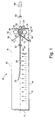
- a catheter assembly 10 includes a receptacle 12 having flexible walls made from an extruded or sheet material and extending from a proximal end 14 to a distal end 16.
- the receptacle includes a main chamber 18 adjacent the proximal end 14 and a lubrication chamber 20 adjacent the distal end 16 of the receptacle 12.
- a passage 22 separates the lubrication chamber 20 from the main chamber 18.
- a distal opening 24 from the lubrication chamber 20 forms an exit in the distal end 16 of the receptacle 12.
- the lubrication chamber 20 contains a lubricating gel or lubricant 26. Any suitable medical lubricating gel known in the art can be used.
- the passage 22 between the lubrication chamber 20 and the main chamber 18 is sufficiently narrow to minimize migration of the lubricant into the main chamber.
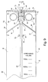
- a valve assembly 27, shown in Fig. 9, can be located within the passage 22 to further minimize migration of the lubricant.
- a catheter 28 is disposed within the receptacle 12.
- the catheter is typically either a red rubber or a vinyl catheter, as is known in the art.
- the catheter is retained in the main chamber 18.
- a user grasps the catheter through the flexible walls of the receptacle and threads the distal end 30 (see Fig. 10) of the catheter 28 through the passage 22 into the lubrication chamber 20 and out the exit 24.
- the proximal end 32 of the catheter may be widened or may include a retention device thereon to prevent the catheter from being pulled entirely out of the main chamber.
- the receptacle 12 is formed from an extruded material such as a polyethylene which is supplied as a tube cut to a suitable length and sealed at the proximal and distal ends 14, 16.
- the receptacle could be formed of one or more sheets of a flexible material sealed along seams extending between the proximal and distal ends.
- the seals at the proximal and distal ends and the seams extending between the ends may be formed in any suitable manner, such as by heat sealing, adhesive, stitching, RF welding, impulse welding, or chemical bonding.
- a sheet of a flexible material could be folded to form the proximal end 14 and sealed at the distal end and along sides extending between the proximal and distal ends.
- the lubrication chamber 20 and the distal end of the main chamber are defined by bond lines 31, 33 which seal opposed walls of the receptacle together.
- the lubrication chamber is formed by the bond line portions 34, 36 of bond lines 31, 33 respectively extending generally parallel from the distal end 16 of the receptacle 12.
- the bond lines converge at the proximal end of the lubrication chamber 20 to define the passage 22 between the lubrication chamber 20 and the main chamber 18.
- Bond line portions 38, 40 of bond lines 31, 33 respectively then diverge from the passage 22 toward the sides 42, 44 of the receptacle to form the distal end of the main chamber.
- the diverging bond line portions 38, 40 extend at an acute angle from the passage 22 toward the sides 42, 44 of the receptacle 12 to form a catheter guideway as illustrated in Figs. 1 and 9. This angle aids the user in guiding the distal end 30 of the catheter 28 toward the passage 22 to the lubrication chamber 20.
- the diverging bond line portions 38, 40 may also extend directly toward the sides 42, 44, i.e., parallel to the proximal and distal ends 14, 16 of the receptacle, if desired.
- a catheter guide channel 50 is also provided in the main chamber, which also functions as a catheter guideway.
- the guide channel is formed by a pair of short parallel bond lines 52, 54 sealing the opposed walls of the receptacle in a central region of the main chamber 18 and spaced from the passage 22 to the lubrication chamber 20.
- the guide channel 50 aids in locating the catheter 28 centrally within the main chamber, which is helpful when the user is directing the catheter into and through the lubrication chamber.
- the guide channel can also be used to hold the catheter outside of the lubrication chamber 20 prior to using the catheter.
- the bond lines defining the lubrication chamber, the distal end of the main chamber, and the catheter guide channel can be formed in any suitable manner, such as by heat sealing, adhesive,' stitching, RF welding, or impulse welding.
- the lubrication chamber can be provided as a separate component, such as a suitably sized bag or bladder sealed within the receptacle adjacent the exit 24; an opening on one end of the bag defines the passage 22 from the main chamber and another opening is located adjacent the exit 24.
- a catheter grasping mechanism 56 is located proximate and preferably within the exit 24 from the lubrication chamber 20 to permit advancement of the catheter 28 out of the receptacle 12 and resist slippage of the catheter back into the receptacle.
- the grasping mechanism comprises an insert 60 having a passageway 62 therethrough.
- the insert is fixedly located within the exit 24 in any suitable manner.
- the insert may include flanges or wings 64 protruding from opposed sides thereof and which are fixed, such as by heat sealing, within the bond line portions 34, 36 at the distal end of the lubrication chamber and within the bond line at the distal end 16 of the receptacle.
- the insert is formed of the same material as the receptacle (for example, polyethylene) to assist in bonding thereto.
- the insert may be fixed proximate the exit of the receptacle in any other suitable manner, as would be known in the art.
- the protrusion of the insert into the lubrication chamber is minimized to provide additional space for the lubricant therein.
- the user can grasp and hold the catheter by squeezing the grasping mechanism with the fingers to retain the catheter in an advanced position or by squeezing the catheter through the lubrication chamber.
- the catheter grasping mechanism also includes tabs 66 which extend radially inwardly from walls of the passageway 62 and distally toward the exit 68 of the passageway through the insert.
- tabs 66 which extend radially inwardly from walls of the passageway 62 and distally toward the exit 68 of the passageway through the insert.
- the walls 72 of the passageway 62 of the insert 60 are textured to provide a roughness which frictionally engages the catheter.
- the texture may comprise an all-over pattern or discrete protrusions 73 extending inwardly from walls of the passageway.
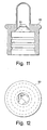
- a slot or aperture 74 is formed through the wall 72 of the insert 60.
- a dial or gear 76 having outwardly extending teeth 78 is rotatably mounted in the slot in the insert.
- the dial protrudes through the slot to extend into the passageway 62 in the insert a distance sufficient to frictionally engage the teeth against the catheter.
- the dial also protrudes outside the insert, where a user's finger can rotate the dial to advance the catheter.
- an introducer 80 to assist insertion of the catheter into the urethra may be placed over the insert 60, as is known in the art.
- the outer surface 82 of the insert 60 may be ribbed 'or otherwise textured to assist in frictionally retaining the introducer thereon (see particularly Fig. 10).
- a cap or cover 84 may be placed over the introducer during storage, also as known in the art.
- a catheter grasping mechanism having tabs 81 or other protrusions such as described above with respect to the embodiments illustrated in Figs. 5-8 can be formed within the introducer 80.
- the catheter can be grasped through the introducer by the user's fingers squeezing the introducer.
- Finger holes 86, 88 are provided in the regions 90, 92 of the receptacle 12 adjacent the sides of the lubrication chamber 20.
- one finger hole is provided in each side.
- the circumference of each finger hole may be reinforced in any suitable manner, such as by a bond line 94, which may be formed as the bond lines described above.
- the finger holes are particularly useful for self-catheterization. Although two finger holes are shown, it will be appreciated that a single finger hole or three or more finger holes could be provided if desired. Similarly, one or more finger holes can be provided in a receptacle that does not also include the lubrication chamber of the present invention.
- the user places a finger of one hand through each hole 86, 88 to suspend the receptacle 12.
- the remaining fingers of that hand can be used to hold the receptacle adjacent to the urethral opening.
- the other hand is free to manipulate the catheter 28 within the receptacle.
- the user grips the catheter through the flexible walls of the receptacle and threads the distal end 30 of the catheter through the passage 22 into the lubrication chamber 20 and out the exit 24.
- the outer surface of the catheter 28 picks up a sufficient amount of lubricant 26 to ease insertion of the catheter into the urethra.
- the walls of the receptacle do not stick together and it becomes easier for the user to manipulate the catheter through the receptacle walls.
- Catheter advancement is achieved by gripping the catheter with a first hand through the receptacle walls and pushing it from the proximal end of the lubrication chamber.
- the proximal end of the lubrication chamber reaches the distal end, the user releases the catheter.
- the user can retain the catheter in the advanced position by squeezing the catheter through the catheter grasping mechanism with the fingers of the other hand.
- the user can employ the fingers which extend through the two finger holes for this purpose.
- the catheter can be retained in the advanced position by the catheter engaging mechanism described above. The user then straightens out the receptacle with the first hand.
- the user grips the catheter through the walls of the receptacle again and advances it another distance until the proximal end of the lubrication chamber reaches the distal end. Additionally, compressing the lubrication chamber with each advance of the catheter acts as a pumping mechanism to force lubricant through the exit with the catheter. Once the distal end of the catheter reaches the patient's bladder, urine begins to flow and is collected in the main chamber of the receptacle.
- the receptacle can hold up to 1200 cc of liquid, although receptacles having larger or smaller volumes can be provided. Indicia indicating the volume of urine collected may be marked along a wall of the receptacle.
- the catheter assembly of the present invention is applicable to all sizes of catheters, from 6 to 26 French, and can be used for adults, children, males, and females.
Landscapes
- Health & Medical Sciences (AREA)
- Life Sciences & Earth Sciences (AREA)
- Biophysics (AREA)
- Pulmonology (AREA)
- Engineering & Computer Science (AREA)
- Anesthesiology (AREA)
- Biomedical Technology (AREA)
- Heart & Thoracic Surgery (AREA)
- Hematology (AREA)
- Animal Behavior & Ethology (AREA)
- General Health & Medical Sciences (AREA)
- Public Health (AREA)
- Veterinary Medicine (AREA)
- External Artificial Organs (AREA)
- Media Introduction/Drainage Providing Device (AREA)
- Infusion, Injection, And Reservoir Apparatuses (AREA)
- Materials For Medical Uses (AREA)
Claims (28)
- Ensemble de cathéter autonome (10) comprenant :caractérisé en ce que :un réceptacle (12) comprenant deux parois flexibles opposées s'étendant d'une extrémité distale (16) à une extrémité proximale (14), une chambre principale (18) formée entre les parois flexibles, et une sortie (24) formée dans l'extrémité distale (16) du réceptacle (12), ladite sortie (24) provient d'une chambre de lubrification (20):un matériau de lubrification (26), ledit matériau de lubrification (26) étant disposé dans la chambre de lubrification (20) qui est formée entre les parois flexibles, afin de former un ensemble de cathéter autolubrifiant (10) ;un cathéter (28) disposé dans le réceptacle (12) ; etun passage (22) séparant la chambre principale (18) et la chambre de lubrification (20), le passage (22) étant formé entre les parois flexibles et permettant au cathéter (28) de passer à travers ;le passage (22) est formé de sorte que le matériau lubrifiant (26) est retenu dans la chambre de lubrification (20) lorsque le cathéter est manipulé à l'intérieur du réceptacle (12), dans lequel la chambre de lubrification (20) est séparée de la chambre principale (16).
- Ensemble de cathéter autonome (10) selon la revendication 1, caractérisé en ce qu'au moins une partie du cathéter (28) est disposée à l'intérieur de la chambre principale (18) et l'ensemble comprend en outre :un mécanisme de préhension de cathéter (56) situé à l'intérieur de la sortie (24), le mécanisme de préhension de cathéter (56) ayant une voie de passage (62) à travers celui-ci dimensionnée pour permettre au cathéter (28) de passer à travers et opérationnelle pour retenir le cathéter (28) à l'intérieur.
- Ensemble de cathéter autonome (10) selon la revendication 1 ou 2, caractérisé en ce qu'au moins une partie des parois flexibles est prévue de manière adjacente à la chambre de lubrification (20) et en ce qu'au moins un trou de doigt (86, 88) est disposé à travers la partie des parois flexibles.
- Ensemble de cathéter selon la revendication 1, caractérisé en ce que la chambre de lubrification (20) est formée par des plans de joint (31, 33, 34, 36) rendant étanche les parois flexibles opposées.
- Ensemble de cathéter selon la revendication 4, caractérisé en ce que les plans de joint (31, 33, 34, 36) sont formés par thermosoudage, adhésif, couture, soudage par haute fréquence, soudage par impulsions thermiques, ou liaison chimique.
- Ensemble de cathéter selon la revendication 1, caractérisé en ce que le passage (22) entre la chambre de lubrification (20) et la chambre principale (18) est si large que le cathéter (28) peut passer à travers et est si étroite que la migration du matériau lubrifiant (26) de la chambre de lubrification (20) dans la chambre principale (18) est réduite.
- Ensemble de cathéter selon la revendication 1, caractérisé en ce que le réceptacle comprend en outre une voie de guidage de cathéter (50 ; 31, 33) disposée pour diriger le cathéter (28) vers la chambre de lubrification (20).
- Ensemble de cathéter selon la revendication 7, caractérisé en ce que la voie de guidage (50 ; 31, 33) comprend un canal de guidage (50) formé dans une région centrale de la chambre principale (18) et espacée de la chambre de lubrification (20).
- Ensemble de cathéter selon la revendication 8, caractérisé en ce que le canal de guidage (50) est formé par des plans de joint (52, 54) rendant étanche les parois flexibles opposées.
- Ensemble de cathéter selon la revendication 7, caractérisé en ce que la voie de guidage de cathéter (50 ; 31, 33) comprend des plans de joint (31, 33) rendant étanches les parois flexibles opposées et s'étendant de manière angulaire de la chambre de lubrification (20) jusqu'aux côtés (42, 44) du réceptacle (12).
- Ensemble de cathéter selon la revendication 1, caractérisé en ce qu'il comprend un trou de doigt (86, 88) disposé à travers les parois flexibles opposées dans une région (90, 92) adjacente à l'extrémité distale (16) et d'un côté (42, 44) de la chambre de lubrification (20).
- Ensemble de cathéter selon la revendication 11, caractérisé en ce qu'il comprend un autre trou de doigt (88, 86) disposé à travers les parois flexibles opposées dans une autre région (92, 90) adjacente à l'extrémité distale (16) et du côté opposé (44, 42) de la chambre de lubrification (20) par rapport au trou de doigt (86, 88).
- Ensemble de cathéter selon la revendication 11 ou la revendication 3, caractérisé en ce qu'il comprend un renforcement (94) autour de l'ouverture de doigt (86, 88).
- Ensemble de cathéter selon la revendication 13, caractérisé en ce que le renforcement (94) comprend un plan de joint (94) autour de l'ouverture de doigt (86, 88).
- Ensemble de cathéter selon la revendication 1 ou la revendication 3, caractérisé en ce qu'il comprend un mécanisme de préhension de cathéter (56) situé à l'intérieur de ou à proximité de la sortie (24), le mécanisme de préhension de cathéter (56) ayant une voie de passage (62) à travers celui-ci, dimensionnée pour permettre au cathéter (28) de passer à travers.
- Ensemble de cathéter selon la revendication 15 ou la revendication 2, caractérisé en ce qu'il comprend un dispositif de mise en prise de cathéter (66 ; 73 ; 76) s'étendant partiellement dans la voie de passage (62) et configuré pour permettre l'avancement du cathéter (28) hors du réceptacle (12) et résister au mouvement de recul du cathéter (28) dans le réceptacle (12).
- Ensemble de cathéter selon la revendication 16, caractérisé en ce que le dispositif de mise en prise de cathéter (66 ; 73 ; 76) comprend des languettes (66) s'étendant radialement vers l'intérieur et de manière distale par rapport aux parois (72) de la voie de passage (62).
- Ensemble de cathéter selon la revendication 16, caractérisé en ce que le dispositif de mise en prise de cathéter (66 ; 73 ; 76) comprend des saillies (73) s'étendant vers l'intérieur à partir des parois (72) de la voie de passage (62).
- Ensemble de cathéter selon la revendication 16, caractérisé en ce que le dispositif de mise en prise de cathéter (66 ; 73 ; 76) comprend un cadran (76) monté de manière rotative à l'intérieur d'une ouverture (74) dans le mécanisme de préhension de cathéter (56), le cadran (76) ayant des dents (78) s'étendant vers l'extérieur disposées pour faire saillie à l'intérieur de la voie de passage (62) pour se mettre en prise par frottement contre le cathéter (28) et pour s'étendre à l'extérieur de l'ouverture (74) pour que le doigt d'un utilisateur puisse y avoir accès.
- Ensemble de cathéter selon la revendication 15 ou la revendication 2, caractérisé en ce qu'il comprend un dispositif d'introduction (80) disposé sur le mécanisme de préhension de cathéter (56).
- Ensemble de cathéter selon la revendication 20, caractérisé en ce qu'il comprend un capuchon (84) disposé sur le mécanisme de préhension de cathéter (56) ou sur le dispositif d'introduction (80).
- Ensemble de cathéter selon la revendication 20, caractérisé en ce qu'il comprend un dispositif de mise en prise de cathéter (81) s'étendant partiellement dans le dispositif d'introduction (80) et configuré pour permettre l'avancement du cathéter (28) hors du réceptacle (12) et résister au mouvement de recul du cathéter (28) dans le réceptacle (12).
- Ensemble de cathéter selon la revendication 1, caractérisé en ce qu'il comprend un ensemble de soupape (27) disposé dans le passage (22) situé entre la chambre de lubrification (20) et la chambre principale (18).
- Ensemble de cathéter selon la revendication 2, caractérisé en ce que le mécanisme de préhension de cathéter (56) peut être suffisamment comprimé pour permettre au cathéter (28) d'être retenu à l'intérieur en comprimant le doigt d'un utilisateur.
- Ensemble de cathéter selon la revendication 2 ou la revendication 3, caractérisé en ce que la chambre (18, 20) comprend une chambre principale (18) et une chambre de lubrification (20) définie par les plans de joints (31, 33, 34, 36) rendant étanches les parois flexibles opposées, et un matériau lubrifiant (26) est disposé dans la chambre de lubrification (20).
- Ensemble de cathéter selon la revendication 2, caractérisé en ce qu'il comprend une partie supplémentaire des parois opposées adjacentes à la chambre (18, 20) et à l'extrémité distale (16), et un trou de doigt (86, 88) disposé à travers la partie supplémentaire des parois opposées.
- Ensemble de cathéter selon la revendication 3, caractérisé en ce que la chambre (18, 20) est définie par des plans de joint (31, 33, 34, 36) rendant étanche la paroi flexible opposée.
- Ensemble de cathéter selon la revendication 3, caractérisé en ce qu'il comprend deux trous de doigt (86, 88) disposés sur les cotés opposés de la chambre de lubrification (20).
Applications Claiming Priority (3)
| Application Number | Priority Date | Filing Date | Title |
|---|---|---|---|
| US09/027,678 US6053905A (en) | 1998-02-23 | 1998-02-23 | Self contained urethral catheter assembly with lubricating chamber |
| US27678 | 1998-02-23 | ||
| PCT/US1999/003824 WO1999042155A2 (fr) | 1998-02-23 | 1999-02-23 | Ensemble de sonde ureterale a chambre de lubrification integree |
Publications (3)
| Publication Number | Publication Date |
|---|---|
| EP0977610A2 EP0977610A2 (fr) | 2000-02-09 |
| EP0977610B1 true EP0977610B1 (fr) | 2005-10-12 |
| EP0977610B8 EP0977610B8 (fr) | 2005-12-14 |
Family
ID=21839159
Family Applications (1)
| Application Number | Title | Priority Date | Filing Date |
|---|---|---|---|
| EP99934246A Expired - Lifetime EP0977610B8 (fr) | 1998-02-23 | 1999-02-23 | Ensemble de sonde ureterale a chambre de lubrification integree |
Country Status (11)
| Country | Link |
|---|---|
| US (1) | US6053905A (fr) |
| EP (1) | EP0977610B8 (fr) |
| JP (1) | JP2001517136A (fr) |
| AT (1) | ATE306292T1 (fr) |
| AU (1) | AU3306299A (fr) |
| CA (1) | CA2287187C (fr) |
| DE (1) | DE69927646T2 (fr) |
| DK (1) | DK0977610T3 (fr) |
| ES (1) | ES2251208T3 (fr) |
| HK (1) | HK1025747A1 (fr) |
| WO (1) | WO1999042155A2 (fr) |
Families Citing this family (101)
| Publication number | Priority date | Publication date | Assignee | Title |
|---|---|---|---|---|
| AU766622B2 (en) * | 1998-09-23 | 2003-10-23 | Coloplast A/S | Catheter set |
| DE19933278C2 (de) | 1999-07-14 | 2001-11-29 | Biotronik Mess & Therapieg | Steuerbarer Katheter |
| GB9921149D0 (en) | 1999-09-07 | 1999-11-10 | United Bristol Healthcare Nhs | Lubricator for medical instrument |
| US7001370B2 (en) * | 2001-01-31 | 2006-02-21 | Mentor Corporation | Urine collection bags for urinary catheter systems |
| US20020103467A1 (en) * | 2001-01-31 | 2002-08-01 | Kubalak Thomas P. | Urine collection bags for urinary catheter systems |
| US6391010B1 (en) * | 2001-03-19 | 2002-05-21 | Medical Technologies Of Georgia, Inc. | Catheter movement control device and method |
| US7682353B2 (en) * | 2001-06-29 | 2010-03-23 | Coloplast A/S | Catheter device |
| ATE308358T1 (de) * | 2001-06-29 | 2005-11-15 | Coloplast As | Katheterset |
| US7517343B2 (en) * | 2001-06-29 | 2009-04-14 | Coloplast A/S | Catheter assembly |
| US7311698B2 (en) * | 2001-09-24 | 2007-12-25 | Coloplast A/S | Urinary catheter assembly allowing for non-contaminated insertion of the catheter into a urinary canal |
| US6578709B1 (en) | 2001-07-19 | 2003-06-17 | Hollister Incorporated | Urinary catheter package and lubricator therefor with combined gripping and sealing means |
| US6602244B2 (en) | 2001-07-19 | 2003-08-05 | Hollister Incorporated | Lubricating and gripping device for urinary catheter package |
| US20040055926A1 (en) * | 2002-09-20 | 2004-03-25 | Niall Duffy | Catheter packaging |
| US7150739B2 (en) * | 2002-10-15 | 2006-12-19 | Go Medical Industries Pty, Ltd. | Catheter system and method for delivering medication to the bladder |
| WO2004052440A1 (fr) * | 2002-12-11 | 2004-06-24 | Coloplast A/S | Appareil de catheterisme urinaire a composition pharmaceutiquement active |
| DE10329128B4 (de) * | 2003-06-27 | 2005-04-28 | Ruesch Willy Gmbh | Blasenkatheter-Set |
| DE10334372A1 (de) * | 2003-07-25 | 2005-02-17 | Manfred Sauer | Medizinisches Instrument |
| ES2824624T3 (es) | 2003-08-08 | 2021-05-12 | Hollister Inc | Hidratación por vapor de un catéter hidrófilo en un envase |
| US7621880B2 (en) * | 2003-09-05 | 2009-11-24 | Vance Products Incorporated | Double ended wire guide |
| US7328794B2 (en) * | 2004-03-05 | 2008-02-12 | Boston Scientific Scimed, Inc. | Packaging for elongate medical devices and methods of manufacture and use thereof |
| US8864730B2 (en) | 2005-04-12 | 2014-10-21 | Rochester Medical Corporation | Silicone rubber male external catheter with absorbent and adhesive |
| WO2006121508A2 (fr) * | 2005-05-06 | 2006-11-16 | Hollister Incorporated | Boitier lubrifiant en deux pieces d'emballages de catheter urinaire |
| AU2006279587A1 (en) * | 2005-08-17 | 2007-02-22 | Colorado Catheter Company, Inc. | Catheterization assembly |
| US8317775B2 (en) * | 2006-03-10 | 2012-11-27 | Adapta Medical, Inc. | Urinary catheterization assembly with vented sheath |
| US7662146B2 (en) * | 2006-03-10 | 2010-02-16 | Colorado Catheter Company, Inc. | Indwelling urinary catheterization assembly |
| WO2007146820A2 (fr) * | 2006-06-08 | 2007-12-21 | Hollister Incorporated | emballage de cathéter et son procédé de formation |
| US7601158B2 (en) * | 2006-07-17 | 2009-10-13 | Colorado Catheter Company, Inc. | Devices for handling catheter assembly |
| US8491552B2 (en) | 2006-09-25 | 2013-07-23 | Adapta Medical, Inc. | External catheter with antiseptic agent |
| US20080097411A1 (en) * | 2006-09-25 | 2008-04-24 | Jamie Glen House | Catheter assemblies having sized sheaths |
| US7601142B2 (en) * | 2006-10-12 | 2009-10-13 | Colorado Catheter Company, Inc. | Devices for connecting catheter assembly to collection receptacle |
| US7918831B2 (en) * | 2006-10-12 | 2011-04-05 | Colorado Catheter Company, Inc. | Catheter assembly having protective sheath |
| US8888747B2 (en) | 2006-10-12 | 2014-11-18 | Adapta Medical, Inc. | Catheter assembly with vents |
| US7458964B2 (en) * | 2006-11-01 | 2008-12-02 | Medical Technologies Of Georgia, Inc. | Catheter movement control device |
| US7985217B2 (en) * | 2006-10-24 | 2011-07-26 | Medical Technologies Of Georgia, Inc. | Catheter movement system |
| US7632256B2 (en) * | 2006-10-24 | 2009-12-15 | Mosler Theodore J | Catheter gripping device |
| US20090137986A1 (en) * | 2006-11-01 | 2009-05-28 | Medical Technologies Of Georgia, Inc. | Catheter movement control device |
| US20080146985A1 (en) * | 2006-12-14 | 2008-06-19 | Jamie Glen House | Body treatment devices and methods |
| US20080172042A1 (en) * | 2007-01-12 | 2008-07-17 | Jamie Glen House | Urinary catheterization assembly with open ended sheath |
| US7938807B2 (en) | 2007-01-12 | 2011-05-10 | Adapta Medical, Inc. | Devices and methods for securing catheter assemblies |
| US8177765B2 (en) * | 2007-01-12 | 2012-05-15 | Adapta Medical, Inc. | Collection devices for catheter assemblies |
| WO2008103644A1 (fr) * | 2007-02-21 | 2008-08-28 | Colorado Catheter Company, Inc. | Dispositifs pour relier un ensemble de cathéter à un réceptacle de collecte |
| ES2604253T3 (es) * | 2007-11-19 | 2017-03-06 | Hollister Incorporated | Conjunto de catéter hidratado al vapor y método de fabricación del mismo |
| US8668683B2 (en) * | 2008-02-11 | 2014-03-11 | Medical Technologies Of Georgia, Inc. | Urinary catheter collection system |
| US8092436B2 (en) * | 2008-10-17 | 2012-01-10 | Sterigear LLC | Bodily fluid drainage assembly |
| WO2010045042A2 (fr) | 2008-10-17 | 2010-04-22 | Sterigear LLC | Ensemble d’écoulement de fluide corporel |
| US8444577B2 (en) | 2009-01-05 | 2013-05-21 | Cook Medical Technologies Llc | Medical guide wire |
| US8728057B2 (en) * | 2009-06-04 | 2014-05-20 | Adapta Medical, Inc. | Devices and methods for catheter advancement |
| US20100312203A1 (en) * | 2009-06-04 | 2010-12-09 | Colorado Catheter Company, Inc. | Tear Away Fluid Collection Container |
| EP2459264B1 (fr) | 2009-07-29 | 2013-12-25 | C.R. Bard Inc. | Cathéter ayant un drainage amélioré |
| EP2464411B1 (fr) | 2009-08-13 | 2016-01-06 | C.R. Bard Inc. | Cathéter comprenant une réserve de fluide hydratant interne et/ou ensemble cathéter l'utilisant et son procédé de fabrication et/ou d'utilisation |
| EP3078393B1 (fr) | 2009-12-23 | 2017-11-22 | C. R. Bard, Inc. | Ensemble/emballage de cathéter utilisant un manchon d'hydrogel/hydratant |
| WO2011109393A1 (fr) | 2010-03-04 | 2011-09-09 | C.R. Bard, Inc. | Ensemble/emballage de cathéter utilisant un manchon hydratant/d'hydrogel et une couche externe de feuille et procédé de fabrication et d'utilisation de celui-ci |
| KR101058241B1 (ko) * | 2010-07-23 | 2011-08-22 | 정경진 | 포리카테타 삽입을 위한 조립체 |
| US9707375B2 (en) | 2011-03-14 | 2017-07-18 | Rochester Medical Corporation, a subsidiary of C. R. Bard, Inc. | Catheter grip and method |
| US9144659B2 (en) | 2011-03-18 | 2015-09-29 | Coloplast A/S | Catheter assembly |
| US9585784B2 (en) | 2011-08-29 | 2017-03-07 | Coloplast A/S | Catheter activation by handle removal |
| DE202011107025U1 (de) | 2011-10-21 | 2013-01-25 | Medical Service Gmbh | Katheter-Set |
| SE536694C2 (sv) * | 2012-10-26 | 2014-05-27 | Med Tech Invest Europ Ab | Medicinskt kit för underlättande av byte av en urinkateter |
| US9872969B2 (en) | 2012-11-20 | 2018-01-23 | Rochester Medical Corporation, a subsidiary of C.R. Bard, Inc. | Catheter in bag without additional packaging |
| US10092728B2 (en) | 2012-11-20 | 2018-10-09 | Rochester Medical Corporation, a subsidiary of C.R. Bard, Inc. | Sheath for securing urinary catheter |
| US9764112B2 (en) | 2013-03-08 | 2017-09-19 | Cure Medical Llc | Compact packaged intermittent urinary catheter |
| US9694157B2 (en) | 2013-03-08 | 2017-07-04 | Cure Medical Llc | Compact packaged intermittent urinary catheter |
| US8998882B2 (en) | 2013-03-13 | 2015-04-07 | C. R. Bard, Inc. | Enhanced pre-wetted intermittent catheter with lubricious coating |
| US9821142B2 (en) | 2013-03-14 | 2017-11-21 | Hollister, Incorporated | Urinary catheters with protective tip |
| AU2014312045B2 (en) | 2013-08-30 | 2019-03-14 | Hollister Incorporated | Device for trans anal irrigation |
| EP3077031B1 (fr) | 2013-12-04 | 2020-11-25 | Hollister Incorporated | Embouts protecteurs de cathéter urinaire comprenant un réservoir de fluide |
| EP3119464B2 (fr) * | 2014-03-17 | 2023-08-23 | Hollister Incorporated | Cathéters intermittents comportant des dispositifs d'hydratation/de préhension |
| DK3148625T3 (da) | 2014-05-30 | 2023-07-31 | Hollister Inc | Opklappelig kateterpakning |
| US10052454B2 (en) | 2014-06-05 | 2018-08-21 | Cure Medical, Llc | Catheter packaging with movement control device |
| US9782563B2 (en) | 2014-06-05 | 2017-10-10 | Cure Medical, Llc | Catheter packaging with movement control device |
| DK3166662T3 (da) | 2014-07-08 | 2023-07-24 | Hollister Inc | Transanal irrigationsplatform med sengemodul |
| DK3166661T3 (en) | 2014-07-08 | 2019-04-23 | Hollister Inc | Portable transanal flushing device |
| ES2895849T3 (es) | 2014-08-26 | 2022-02-22 | Bard Inc C R | Sonda urinaria |
| US9333289B1 (en) | 2015-01-16 | 2016-05-10 | Plas-Tech Engineering, Inc. | Tamper evident closure container |
| US10589061B2 (en) | 2016-04-15 | 2020-03-17 | Cure Medical, Llc | Packaged precision-lubricated ready-to-use intermittent urinary catheter |
| US10293136B2 (en) | 2016-04-15 | 2019-05-21 | Cure Medical, Llc | Efficiently packaged ready to use intermittent urinary catheter |
| US11103676B2 (en) | 2016-04-22 | 2021-08-31 | Hollister Incorporated | Medical device package with flip cap having a snap fit |
| CA3021640A1 (fr) | 2016-04-22 | 2017-10-26 | Hollister Incorporated | Emballage de dispositif medical dote d'une capsule a vis |
| DK3248620T5 (da) * | 2016-05-25 | 2022-08-29 | Teleflex Life Sciences Pte Ltd | Fremgangsmåde til fremstilling af en brugsklar kateterenhed og brugsklar kateterenhed |
| LT3481460T (lt) | 2016-07-08 | 2020-07-27 | Hollister Incorporated | Bevielis elektroninis siurblys, skirtas kūno ertmės irigacijos aparatui |
| WO2018080985A1 (fr) * | 2016-10-24 | 2018-05-03 | St. Jude Medical, Cardiology Division, Inc. | Dispositifs d'insertion de cathéter |
| US9833592B1 (en) | 2016-12-13 | 2017-12-05 | Cure Medical Llc | Automatic gel applying container for an intermittent urinary catheter |
| US9687629B1 (en) | 2016-12-13 | 2017-06-27 | Cure Medical Llc | Automatic gel applying container for an intermittent urinary catheter |
| LT3554580T (lt) | 2016-12-14 | 2020-11-25 | Hollister Incorporated | Trans analinės irigacijos prietaisas ir sistema |
| EP3585466A2 (fr) | 2017-02-21 | 2020-01-01 | Hollister Incorporated | Emballage de dispositif médical à couvercle rabattable à encliquetage |
| US10463830B2 (en) | 2017-07-06 | 2019-11-05 | Cure Medical, Llc | Packaged urinary catheter with dispensing control device |
| EP4233964A3 (fr) | 2017-07-12 | 2023-09-20 | Hollister Incorporated | Ensemble cathéter urinaire prete à l'utilisation |
| US10814097B2 (en) | 2017-08-08 | 2020-10-27 | Cure Medical, Llc | Packaged urinary catheter with dispensing device |
| US10980974B2 (en) | 2017-08-08 | 2021-04-20 | Cure Medical Llc | Methods of dispensing a urinary catheter from a sterile package |
| US10315008B2 (en) | 2017-08-08 | 2019-06-11 | Cure Medical Llc | Packaged urinary catheter with catheter dispensing system |
| WO2019060309A1 (fr) | 2017-09-19 | 2019-03-28 | C.R. Bard, Inc. | Dispositif de pontage de cathéter urinaire, systèmes et procédés associés |
| EP3700612A1 (fr) | 2017-10-25 | 2020-09-02 | Hollister Incorporated | Capuchons pour emballages de cathéters |
| AU2018378592B2 (en) | 2017-12-08 | 2024-04-18 | Hollister Incorporated | Package for medical device for ergonomic device removal |
| KR102098766B1 (ko) * | 2017-12-28 | 2020-04-08 | 고려대학교 산학협력단 | 휴대형 도뇨관 자동 삽입 장치 |
| US11285292B2 (en) * | 2018-02-22 | 2022-03-29 | Cure Medical Llc | Closed system with intermittent urinary catheter feed |
| US10226594B1 (en) * | 2018-02-22 | 2019-03-12 | Cure Medical Llc | Closed system with intermittent urinary catheter feed |
| US10751213B2 (en) | 2018-04-18 | 2020-08-25 | Cure Medical Llc | Dual-purpose urinary catheter drain line and collection bag |
| US10531976B2 (en) | 2018-04-18 | 2020-01-14 | Cure Medical Llc | Methods of urinary catheter collection and draining |
| WO2020205888A1 (fr) | 2019-04-01 | 2020-10-08 | Sterigear, Llc | Sac de drainage double, ensembles et procédés associés |
| US10912918B1 (en) | 2020-03-23 | 2021-02-09 | Cure Medical Llc | Pre-lubricated female urinary catheter package |
| WO2024043650A1 (fr) * | 2022-08-24 | 2024-02-29 | 유에프유헬스(주) | Ensemble tube de support de sonde de foley |
Family Cites Families (14)
| Publication number | Priority date | Publication date | Assignee | Title |
|---|---|---|---|---|
| US3934721A (en) * | 1971-06-04 | 1976-01-27 | Affiliated Hospital Products, Inc. | Packaged catheter arrangement |
| US3967728A (en) * | 1973-03-02 | 1976-07-06 | International Paper Company | Catheter package |
| US3854483A (en) * | 1973-10-09 | 1974-12-17 | J Powers | Urethral introduction catheter |
| GB1493257A (en) * | 1974-11-12 | 1977-11-30 | Powers J | Urethral introduction catheter |
| AT369994B (de) * | 1978-10-05 | 1983-02-25 | Illinois Tool Works | Aseptische urethralkatheterisierungseinheit |
| CA1136943A (fr) * | 1978-10-20 | 1982-12-07 | Christopher A. Nowacki | Necessaire de catheterisme |
| US4652259A (en) * | 1984-04-10 | 1987-03-24 | Neil Alexander G B O | Catheter assembly |
| US4811847A (en) * | 1988-03-14 | 1989-03-14 | Reif Thomas H | Urinary catheter package |
| US5147341A (en) * | 1991-03-05 | 1992-09-15 | Starke Richard N | Self contained urinary catheter assembly |
| US5242398A (en) * | 1992-03-12 | 1993-09-07 | Knoll Charles L | Catheter assembly and related method |
| US5226530A (en) * | 1992-03-23 | 1993-07-13 | Golden John H | Prelubricated urinary catheter and package assembly |
| US5454798A (en) * | 1993-05-14 | 1995-10-03 | Mentor Corporation | Disposable urine bag |
| NL9400214A (nl) * | 1994-02-10 | 1995-09-01 | Cordis Europ | Catheterverpakking. |
| EP0909249B1 (fr) * | 1996-08-14 | 2005-04-27 | Medical Technologies of Georgia, Inc. | Catheter urinaire prelubrifie et ensemble d'emballage |
-
1998
- 1998-02-23 US US09/027,678 patent/US6053905A/en not_active Expired - Lifetime
-
1999
- 1999-02-23 AU AU33062/99A patent/AU3306299A/en not_active Abandoned
- 1999-02-23 ES ES99934246T patent/ES2251208T3/es not_active Expired - Lifetime
- 1999-02-23 JP JP54287899A patent/JP2001517136A/ja active Pending
- 1999-02-23 DK DK99934246T patent/DK0977610T3/da active
- 1999-02-23 AT AT99934246T patent/ATE306292T1/de active
- 1999-02-23 WO PCT/US1999/003824 patent/WO1999042155A2/fr active IP Right Grant
- 1999-02-23 DE DE69927646T patent/DE69927646T2/de not_active Expired - Lifetime
- 1999-02-23 EP EP99934246A patent/EP0977610B8/fr not_active Expired - Lifetime
- 1999-02-23 CA CA002287187A patent/CA2287187C/fr not_active Expired - Fee Related
-
2000
- 2000-08-09 HK HK00104979A patent/HK1025747A1/xx not_active IP Right Cessation
Also Published As
| Publication number | Publication date |
|---|---|
| ATE306292T1 (de) | 2005-10-15 |
| EP0977610B8 (fr) | 2005-12-14 |
| EP0977610A2 (fr) | 2000-02-09 |
| CA2287187A1 (fr) | 1999-08-26 |
| DE69927646T2 (de) | 2006-07-06 |
| AU3306299A (en) | 1999-09-06 |
| US6053905A (en) | 2000-04-25 |
| DE69927646D1 (de) | 2006-02-23 |
| HK1025747A1 (en) | 2000-11-24 |
| JP2001517136A (ja) | 2001-10-02 |
| ES2251208T3 (es) | 2006-04-16 |
| CA2287187C (fr) | 2007-04-24 |
| WO1999042155A2 (fr) | 1999-08-26 |
| WO1999042155A3 (fr) | 1999-11-25 |
| DK0977610T3 (da) | 2005-11-28 |
Similar Documents
| Publication | Publication Date | Title |
|---|---|---|
| EP0977610B1 (fr) | Ensemble de sonde ureterale a chambre de lubrification integree | |
| US4230115A (en) | Catheterization unit | |
| EP0909249B1 (fr) | Catheter urinaire prelubrifie et ensemble d'emballage | |
| CA2870936C (fr) | Ensemble catheter intermittent | |
| CA2999856C (fr) | Applicateurs pour saisir des catheters urinaires et ensembles catheters comprenant ceux-ci | |
| CA3053361C (fr) | Catheter avec element de drainage en forme d'anneau | |
| EP1406690B1 (fr) | Dispositif de lubrification et de prehension destine a un emballage de catheter urinaire | |
| US6578709B1 (en) | Urinary catheter package and lubricator therefor with combined gripping and sealing means | |
| US9205222B2 (en) | Catheter assembly | |
| US20040074794A1 (en) | Catheter wetting system and method | |
| JP2006507879A (ja) | カテーテル | |
| WO2011011023A1 (fr) | Sonde intermittente hydrophile pré-mouillée et procédé pour son utilisation | |
| DE102007018275A1 (de) | Katheter-Set | |
| WO2023211421A1 (fr) | Dispositifs et méthodes de cathéter urinaire | |
| JPS6257352B2 (fr) |
Legal Events
| Date | Code | Title | Description |
|---|---|---|---|
| PUAI | Public reference made under article 153(3) epc to a published international application that has entered the european phase |
Free format text: ORIGINAL CODE: 0009012 |
|
| 17P | Request for examination filed |
Effective date: 19991021 |
|
| AK | Designated contracting states |
Kind code of ref document: A2 Designated state(s): AT BE CH CY DE DK ES FI FR GB GR IE IT LI LU MC NL PT SE |
|
| 17Q | First examination report despatched |
Effective date: 20030530 |
|
| GRAP | Despatch of communication of intention to grant a patent |
Free format text: ORIGINAL CODE: EPIDOSNIGR1 |
|
| GRAS | Grant fee paid |
Free format text: ORIGINAL CODE: EPIDOSNIGR3 |
|
| GRAA | (expected) grant |
Free format text: ORIGINAL CODE: 0009210 |
|
| AK | Designated contracting states |
Kind code of ref document: B1 Designated state(s): AT BE CH CY DE DK ES FI FR GB GR IE IT LI LU MC NL PT SE |
|
| REG | Reference to a national code |
Ref country code: GB Ref legal event code: FG4D |
|
| REG | Reference to a national code |
Ref country code: CH Ref legal event code: EP |
|
| REG | Reference to a national code |
Ref country code: SE Ref legal event code: TRGR |
|
| REG | Reference to a national code |
Ref country code: IE Ref legal event code: FG4D |
|
| REG | Reference to a national code |
Ref country code: DK Ref legal event code: T3 |
|
| RAP2 | Party data changed (patent owner data changed or rights of a patent transferred) |
Owner name: TYCO HEALTHCARE GROUP LP |
|
| PG25 | Lapsed in a contracting state [announced via postgrant information from national office to epo] |
Ref country code: GR Free format text: LAPSE BECAUSE OF FAILURE TO SUBMIT A TRANSLATION OF THE DESCRIPTION OR TO PAY THE FEE WITHIN THE PRESCRIBED TIME-LIMIT Effective date: 20060112 |
|
| NLT2 | Nl: modifications (of names), taken from the european patent patent bulletin |
Owner name: TYCO HEALTHCARE GROUP LP Effective date: 20051130 |
|
| REG | Reference to a national code |
Ref country code: CH Ref legal event code: NV Representative=s name: ISLER & PEDRAZZINI AG |
|
| REF | Corresponds to: |
Ref document number: 69927646 Country of ref document: DE Date of ref document: 20060223 Kind code of ref document: P |
|
| REG | Reference to a national code |
Ref country code: HK Ref legal event code: GR Ref document number: 1025747 Country of ref document: HK |
|
| REG | Reference to a national code |
Ref country code: ES Ref legal event code: FG2A Ref document number: 2251208 Country of ref document: ES Kind code of ref document: T3 |
|
| ET | Fr: translation filed | ||
| PLBE | No opposition filed within time limit |
Free format text: ORIGINAL CODE: 0009261 |
|
| STAA | Information on the status of an ep patent application or granted ep patent |
Free format text: STATUS: NO OPPOSITION FILED WITHIN TIME LIMIT |
|
| 26N | No opposition filed |
Effective date: 20060713 |
|
| REG | Reference to a national code |
Ref country code: CH Ref legal event code: PCAR Free format text: ISLER & PEDRAZZINI AG;POSTFACH 1772;8027 ZUERICH (CH) |
|
| PG25 | Lapsed in a contracting state [announced via postgrant information from national office to epo] |
Ref country code: CY Free format text: LAPSE BECAUSE OF FAILURE TO SUBMIT A TRANSLATION OF THE DESCRIPTION OR TO PAY THE FEE WITHIN THE PRESCRIBED TIME-LIMIT Effective date: 20051012 |
|
| PGFP | Annual fee paid to national office [announced via postgrant information from national office to epo] |
Ref country code: LU Payment date: 20100312 Year of fee payment: 12 |
|
| PGFP | Annual fee paid to national office [announced via postgrant information from national office to epo] |
Ref country code: SE Payment date: 20100226 Year of fee payment: 12 |
|
| REG | Reference to a national code |
Ref country code: SE Ref legal event code: EUG |
|
| PGFP | Annual fee paid to national office [announced via postgrant information from national office to epo] |
Ref country code: MC Payment date: 20120201 Year of fee payment: 14 |
|
| PG25 | Lapsed in a contracting state [announced via postgrant information from national office to epo] |
Ref country code: SE Free format text: LAPSE BECAUSE OF NON-PAYMENT OF DUE FEES Effective date: 20110224 |
|
| PG25 | Lapsed in a contracting state [announced via postgrant information from national office to epo] |
Ref country code: LU Free format text: LAPSE BECAUSE OF NON-PAYMENT OF DUE FEES Effective date: 20110223 |
|
| PG25 | Lapsed in a contracting state [announced via postgrant information from national office to epo] |
Ref country code: MC Free format text: LAPSE BECAUSE OF NON-PAYMENT OF DUE FEES Effective date: 20130228 |
|
| REG | Reference to a national code |
Ref country code: FR Ref legal event code: PLFP Year of fee payment: 18 |
|
| PGFP | Annual fee paid to national office [announced via postgrant information from national office to epo] |
Ref country code: NL Payment date: 20160121 Year of fee payment: 18 |
|
| PGFP | Annual fee paid to national office [announced via postgrant information from national office to epo] |
Ref country code: IT Payment date: 20160127 Year of fee payment: 18 Ref country code: DE Payment date: 20160121 Year of fee payment: 18 Ref country code: CH Payment date: 20160121 Year of fee payment: 18 Ref country code: IE Payment date: 20160121 Year of fee payment: 18 Ref country code: ES Payment date: 20160208 Year of fee payment: 18 Ref country code: DK Payment date: 20160122 Year of fee payment: 18 |
|
| PGFP | Annual fee paid to national office [announced via postgrant information from national office to epo] |
Ref country code: FR Payment date: 20160121 Year of fee payment: 18 Ref country code: PT Payment date: 20160201 Year of fee payment: 18 Ref country code: BE Payment date: 20160122 Year of fee payment: 18 Ref country code: FI Payment date: 20160122 Year of fee payment: 18 Ref country code: GB Payment date: 20160127 Year of fee payment: 18 Ref country code: AT Payment date: 20160122 Year of fee payment: 18 |
|
| PG25 | Lapsed in a contracting state [announced via postgrant information from national office to epo] |
Ref country code: BE Free format text: LAPSE BECAUSE OF NON-PAYMENT OF DUE FEES Effective date: 20170228 |
|
| REG | Reference to a national code |
Ref country code: DE Ref legal event code: R119 Ref document number: 69927646 Country of ref document: DE |
|
| REG | Reference to a national code |
Ref country code: DK Ref legal event code: EBP Effective date: 20170228 |
|
| REG | Reference to a national code |
Ref country code: CH Ref legal event code: PL |
|
| REG | Reference to a national code |
Ref country code: NL Ref legal event code: MM Effective date: 20170301 |
|
| REG | Reference to a national code |
Ref country code: AT Ref legal event code: MM01 Ref document number: 306292 Country of ref document: AT Kind code of ref document: T Effective date: 20170223 |
|
| GBPC | Gb: european patent ceased through non-payment of renewal fee |
Effective date: 20170223 |
|
| PG25 | Lapsed in a contracting state [announced via postgrant information from national office to epo] |
Ref country code: FI Free format text: LAPSE BECAUSE OF NON-PAYMENT OF DUE FEES Effective date: 20170223 Ref country code: AT Free format text: LAPSE BECAUSE OF NON-PAYMENT OF DUE FEES Effective date: 20170223 Ref country code: CH Free format text: LAPSE BECAUSE OF NON-PAYMENT OF DUE FEES Effective date: 20170228 Ref country code: LI Free format text: LAPSE BECAUSE OF NON-PAYMENT OF DUE FEES Effective date: 20170228 |
|
| REG | Reference to a national code |
Ref country code: IE Ref legal event code: MM4A |
|
| PG25 | Lapsed in a contracting state [announced via postgrant information from national office to epo] |
Ref country code: PT Free format text: LAPSE BECAUSE OF NON-PAYMENT OF DUE FEES Effective date: 20170823 Ref country code: NL Free format text: LAPSE BECAUSE OF NON-PAYMENT OF DUE FEES Effective date: 20170301 |
|
| REG | Reference to a national code |
Ref country code: FR Ref legal event code: ST Effective date: 20171031 |
|
| PG25 | Lapsed in a contracting state [announced via postgrant information from national office to epo] |
Ref country code: FR Free format text: LAPSE BECAUSE OF NON-PAYMENT OF DUE FEES Effective date: 20170228 Ref country code: DE Free format text: LAPSE BECAUSE OF NON-PAYMENT OF DUE FEES Effective date: 20170901 Ref country code: DK Free format text: LAPSE BECAUSE OF NON-PAYMENT OF DUE FEES Effective date: 20170228 |
|
| REG | Reference to a national code |
Ref country code: BE Ref legal event code: MM Effective date: 20170228 |
|
| PG25 | Lapsed in a contracting state [announced via postgrant information from national office to epo] |
Ref country code: IT Free format text: LAPSE BECAUSE OF NON-PAYMENT OF DUE FEES Effective date: 20170223 Ref country code: IE Free format text: LAPSE BECAUSE OF NON-PAYMENT OF DUE FEES Effective date: 20170223 Ref country code: GB Free format text: LAPSE BECAUSE OF NON-PAYMENT OF DUE FEES Effective date: 20170223 |
|
| REG | Reference to a national code |
Ref country code: ES Ref legal event code: FD2A Effective date: 20180507 |
|
| PG25 | Lapsed in a contracting state [announced via postgrant information from national office to epo] |
Ref country code: ES Free format text: LAPSE BECAUSE OF NON-PAYMENT OF DUE FEES Effective date: 20170224 |