EP0976894A2 - Serrure pour portes haute sécuritées - Google Patents
Serrure pour portes haute sécuritées Download PDFInfo
- Publication number
- EP0976894A2 EP0976894A2 EP19990110847 EP99110847A EP0976894A2 EP 0976894 A2 EP0976894 A2 EP 0976894A2 EP 19990110847 EP19990110847 EP 19990110847 EP 99110847 A EP99110847 A EP 99110847A EP 0976894 A2 EP0976894 A2 EP 0976894A2
- Authority
- EP
- European Patent Office
- Prior art keywords
- locking
- tumbler
- lock
- key
- tumblers
- Prior art date
- Legal status (The legal status is an assumption and is not a legal conclusion. Google has not performed a legal analysis and makes no representation as to the accuracy of the status listed.)
- Withdrawn
Links
- 230000008878 coupling Effects 0.000 claims abstract description 12
- 238000010168 coupling process Methods 0.000 claims abstract description 12
- 238000005859 coupling reaction Methods 0.000 claims abstract description 12
- 230000002441 reversible effect Effects 0.000 abstract 1
- 108010063955 thrombin receptor peptide (42-47) Proteins 0.000 description 8
- 238000006243 chemical reaction Methods 0.000 description 5
- 230000000903 blocking effect Effects 0.000 description 4
- 238000013519 translation Methods 0.000 description 2
- 238000013461 design Methods 0.000 description 1
- 238000003780 insertion Methods 0.000 description 1
- 230000037431 insertion Effects 0.000 description 1
- 238000013507 mapping Methods 0.000 description 1
- 239000007787 solid Substances 0.000 description 1
- 238000012549 training Methods 0.000 description 1
Images


Classifications
-
- E—FIXED CONSTRUCTIONS
- E05—LOCKS; KEYS; WINDOW OR DOOR FITTINGS; SAFES
- E05B—LOCKS; ACCESSORIES THEREFOR; HANDCUFFS
- E05B21/00—Locks with lamelliform tumblers which are not set by the insertion of the key and in which the tumblers do not follow the movement of the bolt e.g. Chubb-locks
-
- E—FIXED CONSTRUCTIONS
- E05—LOCKS; KEYS; WINDOW OR DOOR FITTINGS; SAFES
- E05B—LOCKS; ACCESSORIES THEREFOR; HANDCUFFS
- E05B35/00—Locks for use with special keys or a plurality of keys ; keys therefor
- E05B35/08—Locks for use with special keys or a plurality of keys ; keys therefor operable by a plurality of keys
- E05B35/083—Locks for use with special keys or a plurality of keys ; keys therefor operable by a plurality of keys with changeable combination
-
- E—FIXED CONSTRUCTIONS
- E05—LOCKS; KEYS; WINDOW OR DOOR FITTINGS; SAFES
- E05B—LOCKS; ACCESSORIES THEREFOR; HANDCUFFS
- E05B59/00—Locks with latches separate from the lock-bolts or with a plurality of latches or lock-bolts
-
- E—FIXED CONSTRUCTIONS
- E05—LOCKS; KEYS; WINDOW OR DOOR FITTINGS; SAFES
- E05B—LOCKS; ACCESSORIES THEREFOR; HANDCUFFS
- E05B65/00—Locks or fastenings for special use
- E05B65/0017—Jail locks
Definitions
- the invention relates to a lock for high security doors with at least one Guard locking set, the at least one, from a locking lock and one Closing tumbler includes existing, switchable tumbler, the blocking tumbler and the locking tumbler by one for a change of the closing releasable coupling are connected to each other, and with a through the Locked change for the actuation of a trap by a Double bit key with different beards.
- the invention has for its object to provide a lock of the type described above, from the tumblers at least one tumbler can be switched and the overall purpose of avoiding tumbler springs a closed locking channel with a predetermined distance according to the respective key bit level between the upper and lower part of the locking channel have, which should take place via a change secured by the tumblers without changing the double-bit key.
- the solution to this problem by the invention is characterized in that the locking tumbler is formed in two parts from an upper part containing the upper part of the closing channel and a lower part containing the lower part of the closing channel, one of which can be detachably coupled to the associated blocking tumbler via the coupling and which can also be coupled to one another by a releasable coupling and are loaded relative to one another by a spring.
- the remaining, apart from the at least one changeable guard locking, Unlockable tumblers can use one-piece tumblers be predetermined locking channel, which at the same time the locking and the Form locking tumbler.
- the dimensions of the closing channel and that for the The blocking channel provided for the tour pin accordingly corresponds to the respective one Key bit level, which can be used with all, for the respective lock Keys is the same.
- the tumbler set thus includes tumblers with fixed predetermined locking channel.
- the step change is convertible two-part locking tumbler twice as large as the increment of the tumblers with a fixed locking channel, in order to change a to obtain a sufficiently large restricted area on the tumblers.
- the distance is Forebeard step and the rear beard step from the axis of rotation of the Double-bit key for the switchable locking device identical, whereas the Distances of the front beard step and the rear beard step from the axis of rotation of the Double bit key for the tumblers that cannot be changed are different and the sum of the distances of the forebeard and backbeard stages is not for all changeable tumblers is the same.
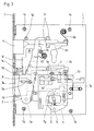
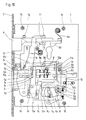
- Lock Intended for high security doors, especially in prisons Lock comprises a lock plate 1, at the front, angled edge of one Forend 2 is attached. Through an opening in the faceplate 2 protrudes at the front end a locking shaft 3 formed locking head 3a.
- the bolt shaft 3 is by means of elongated holes 3b slidably mounted on guide pins 1a, which on Lock plate 1 are attached. He is wearing a 3d tour pen.
- the lock plate 1 is still with Provide threaded bushings 1b. This situation is best seen in Fig. 11 too detect.
- a key S which is designed as a double-bit key.
- the Fig. 11 drawn bolt step of this key S acts on one Translation lever 4, the one on the lock plate 1 bearing mandrel 1c is pivotally mounted and in a recess in the locking shaft 3 intervenes.
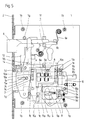
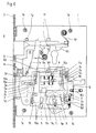
- the bolt thereby reaches the one in FIG. 3 drawn position, in which the front edge of the bolt head 3a behind the The rear edge of the faceplate 2 is. To have adequate leadership in this position ensure the bolt, 1 guide pieces 1d are on the lock plate attached, which cooperate with the bolt head 3a.
- FIG Change 5 This additional retraction of the bolt takes place according to FIG Change 5 to be able to operate a trap 6.
- the change 5 is again over a bearing mandrel 1e pivotally mounted on the lock plate 1. He owns one Guide slot 5a for a driving pin arranged on the locking shaft 3 3c.
- the guide slot 5a is formed such that the driving pin 3c is at a movement of the locking shaft 3 between those in FIGS. 1 and 2 positions shown can move freely in the guide slot 5a, however the change 5 is pivoted clockwise when the Bolt shaft 3 from the position shown in FIG. 2 to that shown in FIG. 3 Position is retracted further into the lock housing.
- the upper end of the change 5 pulls the trap 6 against By force of a latch spring 6a back into the lock.
- Fig. 11 reveals, the shaft of the trap 6 by guide pieces 1f and one Guide pin 1g, which in turn are attached to the lock plate 1, in the longitudinal direction flexibly guided.
- the trap 6 can also regardless of the operation of the Change 5 through a profile cylinder against the force of the latch spring 6a be withdrawn.
- This profile cylinder is in the drawings, in particular 11 only hinted at. His locking nose, not shown, works with one Projection 6b of the trap 6 together.
- both the actuation of the latch 3 and the retraction of the latch 6 are secured by at least one tumbler block, the at least one convertible, consisting of a locking tumbler and a locking tumbler Guard locking and other, not convertible tumblers includes.
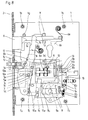
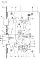
- 12 is one of the tumblers 7 which cannot be changed, in addition to those shown in Fig. 11 shown parts of the castle. The function of this non-convertible Tumblers 7 is shown in FIGS. 1 to 3.
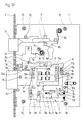
- a switchable lock consisting of 8 and locking 9 Guard locking is shown in FIG. 13 with regard to its structure and with regard to its function 4 to 10.
- Fig. 12 it can be seen that the fixed, i.e. not changeable tumbler 7 with Guide slots 7a is provided, in each of which a rectangular guide mandrel 1h engages, which in turn is attached to the lock plate 1. That way tumbler 7 mounted on the lock plate 1 in a stationary manner can thus be in a vertical position Direction to be moved. This movement takes place through to the respective Tumbler 7 belonging to the level of the key bit as a double bit key trained key S.
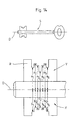
- FIG. 14 shows the view of a key S and the enlarged representation of its double beard consisting of front beard V and rear beard H as well as its axis of rotation D.
- the distances a 1 to a 6 of the front beard steps and the distances b 1 to b 6 of the rear beard steps from the axis of rotation D are different for each non-adjustable tumbler 7, as can be seen from the enlarged view.
- the sum of the distances a 1 plus b 1 , a 2 plus b 2 etc. is the same for all the tumblers 7 that cannot be changed, so that for the tumblers 7 that cannot be changed, the dimensions of the closing channels 7b are identical, their position within the tumbler 7 however is different. This also results in different configurations for the tour pin channel 7c in the case of the individual tumblers 7 that cannot be changed.
- Existing tumbler set includes, in addition to the fixed, i.e. not changeable tumblers 7 at least one more, from a Locking tumbler 8 and a locking tumbler 9 existing tumbler. This Configurable guard locking and the parts required for its conversion are shown in Fig. 13 shown.
- the or each switchable tumbler consists of a blocking tumbler 8 with a tour pin channel 8a and a locking tumbler 9, which consists of two parts consists, namely the upper part 9o and the lower part 9u.
- Upper part 9o and lower part 9u of the locking tumbler 9 together form the closing channel 9a, depending on Training of the associated key bit level is adjustable.
- the upper part 9o of the locking tumbler 9 by means of two in Elongated holes 9b engaging guide pins 1k movable in height on the Lock plate 1 out, whereas the lower part 9u of the locking tumbler 9 and Locking tumbler 8 are guided in a vertically movable manner on guide mandrels 10a a changeover plate 10 are arranged.
- the lower part 9u of the locking tumbler 9 is for this purpose in the illustrated embodiment with three elongated holes 9c trained for the guide mandrels 10a.
- the locking tumbler 8 has Embodiment only one slot 8b for a guide mandrel 10a, because the Locking tumbler 8 also with its front on the lower part 9u Locking tumbler 9 is guided, as can best be seen from FIG. 13.
- Both between the lower part 9u and the upper part 9o of the locking tumbler 9 also between the upper part 9o of the locking tumbler 9 and the locking tumbler 8 clutch gears 11a and 11b are formed, so that on the one hand Upper part 9o and lower part 9u of the locking tumbler 9 relative to one another and on the other hand, the locking tumbler 8 relative to the upper part 9o of the closing tumbler 9 can be set in different positions.
- the changeover slide 12 has a control slot 12a into which a mandrel 10c arranged on the changeover plate 10 intervenes. If the changeover slide 12 by means of a key operated Conversion eccentric 14 raised against the force of the clutch spring 13, causes that consisting of the mandrel 10c and the control slot 12a Slot control a movement of the changeover plate 10 against the force of it Tension spring 10b in Fig. 13 to the left by an amount such that the Clutch teeth 11a and 11b disengage. In this decoupled position can both the relative position between the lower part 9u and Upper part 9o of the locking tumbler 9 and the relative position of the upper part 9o the locking tumbler 9 can be changed to the locking tumbler 8. Once the Switching eccentric 14 is rotated back into its original position, the Changeover slide 12 due to the clutch spring 13 and the changeover plate 10 due to its tension spring 10b again in that shown in Fig. 13 Clutch position.
- this key S 1 is now inserted according to FIG. 9 and turned into the position shown in FIG. 9.
- this new key S 1 transfers the upper part 9o and lower part 9u of the locking tumbler 9 to a new relative position in which the locking channel 9a of the locking tumbler 9 receives its new design.
- the changeover key U and with it the changeover eccentric 14 is now turned back into its initial position, the changeover slide 12 is lowered due to the clutch spring 13 loading it and thus a return of the changeover plate 10 due to the tension spring 10b to the initial position in which the two clutch teeth 11a and 11b interlock in the new mapping. This completes the changeover of the three-part tumbler consisting of locking tumbler 8 and upper part 9o and lower part 9u of the closing tumbler 9.
- FIG. 14 shows that the distance c 1 of the front beard V is identical to the distance c 2 of the rear beard H from the axis of rotation D of the key S in the key step intended for the changeable guard locking.
- the step jump to the adjacent steps for the tumblers 7 that cannot be changed is however twice as large as the step jumps between neighboring steps of these tumblers 7.
- the bolt step R of the key S is identified in FIG. 14.
Landscapes
- Train Traffic Observation, Control, And Security (AREA)
- Lock And Its Accessories (AREA)
Applications Claiming Priority (2)
| Application Number | Priority Date | Filing Date | Title |
|---|---|---|---|
| DE19826869 | 1998-06-17 | ||
| DE1998126869 DE19826869C1 (de) | 1998-06-17 | 1998-06-17 | Schloß für Hochsicherheitstüren |
Publications (1)
| Publication Number | Publication Date |
|---|---|
| EP0976894A2 true EP0976894A2 (fr) | 2000-02-02 |
Family
ID=7871091
Family Applications (1)
| Application Number | Title | Priority Date | Filing Date |
|---|---|---|---|
| EP19990110847 Withdrawn EP0976894A2 (fr) | 1998-06-17 | 1999-06-07 | Serrure pour portes haute sécuritées |
Country Status (2)
| Country | Link |
|---|---|
| EP (1) | EP0976894A2 (fr) |
| DE (1) | DE19826869C1 (fr) |
Cited By (1)
| Publication number | Priority date | Publication date | Assignee | Title |
|---|---|---|---|---|
| GB2466962A (en) * | 2009-01-15 | 2010-07-21 | Securistyle Ltd | A locking mechanism with various control arrangements |
Families Citing this family (6)
| Publication number | Priority date | Publication date | Assignee | Title |
|---|---|---|---|---|
| EP1347130A1 (fr) * | 2002-03-22 | 2003-09-24 | Steinbach & Vollmann GmbH & Co. | Serrure pour portes de sécurité |
| DE102006060448A1 (de) | 2006-12-19 | 2008-06-26 | Dorma Gmbh + Co. Kg | Selbstverriegelndes Panikschloss |
| DE102006060449A1 (de) | 2006-12-19 | 2008-06-26 | Dorma Gmbh + Co. Kg | Selbstverriegelndes Panikschloss |
| DE102006060451A1 (de) | 2006-12-19 | 2008-06-26 | Dorma Gmbh + Co. Kg | Selbstverriegelndes Panikschloss, sowie ein Verfahren zum Betrieb eines selbstverriegelnden Panikschlosses |
| DE102006060450A1 (de) | 2006-12-19 | 2008-06-26 | Dorma Gmbh + Co. Kg | Selbstverriegelndes, elektromechanisches Panikschloss |
| EP2304136B1 (fr) * | 2008-05-06 | 2013-06-26 | CISA S.p.A. | Verrou antieffraction |
Family Cites Families (3)
| Publication number | Priority date | Publication date | Assignee | Title |
|---|---|---|---|---|
| DE4431923C1 (de) * | 1994-09-08 | 1995-10-26 | Steinbach & Vollmann | Schloß für Gefängnistüren |
| IT1279602B1 (it) * | 1995-05-26 | 1997-12-16 | Italiana Serrature Affini | Perfezionamenti ad una serratura con nottolini a piastre e cifratura cambiabile |
| DE19738244C2 (de) * | 1997-09-02 | 2002-04-11 | Steinbach & Vollmann | Schloß für Sicherheitstüren |
-
1998
- 1998-06-17 DE DE1998126869 patent/DE19826869C1/de not_active Expired - Fee Related
-
1999
- 1999-06-07 EP EP19990110847 patent/EP0976894A2/fr not_active Withdrawn
Cited By (1)
| Publication number | Priority date | Publication date | Assignee | Title |
|---|---|---|---|---|
| GB2466962A (en) * | 2009-01-15 | 2010-07-21 | Securistyle Ltd | A locking mechanism with various control arrangements |
Also Published As
| Publication number | Publication date |
|---|---|
| DE19826869C1 (de) | 2000-01-13 |
Similar Documents
| Publication | Publication Date | Title |
|---|---|---|
| EP0796968B1 (fr) | Dispositif de fermeture | |
| EP0854261A1 (fr) | Serrure autobloquante | |
| DE19626745C1 (de) | Selbstverriegelndes Panikschloß | |
| DE102004012108B4 (de) | Treibstangenschloss für Türen, Fenster oder dergleichen mit Panikfunktion und Mehrpunktverriegelung | |
| DE29608862U1 (de) | Schloß, insbesondere Einsteckschloß | |
| EP0425431B1 (fr) | Serrure | |
| DE3425565A1 (de) | Treibstangenschloss | |
| EP0092630B1 (fr) | Engrenage de serrure pour battant de porte | |
| EP2206858B1 (fr) | Verrou de porte | |
| EP0653535B1 (fr) | Serrure | |
| DE19826869C1 (de) | Schloß für Hochsicherheitstüren | |
| EP0471976B1 (fr) | Crémone | |
| DE3940393C2 (de) | Sicherheitsschloß | |
| EP0885340B1 (fr) | Dispositif de verrouillage pour un vantail, en particulier pour une porte comprenant une pluralite de verrous | |
| EP0298292B1 (fr) | Serrure de porte à pêne et demi-tour coulissants | |
| DE4431925C2 (de) | Schloß für Gefängnistüren | |
| DE19738244C2 (de) | Schloß für Sicherheitstüren | |
| EP1156180B1 (fr) | Serrure avec une course de pêne étendue et avec une fonction anti-panique | |
| EP0913550B2 (fr) | Crémone-serrure | |
| CH671427A5 (en) | Door or window lock - locks catch also when bolt is locked | |
| DE3042611C2 (fr) | ||
| DE3513265C2 (de) | Schloß für Justizvollzugsanstalten | |
| DE4431923C1 (de) | Schloß für Gefängnistüren | |
| DE1919347A1 (de) | Automatische Verriegelung | |
| EP0701034B1 (fr) | Serrure pour porte de prison |
Legal Events
| Date | Code | Title | Description |
|---|---|---|---|
| PUAI | Public reference made under article 153(3) epc to a published international application that has entered the european phase |
Free format text: ORIGINAL CODE: 0009012 |
|
| AK | Designated contracting states |
Kind code of ref document: A2 Designated state(s): AT BE CH CY DE DK ES FI FR GB GR IE IT LI LU MC NL PT SE |
|
| AX | Request for extension of the european patent |
Free format text: AL;LT;LV;MK;RO;SI |
|
| STAA | Information on the status of an ep patent application or granted ep patent |
Free format text: STATUS: THE APPLICATION IS DEEMED TO BE WITHDRAWN |
|
| 18D | Application deemed to be withdrawn |
Effective date: 20030103 |