EP0976894A2 - Lock for highly safe doors - Google Patents
Lock for highly safe doors Download PDFInfo
- Publication number
- EP0976894A2 EP0976894A2 EP19990110847 EP99110847A EP0976894A2 EP 0976894 A2 EP0976894 A2 EP 0976894A2 EP 19990110847 EP19990110847 EP 19990110847 EP 99110847 A EP99110847 A EP 99110847A EP 0976894 A2 EP0976894 A2 EP 0976894A2
- Authority
- EP
- European Patent Office
- Prior art keywords
- locking
- tumbler
- lock
- key
- tumblers
- Prior art date
- Legal status (The legal status is an assumption and is not a legal conclusion. Google has not performed a legal analysis and makes no representation as to the accuracy of the status listed.)
- Withdrawn
Links
- 230000008878 coupling Effects 0.000 claims abstract description 12
- 238000010168 coupling process Methods 0.000 claims abstract description 12
- 238000005859 coupling reaction Methods 0.000 claims abstract description 12
- 230000002441 reversible effect Effects 0.000 abstract 1
- 108010063955 thrombin receptor peptide (42-47) Proteins 0.000 description 8
- 238000006243 chemical reaction Methods 0.000 description 5
- 230000000903 blocking effect Effects 0.000 description 4
- 238000013519 translation Methods 0.000 description 2
- 238000013461 design Methods 0.000 description 1
- 238000003780 insertion Methods 0.000 description 1
- 230000037431 insertion Effects 0.000 description 1
- 238000013507 mapping Methods 0.000 description 1
- 239000007787 solid Substances 0.000 description 1
- 238000012549 training Methods 0.000 description 1
Images


Classifications
-
- E—FIXED CONSTRUCTIONS
- E05—LOCKS; KEYS; WINDOW OR DOOR FITTINGS; SAFES
- E05B—LOCKS; ACCESSORIES THEREFOR; HANDCUFFS
- E05B21/00—Locks with lamelliform tumblers which are not set by the insertion of the key and in which the tumblers do not follow the movement of the bolt e.g. Chubb-locks
-
- E—FIXED CONSTRUCTIONS
- E05—LOCKS; KEYS; WINDOW OR DOOR FITTINGS; SAFES
- E05B—LOCKS; ACCESSORIES THEREFOR; HANDCUFFS
- E05B35/00—Locks for use with special keys or a plurality of keys ; keys therefor
- E05B35/08—Locks for use with special keys or a plurality of keys ; keys therefor operable by a plurality of keys
- E05B35/083—Locks for use with special keys or a plurality of keys ; keys therefor operable by a plurality of keys with changeable combination
-
- E—FIXED CONSTRUCTIONS
- E05—LOCKS; KEYS; WINDOW OR DOOR FITTINGS; SAFES
- E05B—LOCKS; ACCESSORIES THEREFOR; HANDCUFFS
- E05B59/00—Locks with latches separate from the lock-bolts or with a plurality of latches or lock-bolts
-
- E—FIXED CONSTRUCTIONS
- E05—LOCKS; KEYS; WINDOW OR DOOR FITTINGS; SAFES
- E05B—LOCKS; ACCESSORIES THEREFOR; HANDCUFFS
- E05B65/00—Locks or fastenings for special use
- E05B65/0017—Jail locks
Definitions
- the invention relates to a lock for high security doors with at least one Guard locking set, the at least one, from a locking lock and one Closing tumbler includes existing, switchable tumbler, the blocking tumbler and the locking tumbler by one for a change of the closing releasable coupling are connected to each other, and with a through the Locked change for the actuation of a trap by a Double bit key with different beards.
- the invention has for its object to provide a lock of the type described above, from the tumblers at least one tumbler can be switched and the overall purpose of avoiding tumbler springs a closed locking channel with a predetermined distance according to the respective key bit level between the upper and lower part of the locking channel have, which should take place via a change secured by the tumblers without changing the double-bit key.
- the solution to this problem by the invention is characterized in that the locking tumbler is formed in two parts from an upper part containing the upper part of the closing channel and a lower part containing the lower part of the closing channel, one of which can be detachably coupled to the associated blocking tumbler via the coupling and which can also be coupled to one another by a releasable coupling and are loaded relative to one another by a spring.
- the remaining, apart from the at least one changeable guard locking, Unlockable tumblers can use one-piece tumblers be predetermined locking channel, which at the same time the locking and the Form locking tumbler.
- the dimensions of the closing channel and that for the The blocking channel provided for the tour pin accordingly corresponds to the respective one Key bit level, which can be used with all, for the respective lock Keys is the same.
- the tumbler set thus includes tumblers with fixed predetermined locking channel.
- the step change is convertible two-part locking tumbler twice as large as the increment of the tumblers with a fixed locking channel, in order to change a to obtain a sufficiently large restricted area on the tumblers.
- the distance is Forebeard step and the rear beard step from the axis of rotation of the Double-bit key for the switchable locking device identical, whereas the Distances of the front beard step and the rear beard step from the axis of rotation of the Double bit key for the tumblers that cannot be changed are different and the sum of the distances of the forebeard and backbeard stages is not for all changeable tumblers is the same.
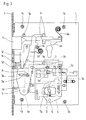
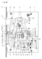
- Lock Intended for high security doors, especially in prisons Lock comprises a lock plate 1, at the front, angled edge of one Forend 2 is attached. Through an opening in the faceplate 2 protrudes at the front end a locking shaft 3 formed locking head 3a.
- the bolt shaft 3 is by means of elongated holes 3b slidably mounted on guide pins 1a, which on Lock plate 1 are attached. He is wearing a 3d tour pen.
- the lock plate 1 is still with Provide threaded bushings 1b. This situation is best seen in Fig. 11 too detect.
- a key S which is designed as a double-bit key.
- the Fig. 11 drawn bolt step of this key S acts on one Translation lever 4, the one on the lock plate 1 bearing mandrel 1c is pivotally mounted and in a recess in the locking shaft 3 intervenes.
- the bolt thereby reaches the one in FIG. 3 drawn position, in which the front edge of the bolt head 3a behind the The rear edge of the faceplate 2 is. To have adequate leadership in this position ensure the bolt, 1 guide pieces 1d are on the lock plate attached, which cooperate with the bolt head 3a.
- FIG Change 5 This additional retraction of the bolt takes place according to FIG Change 5 to be able to operate a trap 6.
- the change 5 is again over a bearing mandrel 1e pivotally mounted on the lock plate 1. He owns one Guide slot 5a for a driving pin arranged on the locking shaft 3 3c.
- the guide slot 5a is formed such that the driving pin 3c is at a movement of the locking shaft 3 between those in FIGS. 1 and 2 positions shown can move freely in the guide slot 5a, however the change 5 is pivoted clockwise when the Bolt shaft 3 from the position shown in FIG. 2 to that shown in FIG. 3 Position is retracted further into the lock housing.
- the upper end of the change 5 pulls the trap 6 against By force of a latch spring 6a back into the lock.
- Fig. 11 reveals, the shaft of the trap 6 by guide pieces 1f and one Guide pin 1g, which in turn are attached to the lock plate 1, in the longitudinal direction flexibly guided.
- the trap 6 can also regardless of the operation of the Change 5 through a profile cylinder against the force of the latch spring 6a be withdrawn.
- This profile cylinder is in the drawings, in particular 11 only hinted at. His locking nose, not shown, works with one Projection 6b of the trap 6 together.
- both the actuation of the latch 3 and the retraction of the latch 6 are secured by at least one tumbler block, the at least one convertible, consisting of a locking tumbler and a locking tumbler Guard locking and other, not convertible tumblers includes.
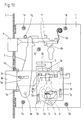
- 12 is one of the tumblers 7 which cannot be changed, in addition to those shown in Fig. 11 shown parts of the castle. The function of this non-convertible Tumblers 7 is shown in FIGS. 1 to 3.
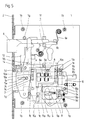
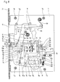
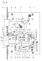
- a switchable lock consisting of 8 and locking 9 Guard locking is shown in FIG. 13 with regard to its structure and with regard to its function 4 to 10.
- Fig. 12 it can be seen that the fixed, i.e. not changeable tumbler 7 with Guide slots 7a is provided, in each of which a rectangular guide mandrel 1h engages, which in turn is attached to the lock plate 1. That way tumbler 7 mounted on the lock plate 1 in a stationary manner can thus be in a vertical position Direction to be moved. This movement takes place through to the respective Tumbler 7 belonging to the level of the key bit as a double bit key trained key S.
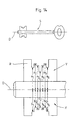
- FIG. 14 shows the view of a key S and the enlarged representation of its double beard consisting of front beard V and rear beard H as well as its axis of rotation D.
- the distances a 1 to a 6 of the front beard steps and the distances b 1 to b 6 of the rear beard steps from the axis of rotation D are different for each non-adjustable tumbler 7, as can be seen from the enlarged view.
- the sum of the distances a 1 plus b 1 , a 2 plus b 2 etc. is the same for all the tumblers 7 that cannot be changed, so that for the tumblers 7 that cannot be changed, the dimensions of the closing channels 7b are identical, their position within the tumbler 7 however is different. This also results in different configurations for the tour pin channel 7c in the case of the individual tumblers 7 that cannot be changed.
- Existing tumbler set includes, in addition to the fixed, i.e. not changeable tumblers 7 at least one more, from a Locking tumbler 8 and a locking tumbler 9 existing tumbler. This Configurable guard locking and the parts required for its conversion are shown in Fig. 13 shown.
- the or each switchable tumbler consists of a blocking tumbler 8 with a tour pin channel 8a and a locking tumbler 9, which consists of two parts consists, namely the upper part 9o and the lower part 9u.
- Upper part 9o and lower part 9u of the locking tumbler 9 together form the closing channel 9a, depending on Training of the associated key bit level is adjustable.
- the upper part 9o of the locking tumbler 9 by means of two in Elongated holes 9b engaging guide pins 1k movable in height on the Lock plate 1 out, whereas the lower part 9u of the locking tumbler 9 and Locking tumbler 8 are guided in a vertically movable manner on guide mandrels 10a a changeover plate 10 are arranged.
- the lower part 9u of the locking tumbler 9 is for this purpose in the illustrated embodiment with three elongated holes 9c trained for the guide mandrels 10a.
- the locking tumbler 8 has Embodiment only one slot 8b for a guide mandrel 10a, because the Locking tumbler 8 also with its front on the lower part 9u Locking tumbler 9 is guided, as can best be seen from FIG. 13.
- Both between the lower part 9u and the upper part 9o of the locking tumbler 9 also between the upper part 9o of the locking tumbler 9 and the locking tumbler 8 clutch gears 11a and 11b are formed, so that on the one hand Upper part 9o and lower part 9u of the locking tumbler 9 relative to one another and on the other hand, the locking tumbler 8 relative to the upper part 9o of the closing tumbler 9 can be set in different positions.
- the changeover slide 12 has a control slot 12a into which a mandrel 10c arranged on the changeover plate 10 intervenes. If the changeover slide 12 by means of a key operated Conversion eccentric 14 raised against the force of the clutch spring 13, causes that consisting of the mandrel 10c and the control slot 12a Slot control a movement of the changeover plate 10 against the force of it Tension spring 10b in Fig. 13 to the left by an amount such that the Clutch teeth 11a and 11b disengage. In this decoupled position can both the relative position between the lower part 9u and Upper part 9o of the locking tumbler 9 and the relative position of the upper part 9o the locking tumbler 9 can be changed to the locking tumbler 8. Once the Switching eccentric 14 is rotated back into its original position, the Changeover slide 12 due to the clutch spring 13 and the changeover plate 10 due to its tension spring 10b again in that shown in Fig. 13 Clutch position.
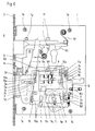
- this key S 1 is now inserted according to FIG. 9 and turned into the position shown in FIG. 9.
- this new key S 1 transfers the upper part 9o and lower part 9u of the locking tumbler 9 to a new relative position in which the locking channel 9a of the locking tumbler 9 receives its new design.
- the changeover key U and with it the changeover eccentric 14 is now turned back into its initial position, the changeover slide 12 is lowered due to the clutch spring 13 loading it and thus a return of the changeover plate 10 due to the tension spring 10b to the initial position in which the two clutch teeth 11a and 11b interlock in the new mapping. This completes the changeover of the three-part tumbler consisting of locking tumbler 8 and upper part 9o and lower part 9u of the closing tumbler 9.
- FIG. 14 shows that the distance c 1 of the front beard V is identical to the distance c 2 of the rear beard H from the axis of rotation D of the key S in the key step intended for the changeable guard locking.
- the step jump to the adjacent steps for the tumblers 7 that cannot be changed is however twice as large as the step jumps between neighboring steps of these tumblers 7.
- the bolt step R of the key S is identified in FIG. 14.
Landscapes
- Train Traffic Observation, Control, And Security (AREA)
- Lock And Its Accessories (AREA)
Abstract
Die Erfindung betrifft ein Schloß für Hochsicherheitstüren mit mindestens einem Zuhaltungssatz, der mindestens eine, aus einer Sperrzuhaltung (8) und einer Schließzuhaltung (9) bestehende umstellbare Zuhaltung umfaßt, wobei die Sperrzuhaltung (8) und die Schließzuhaltung (9) durch eine für eine Umstellung der Schließzuhaltung lösbare Kupplung (11b) miteinander verbunden sind, und mit einem durch den Zuhaltungssatz gesicherten Wechsel (5) für die Betätigung einer Falle (6) durch einen Doppelbartschlüssel (S) mit unterschiedlichen Bärten. Um bei einem derartigen Schloß die Zuhaltungen zwecks Verzicht auf Zuhaltungsfedern mit geschlossenen Schließkanälen (7b, 9a) auszubilden und eine Fallenbetätigung ohne Umstecken des Doppelbartschlüssels (S) vornehmen zu können, ist die umstellbare Schließzuhaltung (9) zweiteilig aus einem den oberen Teil des Schließkanals (9a) enthaltenden Oberteil (9o) und einem den unteren Teil des Schließkanals (9a) enthaltenden Unterteil (9u) ausgebildet, von denen einer über die Kupplung (11b) lösbar mit der zugehörigen Sperrzuhaltung (8) kuppelbar ist und die miteinander ebenfalls durch eine lösbare Kupplung (11a) kuppelbar und relativ zueinander durch eine Feder (9d) belastet sind. <IMAGE>The invention relates to a lock for high-security doors with at least one tumbler set, which comprises at least one convertible tumbler consisting of a locking tumbler (8) and a locking tumbler (9), the locking tumbler (8) and the closing tumbler (9) being adapted for a changeover the locking tumbler releasable coupling (11b) are connected to each other, and with a change (5) secured by the tumbler set for the actuation of a latch (6) by a double-bit key (S) with different beards. In order to form the tumblers with such a lock in order to dispense with tumbler springs with closed locking channels (7b, 9a) and to be able to actuate the latch without changing the double-bit key (S), the reversible locking tumbler (9) consists of two parts from an upper part of the locking channel ( 9a) containing the upper part (9o) and a lower part (9u) containing the lower part of the closing channel (9a), one of which can be detachably coupled to the associated locking tumbler (8) via the coupling (11b) and which can also be coupled to one another by a releasable one Coupling (11a) can be coupled and is loaded relative to one another by a spring (9d). <IMAGE>
Description
Die Erfindung betrifft ein Schloß für Hochsicherheitstüren mit mindestens einem Zuhaltungssatz, der mindestens eine, aus einer Sperrzuhaltung und einer Schließzuhaltung bestehende, umstellbare Zuhaltung umfaßt, wobei die Sperrzuhaltung und die Schließzuhaltung durch eine für eine Umstellung der Schließung lösbare Kupplung miteinander verbunden sind, und mit einem durch den Zuhaltungssatz gesicherten Wechsel für die Betätigung einer Falle durch einen Doppelbartschlüssel mit unterschiedlichen Bärten.The invention relates to a lock for high security doors with at least one Guard locking set, the at least one, from a locking lock and one Closing tumbler includes existing, switchable tumbler, the blocking tumbler and the locking tumbler by one for a change of the closing releasable coupling are connected to each other, and with a through the Locked change for the actuation of a trap by a Double bit key with different beards.
Ein derartiges Schloß für Hochsicherheitstüren ist in der DE 197 38 244.4-15 offenbart. Um nach dem Zurückziehen des Riegels anschließend die Falle betätigen zu können, mußte bei diesem Schloß der Schlüssel aus dem Schloß herausgenommen und umgedreht in das Schloß eingeführt werden, da die für die Betätigung des Riegels verwendete Schlüsselbartstufe auch zur Betätigung der Falle benutzt wird. Diesen Handhabungsnachteil hat auch ein aus der DE 44 31 923 C1 bekanntes Schloß, bei dem die geteilten Zuhaltungen jeweils durch eine Feder belastet sind, welche einen erhöhten Verschleiß des Schlüsselbartes und der Schließkanäle der Zuhaltungen zur Folge haben und zu einem Ausfall des Schlosses führen, wenn eine der Federn bricht.Such a lock for high security doors is in DE 197 38 244.4-15 disclosed. To the trap after pulling back the latch To be able to operate, the key had to come out of the lock removed and inserted into the lock upside down, as for the Actuation of the latch also used the key bit level to actuate the Trap is used. This handling disadvantage also has one from DE 44 31 923 C1 well-known castle, in which the shared tumblers each by a Are spring loaded, which increases wear of the key bit and of the locking channels of the tumblers and a failure of the Lock if one of the springs breaks.
Der Erfindung liegt die Aufgabe zugrunde, ein Schloß der eingangs beschriebenen Art zu schaffen, von dessen Zuhaltungen zumindest eine Zuhaltung umstellbar ist und die insgesamt zwecks Vermeidung von Zuhaltungsfedern einen geschlossenen Schließkanal mit entsprechend der jeweiligen Schlüsselbartstufe vorgegebenem Abstand zwischen dem oberen und dem unteren Teil des Schließkanals haben, wobei die über einen durch die Zuhaltungen gesicherten Wechsel stattfindende Fallenbetätigung ohne Umstecken des Doppelbartschlüssels erfolgen soll.The invention has for its object to provide a lock of the type described above, from the tumblers at least one tumbler can be switched and the overall purpose of avoiding tumbler springs a closed locking channel with a predetermined distance according to the respective key bit level between the upper and lower part of the locking channel have, which should take place via a change secured by the tumblers without changing the double-bit key.
Die Lösung dieser Aufgabenstellung durch die Erfindung ist dadurch gekennzeichnet, daß die Schließzuhaltung zweiteilig aus einem den oberen Teil des Schließkanals enthaltenden Oberteil und einem den unteren Teil des Schließkanals enthaltenden Unterteil ausgebildet ist, von denen einer über die Kupplung lösbar mit der zugehörigen Sperrzuhaltung kuppelbar ist und die miteinander ebenfalls durch eine lösbare Kupplung kuppelbar und relativ zueinander durch eine Feder belastet sind.The solution to this problem by the invention is characterized in that the locking tumbler is formed in two parts from an upper part containing the upper part of the closing channel and a lower part containing the lower part of the closing channel, one of which can be detachably coupled to the associated blocking tumbler via the coupling and which can also be coupled to one another by a releasable coupling and are loaded relative to one another by a spring.
Mit der Erfindung wird ein zum Einsatz bei Hochsicherheitstüren bestimmtes Schloß geschaffen, das einerseits ohne federbelastete und damit einem erhöhten Verschleiß unterworfene Zuhaltungen auskommt und dessen über einen Wechsel erfolgende Fallenbetätigung andererseits trotz der Verwendung zumindest einer umstellbaren Zuhaltung ohne ein Herausnehmen und Umstecken des Schlüssels zwischen Riegel- und Fallenbetätigung erfolgt.With the invention is intended for use in high security doors Castle created, the one hand without spring-loaded and thus an elevated Guard locks subject to wear and a change trap actuation on the other hand despite the use of at least one Configurable guard locking without removing and changing the key between latch and latch actuation.
Die außer der zumindest einen umstellbaren Zuhaltung verwendeten restlichen, nicht umstellbaren Zuhaltungen können einteilige Zuhaltungen mit fest vorgegebenem Schließkanal sein, die zugleich die Sperrzuhaltung und die Schließzuhaltung bilden. Die Abmessungen des Schließkanals und des für den Tourstift vorgesehenen Sperrkanals entsprechen demgemäß der jeweiligen Schlüsselbartstufe, die bei sämtlichen, für das jeweilige Schloß verwendbaren Schlüsseln gleich ist. Außer der mindestens einen zweiteiligen Schließzuhaltung umfaßt der Zuhaltungssatz somit erfindungsgemäß Zuhaltungen mit fest vorgegebenem Schließkanal.The remaining, apart from the at least one changeable guard locking, Unlockable tumblers can use one-piece tumblers be predetermined locking channel, which at the same time the locking and the Form locking tumbler. The dimensions of the closing channel and that for the The blocking channel provided for the tour pin accordingly corresponds to the respective one Key bit level, which can be used with all, for the respective lock Keys is the same. Except for the at least one two-part locking tumbler According to the invention, the tumbler set thus includes tumblers with fixed predetermined locking channel.
Bei einer bevorzugten Ausführungsform der Erfindung ist der Stufensprung der umstellbaren zweiteiligen Schließzuhaltung doppelt so groß wie der Stufensprung der Zuhaltungen mit festem Schließkanal, um bei einer Umstellung eine ausreichend große Sperrfläche an den Zuhaltungen zu erhalten.In a preferred embodiment of the invention, the step change is convertible two-part locking tumbler twice as large as the increment of the tumblers with a fixed locking channel, in order to change a to obtain a sufficiently large restricted area on the tumblers.
Bei einer bevorzugten Ausführungsform der Erfindung sind der Abstand der Vorderbartstufe und der Hinterbartstufe von der Drehachse des Doppelbartschlüssels für die umstellbare Schließzuhaltung identisch, wogegen die Abstände der Vorderbartstufe und der Hinterbartstufe von der Drehachse des Doppelbartschlüssels für die nicht umstellbaren Zuhaltungen unterschiedlich sind und die Summe der Abstände von Vorderbart- und Hinterbartstufe für alle nicht umstellbaren Zuhaltungen gleich ist.In a preferred embodiment of the invention, the distance is Forebeard step and the rear beard step from the axis of rotation of the Double-bit key for the switchable locking device identical, whereas the Distances of the front beard step and the rear beard step from the axis of rotation of the Double bit key for the tumblers that cannot be changed are different and the sum of the distances of the forebeard and backbeard stages is not for all changeable tumblers is the same.
Auf der Zeichnung ist ein Ausführungsbeispiel des erfindungsgemäßen Schlosses dargestellt, und zwar zeigen:
- Fig. 1
- eine ohne Schloßdecke gezeichnete Draufsicht auf das Schloß mit Darstellung einer nicht umstellbaren einteiligen Zuhaltung bei ausgeschlossenem Riegel,
- Fig. 2
- eine der Fig. 1 entsprechende Darstellung bei zurückgezogenem Riegel,
- Fig. 3
- eine weitere Darstellung gemäß den Fig. 1 und 2 nach einer Fallenbetätigung,
- Fig. 4
- eine der Fig. 1 entsprechende Darstellung mit einer Draufsicht auf eine umstellbare Zuhaltung bei ausgeschlossenem Riegel,
- Fig. 5
- eine der Fig. 4 entsprechende Draufsicht bei zurückgezogenem Riegel,
- Fig. 6
- eine weitere Draufsicht gemäß den Fig. 4 und 5 bei zurückgezogener Falle,
- Fig. 7
- eine der Fig. 6 entsprechende Draufsicht nach einem Lösen der Kupplung zwischen Schließ- und Sperrzuhaltung mittels eines Umstellschlüssels,
- Fig. 8
- eine der Fig. 7 entsprechende Draufsicht nach Entfernen des bisher verwendeten Schlüssels,
- Fig. 9
- eine weitere Draufsicht gemäß den Fig. 7 und 8 nach Einführen eines neuen Schlüssels,
- Fig. 10
- eine der Fig. 7 entsprechende Draufsicht nach Umstellung der Schließzuhaltung auf den neuen Schlüssel,
- Fig. 11
- eine Draufsicht auf das Schloßblech mit Riegel, Wechsel und Falle,
- Fig. 12
- eine entsprechende Draufsicht auf das Schloßblech mit zusätzlicher Darstellung einer festen Zuhaltung,
- Fig. 13
- eine weitere Draufsicht auf das Schloßblech mit Darstellung einer umstellbaren Zuhaltung und
- Fig. 14
- eine Ansicht eines Doppelbartschlüssels und des Schlüsselbartes in vergrößerter Darstellung.
- Fig. 1
- a top view of the lock drawn without a lock cover, showing a non-convertible one-part tumbler with the bolt locked,
- Fig. 2
- 1 corresponding representation with the bolt withdrawn,
- Fig. 3
- 1 shows a further illustration according to FIGS. 1 and 2 after a latch actuation,
- Fig. 4
- 1 shows a representation corresponding to FIG. 1 with a plan view of a switchable tumbler with the bolt locked,
- Fig. 5
- 4 shows a top view corresponding to FIG. 4 with the bolt withdrawn,
- Fig. 6
- 4 shows a further top view according to FIGS. 4 and 5 with the trap withdrawn,
- Fig. 7
- 6 is a plan view corresponding to FIG. 6 after the clutch has been released between the locking and locking tumbler by means of a changeover key,
- Fig. 8
- 7 shows a top view corresponding to FIG. 7 after removal of the key previously used,
- Fig. 9
- 7 shows a further top view according to FIGS. 7 and 8 after insertion of a new key,
- Fig. 10
- 7 shows a top view corresponding to FIG. 7 after the locking tumbler has been changed over to the new key,
- Fig. 11
- a top view of the lock plate with bolt, change and latch,
- Fig. 12
- a corresponding top view of the lock plate with additional representation of a fixed tumbler,
- Fig. 13
- a further top view of the lock plate showing a switchable tumbler and
- Fig. 14
- a view of a double bit key and the key bit in an enlarged view.
Das für Hochsicherheitstüren insbesondere in Justizvollzugsanstalten bestimmte
Schloß umfaßt ein Schloßblech 1, an dessen vorderem, abgewinkelten Rand eine
Stulp 2 befestigt ist. Durch eine Öffnung in der Stulp 2 ragt der am vorderen Ende
eines Riegelschaftes 3 ausgebildete Riegelkopf 3a hindurch. Der Riegelschaft 3 ist
mittels Langlöchern 3b längsverschiebbar auf Führungsstiften 1a gelagert, die am
Schloßblech 1 befestigt sind. Er trägt einen Tourstift 3d. Zur Befestigung der auf
der Zeichnung nicht dargestellten Schloßdecke ist das Schloßblech 1 weiterhin mit
Gewindebüchsen 1b versehen. Diese Situation ist am besten in Fig. 11 zu
erkennen.Intended for high security doors, especially in prisons
Lock comprises a
Die Betätigung des aus Riegelschaft 3 und Riegelkopf 3a bestehenden Riegels
erfolgt durch einen Schlüssel S, der als Doppelbartschlüssel ausgebildet ist. Die in
Fig. 11 gezeichnete Riegelstufe dieses Schlüssels S wirkt auf einen
Übersetzungshebel 4, der um einen auf dem Schloßblech 1 befestigten Lagerdorn
1c verschwenkbar gelagert ist und in eine Aussparung des Riegelschaftes 3
eingreift. Hierdurch ist es möglich, den Riegel durch den Schlüssel S aus der in
Fig. 1 dargestellten ausgeschlossenen Stellung nicht nur in die Fig. 2 gezeichnete
eingezogene Stellung zurückzuziehen, sondern um einen weiteren Betrag in das
Schloß einzuziehen, und zwar mittels des Hinterbartes der Riegelstufe des
Schlüssels S, der demgemäß ohne Umstecken um einen Verdrehwinkel größer als
180° im Schloß gedreht wird. Der Riegel gelangt hierbei in die in Fig. 3
gezeichnete Stellung, in der die Vorderkante des Riegelkopfes 3a hinter der
Hinterkante der Stulp 2 liegt. Um in dieser Stellung eine ausreichende Führung
des Riegels sicherzustellen, sind auf dem Schloßblech 1 Führungsstücke 1d
befestigt, die mit dem Riegelkopf 3a zusammenwirken.The actuation of the bolt consisting of
Dieses zusätzliche Zurückziehen des Riegels erfolgt gemäß Fig. 3, um über einen
Wechsel 5 eine Falle 6 betätigen zu können. Der Wechsel 5 ist wiederum über
einen Lagerdorn 1e verschwenkbar am Schloßblech 1 gelagert. Er besitzt einen
Führungsschlitz 5a für einen auf dem Riegelschaft 3 angeordneten Mitnahmestift
3c. Der Führungsschlitz 5a ist derart ausgebildet, daß der Mitnahmestift 3c sich bei
einer Bewegung des Riegelschaftes 3 zwischen den in den Fig. 1 und 2
dargestellten Stellungen frei im Führungsschlitz 5a bewegen kann, daß jedoch
eine Verschwenkung des Wechsels 5 im Uhrzeigersinn erfolgt, wenn der
Riegelschaft 3 aus der in Fig. 2 gezeichneten Stellung in die in Fig. 3 gezeichnete
Stellung weiter in das Schloßgehäuse zurückgezogen wird.This additional retraction of the bolt takes place according to
In diesem Fall zieht das obere Ende des Wechsels 5 die Falle 6 entgegen der
Kraft einer Fallenfeder 6a in das Schloß zurück. Wie insbesondere Fig. 11
erkennen läßt, wird der Schaft der Falle 6 durch Führungsstücke 1f und einen
Führungsstift 1g, die wiederum am Schloßblech 1 befestigt sind, in Längsrichtung
beweglich geführt. Die Falle 6 kann außerdem unabhängig von der Betätigung des
Wechsels 5 durch einen Profilzylinder entgegen der Kraft der Fallenfeder 6a
zurückgezogen werden. Dieser Profilzylinder ist in den Zeichnungen, insbesondere
Fig. 11 lediglich angedeutet. Seine nicht dargestellte Schließnase wirkt mit einem
Vorsprung 6b der Falle 6 zusammen.In this case, the upper end of the
Sowohl das Betätigen des Riegels 3 als auch das Zurückziehen der Falle 6 sind
durch mindestens einen Zuhaltungssatz gesichert, der mindestens eine
umstellbare, aus einer Sperrzuhaltung und einer Schließzuhaltung bestehende
Zuhaltung und weitere, nicht umstellbare Zuhaltungen umfaßt. In Fig. 12 ist eine
der nicht umstellbaren Zuhaltungen 7 gezeichnet, und zwar zusätzlich zu den in
Fig. 11 dargestellten Teilen des Schlosses. Die Funktion dieser nicht umstellbaren
Zuhaltungen 7 ist in den Fig. 1 bis 3 dargestellt.Both the actuation of the
Eine umstellbare, aus Sperrzuhaltung 8 und Schließzuhaltung 9 bestehende
Zuhaltung zeigt bezüglich ihres Aufbaus die Fig. 13 und bezüglich ihrer Funktion
die Fig. 4 bis 10. A switchable lock consisting of 8 and locking 9
Guard locking is shown in FIG. 13 with regard to its structure and with regard to its
In Fig. 12 ist erkennbar, daß die feste, d.h. nicht umstellbare Zuhaltung 7 mit
Führungsschlitzen 7a versehen ist, in die jeweils ein rechteckiger Führungsdorn 1h
eingreift, der wiederum auf dem Schloßblech 1 befestigt ist. Die auf diese Weise
ortsfest auf dem Schloßblech 1 gelagerte Zuhaltung 7 kann somit in senkrechter
Richtung bewegt werden. Diese Bewegung erfolgt durch die zur jeweiligen
Zuhaltung 7 gehörende Stufe des Schlüsselbartes des als Doppelbartschlüssel
ausgebildeten Schlüssels S.In Fig. 12 it can be seen that the fixed, i.e. not
Die Fig. 14 zeigt die Ansicht eines Schlüssels S sowie die vergrößerte Darstellung
seines aus Vorderbart V und Hinterbart H bestehenden Doppelbartes sowie seine
Drehachse D. Die Abstände a1 bis a6 der Vorderbartstufen und die Abstände b1
bis b6 der Hinterbartstufen von der Drehachse D sind hierbei für jede nicht
einstellbare Zuhaltung 7 unterschiedlich, wie sich aus der vergrößerten Darstellung
ergibt. Die Summe der Abstände a1 plus b1, a2 plus b2 usw. ist jedoch für alle
nicht umstellbaren Zuhaltungen 7 gleich, so daß sich für die nicht umstellbaren
Zuhaltungen 7 in den Abmessungen identische Schließkanäle 7b ergeben, deren
Lage innerhalb der Zuhaltung 7 jedoch unterschiedlich ist. Hierdurch ergeben sich
auch unterschiedliche Ausgestaltungen für den Tourstiftkanal 7c bei den
einzelnen, nicht umstellbaren Zuhaltungen 7.14 shows the view of a key S and the enlarged representation of its double beard consisting of front beard V and rear beard H as well as its axis of rotation D. The distances a 1 to a 6 of the front beard steps and the distances b 1 to b 6 of the rear beard steps from the axis of rotation D are different for each
Um den Riegelkopf 3a aus der in Fig. 1 dargestellten, ausgeschlossenen Stellung
zurückziehen zu können, müssen die festen Zuhaltungen 7 mittels der jeweils
passenden Schlüsselbartstufe durch den Vorderbart V des Doppelbartschlüssels S
derart angehoben werden, daß der Tourstift 3d in den Bereich des waagerechten
Teils des Tourstiftkanals 7c gelangt. Nur wenn dies bei allen nicht umstellbaren
Zuhaltungen 7 der Fall ist, kann durch weiteres Drehen des Schlüssels S der
Riegel aus seiner ausgeschlossenen Stellung gemäß Fig. 1 in die Stellung gemäß
Fig. 2 zurückgezogen werden, wobei der Tourstift 3d den vorderen waagerechten
Teil des Tourstiftkanals 7c passiert. Beim anschließenden Absenken der
Zuhaltungen 7 gelangt der Tourstift 3d in die in Fig. 2 erkennbare Stellung. Wenn
nunmehr über den durch den Zuhaltungssatz gesicherten Wechsel 5 die Falle 6
mittels des Hinterbartes H des Schlüssels S entgegen der Kraft der Fallenfeder 6a
aus der in Fig. 2 dargestellten vorderen Stellung in die in Fig. 3 gezeichnete
hintere Stellung zurückgezogen werden soll, müssen die nicht umstellbaren
Zuhaltungen 7 mittels der passenden Hinterbartstufen des Schlüssels S erneut so
weit angehoben werden, daß der Tourstift 3d in den waagerechten hinteren Teil
des Tourstiftkanals 7c eintreten kann. Nur wenn dies der Fall ist, kann der
Riegelschaft 3 aus der in Fig. 2 gezeichneten Stellung in die in Fig. 3 gezeichnete
Stellung bewegt werden, wobei über den Wechsel 5 die Falle 6 zurückgezogen
wird. Bei einem Zurückdrehen des Schlüssels S gelangt der Tourstift 3d wieder in
die in Fig. 2 gezeichnete Stellung innerhalb des Tourstiftkanals 7c. Der Riegel wird
in seine in Fig. 2 gezeichnete mittlere Stellung zurückbewegt. Die Fallenfeder 6a
schiebt die Falle 6 wiederum aus der Stulp 2 heraus in die in Fig. 2 gezeichnete
Lage.Around the
Der zur Sicherung der Betätigung sowohl des Riegels als auch der Falle 6
vorhandene Zuhaltungssatz umfaßt außer den voranstehend erläuterten festen,
d.h. nicht umstellbaren Zuhaltungen 7 mindestens eine weitere, aus einer
Sperrzuhaltung 8 und einer Schließzuhaltung 9 bestehende Zuhaltung. Diese
umstellbare Zuhaltung und die zu ihrer Umstellung benötigten Teile sind in Fig. 13
dargestellt.To secure the actuation of both the bolt and the
Hiernach besteht die bzw. jede umstellbare Zuhaltung aus einer Sperrzuhaltung 8
mit einem Tourstiftkanal 8a und einer Schließzuhaltung 9, die aus zwei Teilen
besteht, nämlich dem Oberteil 9o und dem Unterteil 9u. Oberteil 9o und Unterteil
9u der Schließzuhaltung 9 bilden gemeinsam den Schließkanal 9a, der je nach
Ausbildung der zugehörigen Schlüsselbartstufe verstellbar ist.According to this, the or each switchable tumbler consists of a blocking
Zu diesem Zweck ist das Oberteil 9o der Schließzuhaltung 9 mittels zweier in
Langlöcher 9b eingreifender Führungsdorne 1k in der Höhe beweglich auf dem
Schloßblech 1 geführt, wogegen das Unterteil 9u der Schließzuhaltung 9 und die
Sperrzuhaltung 8 höhenbeweglich auf Führungsdornen 10a geführt sind, die auf
einer Umstellplatte 10 angeordnet sind. Das Unterteil 9u der Schließzuhaltung 9 ist
zu diesem Zweck beim dargestellten Ausführungsbeispiel mit drei Langlöchern 9c
für die Führungsdorne 10a ausgebildet. Die Sperrzuhaltung 8 besitzt beim
Ausführungsbeispiel nur ein Langloch 8b für einen Führungsdorn 10a, da die
Sperrzuhaltung 8 darüber hinaus mit ihrer Vorderseite am Unterteil 9u der
Schließzuhaltung 9 geführt ist, wie am besten aus Fig. 13 hervorgeht.For this purpose, the upper part 9o of the locking
Sowohl zwischen dem Unterteil 9u und dem Oberteil 9o der Schließzuhaltung 9 als
auch zwischen dem Oberteil 9o der Schließzuhaltung 9 und der Sperrzuhaltung 8
sind Kupplungsverzahnungen 11a bzw. 11b ausgebildet, so daß einerseits
Oberteil 9o und Unterteil 9u der Schließzuhaltung 9 relativ zueinander und
andererseits die Sperrzuhaltung 8 relativ zum Oberteil 9o der Schließzuhaltung 9
in unterschiedlichen Stellungen festgelegt werden können.Both between the
Das Entkuppeln und Kuppeln dieser Teile miteinander geschieht mit Hilfe der
Umstellplatte 10, die in Fig. 13 in ihrer Kupplungsstellung dargestellt ist. Sie ist in
Richtung dieser Kupplungsstellung durch eine Zugfeder 10b belastet. Sie kann
jedoch entgegen der Kraft dieser Zugfeder 10b auf am Schloßblech 1 befestigten
Führungsdornen 1l bei der Darstellung in Fig. 13 so weit nach links verschoben
werden, daß die Kupplungsverzahnungen 11a und 11b außer Eingriff gelangen.
Diese Verlagerung der Umstellplatte 10 aus ihrer in Fig. 13 dargestellten
Kupplungsstellung in die in den Fig. 7 bis 9 dargestellte Freigabestellung geschieht
mittels eines Umstellschiebers 12. Dieser Umstellschieber 12 ist auf dem
Schloßblech 1 durch in Langlöcher eingreifende Führungsbolzen höhenbeweglich
geführt und durch eine Kupplungsfeder 13 belastet. Der Umstellschieber 12 besitzt
einen Steuerschlitz 12a, in den ein auf der Umstellplatte 10 angeordneter Dorn 10c
eingreift. Wird der Umstellschieber 12 mittels eines schlüsselbetätigten
Umstellexzenters 14 entgegen der Kraft der Kupplungsfeder 13 angehoben,
bewirkt die aus dem Dorn 10c und dem Steuerschlitz 12a bestehende
Schlitzsteuerung eine Bewegung der Umstellplatte 10 entgegen der Kraft ihrer
Zugfeder 10b in Fig. 13 nach links, und zwar um einen derartigen Betrag, daß die
Kupplungsverzahnungen 11a und 11b außer Eingriff gelangen. In dieser
entkuppelten Stellung kann sowohl die Relativstellung zwischen Unterteil 9u und
Oberteil 9o der Schließzuhaltung 9 als auch die Relativstellung des Oberteils 9o
der Schließzuhaltung 9 zur Sperrzuhaltung 8 verändert werden. Sobald der
Umstellexzenter 14 in seine Ausgangslage zurückgedreht wird, gelangt der
Umstellschieber 12 aufgrund der Kupplungsfeder 13 und die Umstellplatte 10
aufgrund ihrer Zugfeder 10b wieder in die in Fig. 13 dargestellte
Kupplungsstellung.The uncoupling and coupling of these parts is done with the help of
Nach der Erläuterung des Aufbaus der umstellbaren Zuhaltung soll nunmehr deren Funktion anhand der Fig. 4 bis 10 erläutert werden. Hierbei zeigen die Fig. 4 bis 6 die Betätigung der umstellbaren Zuhaltung und die Fig. 7 bis 10 deren Umstellung auf einen Doppelbartschlüssel mit einem anderen Schlüsselbart. After the explanation of the structure of the changeable guard locking is now to be Function will be explained with reference to FIGS. 4 to 10. 4 to 6 the actuation of the switchable tumbler and FIGS. 7 to 10 the changeover on a double bit key with another key bit.
Entsprechend den Fig. 1 bis 3 bezüglich der festen Zuhaltung 7 erfolgt auch bei
der umstellbaren Zuhaltung gemäß den Fig. 4 bis 6 ein Zurückziehen des in der
ausgeschlossenen Stellung befindlichen Riegelkopfes 3a aus der Stellung nach
Fig. 4 in die Stellung nach Fig. 5 durch Drehen des Schlüssels S, dessen
Vorderbart V gemäß Fig. 4 die Schließzuhaltung 9 und mit dieser die
Sperrzuhaltung 8 anhebt, so daß der Tourstift 3d in den vorderen Teil des
waagerechten Tourstiftkanals 8a eintritt und der Riegel aus seiner
ausgeschlossenen Stellung nach Fig. 4 in seine zurückgezogene Stellung nach
Fig. 5 bewegt werden kann. In dieser Stellung befindet sich der Tourstift 3d im
hinteren Bereich des Tourstiftkanals 8a; er gelangt nach Absenken der
umstellbaren, aus Sperrzuhaltung 8 und Schließzuhaltung 9 bestehenden
Zuhaltung in die in Fig. 5 dargestellte Lage. Um ausgehend von der Stellung nach
Fig. 5 durch weiteres Zurückziehen des Riegels die Falle 6 über den Wechsel 5
betätigen zu können, muß die umstellbare Zuhaltung nunmehr mit Hilfe des
Hinterbarts H erneut gezielt angehoben werden, so daß der Tourstift 3d wiederum
in den waagerechten, und zwar diesmal hinteren Teil des Tourstiftkanals 8a
gelangt, wie dies die Fig. 6 zeigt. Nur in dieser durch den Zuhaltungssatz
überwachten Stellung der umstellbaren Zuhaltung kann die Falle 6 über den
Wechsel 5 betätigt werden.1 to 3 with respect to the fixed
Um die umstellbare Zuhaltung auf einen anderen Doppelbartschlüssel
umzustellen, ist es gemäß Fig. 7 erforderlich, mit Hilfe eines Umstellschlüssels U
bei geöffneter Tür die Kupplungsverzahnungen 11a und 11b zu entkuppeln. Durch
Drehen dieses Umstellschlüssels U wird über den Umstellexzenter 14 der
Umstellschieber 12 angehoben und die Umstellplatte 10 in der Zeichnung nach
links verschoben. Hierdurch erfolgt sowohl ein Entkuppeln des Unterteils 9u der
Schließzuhaltung 9 von ihrem Oberteil 9o als auch ein Entkuppeln der
Sperrzuhaltung 8 vom Oberteil 9o der Schließzuhaltung 9. Der alte Schlüssel
verbleibt hierbei gemäß Fig. 7 in der dort gezeichneten Lage, in der er Oberteil 9o
und Unterteil 9u der Schließzuhaltung 9 entgegen der Kraft einer Rückführfeder 9d
auseinanderhält.To switch the guard locking to another double-bit key
7, it is necessary, using a changeover key U
to disengage the
Wird nunmehr der Doppelbartschlüssel S in die in Fig. 8 dargestellte Lage gedreht,
zieht die Rückführfeder 9d Oberteil 9o und Unterteil 9u der Schließzuhaltung 9 bis
zur gegenseitigen Anlage zusammen. Diese Situation ist in Fig. 8 dargestellt. If the double-bit key S is now turned into the position shown in FIG. 8,
pulls the
Um die Schließzuhaltung 9 auf einen neuen Schlüssel S1 einzustellen, wird dieser
Schlüssel S1 nunmehr gemäß Fig. 9 eingeführt und in die in Fig. 9 dargestellte
Lage verdreht. Bei gelösten Kupplungsverzahnungen 11a und 11b überführt
dieser neue Schlüssel S1 Oberteil 9o und Unterteil 9u der Schließzuhaltung 9 in
eine neue Relativstellung zueinander, in der der Schließkanal 9a der
Schließzuhaltung 9 seine neue Gestaltung erhält. Wenn nunmehr der
Umstellschlüssel U und mit ihm der Umstellexzenter 14 in seine Ausgangslage
zurückgedreht wird, erfolgt ein Absenken des Umstellschiebers 12 aufgrund der
diesen belastenden Kupplungsfeder 13 und damit eine Rückkehr der Umstellplatte
10 aufgrund der Zugfeder 10b in die Ausgangslage, in der die beiden
Kupplungsverzahnungen 11a und 11b in der neuen Zuordnung ineinandergreifen.
Damit ist die Umstellung der dreiteiligen, aus Sperrzuhaltung 8 sowie Oberteil 9o
und Unterteil 9u der Schließzuhaltung 9 bestehenden Zuhaltung abgeschlossen.In order to set the locking
Die vergrößerte Darstellung in Fig. 14 zeigt, daß bei der für die umstellbare
Zuhaltung bestimmten Schlüsselstufe der Abstand c1 des Vorderbartes V mit dem
Abstand c2 des Hinterbartes H von der Drehachse D des Schlüssels S identisch
ist. Der Stufensprung zu den benachbarten Stufen für die nicht umstellbaren
Zuhaltungen 7 ist jedoch doppelt so groß wie die Stufensprünge zwischen
benachbarten Stufen dieser Zuhaltungen 7. Schließlich ist in Fig. 14 die
Riegelstufe R des Schlüssels S gekennzeichnet. The enlarged representation in FIG. 14 shows that the distance c 1 of the front beard V is identical to the distance c 2 of the rear beard H from the axis of rotation D of the key S in the key step intended for the changeable guard locking. The step jump to the adjacent steps for the
- DD
- DrehachseAxis of rotation
- HH
- HinterbartBack beard
- RR
- RiegelstufeBolt step
- SS
- Schlüsselkey
- UU
- UmstellschlüsselConversion key
- a1-a6 a 1 -a 6
- Abstanddistance
- b1-b6 b 1 -b 6
- Abstanddistance
- c1, c2 c 1 , c 2
- Abstanddistance
- VV
- VorderbartForebeard
- 11
- SchloßblechLock plate
- 1a1a
- FührungsstiftGuide pin
- 1b1b
- GewindebuchseThreaded bush
- 1c1c
- LagerdornBearing mandrel
- 1d1d
- FührungsstückGuide piece
- 1e1e
- LagerdornBearing mandrel
- 1f1f
- FührungsstückGuide piece
- 1g1g
- FührungsstiftGuide pin
- 1h1h
- FührungsdornGuide pin
- 1k1k
- FührungsdornGuide pin
- 1l1l
- FührungsdornGuide pin
- 22nd
- StulpForend
- 33rd
- RiegelschaftBolt shaft
- 3a3a
- RiegelkopfBolt head
- 3b3b
- LanglochLong hole
- 3c3c
- MitnahmestiftDriving pin
- 3d3d
- TourstiftTour pin
- 44th
- ÜbersetzungshebelTranslation lever
- 55
- WechselChange
- 5a5a
- FührungsschlitzGuide slot
- 66
- FalleCases
- 6a6a
- FallenfederTrap spring
- 6b6b
- Vorsprunghead Start
- 77
- feste Zuhaltungsolid tumbler
- 7a7a
- Führungsschlitz Guide slot
- 7b7b
- SchließkanalLocking channel
- 7c7c
- TourstiftkanalTourstiftkanal
- 88th
- SperrzuhaltungLocking device
- 8a8a
- TourstiftkanalTourstiftkanal
- 8b8b
- LanglochLong hole
- 99
- SchließzuhaltungLocking tumbler
- 9a9a
- SchließkanalLocking channel
- 9b9b
- LanglochLong hole
- 9c9c
- LanglochLong hole
- 9d9d
- RückführfederReturn spring
- 9o9o
- OberteilTop
- 9u9u
- UnterteilLower part
- 1010th
- UmstellplatteConversion plate
- 10a10a
- FührungsdornGuide pin
- 10b10b
- ZugfederTension spring
- 10c10c
- Dornmandrel
- 11a11a
- KupplungsverzahnungClutch teeth
- 11b11b
- KupplungsverzahnungClutch teeth
- 1212th
- UmstellschieberDiverter slide
- 12a12a
- SteuerschlitzControl slot
- 1313
- KupplungsfederClutch spring
- 1414
- UmstellexzenterConversion eccentric
Claims (5)
dadurch gekennzeichnet,
daß die Schließzuhaltung (9) zweiteilig aus einem den oberen Teil des Schließkanals (9a) enthaltenden Oberteil (9o) und einem den unteren Teil des Schließkanals (9a) enthaltenden Unterteil (9u) ausgebildet ist, von denen einer über die Kupplung (11b) lösbar mit der zugehörigen Sperrzuhaltung (8) kuppelbar ist und die miteinander ebenfalls durch eine lösbare Kupplung (11a) kuppelbar und relativ zueinander durch eine Feder (9d) belastet sind.Lock for high-security doors with at least one guard locking set, which comprises at least one convertible guard locking consisting of a locking tumbler (8) and a locking tumbler (9), the locking tumbler (8) and the locking tumbler (9) being released by a coupling which can be released for a change of the lock (11b) are connected to each other, and with a change (5) secured by the guard locking set for the actuation of a latch (6) by a double-bit key (S) with different beards,
characterized by
that the locking tumbler (9) is formed in two parts from an upper part (9o) containing the upper part of the closing channel (9a) and a lower part (9u) containing the lower part of the closing channel (9a), one of which can be released via the coupling (11b) can be coupled to the associated locking tumbler (8) and can also be coupled to one another by a releasable coupling (11a) and is loaded relative to one another by a spring (9d).
Applications Claiming Priority (2)
| Application Number | Priority Date | Filing Date | Title |
|---|---|---|---|
| DE19826869 | 1998-06-17 | ||
| DE1998126869 DE19826869C1 (en) | 1998-06-17 | 1998-06-17 | Lock for security door |
Publications (1)
| Publication Number | Publication Date |
|---|---|
| EP0976894A2 true EP0976894A2 (en) | 2000-02-02 |
Family
ID=7871091
Family Applications (1)
| Application Number | Title | Priority Date | Filing Date |
|---|---|---|---|
| EP19990110847 Withdrawn EP0976894A2 (en) | 1998-06-17 | 1999-06-07 | Lock for highly safe doors |
Country Status (2)
| Country | Link |
|---|---|
| EP (1) | EP0976894A2 (en) |
| DE (1) | DE19826869C1 (en) |
Cited By (1)
| Publication number | Priority date | Publication date | Assignee | Title |
|---|---|---|---|---|
| GB2466962A (en) * | 2009-01-15 | 2010-07-21 | Securistyle Ltd | A locking mechanism with various control arrangements |
Families Citing this family (6)
| Publication number | Priority date | Publication date | Assignee | Title |
|---|---|---|---|---|
| EP1347130A1 (en) * | 2002-03-22 | 2003-09-24 | Steinbach & Vollmann GmbH & Co. | Lock for security doors |
| DE102006060448A1 (en) | 2006-12-19 | 2008-06-26 | Dorma Gmbh + Co. Kg | Self-locking panic lock |
| DE102006060449A1 (en) | 2006-12-19 | 2008-06-26 | Dorma Gmbh + Co. Kg | Self-locking panic lock |
| DE102006060451A1 (en) | 2006-12-19 | 2008-06-26 | Dorma Gmbh + Co. Kg | Self-locking panic lock, as well as a method for operating a self-locking panic lock |
| DE102006060450A1 (en) | 2006-12-19 | 2008-06-26 | Dorma Gmbh + Co. Kg | Self-locking, electromechanical panic lock |
| EP2304136B1 (en) * | 2008-05-06 | 2013-06-26 | CISA S.p.A. | Break-in resistant lock |
Family Cites Families (3)
| Publication number | Priority date | Publication date | Assignee | Title |
|---|---|---|---|---|
| DE4431923C1 (en) * | 1994-09-08 | 1995-10-26 | Steinbach & Vollmann | Lock for prison doors |
| IT1279602B1 (en) * | 1995-05-26 | 1997-12-16 | Italiana Serrature Affini | IMPROVEMENTS TO A LOCK WITH PLATE PANELS AND CHANGEABLE ENCRYPTION |
| DE19738244C2 (en) * | 1997-09-02 | 2002-04-11 | Steinbach & Vollmann | Lock for security doors |
-
1998
- 1998-06-17 DE DE1998126869 patent/DE19826869C1/en not_active Expired - Fee Related
-
1999
- 1999-06-07 EP EP19990110847 patent/EP0976894A2/en not_active Withdrawn
Cited By (1)
| Publication number | Priority date | Publication date | Assignee | Title |
|---|---|---|---|---|
| GB2466962A (en) * | 2009-01-15 | 2010-07-21 | Securistyle Ltd | A locking mechanism with various control arrangements |
Also Published As
| Publication number | Publication date |
|---|---|
| DE19826869C1 (en) | 2000-01-13 |
Similar Documents
| Publication | Publication Date | Title |
|---|---|---|
| EP0796968B1 (en) | Closure device | |
| EP0854261A1 (en) | Automatically releasing lock | |
| DE19626745C1 (en) | Self-securing panic door lock with spring-loaded cruciform latch | |
| DE102004012108B4 (en) | Espagnolette lock for doors, windows or the like with panic function and multipoint locking | |
| DE29608862U1 (en) | Lock, especially mortise lock | |
| EP0425431B1 (en) | Lock | |
| DE3425565A1 (en) | DRIVE ROD LOCK | |
| EP0092630B1 (en) | Lock gear for door wing | |
| EP2206858B1 (en) | Door lock | |
| EP0653535B1 (en) | Lock | |
| DE19826869C1 (en) | Lock for security door | |
| EP0471976B1 (en) | Espagnolette | |
| DE3940393C2 (en) | Safety lock | |
| EP0885340B1 (en) | Locking device for a wing, in particular a door with a plurality of locking bolts | |
| EP0298292B1 (en) | Door lock with sliding bolt and latch | |
| DE4431925C2 (en) | Lock for prison doors | |
| DE19738244C2 (en) | Lock for security doors | |
| EP1156180B1 (en) | Lock with increased bolt shot and with an anti-panic function | |
| EP0913550B2 (en) | Espagnolette lock | |
| CH671427A5 (en) | Door or window lock - locks catch also when bolt is locked | |
| DE3042611C2 (en) | ||
| DE3513265C2 (en) | Lock for correctional facilities | |
| DE4431923C1 (en) | Lock for prison doors | |
| DE1919347A1 (en) | Automatic locking | |
| EP0701034B1 (en) | Lock for prison door |
Legal Events
| Date | Code | Title | Description |
|---|---|---|---|
| PUAI | Public reference made under article 153(3) epc to a published international application that has entered the european phase |
Free format text: ORIGINAL CODE: 0009012 |
|
| AK | Designated contracting states |
Kind code of ref document: A2 Designated state(s): AT BE CH CY DE DK ES FI FR GB GR IE IT LI LU MC NL PT SE |
|
| AX | Request for extension of the european patent |
Free format text: AL;LT;LV;MK;RO;SI |
|
| STAA | Information on the status of an ep patent application or granted ep patent |
Free format text: STATUS: THE APPLICATION IS DEEMED TO BE WITHDRAWN |
|
| 18D | Application deemed to be withdrawn |
Effective date: 20030103 |