EP0976030B1 - Befehlsfalten in einem stapelspeicherprozessor - Google Patents
Befehlsfalten in einem stapelspeicherprozessor Download PDFInfo
- Publication number
- EP0976030B1 EP0976030B1 EP97904872A EP97904872A EP0976030B1 EP 0976030 B1 EP0976030 B1 EP 0976030B1 EP 97904872 A EP97904872 A EP 97904872A EP 97904872 A EP97904872 A EP 97904872A EP 0976030 B1 EP0976030 B1 EP 0976030B1
- Authority
- EP
- European Patent Office
- Prior art keywords
- stack
- instruction
- virtual machine
- operand
- value
- Prior art date
- Legal status (The legal status is an assumption and is not a legal conclusion. Google has not performed a legal analysis and makes no representation as to the accuracy of the status listed.)
- Expired - Lifetime
Links
Images


Classifications
-
- G—PHYSICS
- G06—COMPUTING; CALCULATING OR COUNTING
- G06F—ELECTRIC DIGITAL DATA PROCESSING
- G06F9/00—Arrangements for program control, e.g. control units
- G06F9/06—Arrangements for program control, e.g. control units using stored programs, i.e. using an internal store of processing equipment to receive or retain programs
- G06F9/30—Arrangements for executing machine instructions, e.g. instruction decode
- G06F9/30003—Arrangements for executing specific machine instructions
- G06F9/30007—Arrangements for executing specific machine instructions to perform operations on data operands
- G06F9/30021—Compare instructions, e.g. Greater-Than, Equal-To, MINMAX
-
- G—PHYSICS
- G06—COMPUTING; CALCULATING OR COUNTING
- G06F—ELECTRIC DIGITAL DATA PROCESSING
- G06F12/00—Accessing, addressing or allocating within memory systems or architectures
- G06F12/02—Addressing or allocation; Relocation
- G06F12/08—Addressing or allocation; Relocation in hierarchically structured memory systems, e.g. virtual memory systems
- G06F12/0802—Addressing of a memory level in which the access to the desired data or data block requires associative addressing means, e.g. caches
- G06F12/0875—Addressing of a memory level in which the access to the desired data or data block requires associative addressing means, e.g. caches with dedicated cache, e.g. instruction or stack
-
- G—PHYSICS
- G06—COMPUTING; CALCULATING OR COUNTING
- G06F—ELECTRIC DIGITAL DATA PROCESSING
- G06F9/00—Arrangements for program control, e.g. control units
- G06F9/06—Arrangements for program control, e.g. control units using stored programs, i.e. using an internal store of processing equipment to receive or retain programs
- G06F9/30—Arrangements for executing machine instructions, e.g. instruction decode
- G06F9/30098—Register arrangements
- G06F9/3012—Organisation of register space, e.g. banked or distributed register file
- G06F9/30134—Register stacks; shift registers
-
- G—PHYSICS
- G06—COMPUTING; CALCULATING OR COUNTING
- G06F—ELECTRIC DIGITAL DATA PROCESSING
- G06F9/00—Arrangements for program control, e.g. control units
- G06F9/06—Arrangements for program control, e.g. control units using stored programs, i.e. using an internal store of processing equipment to receive or retain programs
- G06F9/30—Arrangements for executing machine instructions, e.g. instruction decode
- G06F9/3017—Runtime instruction translation, e.g. macros
- G06F9/30174—Runtime instruction translation, e.g. macros for non-native instruction set, e.g. Javabyte, legacy code
-
- G—PHYSICS
- G06—COMPUTING; CALCULATING OR COUNTING
- G06F—ELECTRIC DIGITAL DATA PROCESSING
- G06F9/00—Arrangements for program control, e.g. control units
- G06F9/06—Arrangements for program control, e.g. control units using stored programs, i.e. using an internal store of processing equipment to receive or retain programs
- G06F9/30—Arrangements for executing machine instructions, e.g. instruction decode
- G06F9/30181—Instruction operation extension or modification
-
- G—PHYSICS
- G06—COMPUTING; CALCULATING OR COUNTING
- G06F—ELECTRIC DIGITAL DATA PROCESSING
- G06F9/00—Arrangements for program control, e.g. control units
- G06F9/06—Arrangements for program control, e.g. control units using stored programs, i.e. using an internal store of processing equipment to receive or retain programs
- G06F9/30—Arrangements for executing machine instructions, e.g. instruction decode
- G06F9/34—Addressing or accessing the instruction operand or the result ; Formation of operand address; Addressing modes
- G06F9/345—Addressing or accessing the instruction operand or the result ; Formation of operand address; Addressing modes of multiple operands or results
-
- G—PHYSICS
- G06—COMPUTING; CALCULATING OR COUNTING
- G06F—ELECTRIC DIGITAL DATA PROCESSING
- G06F9/00—Arrangements for program control, e.g. control units
- G06F9/06—Arrangements for program control, e.g. control units using stored programs, i.e. using an internal store of processing equipment to receive or retain programs
- G06F9/30—Arrangements for executing machine instructions, e.g. instruction decode
- G06F9/38—Concurrent instruction execution, e.g. pipeline, look ahead
- G06F9/3877—Concurrent instruction execution, e.g. pipeline, look ahead using a slave processor, e.g. coprocessor
- G06F9/3879—Concurrent instruction execution, e.g. pipeline, look ahead using a slave processor, e.g. coprocessor for non-native instruction execution, e.g. executing a command; for Java instruction set
-
- G—PHYSICS
- G06—COMPUTING; CALCULATING OR COUNTING
- G06F—ELECTRIC DIGITAL DATA PROCESSING
- G06F9/00—Arrangements for program control, e.g. control units
- G06F9/06—Arrangements for program control, e.g. control units using stored programs, i.e. using an internal store of processing equipment to receive or retain programs
- G06F9/44—Arrangements for executing specific programs
- G06F9/445—Program loading or initiating
- G06F9/44589—Program code verification, e.g. Java bytecode verification, proof-carrying code
-
- G—PHYSICS
- G06—COMPUTING; CALCULATING OR COUNTING
- G06F—ELECTRIC DIGITAL DATA PROCESSING
- G06F9/00—Arrangements for program control, e.g. control units
- G06F9/06—Arrangements for program control, e.g. control units using stored programs, i.e. using an internal store of processing equipment to receive or retain programs
- G06F9/44—Arrangements for executing specific programs
- G06F9/448—Execution paradigms, e.g. implementations of programming paradigms
- G06F9/4482—Procedural
- G06F9/4484—Executing subprograms
-
- G—PHYSICS
- G06—COMPUTING; CALCULATING OR COUNTING
- G06F—ELECTRIC DIGITAL DATA PROCESSING
- G06F9/00—Arrangements for program control, e.g. control units
- G06F9/06—Arrangements for program control, e.g. control units using stored programs, i.e. using an internal store of processing equipment to receive or retain programs
- G06F9/44—Arrangements for executing specific programs
- G06F9/448—Execution paradigms, e.g. implementations of programming paradigms
- G06F9/4488—Object-oriented
- G06F9/449—Object-oriented method invocation or resolution
-
- G—PHYSICS
- G06—COMPUTING; CALCULATING OR COUNTING
- G06F—ELECTRIC DIGITAL DATA PROCESSING
- G06F9/00—Arrangements for program control, e.g. control units
- G06F9/06—Arrangements for program control, e.g. control units using stored programs, i.e. using an internal store of processing equipment to receive or retain programs
- G06F9/44—Arrangements for executing specific programs
- G06F9/455—Emulation; Interpretation; Software simulation, e.g. virtualisation or emulation of application or operating system execution engines
- G06F9/45504—Abstract machines for programme code execution, e.g. Java virtual machine [JVM], interpreters, emulators
-
- G—PHYSICS
- G06—COMPUTING; CALCULATING OR COUNTING
- G06F—ELECTRIC DIGITAL DATA PROCESSING
- G06F2212/00—Indexing scheme relating to accessing, addressing or allocation within memory systems or architectures
- G06F2212/45—Caching of specific data in cache memory
- G06F2212/451—Stack data
-
- Y—GENERAL TAGGING OF NEW TECHNOLOGICAL DEVELOPMENTS; GENERAL TAGGING OF CROSS-SECTIONAL TECHNOLOGIES SPANNING OVER SEVERAL SECTIONS OF THE IPC; TECHNICAL SUBJECTS COVERED BY FORMER USPC CROSS-REFERENCE ART COLLECTIONS [XRACs] AND DIGESTS
- Y02—TECHNOLOGIES OR APPLICATIONS FOR MITIGATION OR ADAPTATION AGAINST CLIMATE CHANGE
- Y02D—CLIMATE CHANGE MITIGATION TECHNOLOGIES IN INFORMATION AND COMMUNICATION TECHNOLOGIES [ICT], I.E. INFORMATION AND COMMUNICATION TECHNOLOGIES AIMING AT THE REDUCTION OF THEIR OWN ENERGY USE
- Y02D10/00—Energy efficient computing, e.g. low power processors, power management or thermal management
Definitions
- the present invention relates to instruction decoders for a stack machine, and in particular, to methods and apparati for folding a sequence of multiple instructions into a single folded operation.
- intranet In addition, to the public carrier network or Internet, many corporations and other businesses are shifting their internal information systems onto an intranet as a way of more effectively sharing information within a corporate or private network.
- the basic infrastructure for an intranet is an internal network connecting servers and desktops, which may or may not be connected to the Internet through a firewall. These intranets provide services to desktops via standard open network protocols which are well established in the industry. Intranets provide many benefits to the enterprises which employ them, such as simplified internal information management and improved internal communication using the browser paradigm. Integrating Internet technologies with a company's enterprise infrastructure and legacy systems also leverages existing technology investment for the party employing an intranet.
- intranets and the Internet are closely related, with intranets being used for internal and secure communications within the business and the Internet being used for external transactions between the business and the outside world.
- the term "networks” includes both the Internet and intranets. However, the distinction between the Internet and an intranet should be born in mind where applicable.
- JAVA is a trademark of Sun Microsystems of Mountain View, CA.
- the JAVA programming language resulted from programming efforts which initially were intended to be coded in the C++ programming language; therefore, the JAVA programming language has manycommonaltieswith the C++ programming language.
- the JAVA programming language is a simple, object-oriented, distributed, interpreted yet high performance, robust yet safe, secure, dynamic, architecture neutral, portable, and multi-threaded language.
- the JAVA programming language has emerged as the programming language of choice for the Internet as many large hardware and software companies have licensed it from Sun Microsystems.
- the JAVA programming language and environment is designed to solve a number of problems in modem programming practice.
- the JAVA programming language omits many rarely used, poorly understood, and confusing features of the C++ programming language. These omitted features primarily consist of operator overloading, multiple inheritance, and extensive automatic coercions.
- the JAVA programming language includes automatic garbage collection that simplifies the task of programming because it is no longer necessary to allocate and free memory as in the C programming language.
- the JAVA programming language restricts the use of pointers as defined in the C programming language, and instead has true arrays in which array bounds are explicitly checked, thereby eliminating vulnerability to many viruses and nasty bugs.
- the JAVA programming language includes objective-C interfaces and specific exception handlers.
- the JAVA programming language has an extensive library of routines for coping easily with TCP/IP protocol (Transmission Control Protocol based on Internet protocol), HTTP (Hypertext Transfer Protocol) and FTP (File Transfer Protocol).
- TCP/IP protocol Transmission Control Protocol based on Internet protocol
- HTTP Hypertext Transfer Protocol
- FTP File Transfer Protocol
- the JAVA programming language is intended to be used in networked/distributed environments.
- the JAVA programming language enabled the construction of virus-free, tamper-free systems.
- the authentication techniques are based on public-key encryption.
- WO-A-94/27214 discloses a prior art method for decoding a sequence of guest instructions that eliminates the overhead of decoding and dispatching individual instructions in the sequence.
- EP-A-0 071 028 discloses a prior art instruction substitution mechanism to avoid Address Generate Interlock (AGI) problems associated with certain multiple instruction sequences.
- AGI Address Generate Interlock
- a JAVA virtual machine is an stack-oriented abstract computing machine, which like a physical computing machine has an instruction set and uses various storage areas.
- a JAVA virtual machine need not understand the JAVA programming language; instead it understands a class file format.
- a class file includes JAVA virtual machine instructions (or bytecodes) and a symbol table, as well as other ancillary information. Programs written in the JAVA programming language (or in other languages) may be compiled to produce a sequence of JAVA virtual machine instructions.
- instructions typically operate on data at the top of an operand stack.
- One or more first instructions such as a load from local variable instruction, are executed to push operand data onto the operand stack as a precursor to execution of an instruction which immediately follows such instruction(s).
- the instruction which follows e.g., an add operation, pops operand data from the top of the stack, operates on the operand data, and pushes a result onto the operand stack, replacing the operand data at the top of the operand stack.
- a suitably configured instruction decoder allows the folding away of instructions pushing an operand onto the top of a stack merely as a precursor to a second instruction which operates on the top of stack operand.
- the instruction decoder identifies foldable instruction sequences (typically 2, 3, or 4 instructions) and supplies an execution unit with an equivalent folded operation (typically a single operation) thereby reducing processing cycles otherwise required for execution of multiple operations corresponding to the multiple instructions of the folded instruction sequence.
- foldable instruction sequences typically 2, 3, or 4 instructions
- an equivalent folded operation typically a single operation
- an instruction sequence including a pair of load instructions for loading integer operands from local variables to the top of stack
- an add instruction for popping the integer operands of the stack, adding them, and placing the result at the top of stack
- an store instruction for popping the result from the stack and storing the result in a local variable
- an apparatus for a virtual machine instruction processor wherein instructions generally source operands from, and target a result to, uppermost entries of an operand stack
- the apparatus comprising: a virtual machine instruction store; an operand stack; a data store wherein the data store includes local variable storage; an execution unit; and a virtual machine instruction decoder coupled to the virtual machine instruction store to identify a foldable sequence of virtual machine instructions represented therein, the foldable sequence including first and second virtual machine instructions, the first instruction for pushing a first operand value onto the operand stack from the data store merely as a first source operand for a second instruction, the virtual machine instruction decoder coupled to supply the execution unit with a single folded operation equivalent to the foldable sequence and including a first operand address identifier selective for the first operand value in the data store, thereby obviating an explicit operation corresponding to the first virtual machine instruction wherein said execution unit uses said first operand address identifier to access said first operand value from said data store.
- the instruction decoder supplies the execution unit with an operation identifier and operand address identifier corresponding to the first instruction only.
- the instruction decoder further identifies a third instruction in the foldable sequence.
- This third instruction is for pushing a second operand value onto the operand stack from the data store merely as a second source operand for the second instruction.
- the single folded operation is equivalent to the foldable sequence and includes a second operand address identifier selective for the second operand value in the data store, thereby obviating an explicit operation corresponding to the third instruction.
- the instruction decoder further identifies a fourth instruction in the foldable sequence.
- This fourth instruction is for popping a result of the second instruction from the operand stack and storing the result in a result location of the data store.
- the single folded operation is equivalent to the foldable sequence and includes a destination address identifier selective for the result location in the data store, thereby obviating an explicit operation corresponding to the fourth instruction.
- the instruction decoder includes normal and folded decode paths and switching means.
- the switching means are responsive to the folded decode path for selecting operation, operand, and destination identifiers from the folded decode path in response to a fold indication therefrom, and for otherwise selecting operation, operand, and destination identifers from the normal decode path.
- the apparatus is for a virtual machine instruction processor wherein instructions generally source operands from, and target a result to, uppermost entries of an operand stack.
- the virtual machine instruction processor is a hardware virtual machine instruction processor and the instruction decoder includes decode logic.
- the virtual machine instruction processor includes a just-in-time compiler implementation and the instruction decoder includes software executable on a hardware processor.
- the hardware processor includes the execution unit.
- the virtual machine instruction processor includes a bytecode interpreter implementation and the instruction decoder including software executable on a hardware processor.
- the hardware processor includes the execution unit.
- a method for decoding virtual machine instructions in a virtual machine instruction processor wherein generally source operands from, and target a result to, uppermost entries of an operand stack, the method comprising: (a) determining if a first virtual machine instruction of a virtual machine instruction sequence is an instruction for pushing a first operand value onto the operand stack from a data store merely as a first source operand for a second virtual machine instruction; and if the result of the (a) determining is affirmative, supplying an execution unit with a single folded operation equivalent to a foldable sequence comprising the first and second virtual machine instructions, the single folded operation including a first operand identifier selective for the first operand value, thereby obviating an explicit operation corresponding to the first instruction wherein said execution unit uses said first operand address identifier to access said first operand value from said data store.
- the method includes supplying, if the result of the (a) determining is negative, the execution unit with an operation equivalent to the first instruction in the virtual machine instruction sequence.
- the method includes (b) determining if a third instruction of the virtual machine instruction sequence is an instruction for popping a result value of the second instruction from the operand stack and storing the result value in a result location of the data store and, if the result of the (b) determining is affirmative, further including a result identifier selective for the result location with the equivalent single folded operation, thereby further obviating an explicit operation corresponding to the third instruction.
- the method includes including, if the result of the (b) determining is negative, a result identifier selective for a top location of the operand stack with the equivalent single folded operation.
- the (a) determining and the (b) determining are performed substantially in parallel.
- a stack-based virtual machine implementation includes a randomly-accessible operand stack representation, a randomly-accessible local variable storage representation, and a virtual machine instruction decoder for selectively decoding virtual machine instructions and folding together a selected sequence thereof to eliminate unnecessary temporary storage of operands on the operand stack.
- the stack-based virtual machine implementation (1) is a hardware virtual machine instruction processor including a hardware stack cache, a hardware instruction decoder, and an execution unit or (2) includes software encoded in a computer readable medium and executable on a hardware processor.
- the hardware virtual machine instruction processor embodiment (a) the randomly-accessible operand stack local variable storage representations at least partially reside in the hardware stack cache, and (b) the virtual machine instruction decoder includes the hardware instruction decoder coupled to provide the execution unit with opcode, operand, and result identifiers respectively selective for a hardware virtual machine instruction processor operation and for locations in the hardware stack cache as a single hardware virtual machine instruction processor operation equivalent to the selected sequence of virtual machine instructions.
- the randomly-accessible operand stack local variable storage representations at least partially reside in registers of the hardware processor
- the virtual machine instruction decoder is at least partially implemented in the software
- the virtual machine instruction decoder is coupled to provide opcode, operand, and result identifiers respectively selective for a hardware processor operation and for locations in the registers as a single hardware processor operation equivalent to the selected sequence of virtual machine instructions.
- a hardware virtual machine instruction decoder includes a normal decode path, a fold decode path, and switching means.
- the fold decode path is for decoding a sequence of virtual machine instructions and, if the sequence is foldable, supplying (a) a single operation identifier, (b) one or more operand identifiers; and (c) a destination identifier, which are together equivalent to the sequence of virtual machine instructions.
- the switching means is responsive to the folded decode path for selecting operation, operand, and destination identifiers from the folded decode path in response to a fold indication therefrom, and otherwise selecting operation, operand, and destination identifiers from the normal decode path.
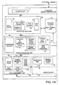
- Figure 1 illustrates one embodiment of a virtual machine instruction hardware processor 100, hereinafter hardware processor 100, that includes an instruction decoder 135 for folding a sequence of multiple instructions into a single folded operation in accordance with the present invention, and that directly executes virtual machine instructions that are processor architecture independent.
- the performance of hardware processor 100 in executing virtual machine instructions is much better than high-end CPUs, such as the Intel PENTIUM microprocessor or the Sun Microsystems ULTRASPARC processor, (ULTRASPARC is a trademark of Sun Microsystems of Mountain View, CA., and PENTIUM is a trademark of Intel Corp.
- Hardware processor 100 provides similar advantages for other virtual machine stack-based architectures as well as for virtual machines utilizing features such as garbage collection, thread synchronization, etc.
- a system based on hardware processor 100 presents attractive price for performance characteristics, if not the best overall performance, as compared with alternative virtual machine execution environments including software interpreters and just-in-time compilers. Nonetheless, the present invention is not limited to virtual machine hardware processor embodiments, and encompasses any suitable stack-based, or non-stack-based, machine implementations, including implementations emulating the JAVA virtual machine as a software interpreter, compiling JAVA virtual machine instructions (either in batch or just-in-time) to machine instruction native to a particular hardware processor, or providing hardware implementing the JAVA virtual machine in microcode, directly in silicon, or in some combination thereof.
- hardware processor 100 has the advantage that the 250 Kilobytes to 500 Kilobytes (Kbytes) of memory storage, e.g., read-only memory or random access memory, typically required by a software interpreter, is eliminated.
- a simulation of hardware processor 100 showed that hardware processor 100 executes virtual machine instructions twenty times faster than a software interpreter running on a variety of applications on a PENTIUM processor clocked at the same clock rate as hardware processor 100, and executing the same virtual machine instructions.
- Another simulation of hardware processor 100 showed that hardware processor 100 executes virtual machine instructions five times faster than a just-in-time compiler running on a PENTIUM processor running at the same clock rate as hardware processor 100, and executing the same virtual machine instructions.
- hardware processor 100 is advantageous. These applications include, for example, an Internet chip for network appliances, a cellular telephone processor, other telecommunications integrated circuits, or other low-power, low-cost applications such as embedded processors, and portable devices.
- Instruction decoder 135, as described herein, allows the folding away of JAVA virtual machine instructions pushing an operand onto the top of a stack merely as a precursor to a second JAVA virtual machine instruction which operates on the top of stack operand.
- Such an instruction decoder identifies foldable instruction sequences and supplies an execution unit with a single equivalent folded operation thereby reducing processing cycles otherwise required for execution of multiple operations corresponding to the multiple instructions of the folded instruction sequence.
- Instruction decoder embodiments described herein provide for folding of two, three, four, or more instruction folding. For example, in one instruction decoder embodiment described herein, two load instructions and a store instruction can be folded into execution of operation corresponding to an instruction appearing therebetween in the instruction sequence.
- a virtual machine is an abstract computing machine that, like a real computing machine, has an instruction set and uses various memory areas.
- a virtual machine specification defines a set of processor architecture independent virtual machine instructions that are executed by a virtual machine implementation, e.g., hardware processor 100.
- Each virtual machine instruction defines a specific operation that is to be performed.
- the virtual computing machine need not understand the computer language that is used to generate virtual machine instructions or the underlying implementation of the virtual machine. Only a particular file format for virtual machine instructions needs to be understood.
- the virtual machine instructions are JAVA virtual machine instructions.
- Each JAVA virtual machine instruction includes one or more bytes that encode instruction identfying information, operands, and any other required information.
- Appendix I which is incorporated herein by reference in its entirety, includes an illustrative set of the JAVA virtual machine instructions.
- the particular set of virtual machine instructions utilized is not an essential aspect of this invention.
- those of skill in the art can modify the invention for a particular set of virtual machine instructions, or for changes to the JAVA virtual machine specification..
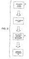
- a JAVA compiler JAVAC ( Fig. 2 ) that is executing on a computer platform, converts an application 201 written in the JAVA computer language to an architecture neutral object file format encoding a compiled instruction sequence 203, according to the JAVA Virtual Machine Specification, that includes a compiled instruction set.
- a source of virtual machine instructions and related information is needed. The method or technique used to generate the source of virtual machine instructions and related information is not essential to this invention.
- Compiled instruction sequence 203 is executable on hardware processor 100 as well as on any computer platform that implements the JAVA virtual machine using, for example, a software interpreter or just-in-time compiler.
- hardware processor 100 provides significant performance advantages over the software implementations.
- hardware processor 100 processes the JAVA virtual machine instructions, which include bytecodes.
- Hardware processor 100 executes directly most of the bytecodes. However, execution of some of the bytecodes is implemented via microcode.
- firmware means microcode stored in ROM that when executed controls the operations of hardware processor 100.
- hardware processor 100 includes an I/O bus and memory interface unit 110, an instruction cache unit 120 including instruction cache 125, an instruction decode unit 130, a unified execution unit 140, a stack management unit 150 including stack cache 155, a data cache unit 160 including a data cache 165, and program counter and trap control logic 170. Each of these units is described more completely below.
- each unit includes several elements.
- the interconnections between elements within a unit are not shown in Figure 1 .
- those of skill in the art will understand the interconnections and cooperation between the elements in a unit and between the various units.
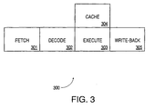
- the pipeline stages implemented using the units illustrated in Figure 1 include fetch, decode, execute, and write-back stages. If desired, extra stages for memory access or exception resolution are provided in hardware processor 100.
- Figure 3 is an illustration of a four stage pipeline for execution of instructions in the exemplary embodiment of processor 100.
- fetch stage 301 a virtual machine instruction is fetched and placed in instruction buffer 124 ( Fig. 1 ).
- the virtual machine instruction is fetched from one of (i) a fixed size cache line from instruction cache 125 or (ii) microcode ROM 141 in execution unit 140 .
- each virtual machine instruction is between one and five bytes long. Thus, to keep things simple, at least forty bits are required to guarantee that all of a given instruction is contained in the fetch.
- Another alternative is to always fetch a predetermined number of bytes, for example, four bytes, starting with the opcode. This is sufficient for 95% of JAVA virtual machine instructions (See Appendix I). For an instruction requiring more than three bytes of operands, another cycle in the front end must be tolerated if four bytes are fetched. In this case, the instruction execution can be started with the first operands fetched even if the full set of operands is not yet available.
- decode stage 302 ( Fig. 3 ) the virtual machine instruction at the front of instruction buffer 124 ( Fig. 1 ) is decoded and instruction folding is performed if possible.
- Stack cache 155 is accessed only if needed by the virtual machine instruction.
- Register OPTOP that contains a pointer OPTOP to a top of a stack 400 ( Figs. 4A and 4B ) is also updated in decode stage 302 ( Fig. 3 ).
- a register to store a pointer is illustrative only of one embodiment.
- the pointer may be implemented using a hardware register, a hardware counter, a software counter, a software pointer, or other equivalent embodiments known to those of skill in the art.
- the particular implementation selected is not essential to the invention, and typically is made based on a price to performance trade-off.
- execute stage 303 the virtual machine instruction is executed for one or more cycles.
- an ALU in integer unit 142 ( Fig. 1 ) is used either to do an arithmetic computation or to calculate the address of a load or a store from data cache unit (DCU) 160. If necessary, traps are prioritized and taken at the end of execute stage 303 ( Fig. 3 ).
- the branch address is calculated in execute stage 303, as well as the condition upon which the branch is dependent.
- Cache stage 304 is a non-pipelined stage.
- Data cache 165 ( Fig. 1 ) is accessed if needed during execution stage 303 ( Fig. 3 ).
- stage 304 is non-pipelined is because hardware processor 100 is a stack-based machine.
- the instruction following a load is almost always dependent on the value returned by the load. Consequently, in this embodiment, the pipeline is held for one cycle for a data cache access. This reduces the pipeline stages, and the die area taken by the pipeline for the extra registers and bypasses.
- Write-back stage 305 is the last stage in the pipeline. In stage 305, the calculated data is written back to stack cache 155.
- Hardware processor 100 directly implements a stack 400 ( Fig. 4A ) that supports the JAVA virtual machine stack-based architecture (See Appendix 1).
- a stack 400 ( Fig. 4A ) that supports the JAVA virtual machine stack-based architecture (See Appendix 1).
- Sixty-four entries on stack 400 are contained on stack cache 155 in stack management unit 150. Some entries in stack 400 may be duplicated on stack cache 155. Operations on data are performed through stack cache 155.
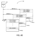
- Stack 400 of hardware processor 100 is primarily used as a repository of information for methods. At any point in time, hardware processor 100 is executing a single method. Each method has memory space, i.e., a method frame on stack 400, allocated for a set of local variables, an operand stack, and an execution environment structure.
- a new method frame e.g., method frame two 410
- Current frame 410 ( Fig. 4A ), as well as the other method frames, may contain a part of or all of the following six entities, depending on various method invoking situations:
- object reference, incoming arguments, and local variables are included in arguments and local variables area 421.
- the invoker's method context is included in execution environment 422, sometimes called frame state, that in turn includes: a return program counter value 431 that is the address of the virtual machine instruction, e.g., JAVA opcode, next to the method invoke instruction; a return frame 432 that is the location of the calling method's frame; a return constant pool pointer 433 that is a pointer to the calling method's constant pool table; a current method vector 434 that is the base address of the current method's vector table; and a current monitor address 435 that is the address of the current method's monitor.
- a return program counter value 431 that is the address of the virtual machine instruction, e.g., JAVA opcode, next to the method invoke instruction
- a return frame 432 that is the location of the calling method's frame
- a return constant pool pointer 433 that is a pointer to the calling method's constant pool
- the object reference is an indirect pointer to an object-storage representing the object being targeted for the method invocation.
- JAVA compiler JAVAC See Fig. 2 .
- This object reference is accessible as local variable zero during the execution of the method.
- This indirect pointer is not available for a static method invocation as there is no target-object defined for a static method invocation.
- the list of incoming arguments transfers information from the calling method to the invoked method. Like the object reference, the incoming arguments are pushed onto stack 400 by JAVA compiler generated instructions and may be accessed as local variables.
- JAVA compiler JAVAC See Fig. 2
- statically generates a list of arguments for current method 410 Fig. 4A
- hardware processor 100 determines the number of arguments from the list
- the object reference is present in the frame for a non-static method invocation
- the first argument is accessible as local variable one.
- the first argument becomes local variable zero.
- the upper 32-bits i.e., the 32 most significant bits, of a 64-bit entity are placed on the upper location of stack 400, i.e., pushed on the stack last.
- the upper 32-bit portion of the 64-bit entity is on the top of the stack, and the lower 32-bit portion of the 64-bit entity is in the storage location immediately adjacent to the top of stack 400.
- the local variable area on stack 400 ( Fig. 4A ) for current method 410 represents temporary variable storage space,which is allocated and remains effective during invocation of method 410.
- JAVA compiler JAVAC ( Fig. 2 ) statically determines the required number of local variables and hardware processor 100 allocates temporary variable storage space accordingly.
- the local variables When a method is executing on hardware processor 100, the local variables typically reside in stack cache 155 and are addressed as offsets from the pointer VARS ( Figs. 1 and 4A ), which points to the position of the local variable zero. Instructions are provided to load the values of local variables onto operand stack 423 and store values from operand stack into local variables area 421.
- the information in execution environment 422 includes the invoker's method context.
- hardware processor 100 pushes the invoker's method context onto newly allocated frame 410, and later utilizes the information to restore the invoker's method context before returning.
- Pointer FRAME ( Figs. 1 and 4A ) is a pointer to the execution environment of the current method.
- each register in register set 144 ( Fig. 1 ) is 32-bits wide.
- Operand stack 423 is allocated to support the execution of the virtual machine instructions within the current method.
- Program counter register PC ( Fig. 1 ) contains the address of the next instruction, e.g., opcode, to be executed. Locations on operand stack 423 ( Fig.
- operand stack 423 are used to store the operands of virtual machine instructions, providing both source and target storage locations for instruction execution.
- the size of operand stack 423 is statically determined by JAVA compiler JAVAC ( Fig. 2 ) and hardware processor 100 allocates space for operand stack 423 accordingly.
- Register OPTOP Figs. 1 and 4A ) holds a pointer to a top of operand stack 423.
- the invoked method may return its execution result onto the invoker's top of stack, so that the invoker can access the return value with operand stack references.
- the return value is placed on the area where an object reference or an argument is pushed before a method invocation.
- One way to speed up this process is for hardware processor 100 to load the execution environment in the background and indicate what has been loaded so far, e.g., simple one bit scoreboarding. Hardware processor 100 tries to execute the bytecodes of the called method as soon as possible, even though stack 400 is not completely loaded. If accesses are made to variables already loaded, overlapping of execution with loading of stack 400 is achieved, otherwise a hardware interlock occurs and hardware processor 100 just waits for the variable or variables in the execution environment to be loaded.
- Figure 4B illustrates another way to accelerate method invocation.
- the execution environment of each method frame is stored separately from the local variable area and the operand stack of the method frame.
- stack 400B contains modified method frames, e.g., modified method frame 410B having only local variable area 421 and operand stack 423.
- Execution environment 422 of the method frame is stored in an execution environment memory 440. Storing the execution environment in execution environment memory 440 reduces the amount of data in stack cache 155. Therefore, the size of stack cache 155 can be reduced. Furthermore, execution environment memory 440 and stack cache 155 can be accessed simultaneously. Thus, method invocation can be accelerated by loading or storing the execution environment in parallel with loading or storing data onto stack 400B.
- the memory architecture of execution environment memory 440 is also a stack. As modified method frames are pushed onto stack 400B through stack cache 155, corresponding execution environments are pushed onto execution environment memory 440. For example, since modified method frames 0 to 2, as shown in Figure 4B , are in stack 400B, execution environments (EE) 0 to 2, respectively, are stored in execution environment memory circuit 440.
- EE execution environments
- an execution environment cache can be added to improve the speed of saving and retrieving the execution environment during method invocation.
- the architecture described more completely below for stack cache 155, dribbler manager unit 151, and stack control unit 152 for caching stack 400, can also be applied to caching execution environment memory 440.
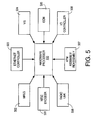
- Figure 4C illustrates an embodiment of stack management unit 150 modified to support both stack 400B and execution environment memory 440.
- the embodiment of stack management unit 150 in Figure 4C adds an execution environment stack cache 450, an execution environment dribble manager unit 460, and an execution environment stack control unit 470.
- execution dribble manager unit 460 transfers an entire execution environment between execution environment cache 450 and execution environment memory 440 during a spill operation or a fill operation.
- I/O bus and memory interface unit 110 implements an interface between hardware processor 100 and a memory hierarchy which in an exemplary embodiment includes external memory and may optionally include memory storage and/or interfaces on the same die as hardware processor 100.
- I/O controller 111 interfaces with external I/O devices and memory controller 112 interfaces with external memory.
- external memory means memory external to hardware processor 100.
- external memory either may be included on the same die as hardware processor 100, may be external to the die containing hardware processor 100, or may include both on- and off-die portions.
- requests to I/O devices go through memory controller 112, which maintains an address map of the entire system including hardware processor 100.
- hardware processor 100 is the only master and does not have to arbitrate to use the memory bus.
- alternatives for the input/output bus that interfaces with I/O bus and memory interface unit 110 include supporting memory-mapped schemes, providing direct support for PCI, PCMCIA, or other standard busses.
- Fast graphics w/ VIS or other technology may optionally be included on the die with hardware processor 100.
- I/O bus and memory interface unit 110 generates read and write requests to external memory.
- interface unit 110 provides an interface for instruction cache and data cache controllers 121 and 161 to the external memory.
- Interface unit 110 includes arbitration logic for internal requests from instruction cache controller 121 and data cache controller 161 to access external memory and in response to a request initiates either a read or a write request on the memory bus to the external memory.
- a request from data cache controller 161 is always treated as higher priority relative to a request from instruction cache controller 121.
- Interface unit 110 provides an acknowledgment signal to the requesting instruction cache controller 121, or data cache controller 161 on read cycles so that the requesting controller can latch the data. On write cycles, the acknowledgment signal from interface unit 110 is used for flow control so that the requesting instruction cache controller 121 or data cache controller 161 does not generate a new request when there is one pending. Interface unit 110 also handles errors generated on the memory bus to the external memory.
- Instruction cache unit (ICU) 120 fetches virtual machine instructions from instruction cache 125 and provides the instructions to instruction decode unit 130.
- instruction cache controller 121 upon a instruction cache hit, instruction cache controller 121, in one cycle, transfers an instruction from instruction cache 125 to instruction buffer 124 where the instruction is held until integer execution unit IEU, that is described more completely below, is ready to process the instruction. This separates the rest of pipeline 300 ( Fig. 3 ) in hardware processor 100 from fetch stage 301. If it is undesirable to incur the complexity of supporting an instruction-buffer type of arrangement, a temporary one instruction register is sufficient for most purposes. However, instruction fetching, caching, and buffering should provide sufficient instruction bandwidth to support instruction folding as described below.
- the front end of hardware processor 100 is largely separate from the rest of hardware processor 100. Ideally, one instruction per cycle is delivered to the execution pipeline.
- the instructions are aligned on an arbitrary eight-bit boundary by byte aligner circuit 122 in response to a signal from instruction decode unit 130.
- byte aligner circuit 122 in response to a signal from instruction decode unit 130.
- the front end of hardware processor 100 efficiently deals with fetching from any byte position.
- hardware processor 100 deals with the problems of instructions that span multiple cache lines of cache 125. In this case, since the opcode is always the first byte, the design is able to tolerate an extra cycle of fetch latency for the operands. Thus, a very simple de-coupling between the fetching and execution of the bytecodes is possible.
- instruction cache controller 121 In case of an instruction cache miss, instruction cache controller 121 generates an external memory request for the missed instruction to I/O bus and memory interface unit 110. If instruction buffer 124 is empty, or nearly empty, when there is an instruction cache miss, instruction decode unit 130 is stalled, i.e., pipeline 300 is stalled. Specifically, instruction cache controller 121 generates a stall signal upon a cache miss which is used along with an instruction buffer empty signal to determine whether to stall pipeline 300. Instruction cache 125 can be invalidated to accommodate self-modifying code, e.g., instruction cache controller 121 can invalidate a particular line in instruction cache 125.
- instruction cache controller 121 determines the next instruction to be fetched, i.e., which instruction in instruction cache 125 needs to accessed, and generates address, data and control signals for data and tag RAMs in instruction cache 125. On a cache hit, four bytes of data are fetched from instruction cache 125 in a single cycle, and a maximum of four bytes can be written into instruction buffer 124.
- Byte aligner circuit 122 aligns the data out of the instruction cache RAM and feeds the aligned data to instruction buffer 124. As explained more completely below, the first two bytes in instruction buffer 124 are decoded to determine the length of the virtual machine instruction. Instruction buffer 124 tracks the valid instructions in the queue and updates the entries, as explained more completely below.
- Instruction cache controller 121 also provides the data path and control for handling instruction cache misses. On an instruction cache miss, instruction cache controller 121 generates a cache fill request to I/O bus and memory interface unit 110.
- instruction cache controller 121 On receiving data from external memory, instruction cache controller 121 writes the data into instruction cache 125 and the data are also bypassed into instruction buffer 124. Data are bypassed to instruction buffer 124 as soon as the data are available from external memory, and before the completion of the cache fill.
- Instruction cache controller 121 continues fetching sequential data until instruction buffer 124 is full or a branch or trap has taken place.
- instruction buffer 124 is considered full if there are more than eight bytes of valid entries in buffer 124.
- eight bytes of data are written into instruction cache 125 from external memory in response to the cache fill request sent to interface unit 110 by instruction cache unit 120. If there is a branch or trap taken while processing an instruction cache miss, only after the completion of the miss processing is the trap or branch executed.
- a fault indication is generated and stored into instruction buffer 124 along with the virtual machine instruction, i.e., a fault bit is set.
- the line is not written into instruction cache 125.
- the erroneous cache fill transaction acts like a non-cacheable transaction except that a fault bit is set.
- Instruction cache controller 121 also services non-cacheable instruction reads.
- An instruction cache enable (ICE) bit in a processor status register in register set 144, is used to define whether a load can be cached. If the instruction cache enable bit is cleared, instruction cache unit 120 treats all loads as non-cacheable loads.
- Instruction cache controller 121 issues a non-cacheable request to interface unit 110 for non-cacheable instructions. When the data are available on a cache fill bus for the non-cacheable instruction, the data are bypassed into instruction buffer 124 and are not written into instruction cache 125.
- ICE instruction cache enable
- instruction cache 125 is a direct-mapped, eight-byte line size cache. Instruction cache 125 has a single cycle latency.
- the cache size is configurable to 0K, 1K, 2K, 4K, 8K and 16K byte sizes where K means kilo.
- the default size is 4K bytes.
- Each line has a cache tag entry associated with the line. Each cache tag contains a twenty bit address tag field and one valid bit for the default 4K byte size.
- Instruction buffer 124 which, in an exemplary embodiment, is a twelve-byte deep first-in, first-out (FIFO) buffer, de-links fetch stage 301 ( Fig. 3 ) from the rest of pipeline 300 for performance reasons.
- Each instruction in buffer 124 ( Fig. 1 ) has an associated valid bit and an error bit. When the valid bit is set, the instruction associated with that valid bit is a valid instruction. When the error bit is set, the fetch of the instruction associated with that error bit was an erroneous transaction.
- Instruction buffer 124 includes an instruction buffer control circuit (not shown) that generates signals to pass data to and from instruction buffer 124 and that keeps track of the valid entries in instruction buffer 124, i.e., those with valid bits set.
- instruction buffer 124 in an exemplary embodiment, four bytes can be received into instruction buffer 124 in a given cycle. Up to five bytes, representing up to two virtual machine instructions, can be read out of instruction buffer 124 in a given cycle. Alternative embodiments, particularly those providing folding of multi-byte virtual machine instructions and/or those providing folding of more than two virtual machine instructions, provide higher input and output bandwidth. Persons of ordinary skill in the art will recognize a variety of suitable instruction buffer designs including, for example, alignment logic, circular buffer design, etc. When a branch or trap is taken, all the entries in instruction buffer 124 are nullified and the branch/trap data moves to the top of instruction buffer 124.
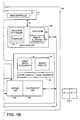
- a unified execution unit 140 is shown.
- instruction decode unit 130,integer unit 142, and stack management unit 150 are considered a single integer execution unit
- floating point execution unit 143 is a separate optional unit.
- the various elements in the execution unit may be implemented using the execution unit of another processor.
- the various elements included in the various units of Figure 1 are exemplary only of one embodiment. Each unit could be implemented with all or some of the elements shown. Again, the decision is largely dependent upon a price vs. performance trade-off.
- virtual machine instructions are decoded in decode stage 302 ( Fig. 3 ) of pipeline 300.
- two bytes that can correspond to two virtual machine instructions, are fetched from instruction buffer 124 ( Fig. 1 ).
- the two bytes are decoded in parallel to determine if the two bytes correspond to two virtual machine instructions, e.g., a first load top of stack instruction and a second add top two stack entries instruction, that can be folded into a single equivalent operation. Folding refers to supplying a single equivalent operation corresponding to two or more virtual machine instructions.
- a single-byte first instruction can be folded with a second instruction.
- alternative embodiments provide folding of more than two virtual machine instructions, e.g., two to four virtual machine instructions, and of muhi-byte virtual machine instructions, though at the cost of instruction decoder complexity and increased instruction bandwidth.
- the first byte which corresponds to the first virtual machine instruction, is a multi-byte instruction, the first and second instructions are not folded.
- An optional current object loader folder 132 exploits instruction folding, such as that described above and as well as in greater detail below in virtual machine instruction sequences which simulation results have shown to be particularly frequent and therefore a desirable target for optimization.
- a method invocation typically loads an object reference for the corresponding object onto the operand stack and fetches a field from tne object. Instruction folding allows this extremely common virtual machine instruction sequence to be executed using an equivalent folded operation.
- Quick variants are not part of the virtual machine instruction set (See Chapter 3 of Appendix I), and are invisible outside of a JAVA virtual machine implementation. However, inside a virtual machine implementation, quick variants have proven to be an effective optimization. (See Appendix A in Appendix I; which is an integral part of this specification.) Supporting writes for updates of various instructions to quick variants in a non-quick to quick translator cache 131 changes the normal virtual machine instruction to a quick virtual machine instruction to take advantage of the large benefits bought from the quick variants.
- the information required to initiate execution of an instruction has been assembled for the first time, the information is stored in a cache along with the value of program counter PC as tag in non-quick to quick translator cache 131 and the instruction is identified as a quick-variant. In one embodiment, this is done with self-modifying code.
- instruction decode unit 130 Upon a subsequent call of that instruction, instruction decode unit 130 detects that the instruction is identified as a quick-variant and simply retrieves the information needed to initiate execution of the instruction from non-quick to quick translator cache 131.
- Non-quick to quick translator cache is an optional feature of hardware processor 100.
- branch predictor circuit 133 branch predictor circuit 133.
- Implementations for branch predictor circuit 133 include branching based on opcode, branching based on offset, or branching based on a two-bit counter mechanism.
- Operand stack 423 contains a reference to an object and some number of arguments when this instruction is executed.
- Index bytes one and two are used to generate an index into the constant pool of the current class.
- the item in the constant pool at that index points to a complete method signature and class. Signatures are defined in Appendix I and that description is incorporated herein by reference.
- the method signature a short, unique identifier for each method, is looked up in a method table of the class indicated.
- the result of the lookup is a method block that indicates the type of method and the number of arguments for the method.
- the object reference and arguments are popped off this method's stack and become initial values of the local variables of the new method.
- the execution then resumes with the first instruction of the new method.
- instructions invokevirtual , opcode 182, and invokestatic, opcode 184 invoke processes similar to that just described. In each case, a pointer is used to lookup a method block.
- a method argument cache 134 that also is an optional feature of hardware processor 100, is used, in a first embodiment, to store the method block of a method for use, after the first call to the method, along with the pointer to the method block as a tag.
- Instruction decode unit 130 uses index bytes one and two to generate the pointer and then uses the pointer to retrieve the method block for that pointer in cache 134. This permits building the stack frame for the newly invoked method more rapidly in the background in subsequent invocations of the method.
- Alternative embodiments may use a program counter or method identifier as a reference into cache 134. If there is a cache miss, the instruction is executed in the normal fashion and cache 134 is updated accordingly.
- the particular process used to determine which cache entry is overwritten is not an essential aspect of this invention. A least-recently used criterion could be implemented, for example.
- method argument cache 134 is used to store the pointer to the method block, for use after the first call to the method, along with the value of program counter PC of the method as a tag.
- Instruction decode unit 130 uses the value of program counter PC to access cache 134. If the value of program counter PC is equal to one of the tags in cache 134, cache 134 supplies the pointer stored with that tag to instruction decode unit 130. Instruction decode unit 130 uses the supplied pointer to retrieve the method block for the method.
- Wide index forwarder 136 which is an optional element of hardware processor 100, is a specific embodiment of instruction folding for instruction wide. Wide index forwarder 136 handles an opcode encoding an extension of an index operand for an immediately subsequent virtual machine instruction. In this way, wide index forwarder 136 allows instruction decode unit 130 to provide indices into local variable storage 421 when the number of local variables exceeds that addressable with a single byte index without incurring a separate execution cycle for instruction wide..
- instruction decoder 135, particularly instruction folding, non-quick to quick translator cache 131, current object loader folder 132, branch predictor 133, method argument cache 134, and wide index forwarder 136 are also useful in implementations that utilize a software interpreter or just-in-time compiler, since these elements can be used to accelerate the operation of the software interpreter or just-in-time compiler.
- the virtual machine instructions are translated to an instruction for the processor executing the interpreter or compiler, e.g., any one of a Sun processor, a DEC processor, an Intel processor, or a Motorola processor, for example, and the operation of the elements is modified to support execution on that processor.
- the translation from the virtual machine instruction to the other processor instruction can be done either with a translator in a ROM or a simple software translator.
- processor 100 implements instruction folding to enhance the performance of processor 100.
- instruction folding in accordance with the present invention can be used in any of a stack-based virtual machine implementation, including, e.g., in a hardware processor implementation, in a software interpreter implementation, in a just-in-time compiler implementation. etc.
- Figure 7 illustrates folded execution of first and second stack instructions, according to the principles of this invention.
- a first operand for an addition instruction resides in top-of-stack (TOS) entry 711a of stack 710.
- a second operand resides in entry 712 of stack 710. Notice that entry 712 is not physically adjacent to top-of stack entry 711a and in fact, is in the interior of stack 710.
- An instruction stream includes a load top-of-stack instruction for pushing the second operand onto the top of stack (see description of instruction iload in Appendix I) and an addition instruction for operating on the first and second operands residing in the top two entries of stack 710 (see description of instruction iadd in Appendix I).
- the load top-of-stack and addition instructions are folded into a single operation whereby the explicit sequential execution of the load top-of-stack instruction and the associated execution cycle are eliminated. Instead, a folded operation corresponding to the addition instruction operates on the first and second operands, which reside in TOS entry 711a and entry 712 of stack 710. The result of the folded operation is pushed onto stack 710 at TOS entry 711b .
- folding according to the principles of this invention enhances performance compared to an unfolded method for executing the same sequence of instructions.
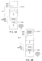
- a first operand for an addition instruction resides in top-of-stack (TOS) entry 611a of stack 610 (see Figure 6 ).
- a second operand resides in entry 612 of stack 610.
- a load to top-of-stack instruction pushes the second operand onto the top of stack 610 and typically requires an execution cycle. The push results in the second and first operands residing in TOS entry 611b and (TOS-1) entry 613, respectively.
- the addition instruction operates, in another execution cycle, on the first and second operands which properly reside in the top two entries, i.e., TOS entry 611b and (TOS-1) entry 613, of stack 610 in accordance with the semantics of a stack architecture.
- the result of the addition instruction is pushed onto stack 610 at TOS entry 611c and after the addition instruction is completed, it is as if the first and second operand data were never pushed onto stack 610.
- folding reduces the execution cycles required to complete the addition and so enhances the speed of execution of the instruction stream. More complex folding, e.g., folding including store instructions and folding including larger numbers of instructions, is described in greater detail below.
- instruction decoder unit 130 examines instructions in a stream of instructions. Instruction decoder unit 130 folds first and second adjacent instructions together and provides a single equivalent operation for execution by execution unit 140 when instruction decoder unit 130 detects that the first and second instructions have neither structural nor resource dependencies and the second instruction operates on data provided by the first instruction. Execution of the single operations obtains the same result as execution of an operation corresponding to the first instruction followed by execution an operation corresponding to the second instruction, except that an execution cycle has been eliminated.
- the JAVA virtual machine is stack-oriented and specifies an instruction set, a register set, an operand stack, and an execution environment.
- the present invention is described in relation to the JAVA Virtual Machine, those of skill in the art will appreciate that the invention is not limited to embodiments implementing or related to the JAVA virtual machine and, instead, encompasses systems, articles, methods, and apparati for a wide variety of stack machine environments, both virtual and physical.
- each method has storage allocated for an operand stack and a set of local variables.
- a series of method frames e.g., method frame 801 and method frame 802 on stack 803, each include an operand stack instance, local variable storage instance, and frame state information instance for respective methods invoked along the execution path of a JAVA program.
- a new frame is created and becomes current each time a method is invoked and is destroyed after the method completes execution.
- a frame ceases to be current if its method invokes another method.
- the current frame passes back the result of its method invocation, if any, to the previous frame via stack 803.
- Folding in accordance with the present invention is not dependent upon a particular process used to allocate or define memory space for a method, such as a frame, and can, in general, be used in any stack based architecture.
- This series of method frames may be implemented in any of a variety of suitable memory hierarchies, including for example register/ cache/ memory hierarchies.
- an operand stack instance 812 ( Figure 8 ) is implemented in randomly-accessible storage 810, i.e., at least some of the entries in operand stack instance 812 can be accessed from locations other than the top most locations of operand stack instance 812 in contrast with a conventional stack implementation in which only the top entry or topmost entries of the stack can be accessed.
- register OPTOP stores a pointer that identifies the top of operand stack instance 812 associated with the current method. The value stored in register OPTOP is maintained to identify the top entry of an operand stack instance corresponding to the current method.
- local variables for the current method are represented in randomly-accessible storage 810.
- a pointer stored in register VARS identifies the starting address of local variable storage instance 813 associated with the current method.
- the value in register VARS is maintained to identify a base address of the local variable storage instance corresponding to the current method.
- Entries in operand stack instance 812 and local variable storage instance 813 are referenced by indexing off of values represented in registers OPTOP and VARS, respectively, that in the embodiment of Figure 1 are included in register set 144, and in the embodiment of Figure 8 are included in pointer registers 822.
- Pointer registers 822 may be represented in physical registers of a processor implementing the JAVA Virtual Machine, or optionally, in randomly-accessible storage 810.
- commonly used offsets OPTOP-1, OPTOP-2, VARS+1, VARS+2, and VARS+3 are derived from the values in registers OPTOP and VARS, respectively.
- the additional offsets could be stored in registers of pointer registers 822.
- Operand stack instance 812 and local variable storage instance 813 associated with the current method are preferably represented in a flat 64-entry cache, e.g., stack cache 155 (see Figure 1 ) whose contents are kept updated so that a working set of operand stack and local variable storage entries are cached.
- a flat 64-entry cache e.g., stack cache 155 (see Figure 1 )
- the current frame including operand stack instance 812 and local variable storage instance 813 may be fully or partially represented in the cache.
- Operand stack and local variable storage entries for frames other than the current frame may also be represented in the cache if space allows.
- a cache suitable for use with the folding of this invention may have various representations, including separate and/or uncached operand stack and local varaible storage areas.
- a constant area 814 is provided in the address space of a processor implementing the JAVA virtual machine for commonly-used constants, e.g., constants specified by JAVA virtual machine instructions such as instruction iconst.
- an operand source is represented as an index into constant area 814.
- constant area 814 is represented in randomly-accessible storage 810.
- entries of constant area 814 could also be cached, e.g., in stack cache 155.
- operand stack 812 and local variable storage 813 are referred to simply as operand stack 812 and local variable storage 813.
- operand stack 812 and local variable storage 813 refer to any instances of an operand stack and variable storage associated with the current method, including representations which maintain separate instances for each method and representations which combine instances into a composite representation.
- Operand sources and result targets for JAVA Virtual Machine instructions typically identify entries of operand stack instance 812 or local variable storage instance 813, i.e., identify entries of the operand stack and local variable storage for the current method.
- representative JAVA virtual machine instructions are described in Chapter 3 of The JAVA Virtual Machine Specification which is included at Appendix I.
- JAVA virtual machine instructions rarely explicitly designate both the source of the operand, or operands, and the result destination. Instead, either the source or the destination is implicitly the top of operand stack 812. Some JAVA bytecodes explicitly designate neither a source nor a destination. For example, instruction iconst_0 pushes a constant integer zero onto operand stack 812. The constant zero is implicit in the instruction, although the instruction may actually be implemented by a particular JAVA virtual machine implementation using a representation of the value zero from a pool of constants, such as constant area 814, as the source for the zero operand. An instruction decoder for a JAVA virtual machine implementation that implements instruction iconst_0 in this way could generate, as the source address, the index of the entry in constant area 814 where the constant zero is represented.
- the JAVA virtual machine integer add instruction, iadd generates the sum of first and second integer operands, referred to as operand 1 and operand2, respectively, that are at the top two locations of operand stack 812.
- the top two locations are identified, at the time of instruction iadd execution, by pointer OPTOP in register OPTOP and by pointer OPTOP-1.
- the result of the execution of instruction iadd i.e., the sum of first and second integer operands, is pushed onto operand stack 812.
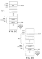
- Figure 9A shows the state of operand stack 812 and local variable storage 813 that includes first and second values, referred to as value and value2, before execution of a pair of JAVA virtual machine integer load instructions iload .
- pointer OPTOP has the value AAC0h.
- Figure 9B shows operand stack 812 after execution of the pair of instructions iload that load integer values from local variable storage 813 onto operand stack 812, pushing (i.e., copying) values value1 and value2 from locations identified by pointer VARS in register VARS and by pointer VARS+2 onto operand stack 812 as operand1 at location AAC4h and operand2 at location AAC8h, and updating pointer OPTOP in the process to value AAC8h.
- Figure 9C shows operand stack 812 after instruction iadd has been executed.
- Execution of instruction iadd pops operands operand1 and operand2 off operand stack 812, calculates the sum of operands operand1 and operand2, and pushes that sum onto operand stack 812 at location AAC4h.
- pointer OPTOP has the value AAC0h and points to the operand stack 812 entry storing the sum.
- Figure 9D shows operand stack 812 after an instruction istore has been executed. Execution of instruction istore pops the sum off operand stack 812 and stores the sum in the local variable storage 813 entry at the location identified by pointer VARS+2.
- FIG. 10A-C The folding example of Figures 10A-C is analogous to that illustrated with reference to Figures 9A-D , though with only load folding illustrated.
- Execution of JAVA virtual machine length of array instruction arraylength determines the length of an array whose object reference pointer objectref is at the top of operand stack 812, and pushes the length onto operand stack 812.
- Figure 10A shows the state of operand stack 812 and local variable storage 813 before execution of JAVA virtual machine reference load instruction aload that is used to load an object reference from local variable storage 813 onto the top of operand stack 812.
- pointer OPTOP has the value AAC0h.
- Figure 10B shows operand stack 812 after execution of instruction aload pushes, i.e., copies, object reference pointer objectref onto the top of operand stack 812 and updates pointer OPTOP to AAC4h in the process.
- Figure 10C shows operand stack 812 after instruction arraylength has been executed.
- Execution of instruction arraylength pops object reference pointer objectref off operand stack 812, calculates the length of the array referenced thereby, and pushes that length onto operand stack 812.
- Suitable implementations of the instruction arraylength may supply object reference pointer objectref to an execution unit, e.g., execution unit 140, which subsequently overwrites the object reference pointer objectref with the value length.
- execution unit 140 e.g., execution unit 140
- pointer OPTOP has the value AAC4h and points to the operand stack 812 entry storing the value length.
- Figure 1 illustrates a processor 1100 wherein loads, such as those illustrated in Figures 9A and 9B and in Figures 10A and 10B , are folded into execution of subsequent instructions, e.g., into execution of subsequent instruction iadd, or instruction arraylength.
- loads such as those illustrated in Figures 9A and 9B and in Figures 10A and 10B
- subsequent instructions e.g., into execution of subsequent instruction iadd, or instruction arraylength.
- intermediate execution cycles associated with loading operands operand 1 and operand2 for instruction iadd, or with loading pointer objectref for instruction arraylength onto the top of operand stack 812 can be eliminated.
- single cycle execution of groups of JAVA virtual machine instructions e.g., the group of instructions iload, iload, iadd, and istore , or the group of instructions aload and arraylength, is provided by processor 1100.
- processor 1100 is presented in Figure 1 as hardware processor 100.
- hardware processor 1100 includes other embodiments that do not include the various optimizations of hardware processor 100.
- the folding processes described below could be implemented in a software interpreter or a included within a just-in-time compiler.
- stores such as that illustrated in Figure 9D are folded into execution of prior instructions, e.g., in Figure 9D , into execution of the immediately prior instruction iadd .
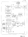
- Instruction decoder 1118 retrieves fetched instructions from instruction buffer 1116 and depending upon the nature of instructions in the fetched instruction sequence, supplies execution unit 1120 with decoded operation and operand addressing information implementing the instruction sequence as a single folded operation. Unlike instructions of the JAVA virtual machine instruction set to which the instruction sequence from instruction buffer 1116 conforms, decoded operations supplied to execution unit 1120 by instruction decoder 1118 operate on operand values represented in entries of local variable storage 813, operand stack 812, and constant area 814.
- valid operand sources include local variable storage 813 entries identified by pointers VARS, VARS+1 , VARS+2, and VARS+3, as well as operand stack 812 entries identified by pointers OPTOP, OPTOP-1, and OPTOP-2.
- valid result targets include local variable storage 813 entries identified by operands VARS, VARS+1, VARS+2, and VARS+3.
- Embodiments in accordance with Figure 11 may also provide for constant area 814 entries as valid operand sources as well as other locations in operand stack 812 and local variable storage 813.
- instruction buffer 1116 is organized as a shift register for JAVA bytecodes.
- One or more bytecodes are decoded by instruction decoder 1118 during each cycle and operations are supplied to execution unit 1120 in the form of a decoded operation on instruction decode bus instr_dec and associated operand source and result destination addressing information on instruction address bus instr_addr .
- Instruction decoder 1118 also provides an instruction valid signal instr_valid to execution unit 1120. When asserted, signal instr_valid indicates that the information on instruction decode bus instr_dec specifies a valid operation.
- One or more bytecodes are shifted out of instruction buffer 1116 to instruction decode unit 1118 each cycle in correspondence with the supply of decoded operations and operand addressing information to execution unit 1120, and subsequent undecoded bytecodes are shifted into instruction buffer 1116.
- instruction buffer 1116 For normal decode operations, a single instruction is shifted out of instruction buffer 1116 and decoded by instruction decode unit 1118, and a single corresponding operation is executed by execution unit 1120 during each instruction cycle.
- instruction decode unit 1118 For folded decode operations, multiple instructions, e.g., a group of instructions, are shifted out of instruction buffer 1116 to instruction decode unit 1118. In response to the multiple instructions, instruction decode unit 1118 generates a single equivalent folded operation that in turn is executed by execution unit 1120 during each instruction cycle.
- instruction decoder 1118 selectively decodes bytecodes associated with four JAVA virtual machine instructions:
- Instruction decoder 1118 supplies decoded operation information over bus instr_dec and associated operand source and result destination addressing information over bus instr_addr specifying that execution unit 1120 is to add the contents of local variable storage 813 location 0, this is identified by pointer VARS, and local variable storage 813 location 2, that is identified by pointer VARS+2, and store the result in local variable storage 813 location 2, that is identified by pointer VARS+2.
- execution unit 1120 is to add the contents of local variable storage 813 location 0, this is identified by pointer VARS, and local variable storage 813 location 2, that is identified by pointer VARS+2, and store the result in local variable storage 813 location 2, that is identified by pointer VARS+2.
- the two load instructions are folded into execution of an operation corresponding to instruction iadd .
- Two instruction cycles and the intermediate data state illustrated in Figure 9B are eliminated.
- instruction istore is also folded into execution of the operation corresponding to instruction iadd , eliminating another instruction cycle, for a total of three, and the intermediate data state illustrated in Figure 9C .
- instruction folding in accordance with the present invention may eliminate loads, stores, or both loads and stores.
- Figure 13 depicts an exemplary embodiment of an instruction decoder 1118 providing both folded and unfolded decoding of bytecodes. Selection of a folded or unfolded operating mode for instruction decoder 1118 is based on the particular sequence of bytecodes fetched into instruction buffer 1116 and subsequently accessed by instruction decoder 1118.
- a normal decode portion 1302 and a fold decode portion 1304 of instruction decoder 1118 are configured in parallel to provide support for unfolded and folded execution, respectively.
- fold decode portion 1304 detects opportunities for folding execution of bytecodes in the bytecode sequence fetched into instruction buffer 1116. A detection of such a foldable sequence triggers selection of the output of fold decode portion 1304, rather than normal decode portion 1302, for provision to execution unit 1120.
- selection of folded or unfolded decoding is transparent to execution unit 1120, which simply receives operation information over bus instr_dec and associated operand source and result destination addressing information over bus instr_addr, and which need not know whether the information corresponds to a single instruction or a folded instruction sequence.
- Normal decode portion 1302 functions to inspect a single bytecode from instruction buffer 1116 during each instruction cycle, and generates the following indications in response thereto:
- fold decode portion 804 of instruction decoder 618 inspects sequences of bytecodes from the instruction buffer 616 and determines whether operations corresponding to these sequences (e.g., the sequence iload value from local variable 0, iload value2 from local variable 2, iadd, and istore sum to local variable 2) can be folded together to eliminate unnecessary temporary storage of instruction operands and/or results on the operand stack.
- fold decode portion 804 determines that a sequence of bytecodes in instruction buffer 616 can be folded together, fold decode portion 804 generates the following indications:
- the operation of fold decode portion 1304 is suppressed in response to an active suppress folding signal suppress_fold supplied from outside instruction decoder 1118.
- an asserted suppress folding signal suppress_fold (see Figure 14 )
- the signal on fold line f/nf remains in a state selective for respective first inputs of switches 1306, 1310 and 1308 even if the particular bytecode sequence presented by instruction buffer 1116 would otherwise trigger folding.
- suppress folding signal suppress_fold is asserted when the local variable storage 813 entry identified by pointer VARS is not cached, e.g., when entries in operand stack 812 have displaced local variable storage 813 from a stack cache 155.
- a stack cache and cache control mechanism representing at least a portion of operand stack 812 and local variable storage 813 may advantageously assert suppress folding signal suppress_fold if fold-relevant entries of local variable storage 813 or operand stack 812 are not represented in stack cache 155.
- Figure 14 illustrates fold decode portion 1304 of instruction decoder 1118 in greater detail.
- a fold determination portion 1404 selectively inspects the sequence of bytecodes in instruction buffer 1116. If the next bytecode and one or more subsequent bytecodes represent a foldable sequence of operations (as discussed below with respect to Figure 15 ), then fold determination portion 1404 supplies a fold-indicating signal on fold line f/nf and a folded instruction decode signal f_instr_dec that specifies an equivalent folded operation. Folded instruction decode signal f_instr_dec is supplied to execution unit 1120 as the decoded instruction instr_dec.
- a foldable sequence of operations includes those associated with 2, 3, or 4 bytecodes from instruction decoder 1118 (up to 2 bytecodes loading operands onto operand stack 812, a bytecode popping the operand(s), operating thereupon, and pushing a result onto operand stack 812, and a bytecode popping the result from operand stack 812 and storing the result.
- the equivalent folded operation which is encoded by the folded instruction decode signal f_instr_dec, specifies an operation, that when combined with folded execution addressing information obviates the loads to, and stores from, operand stack 812.
- Alternative embodiments may fold only two instructions, e.g., an instruction iload into an instruction iadd or an instruction istore back into an immediately prior instruction iadd .
- Other alternative embodiments may fold only instructions that push operands onto the operand stack, e.g., one or more instructions iload folded into an instruction iadd, or only instructions that pop results from the operand stack, e.g., an instruction istore back into an immediately prior instruction iadd.
- Further alternative embodiments may fold larger numbers of instructions that push operands onto the operand stack and/or instructions that pop results from the operand stack instructions in accordance with instructions of a particular virtual machine instruction set. In such alternative embodiments, the above described advantages over normal decoding and execution of instruction sequences are still obtained.
- Fold determination portion 1404 generates a series of fold address index composite signal f_adr_ind including component first operand index signal first_adr_ind, second operand index signal second_adr_ind, and destination index signal dest_adr_ind, which are respectively selective for a first operand address, a second operand address, and a destination address for the equivalent folded operation.
- Fold determination portion 1404 provides the composite signal f_adr_ind to fold address generator 1402 for use in supplying operand and destination addresses for the equivalent folded operation.
- Fold determination portion 1404 asserts a fold-indicating signal on fold line f/nf to control the switches 1306, 1310 and 1308 (see Figure 13 ) to provide the signals f_instr_dec, f_adr, and f_valid, as signals instr_dec, instr_adr, and instr_valid, respectively. Otherwise respective signals are provided to execution unit 1120 from normal decode portion 1302.
- fold determination portion 1404 begins an instruction decode cycle and transfers processing to initialize index 1502.
- initialize index 1502 an instruction index instr_index into instruction buffer 1116 is initialized to identify the next bytecode of a bytecode sequence in instruction buffer 1116.
- instruction index instr_index is initialed to one (1) and the next bytecode is the first bytecode in instruction buffer 1116 since prior bytecodes have already been shifted out of instruction buffer 1116, although a variety of other indexing and instruction buffer management schemes would also be suitable.
- initialize index 1502 transfers processing to first instruction check 1504.
- first instruction check 1504 determines whether the instruction identified by index instr_index, i.e., the first bytecode, corresponds to an operation that pushes a value, e.g., an integer value, a floating point value, a reference value, etc., onto operand stack 812.
- first instruction check 1504 determines whether the instruction identified by index instr_index is one that the JAVA virtual machine specification (see Appendix I) defines as for pushing a first data item onto the operand stack. If so, first operand index signal first_adr_ind is asserted (at first operand address setting 1506 ) to identify the source of the first operand value.
- first operand index signal first_adr_ind is selective for one of OPTOP, OPTOP-1, OPTOP-2, VARS, VARS+1, VARS+2, and VARS+3, although alternative embodiments may encode larger, smaller, or different sets of source addresses, including for example, source addresses in constant area 814.
- this first bytecode may correspond to an operation which can be folded into the execution of a subsequent operation.
- folding is not appropriate and fold determination portion 1404 supplies a nonfold- indicating signal on fold line f/nf, whereupon indications from normal decode portion 1302 provide the decoding.
- index instr_index is incremented (at incrementing 1508) to point to the next bytecode in instruction buffer 1116.
- fold determination portion 1404 determines whether instruction identified by index instr_index, i.e., the second bytecode, corresponds to an operation that pushes a value, e.g., an integer value, a floating point value, a reference value, etc., onto operand stack 812.
- second instruction check 1510 determines whether the instruction identified by index instr_index is one that the JAVA virtual machine specification (see Appendix I) defines as for pushing a first data item onto the operand stack. If so, second operand index signal second_adr_ind is asserted (at second operand address setting 1512) to indicate the source of the second operand value and index instr_index is incremented (at incrementing 1514) to point to the next bytecode in instruction buffer 1116.
- second operand index signal second_adr_ind is selective for one of OPTOP, OPTOP-1, OPTOP-2, VARS, VARS+1, VARS+2, and VARS+3, although alternative embodiments are also suitable.
- Fold determination portion 1404 continues at third instruction check 1516 with index instr_index pointing to either the second or third bytecode in instruction buffer 1116.
- fold determination portion 1404 determines whether the instruction identified by index instr_index, i.e., either the second or third bytecode, corresponds to an operation that operates on an operand value or values, e.g., integer value(s), floating point value(s), reference value(s), etc., from the uppermost entries of operand stack 812, effectively popping such operand values from operand stack 812 and pushing a result value onto operand stack 812. Popping of operand values may be explicit or merely a net effect of writing the result value to an upper entry of operand stack 812 and updating pointer OPTOP to identify that entry as the top of operand stack 812.
- an operand value or values e.g., integer value(s), floating point value(s), reference value(s), etc.
- third instruction check 1516 determines whether the instruction identified by index instr_index corresponds to an operation that the JAVA virtual machine specification (see Appendix 1) defines as for popping a data item (or items) from the operand stack, for operating on the popped data item(s), and for pushing a result of the operation onto the operand stack. If so, index instr_index is incremented (at incrementing 1518) to point to the next bytecode in instruction buffer 1116. If not, folding is not appropriate and fold determination portion 1404 supplies a nonfold -indicating signal on fold line f/nf, whereupon normal decode portion 1302 provides decoding.
- fold determination portion 1404 determines whether the instruction identified by index instr_index, i.e., either the third or fourth bytecode, corresponds to an operation that pops a value from operand stack 812 and stores the value in a data store such as local variable storage 813.
- fourth instruction check 1520 determines whether the instruction identified by index instr_index corresponds to an operation that the JAVA virtual machine specification (see Appendix I) defines as for popping the result data item from the operand stack. If so, index signal dest_adr_ind is asserted (at destination address setting 1522) to identify the destination of the result value of the equivalent folded operation.
- index signal dest_adr_ind is asserted (at destination address setting 1124) to identify the top of operand stack 812.
- index signal dest_adr_ind is asserted (at destination address setting 1124) to identify the pointer OPTOP.
- the folded instruction valid signal f_valid is asserted (at valid fold asserting 1126) and a fold-indicating signal on line f/nf is supplied to select fold decode inputs of switches 1306, 1308, and 1310 for supply to execution unit 1120.
- Fold determination portion 1404 ends an instruction decode cycle at finish 1550.
- an instruction decoder for hardware processor 100 may limit fold decoding to instruction sequences of two instructions and/or to sequences of single bytecode instructions.
- instruction decoder 135 may limit fold decoding to instruction sequences of two instructions and/or to sequences of single bytecode instructions.
- Figure 16 shows fold address generator 1402 including three component address generators, first operand address generator 1602, second operand address generator 1604, and destination address generator 1606, respectively supplying a corresponding first operand, second operand, and destination address based on indices supplied thereto and pointer VARS and pointer OPTOP values from pointer registers 822.
- first operand address generator 1602, second operand address generator 1604, and destination address generator 1606 supply addresses in randomly-accessible storage 810 corresponding to a subset of operand stack 812 and local variable storage 813 entries.
- Alternative embodiments may supply identifiers selective for storage other than random access memory, e.g., physical registers, which in a particular JAVA virtual machine implementation provide underlying operand stack and local variable storage.
- First operand address generator 1602 receives first operand index signal first_adr_ind from fold determination portion 1404 and, using pointer VARS and pointer OPTOP values from pointer registers 822, generates a first operand address signal first_op_adr for a first operand for the equivalent folded operation.
- the operation of second operand address generator 1604 and destination address generator 1606 is analogous.
- Second operand address generator 1604 receives second operand index signal second_adr_ind and generates a second operand address signal second_op_adr for a second operand (if any) for the equivalent folded operation.
- Destination address generator 1606 receives the destination index signal dest_ad_ind and generates the destination address signal dest_adr for the result of the equivalent folded operation.
- first operand address signal first_op_adr, second operand address signal second_op_adr, and destination address signal dest_adr are collectively supplied to switch 1310 as fold address signal f_adr for supply to execution unit 1120 as the first operand, second operand, and destination addresses for the equivalent folded operation.
- Figure 17 illustrates an exemplary embodiment of first operand address generator 1602.
- Second operand address generator 1604 and destination address generator 1606 are analogous.
- first operand address signal first_op_adr is selected from a subset of locations in local variable storage 813 and operand stack 812.
- Alternative embodiments may generate operand and destination addresses from a larger, smaller, or different subset of operand stack 812 and local variable storage 813 locations or from a wider range of locations in randomly-accessible storage 810.
- alternative embodiments may generate addresses selective for location in constant area 814. Suitable modifications to the exemplary embodiment of Figure 17 will be apparent to those of skill in the art.
- first operand address generator 1602, second operand address generator 1604, and destination address generator 1606 may advantageously define differing sets of locations. For example, whereas locations in constant area 814 and in the interior of operand stack 812 are valid as operand sources, they are not typically appropriate result targets. For this reason, the set of locations provided by an exemplary embodiment of destination address generator 1606 is restricted to local variable storage 813 entries and uppermost entries of operand stack 812, although alternative sets are also possible.
- pointer OPTOP is supplied to register 1702, which latches the value and provides the latched value to a first input of a data selector 1750.
- pointer OPTOP is supplied to registers 1704 and 1706, which latch the value minus one and minus two, respectively, and provide the latched values to second and third inputs of data selector 1750. In this way, addresses identified by values OPTOP, OPTOP-1, and OPTOP-2 are available for selection by data selector 1750.
- pointer VARS is supplied to a series of registers 1708, 1710, 1712 and 1714, which respectively latch the values VARS, VARS+1, VARS+2, and VARS+3 for provision to the fourth, fifth, sixth, and seventh inputs of data selector 1750.
- addresses identified by values VARS, VARS+1, VARS+2, and VARS+3 are available for selection by data selector 1750.
- offsets from pointer VARS are positive because local variable storage 813 is addressed from its base (identified by pointer VARS) while offsets to pointer OPTOP are negative because operand stack 812 is addressed from its top (identified by pointer OPTOP).
- Data selector 1750 selects from among the latched addresses available at its inputs.
- load source addresses in local variable storage 813 other than those addressed by values VARS, VARS+1, VARS+2, and VARS+3 are handled as unfoldable and decoded via normal decode portion 1302.
- Second operand address generator 1604 and destination address generator 1606 are of analogous design, although destination address generator 1606 does not provide support for addressing into constant area 814.
- signal RS1_D is supplied to the zeroth input of data selector 1750.
- additional decode logic (not shown) allows for direct supply of register identifier information to support an alternate instruction set. Addition decode logic support for such an alternate instruction set is described in greater detail in a U.S. Patent Application Serial No. 08/xxx,xxx, entitled “A PROCESSOR FOR EXECUTING INSTRUCTION SETS RECEIVED FROM A NETWORK OR FROM A LOCAL MEMORY” naming Marc Tremblay and James Michael O'Connor as inventors, assigned to the assignee of this application, and filed on even date herewith with Attorney Docket No. SP2042, the detailed description of which is incorporated herein by reference.
- fold determination portion 1404 of fold decode portion 1304 when fold determination portion 1404 of fold decode portion 1304 identifies a foldable bytecode sequence, fold determination portion 1404 asserts a fold-indicating signal on line f/nf , supplies an equivalent folded operation as folded instruction decode signal f_instr_dec , and supplies, based on load and store instructions from the foldable bytecode sequence, indices into latched addresses maintained by first operand address generator 1602, second operand address generator 1604, and destination address generator 1606.
- Fold decode portion 1304 supplies the addresses so indexed as folded address signal f_adr. Responsive to the signal on line f/nf , switches 1306, 1308, 1310 supply decode information for the equivalent folded operation to execution unit 1120.
- fold decode portion 804 has been described above in the context of an exemplary four instruction foldable sequence, it is not limited thereto. Based on the description herein, those of skill in the art will appreciate suitable extensions to support folding of additional instructions and longer foldable instruction sequences, e.g., sequences of five or more instructions. By way of example and not of limitation, support for additional operand address signals, e.g., a third operand address signal, and/or for additional destination address signals, e.g., a second destination address signal, could be provided.
- additional operand address signals e.g., a third operand address signal
- additional destination address signals e.g., a second destination address signal
- integer execution unit IEU that includes instruction decode unit 130, integer unit 142, and stack management unit 150, is responsible for the execution of all the virtual machine instructions except the floating point related instructions.
- the floating point related instructions are executed in floating point unit 143.
- integer execution unit JEU interacts at the front end with instructions cache unit 120 to fetch instructions, with floating point unit (FPU) 143 to execute floating point instructions, and finally with data cache unit (DCU) 160 to execute load and store related instructions.
- Integer execution unit IEU also contains microcode ROM 141, which contains instructions to execute certain virtual machine instructions associated with integer operations.
- Integer execution unit IEU includes a cached portion of stack 400, i.e., stack cache 155.
- Stack cache 155 provides fast storage for operand stack and local variable entries associated with a current method, e.g., operand stack 423 and local variable storage 421 entries.
- stack cache 155 may provide sufficient storage for all operand stack and local variable entries associated with a current method, depending on the number of operand stack and local variable entries, less than all of local variable entries or less than all of both local variable entries and operand stack entries may be represented in stack cache 155.
- additional entries e.g., operand stack and or local variable entries for a calling method, may be represented in stack cache 155 if space allows.
- Stack cache 155 is a sixty-four entry thirty-two-bit wide array of registers that is physically implemented as a register file in one embodiment.
- Stack cache 155 has three read ports, two of which are dedicated to integer execution unit IEU and one to dribble manager unit 151.
- Stack cache 155 also has two write ports, one dedicated to integer execution unit IEU and one to dribble manager unit 151.
- Integer unit 142 maintains the various pointers which are used to access variables, such as local variables, and operand stack values, in stack cache 155. Integer unit 142 also maintains pointers to detect whether a stack cache hit has taken place. Runtime exceptions are caught and dealt with by exception handlers that are implemented using information in microcode ROM 141 and circuit 170.
- Integer unit 142 contains a 32-bit ALU to support arithmetic operations.
- the operations supported by the ALU include: add, subtract, shift, and, or, exclusive or, compare, greater than, less than, and bypass.
- the ALU is also used to determine the address of conditional branches while a separate comparator determines the outcome of the branch instruction.
- the most common set of instructions which executes cleanly through the pipeline is the group of ALU instructions.
- the ALU instructions read the operands from the top of stack 400 in decode stage 302 and use the ALU in execution stage 303 to compute the result.
- the result is written back to stack 400 in write-back stage 305.
- a shifter is also present as part of the ALU. If the operands are not available for the instruction in decode stage 302, or at a maximum at the beginning of execution stage 303, an interlock holds the pipeline stages before execution stage 303.
- the instruction cache unit interface of integer execution unit IEU is a valid/accept interface, where instruction cache unit 120 delivers instructions to instruction decode unit 130 in fixed fields along with valid bits.
- Instruction decoder 135 responds by signaling how much byte aligner circuit 122 needs to shift, or how many bytes instruction decode unit 130 could consume in decode stage 302.
- the instruction cache unit interface also signals to instruction cache unit 120 the branch mis-predict condition, and the branch address in execution stage 303. Traps, when taken, are also similarly indicated to instruction cache unit 120.
- Instruction cache unit 120 can hold integer unit 142 by not asserting any of the valid bits to instruction decode unit 130.
- Instruction decode unit 130 can hold instruction cache unit 120 by not asserting the shift signal to byte aligner circuit 122.
- the data cache interface of integer execution unit IEU also is a valid-accept interface, where integer unit 142 signals, in execution stage 303, a load or store operation along with its attributes, e.g., non-cached, special stores etc., to data cache controller 161 in data cache unit 160.
- Data cache unit 160 can return the data on a load, and control integer unit 142 using a data control unit hold signal. On a data cache hit, data cache unit 160 returns the requested data, and then releases the pipeline.
- integer unit 142 On store operations, integer unit 142 also supplies the data along with the address in execution stage 303. Data cache unit 160can hold the pipeline in cache stage 304 if data cache unit 160 is busy, e.g., doing a line fill etc.
- Instruction decoder 135 fetches and decodes floating point unit 143 related instructions. Instruction decoder 135 sends the floating point operation operands for execution to floating point unit 142 in decode state 302. While floating point unit 143 is busy executing the floating point operation, integer unit 142 halts the pipeline and waits until floating point unit 143 signals to integer unit 142 that the result is available.
- a floating point ready signal from floating point unit 143 indicates that execution stage 303 of the floating point operation has concluded.
- the result is written back into stack cache 155 by integer unit 142.
- Floating point load and stores are entirely handled by integer execution unit IEU, since the operands for both floating point unit 143 and integer unit 142 are found in stack cache 155.
- a stack management unit 150 stores information, and provides operands to execution unit 140. Stack management unit 150 also takes care of overflow and underflow conditions of stack cache 55.
- stack management unit 150 includes stack cache 155 that, as described above, is a three read port, two write port register file in one embodiment; a stack control unit 152 which provides the necessary control signals for two read ports and one write port that are used to retrieve operands for execution unit 140 and for storing data back from a write-back register or data cache 165 into stack cache 155; and a dribble manager 151 which speculatively dribbles data in and out of stack cache 155 into memory whenever there is an overflow or underflow in stack cache 155.
- memory includes data cache 165 and any memory storage interfaced by memory interface unit 110.
- memory includes any suitable memory hierarchy including caches, addressable read/write memory storage, secondary storage, etc.
- Dribble manager 151 also provides the necessary control signals for a single read port and a single write port of stack cache 155 which are used exclusively for background dribbling purposes.
- stack cache 155 is managed as a circular buffer which ensures that the stack grows and shrinks in a predictable manner to avoid overflows or overwrites.
- the saving and restoring of values to and from data cache 165 is controlled by dribbler manager 151 using high- and low-water marks, in one embodiment.
- Stack management unit 150 provides execution unit 140 with two 32-bit operands in a given cycle. Stack management unit 150 can store a single 32-bit result in a given cycle.
- Dribble manager 151 handles spills and fills of stack cache 155 by speculatively dribbling the data in and out of stack cache 155 from and to data cache 165. Dribble manager 151 generates a pipeline stall signal to stall the pipeline when a stack overflow or underflow condition is detected. Dribble manager 151 also keeps track of requests sent to data cache unit 160. A single request to data cache unit 160 is a 32-bit consecutive load or store request.
- stack cache 155 The hardware organization of stack cache 155 is such that, except for long operands (long integers and double precision floating-point numbers), implicit operand fetches for opcodes do not add latency to the execution of the opcodes.
- the number of entries in operand stack 423 ( Fig. 4A ) and local variable storage 421 that are maintained in stack cache 155 represents a hardware/performance tradeoff. At least a few operand stack 423 and local variable storage 421 entries are required to get good performance. In the exemplary embodiment of Figure 1 , at least the top three entries of operand stack 423 and the first four local variable storage 421entries are preferably represented in stack cache 155.
- stack cache 155 ( Fig. 1 ) is to emulate a register file where access to the top two registers is always possible without extra cycles.
- a small hardware stack is sufficient if the proper intelligence is provided to load/store values from/to memory in the background, therefore preparing stack cache 155 for incoming virtual machine instructions.
- stack 400 As indicated above, all items on stack 400 (regardless of size) are placed into a 32-bit word. This tends to waste space if many small data items are used, but it also keeps things relatively simple and free of lots of tagging or muxing.
- An entry in stack 400 thus represents a value and not a number of bytes.
- Long integer and double precision floating-point numbers require two entries. To keep the number of read and write ports low, two cycles to read two long integers or two double precision floating point numbers are required.
- the mechanism for filling and spilling the operand stack from stack cache 155 out to memory by dribble manager 151 can assume one of several alternative forms.
- One register at a time can be filled or spilled, or a block of several registers filled or spilled at once.
- a simple scoreboarded method is appropriate for stack management.
- a single bit indicates if the register in stack cache 155 is currently valid.
- some embodiments of stack cache 155 use a single bit to indicate whether the data content of the register is saved to stack 400, i.e., whether the register is dirty.
- a high-water mark/low-water mark heuristic determines when entries are saved to and restored from stack 400, respectively ( Fig. 4A ).
- stack management unit 150 when the top-of-the-stack becomes close to bottom 401 of stack cache 155 by a fixed, or alternatively, a programmable number of entries, the hardware starts loading registers from stack 400 into stack cache 155 .
- stack management unit 150 and dribble manager unit 151 are described below.
- stack management unit 150 also includes an optional local variable look-aside cache 153.
- Cache 153 is most important in applications where both the local variables and operand stack 423 ( Fig. 4A ) for a method are not located on stack cache 155. In such instances when cache 153 is not included in hardware processor 100, there is a miss on stack cache 155 when a local variable is accessed, and execution unit 140 accesses data cache unit 160, which in turn slows down execution. In contrast, with cache 153, the local variable is retrieved from cache 153 and there is no delay in execution.
- Local variables zero to M, where M is an integer, for method 0 are stored in plane 421A_0 of cache 153 and plane 421A_0 is accessed when method number 402 is zero.
- Local variables zero to N, where N is an integer, for method 1 are stored in plane 421A_1 of cache 153 and plane 421A_1 is accessed when method number 402 is one.
- Local variables zero to P, where P is an integer, for method 2 are stored in plane 421A_2 of cache 153 and plane 421A_2 is accessed when method number 402 is two. Notice that the various planes of cache 153 may be different sizes, but typically each plane of the cache has a fixed size that is empirically determined.
- a new plane 421A_2 in cache 153 is loaded with the local variables for that method, and method number register 402, which in one embodiment is a counter, is changed, e.g., incremented, to point to the plane of cache 153 containing the local variables for the new method.
- the local variables are ordered within a plane of cache 153 so that cache 153 is effectively a direct-mapped cache.
- the variable is accessed directly from the most recent plane in cache 153, i.e., the plane identified by method number 402.
- method number register 402 is changed, e.g., decremented, to point at previous plane 421_1 of cache 153.
- Cache 153 can be made as wide and as deep as necessary.
- Data cache unit 160 manages all requests for data in data cache 165.
- Data cache requests can come from dribbling manager 151 or execution unit 140.
- Data cache controller 161 arbitrates between these requests giving priority to the execution unit requests.
- data cache controller 161 In response to a request, data cache controller 161 generates address, data and control signals for the data and tags RAMs in data cache 165. For a data cache hit, data cache controller 161 reorders the data RAM output to provide the right data.
- Data cache controller 161 also generates requests to I/O bus and memory interface unit 110 in case of data cache misses, and in case of non-cacheable loads and stores. Data cache controller 161 provides the data path and control logic for processing non-cacheable requests, and the data path and data path control functions for handling cache misses.
- data cache unit 160 For data cache hits, data cache unit 160 returns data to execution unit 140 in one cycle for loads. Data cache unit 160 also takes one cycle for write hits. In case of a cache miss, data cache unit 160 stalls the pipeline until the requested data is available from the external memory. For both non-cacheable loads and stores, data cache 165 is bypassed and requests are sent to I/O bus and memory interface unit 110. Non-aligned loads and stores to data cache 165 trap in software.
- Data cache 165 is a two-way set associative, write back, write allocate, 16-byte line cache.
- the cache size is configurable to 0, 1,2,4, 8, 16 Kbyte sizes. The default size is 8 Kbytes.
- Each line has a cache tag store entry associated with the line. On a cache miss, 16 bytes of data are written into cache 165 from external memory.
- Each data cache tag contains a 20-bit address tag field, one valid bit, and.one dirty bit. Each cache tag is also associated with a least recently used bit that is used for replacement policy. To support multiple cache sizes, the width of the tag fields also can be varied. If a cache enable bit in processor service register is not set, loads and stores are treated like non-cacheable instructions by data cache controller 161.
- a single sixteen-byte write back buffer is provided for writing back dirty cache lines which need to be replaced.
- Data cache unit 160 can provide a maximum of four bytes on a read and a maximum of four bytes of data can be written into cache 165in a single cycle. Diagnostic reads and writes can be done on the caches.
- data cache unit160 includes a memory allocation accelerator 166.
- a memory allocation accelerator 166 typically, when a new object is created, fields for the object are fetched from external memory, stored in data cache 165 and then the field is cleared to zero. This is a time consuming process that is eliminated by memory allocation accelerator 166.
- memory allocation accelerator 166 When a new object is created, no fields are retrieved from external memory. Rather, memory allocation accelerator 166 simply stores a line of zeros in data cache 165 and marks that line of data cache 165 as dirty.
- Memory allocation accelerator 166 is particularly advantageous with a write-back cache. Since memory allocation accelerator 166 eliminates the external memory access each time a new object is created, the performance of hardware processor 100 is enhanced.
- Floating point unit (FPU) 143 includes a microcode sequencer, input/output section with input/output registers, a floating point adder, i.e., an ALU, and a floating point multiply/divide unit.
- the microcode sequencer controls the microcode flow and microcode branches.
- the input/output section provides the control for input/output data transactions, and provides the input data loading and output data unloading registers. These registers also provide intermediate result storage.
- the floating point adder-ALU includes the combinatorial logic used to perform the floating point adds, floating point subtracts, and conversion operations.
- the floating point multiply/divide unit contains the hardware for performing multiply/divide and remainder.
- Floating point unit 143 is organized as a microcoded engine with a 32-bit data path. This data path is often reused many times during the computation of the result. Double precision operations require approximately two to four times the number of cycles as single precision operations.
- the floating point ready signal is asserted one-cycle prior to the completion of a given floating point operation. This allows integer unit 142 to read the floating point unit output registers without any wasted interface cycles. Thus, output data is available for reading one cycle after the floating point ready signal is asserted.
- JAVA Virtual Machine Specification of Appendix 1 is hardware independent, the virtual machine instructions are not optimized for a particular general type of processor, e.g., a complex instruction set computer (CISC) processor, or a reduced instruction set computer (RISC) processor. In fact, some virtual machine instructions have a CISC nature and others a RISC nature. This dual nature complicates the operation and optimization of hardware processor 100.
- CISC complex instruction set computer
- RISC reduced instruction set computer
- the JAVA virtual machine specification defines opcode 171 for an instruction lookupswitch, which is a traditional switch statement.
- the data stream to instruction cache unit 120 includes an opcode 171, identifying the N-way switch statement, that is followed zero to three bytes of padding. The number of bytes of padding is selected so that first operand byte begins at an address that is a multiple of four.
- datastream is used generically to indicate information that is provided to a particular element, block, component, or unit.
- a first operand in the first pair is the default offset for the switch statement that is used when the argument, referred to as an integer key, or alternatively, a current match value, of the switch statement is not equal to any of the values of the matches in the switch statement.
- the second operand in the first pair defines the number of pairs that follow in the datastream.
- Each subsequent operand pair in the datastream has a first operand that is a match value, and a second operand that is an offset. If the integer key is equal to one of the match values, the offset in the pair is added to the address of the switch statement to define the address to which execution branches. Conversely, if the integer key is unequal to any of the match values, the default offset in the first pair is added to the address of the switch statement to define the address to which execution branches. Direct execution of this virtual machine instruction requires many cycles.
- look-up switch accelerator 145 is included in hardware processor 100.
- Look-up switch accelerator 145 includes an associative memory which stores information associated with one or more lookup switch statements. For each lookup switch statement, i.e., each instruction lookupswitch, this information includes a lookup switch identifier value, i.e., the program counter value associated with the lookup switch statement, a plurality of match values and a corresponding plurality of jump offset values.
- Lookup switch accelerator 145 determines whether a current instruction received by hardware processor 100 corresponds to a lookup switch statement stored in the associative memory. Lookup switch accelerator 145 further determines whether a current match value associated with the current instruction corresponds with one of the match values stored in the associative memory. Lookup switch accelerator 145 accesses a jump offset value from the associative memory when the current instruction corresponds to a lookup switch statement stored in the memory and the current match value corresponds with one of the match values stored in the memory wherein the accessed jump offset value corresponds with the current match value.
- Lookup switch accelerator 145 further includes circuitry for retrieving match and jump offset values associated with a current lookup switch statement when the associative memory does not already contain the match and jump offset values associated with the current lookup switch statement.
- execution unit 140 accesses a method vector to retrieve one of the method pointers in the method vector, i.e., one level of indirection. Execution unit 140 then uses the accessed method pointer to access a corresponding method, i.e., a second level of indirection.
- each object is provided with a dedicated copy of each of the methods to be accessed by the object.
- Execution unit 140 then accesses the methods using a single level of indirection. That is, each method is directly accessed by a pointer which is derived from the object. This eliminates a level of indirection which was previously introduced by the method pointers. By reducing the levels of indirection, the operation of execution unit 140 can be accelerated.
- TLB translation lookaside buffer
- JAVA virtual machine specification defines an instruction putfield , opcode 181, that upon execution sets a field in an object and an instruction getfield , opcode 180, that upon execution fetches a field from an object. In both of these instructions, the opcode is followed by an index byte one and an index byte two.
- Operand stack 423 contains a reference to an object followed by a value for instruction putfield , but only a reference to an object for instruction getfield .
- Index bytes one and two are used to generate an index into the constant pool of the current class.
- the item in the constant pool at that index is a field reference to a class name and a field name.
- the item is resolved to a field block pointer which has both the field width, in bytes, and the field offset, in bytes.
- An optional getfield-putfield accelerator 146 in execution unit 140 stores the field block pointer for instruction getfield or instruction putfield in a cache, for use after the first invocation of the instruction, along with the index used to identify the item in the constant pool that was resolved into the field block pointer as a tag. Subsequently, execution unit 140 uses index bytes one and two to generate the index and supplies the index to getfield-putfield accelerator 146. If the index matches one of the indexes stored as a tag. i.e., there is a hit, the field block pointer associated with that tag is retrieved and used by execution unit 140. Conversely, if a match is not found, execution unit 140 performs the operations described above. Getfield-putfield accelerator 146 is implemented without using self-modifying code that was used in one embodiment of the quick instruction translation described above.
- getfield-putfield accelerator 146 includes an associative memory that has a first section that holds the indices that function as tags, and a second section that holds the field block pointers. When an index is applied through an input section to the first section of the associative memory, and there is a match with one of the stored indices, the field block pointer associated with the stored index that matched in input index is output from the second section of the associative memory.
- Bounds check unit 147 in execution unit 140 is an optional hardware circuit that checks each access to an element of an array to determine whether the access is to a location within the array. When the access is to a location outside the array, bounds check unit 147 issues an active array bound exception signal to execution unit 140. In response to the active array bound exception signal, execution unit 140 initiates execution of an exception handler stored in microcode ROM 141 that in handles the out of bounds array access.
- bounds check unit 147 includes an associative memory element in which is stored an array identifier for an array, e.g., a program counter value, and a maximum value and a minimum value for the array.
- an array is accessed, i.e., the array identifier for that array is applied to the associative memory element, and assuming the array is represented in the associative memory element
- the stored minimum value is as a first input signal to a first comparator element, sometimes called a comparison element
- the stored maximum value is a first input signal to a second comparator element, sometimes called a comparison element.
- a second input signal to the first and second comparator elements is the value associated with the access of the array's element.
- the JAVA Virtual Machine Specification defines that certain instructions can cause certain exceptions.
- the checks for these exception conditions are implemented, and a hardware/software mechanism for dealing with them is provided in hardware processor 100 by information in microcode ROM 141 and program counter and trap control logic 170.
- the alternatives include having a trap vector style or a single trap target and pushing the trap type on the stack so that the dedicated trap handler routine determines the appropriate action.
- Figure 5 illustrates several possible add-ons to hardware processor 100 to create a unique system. Circuits supporting any of the eight functions shown, i.e., NTSC encoder 501, MPEG 502, Ethernet controller 503, VIS 504, ISDN 505, I/O controller 506, ATM assembly/reassembly 507, and radio link 508 can be integrated into the same chip as hardware processor 100 of this invention.
- suitable virtual machine implementations incorporating instruction folding in accordance with the above description include software providing a instruction folding bytecode interpreter, a just-in-time (JIT) compiler producing folded operations in object code native to a particular machine architecture, and instruction folding hardware implementing the virtual machine.
- JIT just-in-time
- This BETA quality release and related documentation are protected by copyright and distributed under licenses restricting its use, copying, distribution, and decompilation. No part of this release or related documentation may be reproduced in any form by any means without prior written authorization of Sun and its licensors, if any. Portions of this product may be derived from the UNIX ® and Berkeley 4.3 BSD systems, licensed from UNIX System Laboratories, Inc. and the University of California, respectively. Third-party font software in this release is protected by copyright and licensed from Sun's Font Suppliers.
- Sun, Sun Microsystems, Sun Microsystems Computer Corporation, the Sun logo, the Sun Microsystems Computer Corporation logo, WebRunner, JAVA, FirstPerson and the FirstPerson logo and agent are trademarks or registered trademarks of Sun Microsystems, Inc.
- the "Duke” character is a trademark of Sun Microsystems, Inc. and Copyright (c) 1992-1995 Sun Microsystems, Inc. All Rights Reserved.
- UNIX ® is a registered trademark in the United States and other countries, exclusively licensed through X/Open Company, Ltd.
- OPEN LOOK is a registered trademark of Novell, Inc. All other product names mentioned herein are the trademarks of their respective owners.
- All SPARC trademarks, including the SCD Compliant Logo are trademarks or registered trademarks of SPARC International, Inc.
- SPARCstation, SPARCserver, SPARCengine, SPARCworks, and SPARCompiler are licensed exclusively to Sun Microsystems, Inc. Products bearing SPARC trademarks are based upon an architecture developed by Sun Microsystems, Inc.
- the OPEN LOOK ® and Sun ⁇ Graphical User Interfaces were developed by Sun Microsystems, Inc. for its users and licensees. Sun acknowledges the pioneering efforts of Xerox in researching and developing the concept of visual or graphical user interfaces for the computer industry. Sun holds a non-exclusive license from Xerox to the Xerox Graphical User Interface, which license also covers Sun's licensees who implement OPEN LOOK GUIs and otherwise comply with Sun's written license agreements.
- X Window System is a trademark and product of the Massachusetts Institute of Technology.
- This document describes version 1.0 of the JAVA Virtual Machine and its instruction set.
- the JAVA Virtual Machine is an imaginary machine that is implemented by emulating it in software on a real machine.
- Code for the JAVA Virtual Machine is stored in class files, each of which contains the code for at most one public class.
- Simple and efficient emulations of the JAVA Virtual Machine are possible because the machine's format is compact and efficient bytecodes. Implementations whose native code speed approximates that of compiled C are also possible, by translating the bytecodes to machine code, although Sun has not released such implementations at this time.
- the rest of this document is structured as follows:
- the virtual machine data types include the basic data types of the JAVA language: byte // 1-byte signed 2's complement integer short // 2-byte signed 2's complement integer int // 4-byte signed 2's complement integer long // 8-byte signed 2's complement integer float // 4-byte IEEE 754 single-precision float double // 8-byte IEEE 754 double-precision float char // 2-byte unsigned Unicode character
- JAVA type checking is done at compile time.
- Data of the primitive types shown above need not be tagged by the hardware to allow execution of JAVA.
- the bytecodes that operate on primitive values indicate the types of the operands so that, for example, the iadd, ladd, fadd, and dadd instructions each add two numbers, whose types are int, long, float, and double, respectively
- the virtual machine doesn't have separate instructions for boolean types. Instead, integer instructions, including integer returns, are used to operate on boolean values; byte arrays are used for arrays of boolean.
- the virtual machine specifies that floating point be done in IEEE 754 format, with support for gradual underflow.
- Older computer architectures that do not have support for IEEE format may run JAVA numeric programs very slowly.
- Other virtual machine data types include: object // 4-byte reference to a JAVA object returnAddress // 4 bytes, used with jsr/ret/jsr_w/ret_w instructions
- JAVA arrays are treated as objects. This specification does not require any particular internal structure for objects.
- an object reference is to a handle, which is a pair of pointers: one to a method table for the object, and the other to the data allocated for the object.
- Other implementations may use inline caching, rather than method table dispatch; such methods are likely to be faster on hardware that is emerging between now and the year 2000.
- Programs represented by JAVA Virtual Machine bytecodes are expected to maintain proper type discipline and an implementation may refuse to execute a bytecode program that appears to violate such type discipline. While the JAVA Virtual Machines would appear to be limited by the bytecode de ⁇ nition to running on a 32-bit address space machine, it is possible to build a version of the JAVA Virtual Machine that automatically translates the bytecodes into a 64-bit form. A description of this transformation is beyond the scope of the JAVA Virtual Machine Specification.
- the virtual machine is executing the code of a single method, and the pc register contains the address of the next bytecode to be executed.
- Each method has memory space allocated for it to hold:
- Each JAVA method uses a fixed-sized set of local variables. They are addressed as word offsets from the vars register. Local variables are all 32 bits wide. Long integers and double precision floats are considered to take up two local variables but are addressed by the index of the first local variable. (For example, a local variable with index containing a double precision float actually occupies storage at indices n and n+1.)
- the virtual machine specification does not require 64-bit values in local variables to be 64-bit aligned. Implementors are free to decide the appropriate way to divide long integers and double precision floats into two words. Instructions are provided to load the values of local variables onto the operand stack and store values from the operand stack into local variables.
- the machine instructions all take operands from an operand stack, operate on them, and return results to the stack.
- the operand stack is 32 bits wide. It is used to pass parameters to methods and receive method results, as well as to supply parameters for operations and save operation results. For example, execution of instruction iadd adds two integers together. It expects that the two integers are the top two words on the operand stack, and were pushed there by previous instructions. Both integers are popped from the stack, added, and their sum pushed back onto the operand stack.
- Subcomputations may be nested on the operand stack, and result in a single operand that can be used by the nesting computation.
- Each primitive data type has specialized instructions that know how to operate on operands of that type.
- Each operand requires a single location on the stack, except for long and double operands, which require two locations.
- Operands must be operated on by operators appropriate to their type. It is illegal, for example, to push two integers and then treat them as a long. This restriction is enforced, in the Sun implementation, by the bytecode verifier. However, a small number of operations (the dup opcodes and swap) operate on runtime data areas as raw values of a given width without regard to type.
- the information contained in the execution environment is used to do dynamic linking, normal method returns, and exception propagation.
- the execution environment contains references to the interpreter symbol table for the current method and current class, in support of dynamic linking of the method code.
- the class file code for a method refers to methods to be called and variables to be accessed symbolically. Dynamic linking translates these symbolic method calls into actual method calls, loading classes as necessary to resolve as-yet-undefined symbols, and translates variable accesses into appropriate offsets in storage structures associated with the runtime location of these variables. This late binding of the methods and variables makes changes in other classes that a method uses less likely to break this code.
- a value is returned to the calling method. This occurs when the calling method executes a return instruction appropriate to the return type.
- the execution environment is used in this case to restore the registers of the caller, with the program counter of the caller appropriately incremented to skip the method call instruction. Execution then continues in the calling method's execution environment.
- the execution environment may be extended with additional implementation-specified information, such as debugging information.
- the JAVA heap is the runtime data area from which class instances (objects) are allocated.
- the JAVA language is designed to be garbage collected - it does not give the programmer the ability to deallocate objects explicitly.
- the JAVA language does not presuppose any particular kind of garbage collection; various algorithms may be used depending on system requirements.
- the method area is analogous to the store for compiled code in conventional languages or the text segment in a UNIX process. It stores method code (compiled JAVA code) and symbol tables. In the current JAVA implementation, method code is not part of the garbage-collected heap, although this is planned for a future release.
- An instruction in the JAVA instruction set consists of a one-byte opcode specifying the operation to be performed, and zero or more operands supplying parameters or data that will be used by the operation. Many instructions have no operands and consist only of an opcode.
- the inner loop of the virtual machine execution is effectively:
- the per-class constant pool has a maximum of 65535 entries. This acts as an internal limit on the total complexity of a single class.
- the amount of code per method is limited to 65535 bytes by the sizes of the indices in the code in the exception table, the line number table, and the local variable table. Besides this limit, the only other limitation of note is that the number of words of arguments in a method call is limited to 255.
- Each class file contains the compiled version of either a JAVA class or a JAVA interface. Compliant JAVA interpreters must be capable of dealing with all class files that conform to the following specification.
- a JAVA class file consists of a stream of 8-bit bytes. All 16-bit and 32-bit quantities are constructed by reading in two or four 8-bit bytes, respectively. The bytes are joined together in network (big-endian) order, where the high bytes come first.
- This format is supported by the JAVA JAVA.io.DataInput and JAVA.io.DataOutput interfaces, and classes such as JAVA.io.DataInputStream and JAVA.io.DataOutputStream.
- the class file format is described here using a structure notation.
- variable size arrays often of variable sized elements, are called tables and are commonplace in these structures.
- the types u1, u2, and u4 mean an unsigned one-, two-, or four-byte quantity, respectively, which are read by method such as readUnsignedByte, readUnsignedShort and readInt of the JAVA.io.DataInput interface.
- This field must have the value 0xCAFEBABE.
- An implementation of the virtual machine will normally support some range of minor version numbers 0-n of a particular major version number. If the minor version number is incremented the new code won't run on the old virtual machines, but it is possible to make a new virtual machine which can run versions up to n+1.
- a change of the major version number indicates a major incompatible change, one that requires a different virtual machine that may not support the old major version in any way.
- the current major version number is 45; the current minor version number is 3.
- This field indicates the number of entries in the constant pool in the class file.
- the constant pool is a table of values. These values are the various string constants, class names, field names, and others that are referred to by the class structure or by the code.
- constant_pool [0] is always unused by the compiler, and may be used by an implementation for any purpose.
- Each of the constant_pool entries 1 through constant_pool_count-1 is a variable-length entry, whose format is given by the first "tag" byte, as described in section 2.3.
- This field contains a mask of up to sixteen modifiers used with class, method, and field declarations.
- the same encoding is used on similar fields in field_info and method_info as described below.
- the encoding Flag Name Value Meaning Used By ACC_PUBLIC 0x0001 Visible to everyone Class, Method, Variable ACC_PRIVATE 0x0002 Visible only to the defining class Method, Variable ACC_PROTECTED 0x0004 Visible to subclasses Method, Variable ACC_STATIC 0x0008 Variable or method is static Method, Variable ACC_FINAL 0x0010 No further subclassing, overriding, or assignment after initialization Class, Method, Variable ACC_SYNCHRONIZED 0x0020 Wrap use in monitor lock Method ACC_VOLATILE 0x0040 Can't cache Variable ACC_TRANSIENT 0x0080 Not to be written or read by a persistent object manager Variable ACC_NATIVE 0x0100 Implemente
- This field is an index into the constant pool; constant_pool [this_class] must be a CONSTANT_class.
- This field gives the number of interfaces that this class implements.
- This field gives the number of instance variables, both static and dynamic, defined by this class.
- the fields table includes only those variables that are defined explicitly by this class. It does not include those instance variables that are accessible from this class but are inherited from superclasses.
- This field indicates the number of methods, both static and dynamic, defined by this class. This table only includes those methods that are explicitly defined by this class. It does not include inherited methods.
- This field indicates the number of additional attributes about this class.
- a class can have any number of optional attributes associated with it. Currently, the only class attribute recognized is the "SourceFile” attribute, which indicates the name of the source file from which this class file was compiled. See section 2.6 for more information on the attribute_info structure.
- a signature is a string representing a type of a method, field or array.
- ⁇ array_type> ⁇ base_type> :: B
- the character V indicates that the method returns no value. Otherwise, the signature indicates the type of the return value.
- a method signature represents the arguments that the method expects, and the value that it returns.
- ⁇ method_signature> :: ( ⁇ arguments_signature>)
- Each tag byte is then followed by one or more bytes giving more information about the specific constant.
- CONSTANT_Class is used to represent a class or an interface.
- the tag will have the value CONSTANT_Fieldref, CONSTANT_Methodref, or CONSTANT_InterfaceMethodref.
- constant_pool[class_index] will be an entry of type CONSTANT_Class giving the name of the class or interface containing the field or method.
- CONSTANT_Fieldref and CONSTANT-Methodref the CONSTANT_Class item must be an actual class.
- CONSTANT_InterfaceMethodref the item must be an interface which purports to implement the given method.
- constant_pool [name_and_type_index] will be an entry of type CONSTANT_NameAndType. This constant pool entry indicates the name and signature of the field or method.
- CONSTANT_String is used to represent constant objects of the built-in type String.
- the tag will have the value CONSTANT_String
- constant_pool [string_index] is a CONSTANT_Utf8 string giving the value to which the String object is initialized.
- CONSTANT_Integer andCONSTANT_Float represent four-byte constants.
- the tag will have the value CONSTANT_Integer or CONSTANT_Float
- the four bytes are the integer value.
- integers For integers, the four bytes are the integer value.
- floats they are the IEEE 754 standard representation of the floating point value. These bytes are in network (high byte first) order.
- CONSTANT_Long andCONSTANT_Double represent eight-byte constants.
- the tag will have the value CONSTANT_Long or CONSTANT_Double.
- the 64-bit value is (high_bytes ⁇ 32) +low_bytes.
- the 64-bit value,high_bytes and low_bytes together represent the standard IEEE 754 representation of the double-precision floating point number.
- CONSTANT_NameAndType is used to represent a field or method, without indicating which class it belongs to.
- the tag will have the valueCONSTANT_NameAndType.
- constant_pool [name_index] is a CONSTANT_Utf8 string giving the name of the field or method.
- constant_pool [signature_index] is a CONSTANT_Utf8 string giving the signature of the field or method.
- CONSTANT_Utf8 andCONSTANT_Unicode are used to represent constant string values.
- CONSTANT_Utf8 strings are "encoded" so that strings containing only non-null ASCII characters, can be represented using only one byte per character, but characters of up to 16 bits can be represented: All characters in the range 0x0001 to 0x007F are represented by a single byte:
- null byte (0x00) is encoded in two-byte format rather than one-byte, so that our strings never have embedded nulls.
- the tag will have the value CONSTANT_Utf8 or CONSTANT_Unicode.
- the possible fields that can be set for a field are ACC_PUBLIC, ACC_PRIVATE, ACC_PROTECTED, ACC_STATIC, ACC_FINAL, ACC_VOLATILE, and ACC_TRANSIENT. At most one of ACC_PUBLIC, ACC_PROTECTED, and ACC_PRIVATE can be set for any method.
- constant_pool [name_index] is a CONSTANT_Utf8 string which is the name of the field.
- signature_index is a CONSTANT_Utf8 string which is the signature of the field. See the section “Signatures" for more information on signatures.
- This value indicates the number of additional attributes about this field.
- a field can have any number of optional attributes associated with it. Currently, the only field attribute recognized is the "ConstantValue” attribute, which indicates that this field is a static numeric constant, and indicates the constant value of that field. Any other attributes are skipped.
- the information for each method immediately follows the method_count field in the class file.
- Each method is described by a variable length method_info structure.
- the structure has the following format:
- the possible fields that can be set for a method are ACC_PUBLIC, ACC_PRIVATE, ACC_PROTECTED, ACC_STATIC, ACC_FINAL, ACC_SYNCHRONIZED, ACC_NATIVE, and ACC_ABSTRACT. At most one of ACC_PUBLIC, ACC_PROTECTED, and ACC_PRIVATE can be set for any method.
- constant_pool[name_index] is a CONSTANT_Utf8 string giving the name of the method.
- signature_index is a CONSTANT_Utf8 string giving the signature of the field. See the section “Signatures" for more information on signatures.
- This value indicates the number of additional attributes about this field.
- a field can have any number of optional attributes associated with it. Each attribute has a name, and other additional information. Currently, the only field attributes recognized are the "Code” and “Exceptions” attributes, which describe the bytecodes that are executed to perform this method, and the JAVA Exceptions which are declared to result from the execution of the method, respectively. Any other attributes are skipped.
- Attributes are used at several different places in the class format. All attributes have the following format:
- the attribute_name is a 16-bit index into the class's constant pool; the value of constant_pool [attribute_name] is a CONSTANT_Utf8 string giving the name of the attribute.
- the field attribute_length indicates the length of the subsequent information in bytes. This length does not include the six bytes of the attribute_name and attribute_length.
- the "SourceFile” attribute has the following format:
- SourceFile_attribute The length of a SourceFile_attribute must be 2.
- constant_pool [sourcefile_index] is a CONSTANT_Utf8 string giving the source file from which this class file was compiled.
- the "ConstantValue” attribute has the following format:
- ConstantValue_attribute The length of a ConstantValue_attribute must be 2.
- constant_pool [constantvalue_index] gives the constant value for this field.
- the constant pool entry must be of a type appropriate to the field, as shown by the following table: long CONSTANT_Long float CONSTANT_Float double CONSTANT_Double int, short, char, byte, boolean CONSTANT_Integer
- the "Code” attribute has the following format:
- This field indicates the total length of the "Code” attribute, excluding the initial six bytes.
- Each entry in the exception table describes one exception handler in the code.
- start_pc and end_pc indicate the ranges in the code at which the exception handler is active.
- the values of both fields are offsets from the start of the code.start_pc is inclusive.end_pc is exclusive.
- This field indicates the starting address of the exception handler.
- the value of the field is an offset from the start of the code.
- catch_type is nonzero, then constant_pool [catch_type] will be the class of exceptions that this exception handler is designated to catch. This exception handler should only be called if the thrown exception is an instance of the given class. If catch_type is zero, this exception handler should be called for all exceptions.
- This field indicates the number of additional attributes about code.
- the "Code” attribute can itself have attributes.
- a “Code” attribute can have any number of optional attributes associated with it. Each attribute has a name, and other additional information. Currently, the only code attributes defined are the “LineNumberTable” and “LocalVariableTable,” both of which contain debugging information.
- This field indicates the total length of the Exceptions_attribute, excluding the initial six bytes.
- This field indicates the number of entries in the following exception index table.
- LineNumberTable_attribute has the following format:
- This field indicates the total length of the LineNumberTable_attribute, excluding the initial six bytes.
- This field indicates the number of entries in the following line number table.
- Each entry in the line number table indicates that the line number in the source file changes at a given point in the code.
- source_pc «SHOULD THAT BEstart_pc?» is an offset from the beginning of the code.
- This attribute is used by debuggers to determine the value of a given local variable during the dynamic execution of a method.
- the format of the LocalVariableTable_attribute is as follows:
- This field indicates the total length of the LineNumberTable_attribute, excluding the initial six bytes.
- This field indicates the number of entries in the following local variable table.
- Each entry in the local variable table indicates a code range during which a local variable has a value. It also indicates where on the stack the value of that variable can be found.
- the given local variable will have a value at the code between start_pc andstart_pc + length.
- the two values are both offsets from the beginning of the code.
- constant_pool[name_index] and constant_pool [signature_index] are CONSTANT_Utf8 strings giving the name and signature of the local variable.
- the given variable will be the slot th local variable in the method's frame.
- JAVA Virtual Machine instructions are represented in this document by an entry of the following form.
- Instruction iadd is described as "Integer add"; both its source and destination are the stack. Instructions that do not affect the control flow of a computation may be assumed to always advance the virtual machine program counter to the opcode of the following instruction. Only instructions that do affect control flow will explicitly mention the effect they have on the program counter.
- This instruction is the same as aload with a vindex of ⁇ n>, except that the operand ⁇ n> is implicit.
- istore_0 59
- istore_1 60
- istore_2 61
- istore_3 62 value must be an integer.
- Local variable ⁇ n> in the current JAVA frame is set to value. This instruction is the same as istore with a vindex of ⁇ n>, except that the operand ⁇ n> is implicit.
- fstore_1 68
- fstore_2 69
- fstore_3 70 value must be a single-precision floating point number.
- Local variable ⁇ n> in the current JAVA frame is set to value. This instruction is the same as fstore with a vindex of ⁇ n>, except that the operand ⁇ n> is implicit.
- Local variable vindex in the current JAVA frame is set to value.
- astore_0 75
- astore_1 76
- astore_2 77
- Local variable ⁇ n> in the current JAVA frame is set to value. This instruction is the same as astore with a vindex of ⁇ n>, except that the operand ⁇ n> is implicit.
- Increment local variable by constant Syntax: iinc 132 vindex const Stack: no change Local variable vindex in the current JAVA frame must contain an integer. Its value is incremented by the value const, where const is treated as a signed 8-bit quantity.
- atype is an internal code that indicates the type of array to allocate. Possible values for atype are as follows: T BOOLEAN 4 T_CHAR 5 T_FLOAT 6 T DOUBLE 7 T_BYTE 8 T_SHORT 9 T_INT 10 T_LONG 11
- a new array of atype capable of holding size elements, is allocated, and result is a reference to this new object. Allocation of an array large enough to contain size items of atype is attempted. All elements of the array are initialized to zero. If size is less than zero, a NegativeArraySizeException is thrown. If there is not enough memory to allocate the array, anOutOfMemoryError is thrown.
- indexbyte1 and indexbyte2 are used to construct an index into the constant pool of the current class. The item at that index is resolved. The resulting entry must be a class. A new array of the indicated class type and capable of holding size elements is allocated, and result is a reference to this new object. Allocation of an array large enough to contain size items of the given class type is attempted. All elements of the array are initialized to null. If size is less than zero, a NegativeArraySizeException is thrown.
- anewarray is used to create a single dimension of an array of object references.
- the following code is used: bipush 7 anewarray ⁇ Class "JAVA.lang.Thread”> anewarray can also be used to create the first dimension of a multi-dimensional array.
- new int [6] [] is created with the following code: bipush 6 anewarray ⁇ Class "[I"> See CONSTANT_Class in the "Class File Format" chapter for information on array class names.
- the long integer value is stored at position index in the array. If arrayref is null, a NullPointerException is thrown. If index is not within the bounds of the array, an ArrayIndexOutOfBoundsException is thrown.
- the double float value is stored at position index in the array. If arrayref is null, a NullPointerException is thrown. If index is not within the bounds of the array an ArrayIndexOutOfBoundsException is thrown.
- aastore 83
- the object reference value is stored at position index in the array.
- arrayref is null
- a NullPointerException is thrown.
- index is not within the bounds of the array
- an ArrayIndexOutOfBoundsException is thrown.
- the actual type of value must be conformable with the actual type of the elements of the array. For example, it is legal to store an instance of class Thread in an array of class Object, but not vice versa.
- An ArrayStoreException is thrown if an attempt is made to store an incompatible object reference.
- value1 is divided by value2, and the quotient is truncated to an integer, and then multiplied by value2. The product is subtracted from value1.
- result as a double-precision floating point number, replaces both values on the stack.
- result valuel - (integral_part( value1/value2 ) * value2), where integral_part() rounds to the nearest integer, with a tie going to the even number. An attempt to divide by zero results in NaN.
- Double float compare (-1 on NaN) syntax: dcmpl-151 Stack: ..., value1-word1, value1-word2, value2-word1, value2-word1 > ..., result value1 and value2 must be double-precision floating point numbers. They are both popped from the stack and compared. If value1 is greater than value2, the integer value 1 is pushed onto the stack. If value1 is equal to value2, the value 0 is pushed onto the stack. If value1 is less than value2, the value 1 is pushed onto the stack.
- value 1 is pushed onto the stack.
- Branch always Syntax: goto 167 branchbyte1 branchbyte2 Stack: no change branchbyte1 and branchbyte2 are used to construct a signed 16-bit offset. Execution proceeds at that offset from the address of this instruction.
- Branch always (wide index) Syntax: goto_w 200 branchbyte1 branchbyte2 branchbyte3 branchbyte4 Stack: no change branchbyte1, branchbyte2, branchbyte3, and branchbyte4 are used to construct a signed 32-bit offset. Execution proceeds at that offset from the address of this instruction.
- tableswitch is a variable length instruction. Immediately after the tableswitch opcode, between zero and three 0's are inserted as padding so that the next byte begins at an address that is a multiple of four. After the padding follow a series of signed 4-byte quantities: default-offset, low, high, and then high-low+1 further signed 4-byte offsets. The high-low+1 signed 4-byte offsets are treated as a 0-based jump table.
- the index must be an integer. If index is less than low or index is greater than high, then default-offset is added to the address of this instruction. Otherwise, low is subtracted from index, and the index-low'th element of the jump table is extracted, and added to the address of this instruction.
- lookupswitch 171 ...0-3 byte pad.
- default-off sell default-offset2 default-offset3 default-offset4 npairs1 npairs2 npairs3 npairs4 ...match-offset pairs... Stack: ..., key > ... lookupswitch is a variable length instruction. Immediately after the lookupswitch opcode, between zero and three 0's are inserted as padding so that the next byte begins at an address that is a multiple of four. Immediately after the padding are a series of pairs of signed 4-byte quantities. The first pair is special.
- the first item of that pair is the default offset
- the second item of that pair gives the number of pairs that follow.
- Each subsequent pair consists of a match and an offset.
- the key must be an integer.
- the integer key on the stack is compared against each of the matches. If it is equal to one of them, the offset is added to the address of this instruction. If the key does not match any of the matches, the default offset is added to the address of this instruction.
- the constant pool item will be a field reference to a class name and a field name.
- the item is resolved to a field block pointer which has both the field width (in bytes) and the field offset (in bytes).
- the field at that offset from the start of the object referenced by object ref will be set to the value on the top of the stack.
- This instruction deals with both 32-bit and 64-bit wide fields. If object ref is null, aNullPointerException is generated. If the specified field is a static field, anIncompatibleClassChangeError is thrown.
- the constant pool item will be a field reference to a class name and a field name.
- the item is resolved to a field block pointer which has both the field width (in bytes) and the field offset (in bytes).
- objectref must be a reference to an object.
- the value at offset into the object referenced by objectref replaces objectref on the top of the stack.
- This instruction deals with both 32-bit and 64-bit wide fields. If objectref is null, a NullPointerException is generated. If the specified field is a static field, an IncompatibleClassChangeError is thrown.
- indexbyte1 and indexbyte2 are used to construct an index into the constant pool of the current class.
- the constant pool item will be a field reference to a static field of a class. That field will be set to have the value on the top of the stack. This instruction works for both 32-bit and 64-bit wide fields. If the specified field is a dynamic field, an IncompatibleClassChangeError is thrown.
- the constant pool item will be a field reference to a static field of a class. This instruction deals with both 32-bit and 64-bit wide fields. If the specified field is a dynamic field, an IncompatibleClassChangeError is generated.
- invokevirtual Invoke an instance method of an object dispatching based on the runtime (virtual) type of the object. This is the normal method dispatch in JAVA.
- invokenonvirtual Invoke an instance method of an object dispatching based on the compile-time (non-virtual) type of the object. This is used, for example, when the keywordsuper or the name of a superclass is used as a method qualifier.
- invokeinterface Invoke a method which is implemented by an interface, searching the methods implemented by the particular run-time object to find the appropriate method.
- the operand stack must contain a reference to an object and some number of arguments.indexbyte1 and indexbyte2 are used to construct an index into the constant pool of the current class.
- the item at that index in the constant pool contains the complete method signature.
- a pointer to the object's method table is retrieved from the object reference.
- the method signature is looked up in the method table. The method signature is guaranteed to exactly match one of the method signatures in the table.
- the result of the lookup is an index into the method table of the named class, which is used with the object's dynamic type to look in the method table of that type, where a pointer to the method block for the matched method is found.
- the method block indicates the type of method (native, synchronized, and so on) and the number of arguments expected on the operand stack. If the method is marked synchronized the monitor associated with objectref is entered. The objectref and arguments are popped off this method's stack and become the initial values of the local variables of the new method. Execution continues with the first instruction of the new method. If the object reference on the operand stack is null, a NullPointerException is thrown. If during the method invocation a stack overflow is detected, a StackOverflowError is thrown.
- indexbyte1 and indexbyte2 are used to construct an index into the constant pool of the current class.
- the item at that index in the constant pool contains a complete method signature and class.
- the method signature is looked up in the method table of the class indicated. The method signature is guaranteed to exactly match one of the method signatures in the table.
- the result of the lookup is a method block.
- the method block indicates the type of method (native, synchronized, and so on) and the number of arguments (nargs) expected on the operand stack. If the method is marked synchronized the monitor associated with objectref is entered.
- the objectref and arguments are popped off this method's stack and become the initial values of the local variables of the new method. Execution continues with the first instruction of the new method. If the object reference on the operand stack is null, a NullPointerException is thrown. If during the method invocation a stack overflow is detected, a StackOverflowError is thrown.
- indexbyte1 and indexbyte2 are used to construct an index into the constant pool of the current class.
- the item at that index in the constant pool contains the complete method signature and class.
- the method signature is looked up in the method table of the class indicated. The method signature is guaranteed to exactly match one of the method signatures in the class's method table.
- the result of the lookup is a method block.
- the method block indicates the type of method (native, synchronized, and so on) and the number of arguments (nargs) expected on the operand stack.
- the monitor associated with the class is entered.
- the arguments are popped off this method's stack and become the initial values of the local variables of the new method. Execution continues with the first instruction of the new method. If during the method invocation a stack overflow is detected, a StackOverflowError is thrown.
- the operand stack must contain a reference to an object and nargs-1 arguments.
- indexbyte1 and indexbyte2 are used to construct an index into the constant pool of the current class.
- the item at that index in the constant pool contains the complete method signature.
- a pointer to the object's method table is retrieved from the object reference.
- the method signature is looked up in the method table.
- the method signature is guaranteed to exactly match one of the method signatures in the table.
- the result of the lookup is a method block.
- the method block indicates the type of method (native, synchronized, and so on) but unlike invokevirtual and invokenonvirtual, the number of available arguments (nargs) is taken from the bytecode. If the method is markedsynchronized the monitor associated with objectref is entered. The objectref and arguments are popped off this method's stack and become the initial values of the local variables of the new method. Execution continues with the first instruction of the new method. If the objectref on the operand stack is null, a NullPointerException is thrown. If during the method invocation a stack overflow is detected, a StackOverflowError is thrown.
- the item at that index must be a class name that can be resolved to a class pointer, class.
- a new instance of that class is then created and a reference to the object is pushed on the stack.
- the string at that index of the constant pool is presumed to be a class name which can be resolved to a class pointer, class.
- objectref must be a reference to an object.
- checkcast determines whether objectref can be cast to be a reference to an object of class class. A null objectref can be cast to any class. Otherwise the referenced object must be an instance of class or one of its superclasses. If objectref can be cast to class execution proceeds at the next instruction, and the objectref remains on the stack. If objectref cannot be cast to class, a ClassCastException is thrown.
- the string at that index of the constant pool is presumed to be a class name which can be resolved to a class pointer, class.
- objectref must be a reference to an object.
- instanceof determines whether objectref can be cast to be a reference to an object of the class class. This instruction will overwrite objectref with 1 if objectref is an instance of class or one of its superclasses. Otherwise, objectref is overwritten by 0. If objectref is null, it's overwritten by 0.
- the interpreter attempts to obtain exclusive access via a lock mechanism to objectref. If another thread already has objectref locked, than the current thread waits until the object is unlocked. If the current thread already has the object locked, then continue execution. If the object is not locked, then obtain an exclusive lock. If objectref is null, then a NullPointerException is thrown instead.
- the following set of pseudo-instructions suffixed by _quick are variants of JAVA virtual machine instructions. They are used to improve the speed of interpreting bytecodes. They are not part of the virtual machine specification or instruction set, and are invisible outside of an JAVA virtual machine implementation. However, inside a virtual machine implementation they have proven to be an effective optimization.
- a compiler from JAVA source code to the JAVA virtual machine instruction set emits only non-_quick instructions. If the _quick pseudo-instructions are used, each instance of a non-_quick instruction with a _quick variant is overwritten on execution by its_quick variant. Subsequent execution of that instruction instance will be of the_quick variant. In all cases, if an instruction has an alternative version with the suffix_quick, the instruction references the constant pool. If the_quick optimization is used, each non-_quick instruction with a_quick variant performs the following:
- constant_pool [] of size n constants is created and assigned to a field in the class.
- Constant_pool [0] is set to point to a dynamically allocated array which indicates which fields in the constant_pool have already been resolved.
- constant_pool [1] through constant_pool inconstants - 1] are set to point at the "type" field that corresponds to this constant item.
- indexbyte1 and indexbyte2 are used to construct an index into the constant pool of the current class.
- the entry must be a class.
- a new array of the indicated class type and capable of holding size elements is allocated, and result is a reference to this new array. Allocation of an array large enough to contain size items of the given class type is attempted. All elements of the array are initialized to zero. If size is less than zero, a NegativeArraySizeException is thrown. If there is not enough memory to allocate the array, an OutOfMemoryError is thrown.
- indexbyte1 and indexbyte2 are used to construct an index into the constant pool of the current class. The resulting entry must be a class. dimensions has the following aspects:
- indexbyte1 and indexbyte2 are used to construct an index into the constant pool of the current class.
- the constant pool item will be a field reference to a static field of a class. That field must either be a long integer or a double precision floating point number. value must be the type appropriate to that field. That field will be set to have the value value.
- Get static field from class Syntax: getstatic2_quick indexbyte1 indexbyte2 Stack: ..., >...,value-word1,value-word2 indexbyte1 and indexbyte2 are used to construct an index into the constant pool of the current class.
- the constant pool item will be a field reference to a static field of a class.
- the field must be a long integer or a double precision floating point number. The value of that field will replace handle on the stack
- the operand stack must contain objectref, a reference to an object and nargo-1 arguments.
- the method block at offset in the object's method table, as determined by the object's dynamic type, is retrieved.
- the method block indicates the type of method (native, synchronized, etc.). If the method is marked synchronized the monitor associated with the object is entered.
- the base of the local variables array for the new JAVA stack frame is set to point to objectref on the stack, making objectref and the supplied arguments (arg1,arg2,...) the first nargs local variables of the new frame.
- the total number of local variables used by the method is determined, and the execution environment of the new frame is pushed after leaving sufficient room for the locals.
- the base of the operand stack for this method invocation is set to the first word after the execution environment. Finally, execution continues with the first instruction of the matched method. If objectref is null, a NullPointerException is thrown. If during the method invocation a stack overflow is detected, a StackOverflowError is thrown.
- the operand stack must contain objectref, a reference to an object or to an array and nargs-1 arguments.
- the method block at offset in JAVA.lang.Object's method table is retrieved.
- the method block indicates the type of method (native, synchronized, etc.). If the method is marked synchronized the monitor associated with handle is entered.
- the base of the local variables array for the new JAVA stack frame is set to point to objectref on the stack, making objectref and the supplied arguments (arg1,arg2,...) the first nargs local variables of the new frame.
- the total number of local variables used by the method is determined, and the execution environment of-the new frame is pushed after leaving sufficient room for the locals.
- the base of the operand stack for this method invocation is set to the first word after the execution environment. Finally, execution continues with the first instruction of the matched method. If objectref is null, a NullPointerException is thrown. If during the method invocation a stack overflow is detected, a StackOverflowError is thrown.
- indexbyte1 and indexbyte2 are used to construct an index into the constant pool of the current class.
- the item at that index in the constant pool contains a method slot index and a pointer to a class.
- the method block at the method slot index in the indicated class is retrieved.
- the method block indicates the type of method (native, synchronized, etc.) and the number of arguments (narga) expected on the operand stack.
- the monitor associated with the object is entered.
- the base of the local variables array for the new JAVA stack frame is set to point to objectref on the stack, making objectref and the supplied arguments ( arg1, arg2,...) the first nargs local variables of the new frame.
- the total number of local variables used by the method is determined, and the execution environment of the new frame is pushed after leaving sufficient room for the locals.
- the base of the operand stack for this method invocation is set to the first word after the execution environment. Finally, execution continues with the first instruction of the matched method. If objectref is null, a NullPointerException is thrown. If during the method invocation a stack overflow is detected, a StackOverflowError is thrown.
- indexbyte1 and indexbyte2 are used to construct an index into the constant pool of the current class.
- the item at that index in the constant pool contains a method slot index and a pointer to a class.
- the method block at the method slot index in the indicated class is retrieved.
- the method block indicates the type of method (native, synchronized, etc.) and the number of arguments (nargs) expected on the operand stack. If the method is marked synchronized the monitor associated with the method's class is entered.
- the base of the local variables array for the new JAVA stack frame is set to point to the first argument on the stack, making the supplied arguments (arg1,arg2,...) the first nargs local variables of the new frame.
- the total number of local variables used by the method is determined, and the execution environment of the new frame is pushed after leaving sufficient room for the locals.
- the base of the operand stack for this method invocation is set to the first word after the execution environment. Finally, execution continues with the first instruction of the matched method. If the object handle on the operand stack is null, a NullPointerException is thrown. If during the method invocation a stack overflow is detected, a StackOverflowError is thrown.
- the operand stack must contain objectref, a reference to an object, and nargs-1 arguments.
- idbyte1 and idbyte2 are used to construct an index into the constant pool of the current class.
- the item at that index in the constant pool contains the complete method signature.
- a pointer to the object's method table is retrieved from the object handle.
- the method signature is searched for in the object's method table. As a short-cut, the method signature at slot guess is searched first. If that fails, a complete search of the method table is performed.
- the method signature is guaranteed to exactly match one of the method signatures in the table.
- the result of the lookup is a method block.
- the method block indicates the type of method (native, synchronized, etc.) but the number of available arguments (nargs) is taken from the bytecode. If the method is marked synchronized the monitor associated with handle is entered.
- the base of the local variables array for the new JAVA stack frame is set to point to handle on the stack, making handle and the supplied arguments (arg1,arg2,...) the first nargs local variables of the new frame.
- the total number of local variables used by the method is determined, and the execution environment of the new frame is pushed after leaving sufficient room for the locals.
- the base of the operand stack for this method invocation is set to the first word after the execution environment.
- the item at that index must be a class.
- a new instance of that class is then created and objectref, a reference to that object is pushed on the stack.
- indexbyte1 and indexbyte2 are used to construct an index into the constant pool of the current class. The object at that index of the constant pool must have already been resolved.
- checkcast determines whether objectref can be cast to a reference to an object of class class. A null reference can be cast to any class, and itherwise the superclasses of objectref's type are searched for class. If class is determined to be a superclass of objectref's type, or if objectref is null, it can be cast to objectref cannot be cast to class, a ClassCastException is thrown.
- indexbyte1 and indexbyte2 are used to construct an index into the constant pool of the current class.
- the item of class class at that index of the constant pool must have already been resolved.
- a null objectref can be cast to any class, and otherwise the superclasses of objectref's type are searched for class. If class is determined to be a superclass of objectref's type, result is 1 (true). Otherwise, result is 0 (false). If handle is null, result is 0 (false).
Claims (24)
- Vorrichtung für den Befehlsprozessor (100) einer virtuellen Maschine, wobei Befehle im allgemeinen von den am weitesten oben liegenden Einträgen eines Operandenstapels entnommen und auf diesen gerichtet werden, wobei die Vorrichtung aufweist:einen Befehlsspeicher (125) einer virtuellen Maschine,einen Operandenstapel (423; 812),einen Datenspeicher (165; 810), wobei der Datenspeicher einen Speicher (813) für lokale Variable umfaßt,eine Ausführungseinheit (140; 1120), undeinen Befehlsdecoder (135; 1118) einer virtuellen Maschine, der mit dem Befehlsspeicher (125) der virtuellen Maschine verbunden ist, um eine faltungsfähige Sequenz von darin dargestellten Befehlen einer virtuellen Maschine zu identifizieren, wobei die faltungsfähige Sequenz erste und zweite Befehle der virtuellen Maschine umfaßt, wobei der erste Befehl für das Verschieben eines ersten Operandenwertes auf den Operandenstapel (423; 812) von dem Datenspeicher (165; 810) lediglich als erster Quelloperand für einen zweiten Befehl vorgesehen ist, der Befehlsdecoder (135) der virtuellen Maschine so angeschlossen ist, daß er die Ausführungseinheit (140) mit einer einfach gefalteten Operation versorgt, die der faltungsfähigen Sequenz äquivalent ist und eine Kennung einer ersten Operandenadresse umfaßt, die für den ersten Operandenwert in dem Datenspeicher selektiv ist, wodurch ein expliziter Vorgang, welcher dem ersten virtuellen Maschinenbefehl entspricht, überflüssig gemacht wird, während die Ausführungseinheit die Kennung der ersten Operandenadresse verwendet, um auf den ersten Operandenwert aus dem Datenspeicher zuzugreifen.
- Vorrichtung nach Anspruch 1, wobei der Datenspeicher (165; 810) einen Konstantenspeicher (813) umfaßt.
- Vorrichtung nach Anspruch 1, wobei der Operandenstapel (423; 812) und der Datenspeicher (165; 810) in einer Speicherhierarchie, welche einen Stapelcache (155) umfaßt, wiedergegeben bzw. dargestellt sind, und wobei der Stapelcache (155) zumindest einen Teil der Einträge in den Operandenstapel (423; 812) und dem Datenspeicher (165; 810) cache-speichert.
- Vorrichtung nach Anspruch 3, wobei der Befehlsdecoder (135; 1118) der virtuellen Maschine wahlweise die Zufuhr der äquivalenten gefalteten Operation abschaltet, wenn der erste Wert nicht in dem Abschnitt des Stapelcache (155) der Speicherhierarchie wiedergegeben ist, und stattdessen die Ausführungseinheit (140; 1120) mit der Vorgangskennung und der Kennung für die Operandenadresse versorgt, welche nur dem ersten Befehl der virtuellen Maschine entsprechen.
- Vorrichtung nach Anspruch 1, wobei dann, wenn die Sequenz der virtuellen Maschinenbefehle, die in einem Befehlspuffer (124; 1116) wiedergegeben sind, keine faltungsfähige Sequenz ist, der Befehlsdecoder (135; 1118) die Ausführungseinheit (140; 1120) mit einer Operationskennung und einer Kennung einer Operandenadresse versorgt, welche nur dem ersten Befehl der virtuellen Maschine entsprechen.
- Vorrichtung nach Anspruch 1, wobei der Befehlsdecoder (135; 1118) der virtuellen Maschine weiterhin einen dritten Befehl der virtuellen Maschine in der faltungsfähigen Sequenz identifiziert, wobei der dritte Befehl der virtuellen Maschine für das Verschieben eines zweiten Operandenwertes aus dem Datenspeicher (165; 810) auf den Operandenstapel (423; 812) nur als ein zweiter Quelloperand für den zweiten Befehl der virtuellen Maschine vorgesehen ist, und wobei die einfach gefaltete Operation, welche zu der faltungsfähigen Sequenz äquivalent ist, eine zweite Kennung einer Operandenadresse umfaßt, die für den zweiten Operandenwert in dem Datenspeicher (165; 810) selektiv ist, wodurch ein expliziter Vorgang bzw. eine explizite Operation, welche dem dritten Befehl der virtuellen Maschine entspricht, vermieden wird.
- Vorrichtung nach Anspruch 1, wobei der Befehlsdecoder (135; 1118) der virtuellen Maschine weiterhin einen vierten Befehl der virtuellen Maschine in der faltungsfähigen Sequenz identifiziert bzw. kennzeichnet, wobei der vierte Befehl der virtuellen Maschine für das Ausgeben eines Ergebnisses des zweiten Befehls der virtuellen Maschine von dem Operandenstapel (423; 812) und für das Speichern des Ergebnisses einer Ergebnisposition des Datenspeichers (165; 810) vorgesehen ist, und wobei die einfach gefaltete Operation, welche der faltungsfähigen Sequenz äquivalent ist, eine Zieladreßkennung umfaßt, die für die Ergebnisposition in dem Datenspeicher (165; 810) selektiv ist, wodurch ein expliziter Vorgang, welcher dem vierten Befehl der virtuellen Maschine entspricht, vermieden wird.
- Vorrichtung nach Anspruch 1, wobei der Befehlsdecoder (135; 1118) der virtuellen Maschine weiterhin dritte und fünfte Befehle der virtuellen Maschine in der faltungsfähigen Sequenz identifiziert, wobei die dritten und fünften Befehle der virtuellen Maschine jeweils für das Verschieben zweiter bzw. dritten Operandenwerte aus dem Datenspeicher (165; 810) auf den Operandenstapel (423; 812) nur als entsprechende zweite und dritte Quelloperanden für den zweiten Befehl der virtuellen Maschine vorgesehen sind, und wobei die einfach gefaltete Operation, welche der faltungsfähigen Sequenz äquivalent ist, zweite und dritte Operandenadreßkennungen umfaßt, die jeweils selektiv für den zweiten bzw. dritten Operandenwert in dem Datenspeicher (165; 810) sind, wodurch explizite Operationen, welche den dritten und fünften Befehlen der virtuellen Maschine entsprechen, vermieden werden.
- Vorrichtung nach Anspruch 1, wobei der Befehlsdecoder (135; 1118) der virtuellen Maschine weiterhin vierte und sechste Befehle der virtuellen Maschine in der faltungsfähigen Sequenz identifiziert, wobei die vierten und sechsten Befehle der virtuellen Maschine jeweils für das Ausgeben erster und zweiter Ergebnisse des zweiten Befehls der virtuellen Maschine aus dem Operandenstapel (423; 812) und für das Speichern der ersten und zweiten Ergebnisse in entsprechenden ersten bzw. zweiten Ergebnispositionen des Datenspeichers (165; 810) vorgesehen sind und wobei der einfach gefaltete Vorgang, welcher der faltungsfähigen Sequenz äquivalent ist, erste und zweite Zieladreßkennungen umfaßt, die entsprechend für die ersten bzw. zweiten Ergebnispositionen in dem Datenspeicher (165; 810) selektiv sind, wodurch explizite Vorgänge bzw. Operationen, welche den vierten und sechsten Befehlen der virtuellen Maschine entsprechen, vermieden werden.
- Vorrichtung nach Anspruch 1, wobei die faltungsfähige Sequenz zwei oder mehr Befehle der virtuellen Maschine aufweist.
- Vorrichtung nach Anspruch 1, wobei die faltungsfähige Sequenz vier virtuelle Maschinenbefehle aufweist.
- Vorrichtung nach Anspruch 1, wobei die faltungsfähige Sequenz fünf Befehle der virtuellen Maschine aufweist.
- Vorrichtung nach Anspruch 1, wobei die faltungsfähige Sequenz mehr als fünf Befehle der virtuellen Maschine aufweist.
- Vorrichtung nach Anspruch 1, wobei der Befehlsdecoder (135; 818) der virtuellen Maschine weiterhin aufweist:normale und gefaltete Decodierpfade, undSchalteinrichtungen, die auf die gefalteten Decodierpfade reagieren, wenn Operations-, Operanden- und Zielkennungen aus dem gefalteten Decodierpfad in Reaktion auf eine Anzeige von dort auszuwählen, und um im übrigen eine Operations-, Operanden- und Zielkennung aus dem normalen Decodierpfad auszuwählen.
- Vorrichtung nach Anspruch 1, wobei der Befehlsprozessor (100) der virtuellen Maschine ein Befehlsprozessor der virtuellen Maschine in Hardware ist und wobei der Befehlsdecoder der virtuellen Maschine (135; 1118) eine Decodierlogik aufweist.
- Vorrichtung nach Anspruch 1, wobei der Prozessor (100) der virtuellen Maschine die Implementierung eines zeitgerechten Compilers umfaßt und der Befehlsdecoder (135; 1118) der virtuellen Maschine Software aufweist, die auf einem Hardwareprozessor ausführbar ist, wobei der Hardwareprozessor die Ausführungseinheit (140; 1120) umfaßt.
- Vorrichtung nach Anspruch 1, wobei der Befehlsprozessor (100) der virtuellen Maschine die Implementierung eines Bytecode-Übersetzers umfaßt und der Befehlsdecoder (135; 1118) der virtuellen Maschine Software aufweist, die auf einem Hardwareprozessor ausführbar ist, wobei der Hardwareprozessor die Ausführungseinheit (140; 1120) umfaßt.
- Verfahren zum Decodieren von Befehlen einer virtuellen Maschine in einem Befehlsprozessor einer virtuellen Maschine, wobei im allgemeinen Operanden von den obersten Einträgen eines Operandenstapels (423; 812) stammen und Ergebnisse dorthin berichtet werden, wobei das Verfahren aufweist:(a) Feststellen, ob ein erster Befehl der virtuellen Maschine einer Befehlssequenz der virtuellen Maschine ein Befehl zum Verschieben eines ersten Operanden von einem Datenspeicher (165; 810) auf einen Operandenstapel nur als erster Quelloperand für einen zweiten Befehl der virtuellen Maschine vorgesehen ist, und
falls das Ergebnis der Bestimmung unter (a) das bestätigt, Versorgen einer Ausführungseinheit (140; 1120) mit einer einfach gefalteten Operation, die einer faltungsfähigen Sequenz äquivalent ist, welche die ersten und zweiten Befehle der virtuellen Maschine aufweist, wobei die einfach gefaltete Operation eine erste Operandenkennung aufweist, die für den ersten Operandenwert selektiv ist, wodurch eine explizite Operation, welche dem ersten Befehl entspricht, vermieden wird, während die Ausführungseinheit die Kennung der ersten Operandenadresse verwendet, um aus dem Datenspeicher auf den ersten Operandenwert zuzugreifen. - Verfahren nach Anspruch 18, welches weiterhin aufweist:wenn das Ergebnis der Bestimmung gemäß (a) negativ ist, Versorgen der Ausführungseinheit (140; 1120) mit einer Operation, die dem ersten Befehl der virtuellen Maschine in der Befehlsfolge der virtuellen Maschine äquivalent ist.
- Verfahren nach Anspruch 18, welches weiterhin aufweist:(b) Festellen, ob ein dritter Befehl der virtuellen Maschine der Befehlssequenz der virtuellen Maschine ein Befehl zum Ausgeben eines Ergebniswertes des zweiten Befehls der virtuellen Maschine aus dem Operandenstapel (423; 812) ist, und Speichern des Ergebniswertes an einer Ergebnisposition des Datenspeichers (165; 810), und
falls das Ergebnis der Bestimmung gemäß (b) dies bestätigt, weiterhin Einbeziehen einer Ergebniskennung, die für die Ergebnisposition selektiv ist, in die äquivalente, einfach gefaltete Operation, wodurch eine explizite Operation, welche dem dritten Befehl der virtuellen Maschine entspricht, vermieden wird. - Verfahren nach Anspruch 20, welches weiterhin aufweist:falls das Ergebnis der Bestimmung gemäß (b) negativ ist, Einbeziehen einer Ergebniskennung, die für eine obere Position des Operandenstapels (423; 812) selektiv ist, in die äquivalente, einfach gefaltete Operation.
- Verfahren nach Anspruch 18, wobei das Bestimmen (a) umfaßt:(a1) Bestimmen, ob der erste Befehl der virtuellen Maschine zum Verschieben des ersten Operandenwertes aus dem Datenspeicher (165; 810) auf den Operandenstapel (423; 812) vorgesehen ist, und(a2) Bestimmen, ob der zweite Befehl der virtuellen Maschine für das Arbeiten mit dem ersten Operandenwert auf dem Operandenstapel (423; 812) vorgesehen ist, und Verschieben eines Ergebniswertes des zweiten Befehls der virtuellen Maschine auf den Operandenstapel (423; 812), so daß der erste Operandenwert nicht mehr bei den obersten Einträgen des Operandenstapels (423; 812) wiedergegeben wird.
- Verfahren nach Anspruch 22, welches aufweist:Durchführen der Bestimmung gemäß (a1) und der Bestimmung gemäß (a2) im wesentlichen parallel zueinander.
- Verfahren nach Anspruch 22, welches weiterhin aufweist:Durchführen der Bestimmung gemäß (a) und der Bestimmung (b) im wesentlichen parallel. Verfahren nach Anspruch
Applications Claiming Priority (5)
| Application Number | Priority Date | Filing Date | Title |
|---|---|---|---|
| US1052796P | 1996-01-24 | 1996-01-24 | |
| US10527P | 1996-01-24 | ||
| US64398496A | 1996-05-07 | 1996-05-07 | |
| US643984 | 1996-05-07 | ||
| PCT/US1997/001221 WO1997027536A1 (en) | 1996-01-24 | 1997-01-23 | Instruction folding for a stack-based machine |
Publications (2)
| Publication Number | Publication Date |
|---|---|
| EP0976030A1 EP0976030A1 (de) | 2000-02-02 |
| EP0976030B1 true EP0976030B1 (de) | 2008-07-02 |
Family
ID=26681282
Family Applications (1)
| Application Number | Title | Priority Date | Filing Date |
|---|---|---|---|
| EP97904872A Expired - Lifetime EP0976030B1 (de) | 1996-01-24 | 1997-01-23 | Befehlsfalten in einem stapelspeicherprozessor |
Country Status (6)
| Country | Link |
|---|---|
| US (3) | US6026485A (de) |
| EP (1) | EP0976030B1 (de) |
| JP (2) | JP3801643B2 (de) |
| KR (1) | KR100529416B1 (de) |
| DE (1) | DE69738810D1 (de) |
| WO (1) | WO1997027536A1 (de) |
Families Citing this family (187)
| Publication number | Priority date | Publication date | Assignee | Title |
|---|---|---|---|---|
| KR100584964B1 (ko) * | 1996-01-24 | 2006-05-29 | 선 마이크로시스템즈 인코퍼레이티드 | 스택 메모리 구조에서의 캐싱 장치 |
| JPH1091443A (ja) * | 1996-05-22 | 1998-04-10 | Seiko Epson Corp | 情報処理回路、マイクロコンピュータ及び電子機器 |
| AU731871B2 (en) | 1996-11-04 | 2001-04-05 | Sun Microsystems, Inc. | Method and apparatus for thread synchronization in object-based systems |
| WO1999018484A2 (en) * | 1997-10-02 | 1999-04-15 | Koninklijke Philips Electronics N.V. | A processing device for executing virtual machine instructions |
| JP4018158B2 (ja) * | 1997-10-02 | 2007-12-05 | コーニンクレッカ フィリップス エレクトロニクス エヌ ヴィ | 可変命令セットコンピュータ |
| WO1999018486A2 (en) * | 1997-10-02 | 1999-04-15 | Koninklijke Philips Electronics N.V. | Data processing device for processing virtual machine instructions |
| US5933635A (en) * | 1997-10-06 | 1999-08-03 | Sun Microsystems, Inc. | Method and apparatus for dynamically deoptimizing compiled activations |
| JPH11296381A (ja) * | 1998-04-08 | 1999-10-29 | Matsushita Electric Ind Co Ltd | 仮想マシン及びコンパイラ |
| US6237086B1 (en) * | 1998-04-22 | 2001-05-22 | Sun Microsystems, Inc. | 1 Method to prevent pipeline stalls in superscalar stack based computing systems |
| US6434741B1 (en) | 1998-04-30 | 2002-08-13 | Hewlett-Packard Company | Method and apparatus for debugging of optimized code using emulation |
| US6075942A (en) * | 1998-05-04 | 2000-06-13 | Sun Microsystems, Inc. | Encoding machine-specific optimization in generic byte code by using local variables as pseudo-registers |
| US6397242B1 (en) | 1998-05-15 | 2002-05-28 | Vmware, Inc. | Virtualization system including a virtual machine monitor for a computer with a segmented architecture |
| US6230311B1 (en) * | 1998-06-12 | 2001-05-08 | International Business Machines Corporation | Apparatus and method for disabling methods called on an object |
| US7028163B2 (en) * | 1998-06-22 | 2006-04-11 | Samsung Electronics, Co., Ltd. | Apparatus for controlling multi-word stack operations using a multi-bank stack in digital data processors |
| US6314445B1 (en) * | 1998-08-03 | 2001-11-06 | International Business Machines Coproration | Native function calling |
| US6205578B1 (en) * | 1998-08-14 | 2001-03-20 | Ati International Srl | Interpreter for stack-based languages |
| US6349383B1 (en) * | 1998-09-10 | 2002-02-19 | Ip-First, L.L.C. | System for combining adjacent push/pop stack program instructions into single double push/pop stack microinstuction for execution |
| US8631066B2 (en) * | 1998-09-10 | 2014-01-14 | Vmware, Inc. | Mechanism for providing virtual machines for use by multiple users |
| US6289446B1 (en) * | 1998-09-29 | 2001-09-11 | Axis Ab | Exception handling utilizing call instruction with context information |
| JP2000122875A (ja) * | 1998-10-19 | 2000-04-28 | Internatl Business Mach Corp <Ibm> | 例外処理方法およびシステム |
| US7516453B1 (en) | 1998-10-26 | 2009-04-07 | Vmware, Inc. | Binary translator with precise exception synchronization mechanism |
| US6434575B1 (en) * | 1998-11-12 | 2002-08-13 | International Business Machines Corporation | Method of instrumenting garbage collection generating a trace file making a single pass analysis of object heap |
| US6321377B1 (en) * | 1998-12-03 | 2001-11-20 | International Business Machines Corporation | Method and apparatus automatic service of JIT compiler generated errors |
| US6233725B1 (en) * | 1998-12-03 | 2001-05-15 | International Business Machines Corporation | Method and apparatus to coordinate and control the simultaneous use of multiple just in time compilers with a java virtual machine |
| US7225436B1 (en) * | 1998-12-08 | 2007-05-29 | Nazomi Communications Inc. | Java hardware accelerator using microcode engine |
| US20050149694A1 (en) * | 1998-12-08 | 2005-07-07 | Mukesh Patel | Java hardware accelerator using microcode engine |
| US6332215B1 (en) * | 1998-12-08 | 2001-12-18 | Nazomi Communications, Inc. | Java virtual machine hardware for RISC and CISC processors |
| US6487652B1 (en) * | 1998-12-08 | 2002-11-26 | Sun Microsystems, Inc. | Method and apparatus for speculatively locking objects in an object-based system |
| US6826749B2 (en) | 1998-12-08 | 2004-11-30 | Nazomi Communications, Inc. | Java hardware accelerator using thread manager |
| US6415436B1 (en) * | 1998-12-11 | 2002-07-02 | Hewlett-Packard Company | Mechanism for cross validating emulated states between different emulation technologies in a dynamic compiler |
| TW477936B (en) * | 1998-12-29 | 2002-03-01 | Ind Tech Res Inst | Instruction folding method and device used in a stack machine |
| US6327702B1 (en) * | 1998-12-30 | 2001-12-04 | Microsoft Corporation | Generating a compiled language program for an interpretive runtime environment |
| US8225002B2 (en) | 1999-01-22 | 2012-07-17 | Network Disk, Inc. | Data storage and data sharing in a network of heterogeneous computers |
| US6487630B2 (en) | 1999-02-26 | 2002-11-26 | Intel Corporation | Processor with register stack engine that dynamically spills/fills physical registers to backing store |
| FR2790844B1 (fr) * | 1999-03-09 | 2001-05-25 | Gemplus Card Int | Procede et dispositif de surveillance du deroulement d'un programme, dispositif programme permettant la surveillance de son programme |
| US6330635B1 (en) * | 1999-04-16 | 2001-12-11 | Intel Corporation | Multiple user interfaces for an integrated flash device |
| US6507946B2 (en) * | 1999-06-11 | 2003-01-14 | International Business Machines Corporation | Process and system for Java virtual method invocation |
| JP3648100B2 (ja) * | 1999-07-26 | 2005-05-18 | 理想科学工業株式会社 | 丁合装置 |
| US6418310B1 (en) * | 1999-08-05 | 2002-07-09 | Ericsson Inc. | Wireless subscriber terminal using java control code |
| DE19950249C1 (de) * | 1999-10-18 | 2001-02-01 | Siemens Ag | Elektronisches Gerät mit Softwareschutz |
| US7219335B1 (en) * | 1999-12-08 | 2007-05-15 | Intel Corporation | Method and apparatus for stack emulation during binary translation |
| AU2001250039A1 (en) * | 2000-03-16 | 2001-09-24 | World Wireless Communications, Inc. | An improved method of connecting devices to the internet |
| US6675375B1 (en) * | 2000-04-28 | 2004-01-06 | Sun Microsystems, Inc. | Method and apparatus for optimized multiprocessing in a safe language |
| US20020194267A1 (en) * | 2000-06-23 | 2002-12-19 | Daniel Flesner | Portal server that provides modification of user interfaces for access to computer networks |
| US6766460B1 (en) | 2000-08-23 | 2004-07-20 | Koninklijke Philips Electronics N.V. | System and method for power management in a Java accelerator environment |
| US6782407B1 (en) | 2000-09-26 | 2004-08-24 | Koninklijke Philips Electronics N.V. | System and method for low overhead boundary checking of java arrays |
| US6704926B1 (en) * | 2000-09-28 | 2004-03-09 | International Business Machines Corporation | Bimodal Java just-in-time complier |
| US7340592B1 (en) | 2000-09-29 | 2008-03-04 | Intel Corporation | Executing a translated block of instructions and branching to correction code when expected top of stack does not match actual top of stack to adjust stack at execution time to continue executing without restarting translating |
| GB2367653B (en) * | 2000-10-05 | 2004-10-20 | Advanced Risc Mach Ltd | Restarting translated instructions |
| US20020069402A1 (en) * | 2000-10-05 | 2002-06-06 | Nevill Edward Colles | Scheduling control within a system having mixed hardware and software based instruction execution |
| GB2367654B (en) | 2000-10-05 | 2004-10-27 | Advanced Risc Mach Ltd | Storing stack operands in registers |
| EP1197847A3 (de) | 2000-10-10 | 2003-05-21 | Nazomi Communications Inc. | Java-Hardwarebeschleuniger mit Mikrokodemaschine |
| US6996813B1 (en) | 2000-10-31 | 2006-02-07 | Sun Microsystems, Inc. | Frameworks for loading and execution of object-based programs |
| GB2369464B (en) | 2000-11-27 | 2005-01-05 | Advanced Risc Mach Ltd | A data processing apparatus and method for saving return state |
| US7076771B2 (en) | 2000-12-01 | 2006-07-11 | Arm Limited | Instruction interpretation within a data processing system |
| JP2002169696A (ja) | 2000-12-04 | 2002-06-14 | Mitsubishi Electric Corp | データ処理装置 |
| US6968557B1 (en) * | 2000-12-18 | 2005-11-22 | Stratum8 Corporation | Reducing stack memory resources in a threaded computer system |
| US7873814B1 (en) | 2000-12-22 | 2011-01-18 | Lsi Corporation | Microcode based hardware translator to support a multitude of processors |
| US6990567B1 (en) * | 2000-12-22 | 2006-01-24 | Lsi Logic Corporation | Use of internal general purpose registers of a processor as a Java virtual machine top of stack and dynamic allocation of the registers according to stack status |
| US7284274B1 (en) * | 2001-01-18 | 2007-10-16 | Cigital, Inc. | System and method for identifying and eliminating vulnerabilities in computer software applications |
| US7055019B2 (en) * | 2001-02-13 | 2006-05-30 | Ellipsis Digital Systems, Inc. | Matched instruction set processor systems and method, system, and apparatus to efficiently design and implement matched instruction set processor systems by mapping system designs to re-configurable hardware platforms |
| US7096466B2 (en) | 2001-03-26 | 2006-08-22 | Sun Microsystems, Inc. | Loading attribute for partial loading of class files into virtual machines |
| US7020874B2 (en) * | 2001-03-26 | 2006-03-28 | Sun Microsystems, Inc. | Techniques for loading class files into virtual machines |
| US7543288B2 (en) | 2001-03-27 | 2009-06-02 | Sun Microsystems, Inc. | Reduced instruction set for Java virtual machines |
| US6957428B2 (en) | 2001-03-27 | 2005-10-18 | Sun Microsystems, Inc. | Enhanced virtual machine instructions |
| KR20040034601A (ko) * | 2001-04-23 | 2004-04-28 | 아트멜 코포레이숀 | 바이트 컴파일된 자바 코드를 실행하는 마이크로 프로세서 |
| CA2346762A1 (en) * | 2001-05-07 | 2002-11-07 | Ibm Canada Limited-Ibm Canada Limitee | Compiler generation of instruction sequences for unresolved storage devices |
| US6804681B2 (en) * | 2001-05-08 | 2004-10-12 | Sun Microsystems, Inc. | Identifying and tracking object references in a java programming environment |
| US7065747B2 (en) * | 2001-05-08 | 2006-06-20 | Sun Microsystems, Inc. | Identifying references to objects during bytecode verification |
| GB2376098B (en) * | 2001-05-31 | 2004-11-24 | Advanced Risc Mach Ltd | Unhandled operation handling in multiple instruction set systems |
| GB2376100B (en) * | 2001-05-31 | 2005-03-09 | Advanced Risc Mach Ltd | Data processing using multiple instruction sets |
| GB2376097B (en) | 2001-05-31 | 2005-04-06 | Advanced Risc Mach Ltd | Configuration control within data processing systems |
| GB2376099B (en) * | 2001-05-31 | 2005-11-16 | Advanced Risc Mach Ltd | Program instruction interpretation |
| US7231460B2 (en) * | 2001-06-04 | 2007-06-12 | Gateway Inc. | System and method for leveraging networked computers to view windows based files on Linux platforms |
| DE10127195A1 (de) * | 2001-06-05 | 2002-12-19 | Infineon Technologies Ag | Prozessor mit interner Speicherkonfiguration |
| US6934726B2 (en) * | 2001-06-20 | 2005-08-23 | Sun Microsystems, Inc. | Storing and retrieving of field descriptors in Java computing environments |
| US20030023958A1 (en) * | 2001-07-17 | 2003-01-30 | Patel Mukesh K. | Intermediate language accelerator chip |
| WO2003014921A1 (en) * | 2001-07-02 | 2003-02-20 | Nazomi Communications, Inc. | Intermediate language accelerator chip |
| US6832307B2 (en) * | 2001-07-19 | 2004-12-14 | Stmicroelectronics, Inc. | Instruction fetch buffer stack fold decoder for generating foldable instruction status information |
| US7039904B2 (en) * | 2001-08-24 | 2006-05-02 | Sun Microsystems, Inc. | Frameworks for generation of Java macro instructions for storing values into local variables |
| US8769508B2 (en) * | 2001-08-24 | 2014-07-01 | Nazomi Communications Inc. | Virtual machine hardware for RISC and CISC processors |
| US20030041319A1 (en) * | 2001-08-24 | 2003-02-27 | Sun Microsystems, Inc. | Java bytecode instruction for retrieving string representations of java objects |
| US7228533B2 (en) * | 2001-08-24 | 2007-06-05 | Sun Microsystems, Inc. | Frameworks for generation of Java macro instructions for performing programming loops |
| US6988261B2 (en) * | 2001-08-24 | 2006-01-17 | Sun Microsystems, Inc. | Frameworks for generation of Java macro instructions in Java computing environments |
| US7058934B2 (en) * | 2001-08-24 | 2006-06-06 | Sun Microsystems, Inc. | Frameworks for generation of Java macro instructions for instantiating Java objects |
| US7131121B2 (en) * | 2001-11-14 | 2006-10-31 | Axalto, Inc. | Method and apparatus for linking converted applet files without relocation annotations |
| US20040215444A1 (en) * | 2002-03-25 | 2004-10-28 | Patel Mukesh K. | Hardware-translator-based custom method invocation system and method |
| US7379860B1 (en) | 2002-03-29 | 2008-05-27 | Cypress Semiconductor Corporation | Method for integrating event-related information and trace information |
| US6973644B2 (en) * | 2002-04-12 | 2005-12-06 | The Mathworks, Inc. | Program interpreter |
| US6950838B2 (en) * | 2002-04-17 | 2005-09-27 | Sun Microsystems, Inc. | Locating references and roots for in-cache garbage collection |
| US6990610B2 (en) * | 2002-05-15 | 2006-01-24 | Hewlett-Packard Development Company, L.P. | Combining commands to form a test command |
| US7290080B2 (en) * | 2002-06-27 | 2007-10-30 | Nazomi Communications Inc. | Application processors and memory architecture for wireless applications |
| US7131118B2 (en) * | 2002-07-25 | 2006-10-31 | Arm Limited | Write-through caching a JAVA® local variable within a register of a register bank |
| EP1387274A3 (de) * | 2002-07-31 | 2004-08-11 | Texas Instruments Incorporated | Speicherverwaltung für lokale Variablen |
| EP1387277B1 (de) * | 2002-07-31 | 2009-07-15 | Texas Instruments Incorporated | Nachschreibstrategie für Speicher |
| EP1387258A3 (de) * | 2002-07-31 | 2008-01-02 | Texas Instruments Incorporated | Prozessor-Prozessor-Synchronisierung |
| US9207958B1 (en) | 2002-08-12 | 2015-12-08 | Arm Finance Overseas Limited | Virtual machine coprocessor for accelerating software execution |
| US7051322B2 (en) * | 2002-12-06 | 2006-05-23 | @Stake, Inc. | Software analysis framework |
| US7051324B2 (en) * | 2003-01-16 | 2006-05-23 | International Business Machines Corporation | Externalized classloader information for application servers |
| JP3902147B2 (ja) * | 2003-03-04 | 2007-04-04 | インターナショナル・ビジネス・マシーンズ・コーポレーション | コンパイラ装置、コンパイル方法、コンパイラプログラム、及び記録媒体 |
| GB2399897B (en) * | 2003-03-26 | 2006-02-01 | Advanced Risc Mach Ltd | Memory recycling in computer systems |
| GB2411990B (en) * | 2003-05-02 | 2005-11-09 | Transitive Ltd | Improved architecture for generating intermediate representations for program code conversion |
| GB0315165D0 (en) * | 2003-05-02 | 2003-08-06 | Transitive Ltd | Improved architecture for generating intermediate representations for program code conversion |
| US8719242B2 (en) * | 2003-08-29 | 2014-05-06 | Sap Ag | System and method for a database access statement interceptor |
| US7114153B2 (en) * | 2003-09-10 | 2006-09-26 | Qualcomm Inc. | Method and apparatus for continuation-passing in a virtual machine |
| US20050066305A1 (en) * | 2003-09-22 | 2005-03-24 | Lisanke Robert John | Method and machine for efficient simulation of digital hardware within a software development environment |
| US7549145B2 (en) * | 2003-09-25 | 2009-06-16 | International Business Machines Corporation | Processor dedicated code handling in a multi-processor environment |
| US7389508B2 (en) * | 2003-09-25 | 2008-06-17 | International Business Machines Corporation | System and method for grouping processors and assigning shared memory space to a group in heterogeneous computer environment |
| US7496917B2 (en) * | 2003-09-25 | 2009-02-24 | International Business Machines Corporation | Virtual devices using a pluarlity of processors |
| US7415703B2 (en) * | 2003-09-25 | 2008-08-19 | International Business Machines Corporation | Loading software on a plurality of processors |
| US7523157B2 (en) * | 2003-09-25 | 2009-04-21 | International Business Machines Corporation | Managing a plurality of processors as devices |
| US20050071828A1 (en) * | 2003-09-25 | 2005-03-31 | International Business Machines Corporation | System and method for compiling source code for multi-processor environments |
| US7444632B2 (en) * | 2003-09-25 | 2008-10-28 | International Business Machines Corporation | Balancing computational load across a plurality of processors |
| US7478390B2 (en) * | 2003-09-25 | 2009-01-13 | International Business Machines Corporation | Task queue management of virtual devices using a plurality of processors |
| US7516456B2 (en) * | 2003-09-25 | 2009-04-07 | International Business Machines Corporation | Asymmetric heterogeneous multi-threaded operating system |
| US20050138340A1 (en) * | 2003-12-22 | 2005-06-23 | Intel Corporation | Method and apparatus to reduce spill and fill overhead in a processor with a register backing store |
| GB2412192B (en) * | 2004-03-18 | 2007-08-29 | Advanced Risc Mach Ltd | Function calling mechanism |
| US7930526B2 (en) | 2004-03-24 | 2011-04-19 | Arm Limited | Compare and branch mechanism |
| US7802080B2 (en) | 2004-03-24 | 2010-09-21 | Arm Limited | Null exception handling |
| US7363475B2 (en) * | 2004-04-19 | 2008-04-22 | Via Technologies, Inc. | Managing registers in a processor to emulate a portion of a stack |
| US7941807B2 (en) * | 2004-04-30 | 2011-05-10 | International Business Machines Corporation | Transitional resolution in a just in time environment |
| US7421539B1 (en) * | 2004-05-18 | 2008-09-02 | Sun Microsystems, Inc. | Method and system for concurrent garbage collection and mutator execution |
| US7350059B2 (en) * | 2004-05-21 | 2008-03-25 | Via Technologies, Inc. | Managing stack transfers in a register-based processor |
| US20050289265A1 (en) * | 2004-06-08 | 2005-12-29 | Daniel Illowsky | System method and model for social synchronization interoperability among intermittently connected interoperating devices |
| US20050289329A1 (en) * | 2004-06-29 | 2005-12-29 | Dwyer Michael K | Conditional instruction for a single instruction, multiple data execution engine |
| EP1622009A1 (de) * | 2004-07-27 | 2006-02-01 | Texas Instruments Incorporated | JSM-Architektur und Systeme |
| US7506338B2 (en) * | 2004-08-30 | 2009-03-17 | International Business Machines Corporation | Method and apparatus for simplifying the deployment and serviceability of commercial software environments |
| KR100597413B1 (ko) * | 2004-09-24 | 2006-07-05 | 삼성전자주식회사 | 자바 바이트코드 변환 방법 및 상기 변환을 수행하는 자바인터프리터 |
| JP4602047B2 (ja) * | 2004-10-29 | 2010-12-22 | ルネサスエレクトロニクス株式会社 | 情報処理装置 |
| JP4486483B2 (ja) * | 2004-11-26 | 2010-06-23 | 古野電気株式会社 | Tdma通信装置 |
| US20060200811A1 (en) * | 2005-03-07 | 2006-09-07 | Cheng Stephen M | Method of generating optimised stack code |
| US7478224B2 (en) * | 2005-04-15 | 2009-01-13 | Atmel Corporation | Microprocessor access of operand stack as a register file using native instructions |
| KR100725393B1 (ko) * | 2005-05-19 | 2007-06-07 | 삼성전자주식회사 | 자바 가상 머신에서 바이트 코드의 수행 시간을 줄이는시스템 및 방법 |
| US7669191B1 (en) * | 2005-06-14 | 2010-02-23 | Xilinx, Inc. | Compile-time dispatch of operations on type-safe heterogeneous containers |
| US7823151B2 (en) * | 2005-06-15 | 2010-10-26 | Intel Corporation | Method of ensuring the integrity of TLB entries after changing the translation mode of a virtualized operating system without requiring a flush of the TLB |
| US7702855B2 (en) * | 2005-08-11 | 2010-04-20 | Cisco Technology, Inc. | Optimizing cached access to stack storage |
| US7743370B1 (en) * | 2005-10-17 | 2010-06-22 | Unisys Corporation | System and methods for determination of independence of sub-graphs in a graph-based intermediate representation of program instructions |
| US8429629B2 (en) | 2005-11-30 | 2013-04-23 | Red Hat, Inc. | In-kernel virtual machine for low overhead startup and low resource usage |
| US8612970B2 (en) * | 2005-11-30 | 2013-12-17 | Red Hat, Inc. | Purpose domain for low overhead virtual machines |
| US8104034B2 (en) * | 2005-11-30 | 2012-01-24 | Red Hat, Inc. | Purpose domain for in-kernel virtual machine for low overhead startup and low resource usage |
| US7502029B2 (en) * | 2006-01-17 | 2009-03-10 | Silicon Integrated Systems Corp. | Instruction folding mechanism, method for performing the same and pixel processing system employing the same |
| US8099724B2 (en) * | 2006-02-28 | 2012-01-17 | Oracle America, Inc. | Fast patch-based method calls |
| US20070288909A1 (en) * | 2006-06-07 | 2007-12-13 | Hong Kong Applied Science and Technology Research Institute Company Limited | Hardware JavaTM Bytecode Translator |
| US7756911B2 (en) * | 2006-06-09 | 2010-07-13 | International Business Machines Corporation | Method and system for executing a task and medium storing a program therefor |
| US8429634B2 (en) * | 2006-07-26 | 2013-04-23 | Semiconductor Energy Laboratory Co., Ltd. | Semiconductor device, memory circuit, and machine language program generation device, and method for operating semiconductor device and memory circuit |
| DE102006041002B4 (de) * | 2006-08-31 | 2009-01-02 | Infineon Technologies Ag | Verfahren, um ein Programm an einen Zwischenspeicher anzupassen, und Schaltungsanordnung |
| US8613080B2 (en) | 2007-02-16 | 2013-12-17 | Veracode, Inc. | Assessment and analysis of software security flaws in virtual machines |
| US7698534B2 (en) * | 2007-02-21 | 2010-04-13 | Arm Limited | Reordering application code to improve processing performance |
| DE102007039425A1 (de) * | 2007-08-21 | 2009-02-26 | Beckhoff Automation Gmbh | Steuerknoten und Steuerung |
| US7836282B2 (en) * | 2007-12-20 | 2010-11-16 | International Business Machines Corporation | Method and apparatus for performing out of order instruction folding and retirement |
| CN101236489B (zh) * | 2008-02-26 | 2011-04-20 | 北京深思洛克软件技术股份有限公司 | 虚拟硬件系统及其指令执行方法、以及虚拟机 |
| US8522015B2 (en) * | 2008-06-27 | 2013-08-27 | Microsoft Corporation | Authentication of binaries in memory with proxy code execution |
| JP5355573B2 (ja) * | 2008-08-07 | 2013-11-27 | 三菱電機株式会社 | 半導体集積回路装置及び設備機器制御装置 |
| US7853827B2 (en) * | 2008-08-29 | 2010-12-14 | International Business Machines Corporation | Isotropic processor |
| US10802990B2 (en) * | 2008-10-06 | 2020-10-13 | International Business Machines Corporation | Hardware based mandatory access control |
| US8321878B2 (en) | 2008-10-09 | 2012-11-27 | Microsoft Corporation | Virtualized storage assignment method |
| US20100186024A1 (en) * | 2009-01-21 | 2010-07-22 | Telefonaktiebolaget Lm Ericsson (Publ) | System and Method of Invoking Multiple Remote Operations |
| US8209523B2 (en) * | 2009-01-22 | 2012-06-26 | Intel Mobile Communications GmbH | Data moving processor |
| US8312219B2 (en) * | 2009-03-02 | 2012-11-13 | International Business Machines Corporation | Hybrid caching techniques and garbage collection using hybrid caching techniques |
| US7712093B1 (en) | 2009-03-19 | 2010-05-04 | International Business Machines Corporation | Determining intra-procedural object flow using enhanced stackmaps |
| US9003377B2 (en) | 2010-01-07 | 2015-04-07 | Microsoft Technology Licensing, Llc | Efficient resumption of co-routines on a linear stack |
| EP2482184A1 (de) * | 2011-02-01 | 2012-08-01 | Irdeto B.V. | Adaptive verschleierte virtuelle Maschine |
| US9396117B2 (en) * | 2012-01-09 | 2016-07-19 | Nvidia Corporation | Instruction cache power reduction |
| US9286063B2 (en) | 2012-02-22 | 2016-03-15 | Veracode, Inc. | Methods and systems for providing feedback and suggested programming methods |
| US9547358B2 (en) | 2012-04-27 | 2017-01-17 | Nvidia Corporation | Branch prediction power reduction |
| US9552032B2 (en) | 2012-04-27 | 2017-01-24 | Nvidia Corporation | Branch prediction power reduction |
| CN104350465B (zh) * | 2012-06-11 | 2018-02-16 | 英派尔科技开发有限公司 | 调整计算机程序的动态优化 |
| US9189399B2 (en) | 2012-11-21 | 2015-11-17 | Advanced Micro Devices, Inc. | Stack cache management and coherence techniques |
| US9734059B2 (en) | 2012-11-21 | 2017-08-15 | Advanced Micro Devices, Inc. | Methods and apparatus for data cache way prediction based on classification as stack data |
| RU2522019C1 (ru) | 2012-12-25 | 2014-07-10 | Закрытое акционерное общество "Лаборатория Касперского" | Система и способ обнаружения угроз в коде, исполняемом виртуальной машиной |
| US9886277B2 (en) * | 2013-03-15 | 2018-02-06 | Intel Corporation | Methods and apparatus for fusing instructions to provide OR-test and AND-test functionality on multiple test sources |
| US8943462B2 (en) * | 2013-06-28 | 2015-01-27 | Sap Se | Type instances |
| US10649775B2 (en) * | 2013-07-15 | 2020-05-12 | Texas Instrum Ents Incorporated | Converting a stream of data using a lookaside buffer |
| WO2015057819A1 (en) * | 2013-10-15 | 2015-04-23 | Mill Computing, Inc. | Computer processor with deferred operations |
| CN104318135B (zh) * | 2014-10-27 | 2017-04-05 | 中国科学院信息工程研究所 | 一种基于可信执行环境的Java代码安全动态载入方法 |
| US9460284B1 (en) * | 2015-06-12 | 2016-10-04 | Bitdefender IPR Management Ltd. | Behavioral malware detection using an interpreter virtual machine |
| US10564929B2 (en) * | 2016-09-01 | 2020-02-18 | Wave Computing, Inc. | Communication between dataflow processing units and memories |
| US20170123799A1 (en) * | 2015-11-03 | 2017-05-04 | Intel Corporation | Performing folding of immediate data in a processor |
| US11036509B2 (en) | 2015-11-03 | 2021-06-15 | Intel Corporation | Enabling removal and reconstruction of flag operations in a processor |
| GB2552153B (en) | 2016-07-08 | 2019-07-24 | Advanced Risc Mach Ltd | An apparatus and method for performing a rearrangement operation |
| US10191745B2 (en) * | 2017-03-31 | 2019-01-29 | Intel Corporation | Optimized call-return and binary translation |
| US10915320B2 (en) | 2018-12-21 | 2021-02-09 | Intel Corporation | Shift-folding for efficient load coalescing in a binary translation based processor |
| US11526357B2 (en) | 2019-01-21 | 2022-12-13 | Rankin Labs, Llc | Systems and methods for controlling machine operations within a multi-dimensional memory space |
| WO2020154219A1 (en) * | 2019-01-21 | 2020-07-30 | John Rankin | Systems and methods for controlling machine operations |
| KR102263692B1 (ko) * | 2019-12-30 | 2021-06-14 | 충남대학교 산학협력단 | 이더리움 스마트계약 가상머신 바이트코드 보안성 향상 방법 |
| US11809839B2 (en) | 2022-01-18 | 2023-11-07 | Robert Lyden | Computer language and code for application development and electronic and optical communication |
| CN115686759B (zh) * | 2023-01-04 | 2023-04-07 | 恒丰银行股份有限公司 | 一种计算虚拟机唯一识别码的方法及系统 |
Family Cites Families (33)
| Publication number | Priority date | Publication date | Assignee | Title |
|---|---|---|---|---|
| US3735363A (en) * | 1971-04-07 | 1973-05-22 | Burroughs Corp | Information processing system employing stored microprogrammed processors and access free field memories |
| US3889243A (en) * | 1973-10-18 | 1975-06-10 | Ibm | Stack mechanism for a data processor |
| JPS5569855A (en) * | 1978-11-20 | 1980-05-26 | Panafacom Ltd | Data processing system |
| US4439828A (en) * | 1981-07-27 | 1984-03-27 | International Business Machines Corp. | Instruction substitution mechanism in an instruction handling unit of a data processing system |
| US4530049A (en) * | 1982-02-11 | 1985-07-16 | At&T Bell Laboratories | Stack cache with fixed size stack frames |
| US5043870A (en) * | 1982-02-24 | 1991-08-27 | At&T Bell Laboratories | Computer with automatic mapping of memory contents into machine registers during program execution |
| US4849880A (en) * | 1985-11-18 | 1989-07-18 | John Fluke Mfg. Co., Inc. | Virtual machine programming system |
| US4811208A (en) * | 1986-05-16 | 1989-03-07 | Intel Corporation | Stack frame cache on a microprocessor chip |
| US5313614A (en) * | 1988-12-06 | 1994-05-17 | At&T Bell Laboratories | Method and apparatus for direct conversion of programs in object code form between different hardware architecture computer systems |
| US5187793A (en) * | 1989-01-09 | 1993-02-16 | Intel Corporation | Processor with hierarchal memory and using meta-instructions for software control of loading, unloading and execution of machine instructions stored in the cache |
| US4951194A (en) * | 1989-01-23 | 1990-08-21 | Tektronix, Inc. | Method for reducing memory allocations and data copying operations during program calling sequences |
| US5107457A (en) * | 1989-04-03 | 1992-04-21 | The Johns Hopkins University | Stack data cache having a stack management hardware with internal and external stack pointers and buffers for handling underflow and overflow stack |
| US5359507A (en) * | 1989-04-07 | 1994-10-25 | Mitsubishi Denki Kabushiki Kaisha | Sequence controller |
| JP2818249B2 (ja) * | 1990-03-30 | 1998-10-30 | 株式会社東芝 | 電子計算機 |
| US5471591A (en) * | 1990-06-29 | 1995-11-28 | Digital Equipment Corporation | Combined write-operand queue and read-after-write dependency scoreboard |
| US5448707A (en) * | 1991-10-29 | 1995-09-05 | Intel Corporation | Mechanism to protect data saved on a local register cache during inter-subsystem calls and returns |
| US5522051A (en) * | 1992-07-29 | 1996-05-28 | Intel Corporation | Method and apparatus for stack manipulation in a pipelined processor |
| US5367650A (en) * | 1992-07-31 | 1994-11-22 | Intel Corporation | Method and apparauts for parallel exchange operation in a pipelined processor |
| US5471602A (en) * | 1992-07-31 | 1995-11-28 | Hewlett-Packard Company | System and method of scoreboarding individual cache line segments |
| WO1994027214A1 (en) * | 1993-05-07 | 1994-11-24 | Apple Computer, Inc. | Method for decoding sequences of guest instructions for a host computer |
| US5548776A (en) * | 1993-09-30 | 1996-08-20 | Intel Corporation | N-wide bypass for data dependencies within register alias table |
| US5499352A (en) * | 1993-09-30 | 1996-03-12 | Intel Corporation | Floating point register alias table FXCH and retirement floating point register array |
| JPH07114473A (ja) * | 1993-10-19 | 1995-05-02 | Fujitsu Ltd | コンパイラの命令列最適化方法 |
| US5604877A (en) * | 1994-01-04 | 1997-02-18 | Intel Corporation | Method and apparatus for resolving return from subroutine instructions in a computer processor |
| DE4435183C2 (de) * | 1994-09-30 | 2000-04-20 | Siemens Ag | Verfahren zum Betrieb eines Magnetresonanzgeräts |
| US5748964A (en) * | 1994-12-20 | 1998-05-05 | Sun Microsystems, Inc. | Bytecode program interpreter apparatus and method with pre-verification of data type restrictions |
| US5600726A (en) * | 1995-04-07 | 1997-02-04 | Gemini Systems, L.L.C. | Method for creating specific purpose rule-based n-bit virtual machines |
| US5634118A (en) * | 1995-04-10 | 1997-05-27 | Exponential Technology, Inc. | Splitting a floating-point stack-exchange instruction for merging into surrounding instructions by operand translation |
| US5862370A (en) * | 1995-09-27 | 1999-01-19 | Vlsi Technology, Inc. | Data processor system with instruction substitution filter for deimplementing instructions |
| US5765035A (en) * | 1995-11-20 | 1998-06-09 | Advanced Micro Devices, Inc. | Recorder buffer capable of detecting dependencies between accesses to a pair of caches |
| US5657486A (en) * | 1995-12-07 | 1997-08-12 | Teradyne, Inc. | Automatic test equipment with pipelined sequencer |
| US5699537A (en) * | 1995-12-22 | 1997-12-16 | Intel Corporation | Processor microarchitecture for efficient dynamic scheduling and execution of chains of dependent instructions |
| US5761408A (en) * | 1996-01-16 | 1998-06-02 | Parasoft Corporation | Method and system for generating a computer program test suite using dynamic symbolic execution |
-
1997
- 1997-01-23 EP EP97904872A patent/EP0976030B1/de not_active Expired - Lifetime
- 1997-01-23 JP JP52705397A patent/JP3801643B2/ja not_active Expired - Lifetime
- 1997-01-23 DE DE69738810T patent/DE69738810D1/de not_active Expired - Lifetime
- 1997-01-23 US US08/786,351 patent/US6026485A/en not_active Expired - Lifetime
- 1997-01-23 US US08/786,955 patent/US6125439A/en not_active Expired - Lifetime
- 1997-01-23 KR KR1019980705674A patent/KR100529416B1/ko not_active IP Right Cessation
- 1997-01-23 US US08/788,807 patent/US6021469A/en not_active Expired - Lifetime
- 1997-01-23 WO PCT/US1997/001221 patent/WO1997027536A1/en active IP Right Grant
-
2006
- 2006-02-28 JP JP2006051700A patent/JP4171496B2/ja not_active Expired - Lifetime
Also Published As
| Publication number | Publication date |
|---|---|
| JP3801643B2 (ja) | 2006-07-26 |
| US6021469A (en) | 2000-02-01 |
| DE69738810D1 (de) | 2008-08-14 |
| WO1997027536A1 (en) | 1997-07-31 |
| JP2006216069A (ja) | 2006-08-17 |
| JP4171496B2 (ja) | 2008-10-22 |
| US6026485A (en) | 2000-02-15 |
| US6125439A (en) | 2000-09-26 |
| EP0976030A1 (de) | 2000-02-02 |
| KR100529416B1 (ko) | 2006-01-27 |
| KR19990081956A (ko) | 1999-11-15 |
| JP2000515269A (ja) | 2000-11-14 |
Similar Documents
| Publication | Publication Date | Title |
|---|---|---|
| EP0976030B1 (de) | Befehlsfalten in einem stapelspeicherprozessor | |
| EP0976034B1 (de) | Verfahren und vorrichtung zur stapel-cachespeicherung | |
| KR100513138B1 (ko) | 네트워크 또는 로컬 메모리로부터 수신된 명령 세트를실행하는 프로세서 및 컴퓨터 시스템 | |
| KR100466722B1 (ko) | 어레이경계검사방법및장치와,이를포함하는컴퓨터시스템 | |
| US6076141A (en) | Look-up switch accelerator and method of operating same | |
| US6038643A (en) | Stack management unit and method for a processor having a stack | |
| US6148391A (en) | System for simultaneously accessing one or more stack elements by multiple functional units using real stack addresses | |
| US5970242A (en) | Replicating code to eliminate a level of indirection during execution of an object oriented computer program | |
| US7080362B2 (en) | Java virtual machine hardware for RISC and CISC processors | |
| US6338160B1 (en) | Constant pool reference resolution method | |
| US20060026370A1 (en) | Method and system for accessing indirect memories | |
| US6065108A (en) | Non-quick instruction accelerator including instruction identifier and data set storage and method of implementing same | |
| KR100618718B1 (ko) | 스택메모리구조에서의캐싱방법및장치 |
Legal Events
| Date | Code | Title | Description |
|---|---|---|---|
| PUAI | Public reference made under article 153(3) epc to a published international application that has entered the european phase |
Free format text: ORIGINAL CODE: 0009012 |
|
| 17P | Request for examination filed |
Effective date: 19980714 |
|
| AK | Designated contracting states |
Kind code of ref document: A1 Designated state(s): DE FR GB NL SE |
|
| 17Q | First examination report despatched |
Effective date: 20060321 |
|
| GRAP | Despatch of communication of intention to grant a patent |
Free format text: ORIGINAL CODE: EPIDOSNIGR1 |
|
| GRAS | Grant fee paid |
Free format text: ORIGINAL CODE: EPIDOSNIGR3 |
|
| GRAA | (expected) grant |
Free format text: ORIGINAL CODE: 0009210 |
|
| AK | Designated contracting states |
Kind code of ref document: B1 Designated state(s): DE FR GB NL SE |
|
| REG | Reference to a national code |
Ref country code: GB Ref legal event code: FG4D |
|
| REF | Corresponds to: |
Ref document number: 69738810 Country of ref document: DE Date of ref document: 20080814 Kind code of ref document: P |
|
| PG25 | Lapsed in a contracting state [announced via postgrant information from national office to epo] |
Ref country code: NL Free format text: LAPSE BECAUSE OF FAILURE TO SUBMIT A TRANSLATION OF THE DESCRIPTION OR TO PAY THE FEE WITHIN THE PRESCRIBED TIME-LIMIT Effective date: 20080702 |
|
| NLV1 | Nl: lapsed or annulled due to failure to fulfill the requirements of art. 29p and 29m of the patents act | ||
| PLBE | No opposition filed within time limit |
Free format text: ORIGINAL CODE: 0009261 |
|
| STAA | Information on the status of an ep patent application or granted ep patent |
Free format text: STATUS: NO OPPOSITION FILED WITHIN TIME LIMIT |
|
| 26N | No opposition filed |
Effective date: 20090403 |
|
| REG | Reference to a national code |
Ref country code: FR Ref legal event code: ST Effective date: 20091030 |
|
| PG25 | Lapsed in a contracting state [announced via postgrant information from national office to epo] |
Ref country code: SE Free format text: LAPSE BECAUSE OF FAILURE TO SUBMIT A TRANSLATION OF THE DESCRIPTION OR TO PAY THE FEE WITHIN THE PRESCRIBED TIME-LIMIT Effective date: 20081002 |
|
| PG25 | Lapsed in a contracting state [announced via postgrant information from national office to epo] |
Ref country code: FR Free format text: LAPSE BECAUSE OF NON-PAYMENT OF DUE FEES Effective date: 20090202 |
|
| PGFP | Annual fee paid to national office [announced via postgrant information from national office to epo] |
Ref country code: DE Payment date: 20160119 Year of fee payment: 20 |
|
| PGFP | Annual fee paid to national office [announced via postgrant information from national office to epo] |
Ref country code: GB Payment date: 20160120 Year of fee payment: 20 |
|
| REG | Reference to a national code |
Ref country code: DE Ref legal event code: R071 Ref document number: 69738810 Country of ref document: DE |
|
| REG | Reference to a national code |
Ref country code: GB Ref legal event code: PE20 Expiry date: 20170122 |
|
| PG25 | Lapsed in a contracting state [announced via postgrant information from national office to epo] |
Ref country code: GB Free format text: LAPSE BECAUSE OF EXPIRATION OF PROTECTION Effective date: 20170122 |