EP0974947A1 - Lichtsignalanlage sowie Verfahren zum Überwachen der Lichtsignalanlage - Google Patents
Lichtsignalanlage sowie Verfahren zum Überwachen der Lichtsignalanlage Download PDFInfo
- Publication number
- EP0974947A1 EP0974947A1 EP99113241A EP99113241A EP0974947A1 EP 0974947 A1 EP0974947 A1 EP 0974947A1 EP 99113241 A EP99113241 A EP 99113241A EP 99113241 A EP99113241 A EP 99113241A EP 0974947 A1 EP0974947 A1 EP 0974947A1
- Authority
- EP
- European Patent Office
- Prior art keywords
- light
- signal
- emitting diodes
- light sensor
- voltage
- Prior art date
- Legal status (The legal status is an assumption and is not a legal conclusion. Google has not performed a legal analysis and makes no representation as to the accuracy of the status listed.)
- Granted
Links
Images
Classifications
-
- G—PHYSICS
- G08—SIGNALLING
- G08G—TRAFFIC CONTROL SYSTEMS
- G08G1/00—Traffic control systems for road vehicles
- G08G1/09—Arrangements for giving variable traffic instructions
- G08G1/095—Traffic lights
-
- G—PHYSICS
- G08—SIGNALLING
- G08G—TRAFFIC CONTROL SYSTEMS
- G08G1/00—Traffic control systems for road vehicles
- G08G1/097—Supervising of traffic control systems, e.g. by giving an alarm if two crossing streets have green light simultaneously
-
- H—ELECTRICITY
- H05—ELECTRIC TECHNIQUES NOT OTHERWISE PROVIDED FOR
- H05B—ELECTRIC HEATING; ELECTRIC LIGHT SOURCES NOT OTHERWISE PROVIDED FOR; CIRCUIT ARRANGEMENTS FOR ELECTRIC LIGHT SOURCES, IN GENERAL
- H05B45/00—Circuit arrangements for operating light-emitting diodes [LED]
- H05B45/50—Circuit arrangements for operating light-emitting diodes [LED] responsive to malfunctions or undesirable behaviour of LEDs; responsive to LED life; Protective circuits
- H05B45/58—Circuit arrangements for operating light-emitting diodes [LED] responsive to malfunctions or undesirable behaviour of LEDs; responsive to LED life; Protective circuits involving end of life detection of LEDs
-
- H—ELECTRICITY
- H05—ELECTRIC TECHNIQUES NOT OTHERWISE PROVIDED FOR
- H05B—ELECTRIC HEATING; ELECTRIC LIGHT SOURCES NOT OTHERWISE PROVIDED FOR; CIRCUIT ARRANGEMENTS FOR ELECTRIC LIGHT SOURCES, IN GENERAL
- H05B47/00—Circuit arrangements for operating light sources in general, i.e. where the type of light source is not relevant
- H05B47/20—Responsive to malfunctions or to light source life; for protection
Definitions
- the invention relates to a light signal system according to the preamble of claim 1 and a method to monitor this traffic light system.
- a traffic signal generator is also known, in which on a printed circuit board LEDs as a light source are arranged in a configuration that matches the pattern a traffic sign.
- LEDs are related to deviations from the nominal voltage, i.e. with voltage drops far more sensitive than incandescent lamps. According to the known solution a significant loss of light at a level below the nominal voltage lying operating voltage avoided in that the LEDs in individual, connected in series to each other Chains are arranged, the light emitting diode chains are.
- the present invention is therefore based on the object a light signal system of the type mentioned with a To create monitoring device based on the properties of the light emitting diodes used as the light source and a corresponding method for monitoring the traffic light system.
- the first subtask is the light signal system type mentioned in the characterizing part of the claim 1 described features solved.
- the solution to the others Partial task is characterized by the claim 1 dependent method claim described.
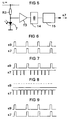
- the light emitting diodes with a pulsed operating voltage supplied, the z. B. by full-wave rectification is derived from the AC line voltage.
- this Context is of particular advantage in that also gives a characteristic light sensor signal whose Pulse frequency matches the mains frequency. The amplitude value this light sensor signal is a measure of the current luminous flux emitted by the LED matrix. The Signal frequency is a clear quantity that the Light source is switched on.
- the invention is also the functional state of the Monitor light sensor yourself. This tests the light sensor are carried out during switching breaks of the signal generator.
- test diode Around thereby producing no perceptible flashes of light these tests not by means of the LEDs, but under Using a test diode, the radiation in the invisible area and their partial radiation as well is detected by the light sensor.
- the test signal is also pulse-shaped, but of a pulse rate that is unique deviates from the mains frequency. This is clearly too distinguish whether the light sensor signal by the light emitting diodes or triggered by the test diode.
- the monitoring device including switching and evaluation device finally integrated into the signal generator, so that it too an easy exchange of the different light sources is possible.
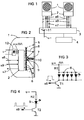
- Figure 1 is a light signal system in the form of a block diagram shown as an example with two signal transmitters 1.
- Each of these signal transmitters 1 is a signal transmitter control 2 assigned directly in the housing of the signal generator 1 is arranged. Via supply and control lines that Each of these signal generators is to be described in detail 1 or its signal generator control 2 with a Switching and evaluation device 3 connected. This is your turn connected to a device controller 4, which in known Way the operating states of the signal generator 1 accordingly controls a predetermined signal schedule.
- FIG. 2 illustrates the structure of the signal generator 1, its housing is covered on the front by a lens 5.
- This lens 5 is analogous to known lenses conventional signal transmitter designed so that here a detailed description is unnecessary.
- Inside the signal generator 1 is at a predetermined distance from this lens 5 and essentially parallel to it in a two-dimensional one Matrix a plurality of radiation-intensive light-emitting diodes arranged, hereinafter referred to as signal diodes 6 become. These form in their entirety and controlled together an extensive light source for the signal generator 1. This field of signal diodes is controlled together 6 through the already mentioned signal generator control 2, as will be explained.
- the immediate occurs Monitoring the radiation status of the signal diodes 6 by a light sensor 7, preferably as a photodiode is trained. You could easily use this light sensor 7 facing the signal diodes 6, for example on the inside arrange the lens 5. However, this is not necessary. It is more advantageous with regard to the arrangement and wiring the matrix of the signal diodes 6 and the Light sensor 7 also this as another element in the Arrange the level of the signal diodes 6. With this arrangement of the Light sensor 7 is exploited that part of the signal diodes 6 emitted light on the inside of the Diffuser is reflected and shines on the light sensor 7.
- a correspondingly amplified and weighted output signal the light sensor 7 is thus a measure of the current Signaling state of the signal generator 1 or its Signal diodes 6. This function of the light sensor is shown in FIG 7 by partial beams reflected on the lens 5 8 indicated schematically.
- This test diode 9 is chosen such that it is in the invisible range radiates, but their radiation is still in the range of sensitivity of the light sensor 7. Let these boundary conditions in combination with today's usual components of light sensor 7 and test diode 9 also quite realizable.
- the switching and evaluation device 3 controls Corresponding tests of the signal generator 1 are controlled by the switching and evaluation device 3. As schematically in Figure 1 indicated, this first has a switching relay 11, via the signal generator controls 2 AC mains voltage u ⁇ is fed. So it is possible in one by the Switching and evaluation device 3 found defective and the signaling state, which is hazardous to traffic 1 disconnect from the mains. Furthermore, the switching and Evaluation device 3 control signals s6 and s9. It serves the control signal s6 for switching the signal transmitter on or off 1, more precisely the signal diodes 6 and will follow referred to as signal control signal s6. The other of the Switching and evaluation device 3 the signaling controls 2 supplied control signal is used to switch the Test diode 9 and is therefore subsequently used as a test control signal designated s9.
- the signal generator controls 2 receives the Switching and evaluation device 3, on the other hand, a signal, the an output signal preprocessed in the signal generator controls 2 of the corresponding light sensors 7.
- These signals are now referred to as light sensor signals s7. As shown in FIG. 1, these signals can individually on separate lines between the switching and Evaluation device 3 and the signal generator controls 2 could be transmitted, alternatively this line multiple replaced by a serial transmission device become.
- the signal transmitters 1 is now the signal transmitter controls 2 assigned, each a full-wave rectifier 12 provided that the AC line voltage u ⁇ is supplied.
- the light sensor 7 is thus permanently prepared as long as AC mains voltage u ⁇ is present. That modulated by the received radiation Output signal of the light sensor 7 is via an amplifier stage 13 fed to a high-pass filter 14 and finally via a signal shaping stage 15 as a preprocessed light sensor signal s7 delivered to the switching and evaluation device 3.
- the function of the high-pass filter 14 should be pointed out here.
- the light sensor 7 not only receives light from the signal diodes or the test diode reflected by the lens 5, but also light from the environment entering through the lens 5, in particular a portion of daylight.
- this scattered light is to be understood as an interference.
- the intensity of this stray light incident from the outside in relation to the modulation frequency of the signal diodes 6 can be regarded as more or less uniform.
- This interference thus results in a direct current component of the output signal of the light sensor 7, which is eliminated by the high-pass filter 14.
- the dimensioning of this high-pass filter is therefore more problem-free the higher the modulation frequency of the signal diodes 6.
- an active filter stage for example implemented by Sample & Hold "circuits possible if it were necessary to take into account very short-term changes in a relatively radiation-intensive scattered light.
- the monitoring device described above for with Light emitting diodes equipped with signal transmitters now enable continuous or the signal transmitters at shorter intervals 1 to check that they are working properly. Checked are the two possible target states of a signal generator 1 in which it should be activated or deactivated.
- FIG. 6 the case is shown in the form of a pulse diagram in which the signal generator 1 is to be switched off (target state The actual state is now determined on the basis of the light sensor signal s7.
- FIG. 6 shows that the light sensor signal s7 in the example shown follows the course of the test control signal s9 directly with a slight delay determined by its operating parameters. This also applies in this case The frequency of the test control signal s9 should be at least a few Hz in order to be able to master the above-mentioned interference by radiated residual light well.
- the light sensor signal s7 directly reflects the test control signal s9 with a predetermined amplitude
- the result is as follows
- the actual state of the signal generator 1 agrees with the current target state and on the other hand it is also established that the light sensor 7 is functioning properly.
- the operating state of the monitored signal generator 1 is thus error-free.
- the target state of the signal generator is 1
- the test control signal s9 is generated and thus the test diode 9 is activated in a pulse-like manner.
- FIG. 8 is now in relation to the other target state
- One of the monitored signal transmitters 1 represents the normal case in which the target and actual states match.
- the test diode 9 is deactivated because the corresponding test control signal s9 is reset.
- the light control signal already shown in FIG. 7 is generated with the characteristic pulse shape.
- the test shows that the signal diodes 6 are working in accordance with the intended target state by comparing the amplitude of the light sensor signal s7 with a predetermined target amplitude, it is also possible to determine whether the monitored signal transmitter 1 has diminished in light.
- FIG. 9 illustrates the case in which the monitored signal generator 1 is in a target state A "is not switched on.
- the pulse forms for the test control signal s9 and the light sensor signal s7 already described with reference to FIG. 6 then occur again. This means that the monitored signal transmitter is switched off. The target and actual state do not match. The monitored signal transmitter 1 works incorrectly.
Abstract
Description
Claims (13)
- Lichtsignalanlage mit mindestens einem Signalgeber (1), dessen Lichtquelle durch in Form einer Matrix angeordnete Leuchtdioden (6) gebildet ist und mit einer Überwachungseinrichtung (2, 7, 9) zum Überprüfen der Leuchtdioden auf deren fehlerfreien Betriebszustand, dadurch gekennzeichnet, daß die Überwachungseinrichtung einen im Strahlengang der Leuchtdioden (6) angeordneten Lichtsensor (7) sowie eine mit diesem verbundene Auswerteeinrichtung (3) zum Vergleichen eines durch den Lichtsensor erzeugten Lichtsensorsignales (s7) mit einem vorgegebenen Sollwert aufweist, der einem normalen Betriebszustand der Leuchtdioden entspricht.
- Lichtsignalanlage nach Anspruch 1, wobei der Signalgeber (1) als transparente Abdeckung eine Streuscheibe (5) besitzt, dadurch gekennzeichnet, daß der Lichtsensor (7) in der Ebene der Leuchtdioden (6)angeordnet und wie diese auf die Streuscheibe ausgerichtet ist, wobei der Lichtsensor eine an der Streuscheibe reflektierte Teilstrahlung der Leuchtdioden empfängt.
- Lichtsignalanlage nach einem der Ansprüche 1 oder 2, dadurch gekennzeichnet, daß der in dem Signalgeber (1) angeordneten Matrix der Leuchtdioden (6) eine Signalgebersteuerung (2) unmittelbar zugeordnet ist, der als impulsförmige Betriebsspannung(u=) für die Leuchtdioden Netzwechselspannung (u∼), gleichgerichtet über eine Gleichrichteranordnung (12), zugeführt ist.
- Lichtsignalanlage nach Anspruch 3, dadurch gekennzeichnet, daß in der Signalgebersteuerung (2) eine an den Ausgang des Lichtsensors (7) angeschlossene Vorverarbeitungseinheit (13, 14, 15) zum Aufbereiten von dessen Ausgangssignal vorgesehen ist, die als aufbereitetes Signal das Lichtsensorsignal (s7) an die Auswerteeinrichtung (3) abgibt.
- Lichtsignalanlage nach Anspruch 4, dadurch gekennzeichnet, daß die Vorverarbeitungseinheit (13, 14, 15) einen an den Ausgang des Lichtsensors (7) angeschlossenen Vorverstärker (13) aufweist, der mit einem Hochpaßfilter (14) verbunden ist, an das als Ausgangsstufe eine Signalformerstufe (15) angeschlossen ist.
- Lichtsignalanlage nach einem der Ansprüche 1 bis 5, dadurch gekennzeichnet, daß in der Ebene der Leuchtdioden (6) eine Testdiode (9) angeordnet ist, deren emittierte Strahlung außerhalb des sichtbaren Spektralbereiches liegt und daß die spektrale Empfindlichkeit des Lichtsensors (7) dabei derart ausgebildet ist, daß er den Spektralbereich der Testdiode ebenso erfaßt wie den der sichtbares Licht emittierenden Leuchtdioden.
- Lichtsignalanlage nach Anspruch 6, dadurch gekennzeichnet, daß die Auswerteeinrichtung ferner als Schalteinrichtung ausgebildet ist und mit der Signalgebersteuerung (2) über Signalleitungen verbunden ist, über die Steuersignale (s6, s9) zum zeitlich gestaffelten Aktivieren der Leuchtdioden (6) bzw. der Testdiode (9) an die Signalgebersteuerung übertragen werden.
- Lichtsignalanlage nach Anspruch 7, dadurch gekennzeichnet, daß die Auswerteeinrichtung (3) Mittel zum Vergleichen der beiden Sollzustände (aus"/"ein") des Signalgebers (2) mit seinem durch den entsprechenden Zustand des Lichtsensorsignales (s7) definierten Istzustand aufweist.

- Lichtsignalanlage nach Anspruch 8, dadurch gekennzeichnet, daß die Auswerteeinrichtung (3) dabei Mittel zum Vergleichen der Amplitude des Lichtsensorsignales (s7) mit einem vorgegebenen, einem Nennwert der von den Leuchtdioden abgegebenen Strahlung entsprechenden Sollwert besitzt.
- Lichtsignalanlage nach einem der Ansprüche 1 bis 9, dadurch gekennzeichnet, daß die Auswerteeinrichtung (3) mit einer an sich konventionellen Gerätesteuerung (4) für einen bzw. mehrere Signalgeber (1) verbunden ist, wobei in dieser Gerätesteuerung Signalprogramme für den bzw. die angeschlossenen Signalgeber (1) abgelegt sind
- Verfahren zum Überwachen einer Lichtsignalanlage gemäß Anspruch 1, dadurch gekennzeichnet, daß den Leuchtdioden (6) im aktiven Signalzustand eine aus der Netzwechselspannung (u∼) gebildete pulsförmige Betriebsspannung (u=) zugeführt wird und daß das Ausgangssignal des Lichtsensors (7)vorverstärkt sowie durch einen Hochpaß gefiltert zu einem pulsförmigen Lichtsensorsignal (s7) vorverarbeitet wird, das im aktiven Signalzustand der Leuchtdioden entsprechend der Pulsfrequenz der pulsförmigen Betriebsspannung (u=) moduliert ist.
- Verfahren zum Überwachen einer Lichtsignalanlage nach Anspruch 11, dadurch gekennzeichnet, daß die pulsförmige Betriebsspannung (u=) durch Gleichrichten der Netzwechselspannung (u∼) gebildet wird und daß bei aktivierten Leuchtdioden (6) die Frequenz des pulsförmigen Lichtsensorsignals (s7) entsprechend der Frequenz der Netzwechselspannung (u∼) moduliert ist.
- Verfahren zum Überwachen einer Lichtsignalanlage nach einem der Ansprüche 11 oder 12, dadurch gekennzeichnet, daß das Lichtsensorsignal (s7) durch Vergleichen mit vorgegebenen Sollwerten in bezug auf seine Frequenz und seine Amplitude bewertet wird und daraus entsprechende Istzustände für den Schaltzustand der Leuchtdioden (6) bzw. für deren aktuell abgegebenen Lichtstrom abgeleitet werden, daß bei mangelnder Übereinstimmung von momentanem Soll- und Istzustand ein Fehlersignal erzeugt und an eine Gerätesteuerung (4) abgegeben wird, in der ein Signalprogramm für den bzw. die angeschlossenen Signalgeber (1) gespeichert ist, und daß diese daraufhin den bzw. die angeschlossenen Signalgeber (1) in einen definierten Fehlerzustand rücksetzt.
Applications Claiming Priority (2)
| Application Number | Priority Date | Filing Date | Title |
|---|---|---|---|
| DE19833209 | 1998-07-23 | ||
| DE19833209 | 1998-07-23 |
Publications (2)
| Publication Number | Publication Date |
|---|---|
| EP0974947A1 true EP0974947A1 (de) | 2000-01-26 |
| EP0974947B1 EP0974947B1 (de) | 2004-12-15 |
Family
ID=7875087
Family Applications (1)
| Application Number | Title | Priority Date | Filing Date |
|---|---|---|---|
| EP99113241A Expired - Lifetime EP0974947B1 (de) | 1998-07-23 | 1999-07-06 | Lichtsignalanlage sowie Verfahren zum Überwachen der Lichtsignalanlage |
Country Status (3)
| Country | Link |
|---|---|
| EP (1) | EP0974947B1 (de) |
| AT (1) | ATE285103T1 (de) |
| DE (1) | DE59911260D1 (de) |
Cited By (22)
| Publication number | Priority date | Publication date | Assignee | Title |
|---|---|---|---|---|
| FR2806512A1 (fr) * | 2000-03-15 | 2001-09-21 | Emmanuel Berque | Dispositif de signal pieton lumineux et sonore |
| WO2001078026A1 (en) * | 2000-04-11 | 2001-10-18 | System Sensor Division Of Pittway Corporation | Security device with bidirectional communication |
| FR2807911A1 (fr) * | 2000-04-14 | 2001-10-19 | Emmanuel Berque | Dispositif de detection de consommation electrique de signaux pietons lumineux |
| WO2002015145A2 (en) * | 2000-08-17 | 2002-02-21 | Power Signal Technologies, Inc. | Solid state light with self diagnostics and predictive failure analysis mechanisms |
| EP1215641A2 (de) * | 2000-12-13 | 2002-06-19 | Oy Sabik AB | Gerät zur Überwachung und zur Steuerung einer Strassenverkehrslichtsignalanlage |
| FR2818777A1 (fr) * | 2000-12-22 | 2002-06-28 | Giat Ind Sa | Dispositif de surveillance d'un ecran |
| GB2371689A (en) * | 2001-03-10 | 2002-07-31 | Siemens Plc | Modifying current waveform and detecting failure in non-incandescent lighting system |
| WO2002071812A2 (en) * | 2001-01-09 | 2002-09-12 | Gelcore Llc | Device to monitor a led traffic light |
| WO2003009647A1 (en) * | 2001-07-18 | 2003-01-30 | Power Signal Technologies, Inc. | Solid state traffic light with predictive failure analysis |
| DE10206649A1 (de) * | 2002-02-15 | 2003-08-28 | Garufo Gmbh | Anzeigevorrichtung |
| EP1562406A1 (de) * | 2004-02-03 | 2005-08-10 | Teknoware Oy | Verfahren und Vorrichtung zur Zustandsüberwachung von LEDs |
| EP1646267A1 (de) * | 2004-10-07 | 2006-04-12 | Siemens Schweiz AG | Verfahren zur Aktivierung von auf LED-Leuchtmitteln basierenden Signalen |
| WO2006067267A1 (en) * | 2004-12-23 | 2006-06-29 | Oy Sabik Ab | Led illuminator for traffic control |
| WO2007006684A1 (de) | 2005-07-13 | 2007-01-18 | Siemens Aktiengesellschaft | LICHTSIGNALANLAGE, INSBESONDERE FÜR DEN STRAßENVERKEHR |
| DE102009031808A1 (de) * | 2009-07-03 | 2011-03-10 | Lic Langmatz Gmbh | Anforderungsgerät für eine Verkehrsampel |
| ITUD20090184A1 (it) * | 2009-10-16 | 2011-04-17 | Solari Di Udine S P A | Dispositivo di segnalazione luminosa a led e relativo procedimento di controllo |
| CN102270367A (zh) * | 2010-06-04 | 2011-12-07 | 尤尼帕特铁路有限公司 | 用在固定警报或指示信号器中的光源 |
| EP2466566A1 (de) | 2009-01-23 | 2012-06-20 | Hella KGaA Hueck & Co. | Verfahren und Vorrichtung zum Steuern mindestens einer Lichtzeichenanlage eines Fußgängerüberwegs |
| EP2628652A1 (de) * | 2012-02-14 | 2013-08-21 | Siemens Schweiz AG | LED-Lichtquelle für ein Zwergsignal |
| DE102014119623A1 (de) * | 2014-12-23 | 2016-06-23 | Pintsch Bamag Antriebs- Und Verkehrstechnik Gmbh | LED-Lichtmodul, Signalleuchte mit einem solchen Lichtmodul sowie Verfahren zum Betreiben eines solchen Lichtmoduls |
| CN106473755A (zh) * | 2016-11-30 | 2017-03-08 | 江西科技师范大学 | 一种用于血糖监测的光声探测头 |
| EP3599595A1 (de) * | 2018-07-27 | 2020-01-29 | Siemens Mobility GmbH | Lichtsignalanlage mit schutz vor einem mastangriff |
Families Citing this family (1)
| Publication number | Priority date | Publication date | Assignee | Title |
|---|---|---|---|---|
| US8237590B2 (en) | 2008-04-28 | 2012-08-07 | GE Lighting Solutions, LLC | Apparatus and method for reducing failures in traffic signals |
Citations (4)
| Publication number | Priority date | Publication date | Assignee | Title |
|---|---|---|---|---|
| US4182977A (en) * | 1978-06-01 | 1980-01-08 | Trw Inc. | Constant output light emitting device |
| FR2586844A1 (fr) * | 1985-08-27 | 1987-03-06 | Sofrela Sa | Dispositif de signalisation utilisant des diodes electroluminescentes. |
| FR2634339A1 (fr) * | 1988-07-13 | 1990-01-19 | Guillot Francis | Lanterne de signalisation routiere auto-regulee |
| FR2672145A1 (fr) * | 1991-01-29 | 1992-07-31 | Electricite De France | Dispositif de detection d'un defaut d'une lampe d'un feu tricolore et installation de controle du trafic comportant un tel dispositif. |
-
1999
- 1999-07-06 DE DE59911260T patent/DE59911260D1/de not_active Expired - Fee Related
- 1999-07-06 AT AT99113241T patent/ATE285103T1/de not_active IP Right Cessation
- 1999-07-06 EP EP99113241A patent/EP0974947B1/de not_active Expired - Lifetime
Patent Citations (4)
| Publication number | Priority date | Publication date | Assignee | Title |
|---|---|---|---|---|
| US4182977A (en) * | 1978-06-01 | 1980-01-08 | Trw Inc. | Constant output light emitting device |
| FR2586844A1 (fr) * | 1985-08-27 | 1987-03-06 | Sofrela Sa | Dispositif de signalisation utilisant des diodes electroluminescentes. |
| FR2634339A1 (fr) * | 1988-07-13 | 1990-01-19 | Guillot Francis | Lanterne de signalisation routiere auto-regulee |
| FR2672145A1 (fr) * | 1991-01-29 | 1992-07-31 | Electricite De France | Dispositif de detection d'un defaut d'une lampe d'un feu tricolore et installation de controle du trafic comportant un tel dispositif. |
Cited By (33)
| Publication number | Priority date | Publication date | Assignee | Title |
|---|---|---|---|---|
| FR2806512A1 (fr) * | 2000-03-15 | 2001-09-21 | Emmanuel Berque | Dispositif de signal pieton lumineux et sonore |
| WO2001078026A1 (en) * | 2000-04-11 | 2001-10-18 | System Sensor Division Of Pittway Corporation | Security device with bidirectional communication |
| FR2807911A1 (fr) * | 2000-04-14 | 2001-10-19 | Emmanuel Berque | Dispositif de detection de consommation electrique de signaux pietons lumineux |
| US6448716B1 (en) | 2000-08-17 | 2002-09-10 | Power Signal Technologies, Inc. | Solid state light with self diagnostics and predictive failure analysis mechanisms |
| WO2002015145A2 (en) * | 2000-08-17 | 2002-02-21 | Power Signal Technologies, Inc. | Solid state light with self diagnostics and predictive failure analysis mechanisms |
| WO2002015145A3 (en) * | 2000-08-17 | 2003-01-16 | Power Signal Technologies Inc | Solid state light with self diagnostics and predictive failure analysis mechanisms |
| EP1215641A2 (de) * | 2000-12-13 | 2002-06-19 | Oy Sabik AB | Gerät zur Überwachung und zur Steuerung einer Strassenverkehrslichtsignalanlage |
| EP1215641A3 (de) * | 2000-12-13 | 2004-12-15 | Oy Sabik AB | Gerät zur Überwachung und zur Steuerung einer Strassenverkehrslichtsignalanlage |
| WO2002052525A1 (fr) * | 2000-12-22 | 2002-07-04 | Giat Industries | Dispositif de surveillance d'un ecran |
| FR2818777A1 (fr) * | 2000-12-22 | 2002-06-28 | Giat Ind Sa | Dispositif de surveillance d'un ecran |
| WO2002071812A2 (en) * | 2001-01-09 | 2002-09-12 | Gelcore Llc | Device to monitor a led traffic light |
| WO2002071812A3 (en) * | 2001-01-10 | 2003-01-03 | Gelcore Llc | Device to monitor a led traffic light |
| GB2371689A (en) * | 2001-03-10 | 2002-07-31 | Siemens Plc | Modifying current waveform and detecting failure in non-incandescent lighting system |
| GB2371689B (en) * | 2001-03-10 | 2003-07-16 | Siemens Plc | Electrical apparatus and method |
| WO2003009647A1 (en) * | 2001-07-18 | 2003-01-30 | Power Signal Technologies, Inc. | Solid state traffic light with predictive failure analysis |
| DE10206649A1 (de) * | 2002-02-15 | 2003-08-28 | Garufo Gmbh | Anzeigevorrichtung |
| EP1562406A1 (de) * | 2004-02-03 | 2005-08-10 | Teknoware Oy | Verfahren und Vorrichtung zur Zustandsüberwachung von LEDs |
| EP1646267A1 (de) * | 2004-10-07 | 2006-04-12 | Siemens Schweiz AG | Verfahren zur Aktivierung von auf LED-Leuchtmitteln basierenden Signalen |
| WO2006067267A1 (en) * | 2004-12-23 | 2006-06-29 | Oy Sabik Ab | Led illuminator for traffic control |
| WO2007006684A1 (de) | 2005-07-13 | 2007-01-18 | Siemens Aktiengesellschaft | LICHTSIGNALANLAGE, INSBESONDERE FÜR DEN STRAßENVERKEHR |
| DE102005032719A1 (de) * | 2005-07-13 | 2007-01-25 | Siemens Ag | Lichtsignalanlage, insbesondere für den Straßenverkehr |
| EP2466566A1 (de) | 2009-01-23 | 2012-06-20 | Hella KGaA Hueck & Co. | Verfahren und Vorrichtung zum Steuern mindestens einer Lichtzeichenanlage eines Fußgängerüberwegs |
| DE102009031808B4 (de) * | 2009-07-03 | 2012-04-19 | Langmatz Gmbh | Anforderungsgerät für eine Verkehrsampel |
| DE102009031808A1 (de) * | 2009-07-03 | 2011-03-10 | Lic Langmatz Gmbh | Anforderungsgerät für eine Verkehrsampel |
| WO2011045663A1 (en) * | 2009-10-16 | 2011-04-21 | Solari Di Udine Spa | Led-type luminous signaling device and relative control method |
| ITUD20090184A1 (it) * | 2009-10-16 | 2011-04-17 | Solari Di Udine S P A | Dispositivo di segnalazione luminosa a led e relativo procedimento di controllo |
| CN102270367A (zh) * | 2010-06-04 | 2011-12-07 | 尤尼帕特铁路有限公司 | 用在固定警报或指示信号器中的光源 |
| EP2628652A1 (de) * | 2012-02-14 | 2013-08-21 | Siemens Schweiz AG | LED-Lichtquelle für ein Zwergsignal |
| DE102014119623A1 (de) * | 2014-12-23 | 2016-06-23 | Pintsch Bamag Antriebs- Und Verkehrstechnik Gmbh | LED-Lichtmodul, Signalleuchte mit einem solchen Lichtmodul sowie Verfahren zum Betreiben eines solchen Lichtmoduls |
| EP3038433A2 (de) | 2014-12-23 | 2016-06-29 | PINTSCH BAMAG Antriebs- und Verkehrstechnik GmbH | Led-lichtmodul, signalleuchte mit einem solchen lichtmodul sowie verfahren zum betreiben eines solchen lichtmoduls |
| EP3038433A3 (de) * | 2014-12-23 | 2016-07-27 | PINTSCH BAMAG Antriebs- und Verkehrstechnik GmbH | Led-lichtmodul, signalleuchte mit einem solchen lichtmodul sowie verfahren zum betreiben eines solchen lichtmoduls |
| CN106473755A (zh) * | 2016-11-30 | 2017-03-08 | 江西科技师范大学 | 一种用于血糖监测的光声探测头 |
| EP3599595A1 (de) * | 2018-07-27 | 2020-01-29 | Siemens Mobility GmbH | Lichtsignalanlage mit schutz vor einem mastangriff |
Also Published As
| Publication number | Publication date |
|---|---|
| ATE285103T1 (de) | 2005-01-15 |
| EP0974947B1 (de) | 2004-12-15 |
| DE59911260D1 (de) | 2005-01-20 |
Similar Documents
| Publication | Publication Date | Title |
|---|---|---|
| EP0974947B1 (de) | Lichtsignalanlage sowie Verfahren zum Überwachen der Lichtsignalanlage | |
| WO2011086027A1 (de) | Lichtsignal | |
| EP1992542B2 (de) | LED-Anordnung für Lichtsignalgeber für Bahnübergänge, Lichtsignalgeber für Bahnübergänge mit einer solchen LED-Anordnung sowie Verfahren zum Betreiben der LED-Anordnung | |
| EP0802081B1 (de) | Rückleuchte eines Fahrzeuges, vorzugsweise eines Kraftfahrzeuges | |
| DE102009060791A1 (de) | Lichtmodul für eine Beleuchtungseinrichtung eines Kraftfahrzeugs sowie Beleuchtungseinrichtung eines Kraftfahrzeugs mit einem solchen Lichtmodul | |
| EP2877114A1 (de) | Verfahren zur verbesserung der ausleuchtung eines ausleuchtbereichs | |
| DE602005005095T2 (de) | Verfahren und Vorrichtung zur Zustandsüberwachung von LEDs | |
| WO2014095176A1 (de) | Verfahren und einrichtung zur funktionsprüfung von leuchtmitteln | |
| DE102008034524B4 (de) | Notlichteinheit | |
| EP2050619B1 (de) | Vorrichtung und Verfahren zum Ermitteln eines Betriebsparameters von zumindest einem Leuchtmittel einer Lichtquelle eines Kraftfahrzeuges | |
| DE102006056148B4 (de) | Verfahren zur Funktionsüberwachung einer Lichtsignalanlage und Verkehrssteuerungs-Lichtsignalanlage | |
| DE60117683T2 (de) | Gerät zur Überwachung und zur Steuerung einer Strassenverkehrslichtsignalanlage | |
| WO2007036509A1 (de) | Verfahren und einrichtung zur überwachung des lichtsignals eines elektro-optischen leuchtelements, insbesondere einer im bahnbetrieb verwendeten hochstrom-led eines sicheren bahnsignals | |
| EP2584874B1 (de) | LED-Leuchte mit Überwachung | |
| DE102017213992B4 (de) | Verfahren zum Betreiben einer Innenraumbeleuchtungsvorrichtung, Innenraumbeleuchtungsvorrichtung und Kraftfahrzeug mit einer Innenraumbeleuchtungsvorrichtung | |
| DE10214198B4 (de) | Schaltbares Leuchtmittel mit automatischer Notbeleuchtung | |
| EP3243363B1 (de) | Lichtsystem mit anwesenheitserkennung von personen, unter verwendung von licht mit unterschiedlichem spektrum | |
| EP3518628A1 (de) | Helligkeitssensor auf led-modul | |
| WO2003061347A1 (de) | Signalgeberleuchte mit leuchtdioden | |
| DE10208462A1 (de) | Beleuchtungsanordnung | |
| EP3038433B1 (de) | Led-lichtmodul, signalleuchte mit einem solchen lichtmodul sowie verfahren zum betreiben eines solchen lichtmoduls | |
| EP2201824B1 (de) | Schnittstelle für leuchtmittel -betriebsgerät | |
| DE102007053793A1 (de) | Leuchtmittel-Betriebsgerät mit Schnittstelle | |
| DE202008006297U1 (de) | LED Anordnung für Lichtsignalgeber insbesondere für Bahnübergänge sowie Lichtsignalgeber insbesondere für Bahnübergänge mit einer solchen LED-Anordnung | |
| WO2021259535A1 (de) | System zur erkennung einer orientierung eines lichtsensors |
Legal Events
| Date | Code | Title | Description |
|---|---|---|---|
| PUAI | Public reference made under article 153(3) epc to a published international application that has entered the european phase |
Free format text: ORIGINAL CODE: 0009012 |
|
| AK | Designated contracting states |
Kind code of ref document: A1 Designated state(s): AT CH DE LI NL |
|
| AX | Request for extension of the european patent |
Free format text: AL;LT;LV;MK;RO;SI |
|
| 17P | Request for examination filed |
Effective date: 20000303 |
|
| AKX | Designation fees paid |
Free format text: AT CH DE LI NL |
|
| 17Q | First examination report despatched |
Effective date: 20040202 |
|
| GRAP | Despatch of communication of intention to grant a patent |
Free format text: ORIGINAL CODE: EPIDOSNIGR1 |
|
| GRAS | Grant fee paid |
Free format text: ORIGINAL CODE: EPIDOSNIGR3 |
|
| GRAA | (expected) grant |
Free format text: ORIGINAL CODE: 0009210 |
|
| AK | Designated contracting states |
Kind code of ref document: B1 Designated state(s): AT CH DE LI NL |
|
| REG | Reference to a national code |
Ref country code: CH Ref legal event code: EP |
|
| REG | Reference to a national code |
Ref country code: CH Ref legal event code: NV Representative=s name: SIEMENS SCHWEIZ AG |
|
| REF | Corresponds to: |
Ref document number: 59911260 Country of ref document: DE Date of ref document: 20050120 Kind code of ref document: P |
|
| PLBI | Opposition filed |
Free format text: ORIGINAL CODE: 0009260 |
|
| 26 | Opposition filed |
Opponent name: SIGNALBAU HUBER GMBH Effective date: 20050719 |
|
| PLAX | Notice of opposition and request to file observation + time limit sent |
Free format text: ORIGINAL CODE: EPIDOSNOBS2 |
|
| NLR1 | Nl: opposition has been filed with the epo |
Opponent name: SIGNALBAU HUBER GMBH |
|
| PLBB | Reply of patent proprietor to notice(s) of opposition received |
Free format text: ORIGINAL CODE: EPIDOSNOBS3 |
|
| PLCK | Communication despatched that opposition was rejected |
Free format text: ORIGINAL CODE: EPIDOSNREJ1 |
|
| PLBN | Opposition rejected |
Free format text: ORIGINAL CODE: 0009273 |
|
| STAA | Information on the status of an ep patent application or granted ep patent |
Free format text: STATUS: OPPOSITION REJECTED |
|
| 27O | Opposition rejected |
Effective date: 20071223 |
|
| NLR2 | Nl: decision of opposition |
Effective date: 20071223 |
|
| PGFP | Annual fee paid to national office [announced via postgrant information from national office to epo] |
Ref country code: DE Payment date: 20080919 Year of fee payment: 10 |
|
| PGFP | Annual fee paid to national office [announced via postgrant information from national office to epo] |
Ref country code: NL Payment date: 20080707 Year of fee payment: 10 Ref country code: AT Payment date: 20080613 Year of fee payment: 10 |
|
| PGFP | Annual fee paid to national office [announced via postgrant information from national office to epo] |
Ref country code: CH Payment date: 20081016 Year of fee payment: 10 |
|
| REG | Reference to a national code |
Ref country code: CH Ref legal event code: PCAR Free format text: SIEMENS SCHWEIZ AG;INTELLECTUAL PROPERTY FREILAGERSTRASSE 40;8047 ZUERICH (CH) |
|
| REG | Reference to a national code |
Ref country code: CH Ref legal event code: PL |
|
| NLV4 | Nl: lapsed or anulled due to non-payment of the annual fee |
Effective date: 20100201 |
|
| PG25 | Lapsed in a contracting state [announced via postgrant information from national office to epo] |
Ref country code: LI Free format text: LAPSE BECAUSE OF NON-PAYMENT OF DUE FEES Effective date: 20090731 Ref country code: CH Free format text: LAPSE BECAUSE OF NON-PAYMENT OF DUE FEES Effective date: 20090731 |
|
| PG25 | Lapsed in a contracting state [announced via postgrant information from national office to epo] |
Ref country code: DE Free format text: LAPSE BECAUSE OF NON-PAYMENT OF DUE FEES Effective date: 20100202 Ref country code: AT Free format text: LAPSE BECAUSE OF NON-PAYMENT OF DUE FEES Effective date: 20090706 |
|
| PG25 | Lapsed in a contracting state [announced via postgrant information from national office to epo] |
Ref country code: NL Free format text: LAPSE BECAUSE OF NON-PAYMENT OF DUE FEES Effective date: 20100201 |