EP0974947A1 - Traffic light apparatus and method to monitor the traffic light apparatus - Google Patents
Traffic light apparatus and method to monitor the traffic light apparatus Download PDFInfo
- Publication number
- EP0974947A1 EP0974947A1 EP99113241A EP99113241A EP0974947A1 EP 0974947 A1 EP0974947 A1 EP 0974947A1 EP 99113241 A EP99113241 A EP 99113241A EP 99113241 A EP99113241 A EP 99113241A EP 0974947 A1 EP0974947 A1 EP 0974947A1
- Authority
- EP
- European Patent Office
- Prior art keywords
- light
- signal
- emitting diodes
- light sensor
- voltage
- Prior art date
- Legal status (The legal status is an assumption and is not a legal conclusion. Google has not performed a legal analysis and makes no representation as to the accuracy of the status listed.)
- Granted
Links
Images
Classifications
-
- G—PHYSICS
- G08—SIGNALLING
- G08G—TRAFFIC CONTROL SYSTEMS
- G08G1/00—Traffic control systems for road vehicles
- G08G1/09—Arrangements for giving variable traffic instructions
- G08G1/095—Traffic lights
-
- G—PHYSICS
- G08—SIGNALLING
- G08G—TRAFFIC CONTROL SYSTEMS
- G08G1/00—Traffic control systems for road vehicles
- G08G1/097—Supervising of traffic control systems, e.g. by giving an alarm if two crossing streets have green light simultaneously
-
- H—ELECTRICITY
- H05—ELECTRIC TECHNIQUES NOT OTHERWISE PROVIDED FOR
- H05B—ELECTRIC HEATING; ELECTRIC LIGHT SOURCES NOT OTHERWISE PROVIDED FOR; CIRCUIT ARRANGEMENTS FOR ELECTRIC LIGHT SOURCES, IN GENERAL
- H05B45/00—Circuit arrangements for operating light-emitting diodes [LED]
- H05B45/50—Circuit arrangements for operating light-emitting diodes [LED] responsive to malfunctions or undesirable behaviour of LEDs; responsive to LED life; Protective circuits
- H05B45/58—Circuit arrangements for operating light-emitting diodes [LED] responsive to malfunctions or undesirable behaviour of LEDs; responsive to LED life; Protective circuits involving end of life detection of LEDs
-
- H—ELECTRICITY
- H05—ELECTRIC TECHNIQUES NOT OTHERWISE PROVIDED FOR
- H05B—ELECTRIC HEATING; ELECTRIC LIGHT SOURCES NOT OTHERWISE PROVIDED FOR; CIRCUIT ARRANGEMENTS FOR ELECTRIC LIGHT SOURCES, IN GENERAL
- H05B47/00—Circuit arrangements for operating light sources in general, i.e. where the type of light source is not relevant
- H05B47/20—Responsive to malfunctions or to light source life; for protection
Definitions
- the invention relates to a light signal system according to the preamble of claim 1 and a method to monitor this traffic light system.
- a traffic signal generator is also known, in which on a printed circuit board LEDs as a light source are arranged in a configuration that matches the pattern a traffic sign.
- LEDs are related to deviations from the nominal voltage, i.e. with voltage drops far more sensitive than incandescent lamps. According to the known solution a significant loss of light at a level below the nominal voltage lying operating voltage avoided in that the LEDs in individual, connected in series to each other Chains are arranged, the light emitting diode chains are.
- the present invention is therefore based on the object a light signal system of the type mentioned with a To create monitoring device based on the properties of the light emitting diodes used as the light source and a corresponding method for monitoring the traffic light system.
- the first subtask is the light signal system type mentioned in the characterizing part of the claim 1 described features solved.
- the solution to the others Partial task is characterized by the claim 1 dependent method claim described.
- the light emitting diodes with a pulsed operating voltage supplied, the z. B. by full-wave rectification is derived from the AC line voltage.
- this Context is of particular advantage in that also gives a characteristic light sensor signal whose Pulse frequency matches the mains frequency. The amplitude value this light sensor signal is a measure of the current luminous flux emitted by the LED matrix. The Signal frequency is a clear quantity that the Light source is switched on.
- the invention is also the functional state of the Monitor light sensor yourself. This tests the light sensor are carried out during switching breaks of the signal generator.
- test diode Around thereby producing no perceptible flashes of light these tests not by means of the LEDs, but under Using a test diode, the radiation in the invisible area and their partial radiation as well is detected by the light sensor.
- the test signal is also pulse-shaped, but of a pulse rate that is unique deviates from the mains frequency. This is clearly too distinguish whether the light sensor signal by the light emitting diodes or triggered by the test diode.
- the monitoring device including switching and evaluation device finally integrated into the signal generator, so that it too an easy exchange of the different light sources is possible.
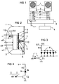
- Figure 1 is a light signal system in the form of a block diagram shown as an example with two signal transmitters 1.
- Each of these signal transmitters 1 is a signal transmitter control 2 assigned directly in the housing of the signal generator 1 is arranged. Via supply and control lines that Each of these signal generators is to be described in detail 1 or its signal generator control 2 with a Switching and evaluation device 3 connected. This is your turn connected to a device controller 4, which in known Way the operating states of the signal generator 1 accordingly controls a predetermined signal schedule.
- FIG. 2 illustrates the structure of the signal generator 1, its housing is covered on the front by a lens 5.
- This lens 5 is analogous to known lenses conventional signal transmitter designed so that here a detailed description is unnecessary.
- Inside the signal generator 1 is at a predetermined distance from this lens 5 and essentially parallel to it in a two-dimensional one Matrix a plurality of radiation-intensive light-emitting diodes arranged, hereinafter referred to as signal diodes 6 become. These form in their entirety and controlled together an extensive light source for the signal generator 1. This field of signal diodes is controlled together 6 through the already mentioned signal generator control 2, as will be explained.
- the immediate occurs Monitoring the radiation status of the signal diodes 6 by a light sensor 7, preferably as a photodiode is trained. You could easily use this light sensor 7 facing the signal diodes 6, for example on the inside arrange the lens 5. However, this is not necessary. It is more advantageous with regard to the arrangement and wiring the matrix of the signal diodes 6 and the Light sensor 7 also this as another element in the Arrange the level of the signal diodes 6. With this arrangement of the Light sensor 7 is exploited that part of the signal diodes 6 emitted light on the inside of the Diffuser is reflected and shines on the light sensor 7.
- a correspondingly amplified and weighted output signal the light sensor 7 is thus a measure of the current Signaling state of the signal generator 1 or its Signal diodes 6. This function of the light sensor is shown in FIG 7 by partial beams reflected on the lens 5 8 indicated schematically.
- This test diode 9 is chosen such that it is in the invisible range radiates, but their radiation is still in the range of sensitivity of the light sensor 7. Let these boundary conditions in combination with today's usual components of light sensor 7 and test diode 9 also quite realizable.
- the switching and evaluation device 3 controls Corresponding tests of the signal generator 1 are controlled by the switching and evaluation device 3. As schematically in Figure 1 indicated, this first has a switching relay 11, via the signal generator controls 2 AC mains voltage u ⁇ is fed. So it is possible in one by the Switching and evaluation device 3 found defective and the signaling state, which is hazardous to traffic 1 disconnect from the mains. Furthermore, the switching and Evaluation device 3 control signals s6 and s9. It serves the control signal s6 for switching the signal transmitter on or off 1, more precisely the signal diodes 6 and will follow referred to as signal control signal s6. The other of the Switching and evaluation device 3 the signaling controls 2 supplied control signal is used to switch the Test diode 9 and is therefore subsequently used as a test control signal designated s9.
- the signal generator controls 2 receives the Switching and evaluation device 3, on the other hand, a signal, the an output signal preprocessed in the signal generator controls 2 of the corresponding light sensors 7.
- These signals are now referred to as light sensor signals s7. As shown in FIG. 1, these signals can individually on separate lines between the switching and Evaluation device 3 and the signal generator controls 2 could be transmitted, alternatively this line multiple replaced by a serial transmission device become.
- the signal transmitters 1 is now the signal transmitter controls 2 assigned, each a full-wave rectifier 12 provided that the AC line voltage u ⁇ is supplied.
- the light sensor 7 is thus permanently prepared as long as AC mains voltage u ⁇ is present. That modulated by the received radiation Output signal of the light sensor 7 is via an amplifier stage 13 fed to a high-pass filter 14 and finally via a signal shaping stage 15 as a preprocessed light sensor signal s7 delivered to the switching and evaluation device 3.
- the function of the high-pass filter 14 should be pointed out here.
- the light sensor 7 not only receives light from the signal diodes or the test diode reflected by the lens 5, but also light from the environment entering through the lens 5, in particular a portion of daylight.
- this scattered light is to be understood as an interference.
- the intensity of this stray light incident from the outside in relation to the modulation frequency of the signal diodes 6 can be regarded as more or less uniform.
- This interference thus results in a direct current component of the output signal of the light sensor 7, which is eliminated by the high-pass filter 14.
- the dimensioning of this high-pass filter is therefore more problem-free the higher the modulation frequency of the signal diodes 6.
- an active filter stage for example implemented by Sample & Hold "circuits possible if it were necessary to take into account very short-term changes in a relatively radiation-intensive scattered light.
- the monitoring device described above for with Light emitting diodes equipped with signal transmitters now enable continuous or the signal transmitters at shorter intervals 1 to check that they are working properly. Checked are the two possible target states of a signal generator 1 in which it should be activated or deactivated.
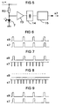
- FIG. 6 the case is shown in the form of a pulse diagram in which the signal generator 1 is to be switched off (target state The actual state is now determined on the basis of the light sensor signal s7.
- FIG. 6 shows that the light sensor signal s7 in the example shown follows the course of the test control signal s9 directly with a slight delay determined by its operating parameters. This also applies in this case The frequency of the test control signal s9 should be at least a few Hz in order to be able to master the above-mentioned interference by radiated residual light well.
- the light sensor signal s7 directly reflects the test control signal s9 with a predetermined amplitude
- the result is as follows
- the actual state of the signal generator 1 agrees with the current target state and on the other hand it is also established that the light sensor 7 is functioning properly.
- the operating state of the monitored signal generator 1 is thus error-free.
- the target state of the signal generator is 1
- the test control signal s9 is generated and thus the test diode 9 is activated in a pulse-like manner.
- FIG. 8 is now in relation to the other target state
- One of the monitored signal transmitters 1 represents the normal case in which the target and actual states match.
- the test diode 9 is deactivated because the corresponding test control signal s9 is reset.
- the light control signal already shown in FIG. 7 is generated with the characteristic pulse shape.
- the test shows that the signal diodes 6 are working in accordance with the intended target state by comparing the amplitude of the light sensor signal s7 with a predetermined target amplitude, it is also possible to determine whether the monitored signal transmitter 1 has diminished in light.
- FIG. 9 illustrates the case in which the monitored signal generator 1 is in a target state A "is not switched on.
- the pulse forms for the test control signal s9 and the light sensor signal s7 already described with reference to FIG. 6 then occur again. This means that the monitored signal transmitter is switched off. The target and actual state do not match. The monitored signal transmitter 1 works incorrectly.
Abstract
Description
Die Erfindung bezieht sich auf eine Lichtsignalanlage gemäß dem Oberbegriff des Patentanspruches 1 sowie auf ein Verfahren zum Überwachen dieser Lichtsignalanlage.The invention relates to a light signal system according to the preamble of claim 1 and a method to monitor this traffic light system.
Fortschritte in der Halbleitertechnologie haben unter anderem zu immer lichtintensiveren Leuchtdioden geführt, die sich für eine Vielzahl von Anwendungsmöglichkeiten eignen. So sind auch Anwendungen dieser Bauelemente als Lichtquellen für Signalgeber bekannt geworden. Beispielsweise ist aus US-A-4 954 822 eine Straßenverkehrsampel bekannt, bei der sehr lichtintensive Leuchtdioden auf einem Träger in einem geometrischen Muster angeordnet sind, das ein Verkehrszeichen, beispielsweise für einen Fußgängerübergang wiedergibt. Die Leuchtdioden werden durch eine Betriebsspannung versorgt, die mittels eines Vollweggleichrichters aus einer üblichen Netzwechselspannung abgeleitet und auf die Nennspannung der Bauelemente herunter transformiert wird. Beschrieben sind auch Möglichkeiten eines Betriebes mit herabgesetztem Lichtstrom, beispielsweise indem eine Halbwelle der Netzwechselspannung unterdrückt und damit der dem Gleichrichter entnommene Strom reduziert wird. Ob dies sinnvoll ist, sei dahingestellt. Wesentlicher ist jedenfalls der beschriebene Vorteil, daß Leuchtdioden bei sachgemäßer Ansteuerung langlebig sind und ein damit ausgestatteter Signalgeber eine wesentlich geringere elektrische Leistung erfordert als ein vergleichbarer, konventionell mit einer Glühlampe bestückter Signalgeber. Die bekannte Lösung offenbart keine spezifischen Maßnahmen zur Überwachung des Signalgebers auf einen fehlerfreien Betrieb.Advances in semiconductor technology have among other things led to ever more light-intensive LEDs that are suitable for a variety of applications. So are also uses these components as light sources for signal transmitters known. For example, from US-A-4,954 822 known a traffic light, in the very light-intensive Light emitting diodes on a support in a geometric Patterns are arranged that represent a traffic sign, for example for a pedestrian crossing. The light emitting diodes are supplied by an operating voltage, which means a full-wave rectifier from a normal AC line voltage derived and based on the nominal voltage of the components is transformed down. Possibilities are also described an operation with reduced luminous flux, for example by suppressing a half-wave of the AC mains voltage and thus the current drawn from the rectifier is reduced. It remains to be seen whether this makes sense. More essential is the described advantage in any case that When properly controlled, LEDs are durable and a signal generator equipped with it a much lower one electrical power requires as a comparable, Conventionally equipped with a light bulb. The known solution does not disclose any specific measures for Monitoring of the signal generator for correct operation.
Aus US-A-5 663 719 ist ferner ein Verkehrssignalgeber bekannt, bei dem auf einer Leiterplatte Leuchtdioden als Lichtquelle in einer Konfiguration angeordnet sind, die das Muster eines Verkehrszeichens wiedergibt. Bei dieser bekannten Lösung ist unter anderem auf die Möglichkeit abgestellt, in konventionell bestückten Signalgebern die Glühlampen bei einfachem Austausch durch Leuchtdioden zu ersetzen. Dabei können Nachteile auftreten. Leuchtdioden sind in bezug auf Abweichungen von der Nennspannung, d.h. bei Spannungsabfällen weit empfindlicher als Glühlampen. Nach der bekannten Lösung wird ein erheblicher Lichtverlust bei einer unterhalb der Nennspannung liegenden Betriebsspannung dadurch vermieden, daß die Leuchtdioden in einzelnen, zueinander in Serie geschalteten Ketten angeordnet sind, wobei die Leuchtdiodenketten sind. Ferner ist vorgesehen, die einzelnen Ketten durch Schalter überbrücken zu können. Im Falle von zu niedriger Netzspannung werden einzelne Leuchtdiodenketten abgeschaltet. Dies hat zur Folge, daß die eingeschalteten Leuchtdioden auch bei unterschiedlichen Netzspannungen immer annähernd mit ihrer Nennspannung, also mit hoher Lichtausbeute betrieben werden. Bei Spannungsabfällen reduziert sich dann zwar die Zahl der tatsächlich betriebenen Leuchtdioden, der dadurch eintretende Lichtverlust ist jedoch geringer als dann, wenn zwar alle Leuchtdioden, jedoch mit entsprechend geringerer Spannung betrieben würden. Insoweit ist bei der bekannten Lösung eine gewisse Überwachung der Signalgeber auf vom Nennbetrieb abweichende Betriebszustände vorgesehen, genau genommen betrifft dies jedoch noch keine Überwachung des Signalgebers auf Fehlfunktionen.From US-A-5 663 719 a traffic signal generator is also known, in which on a printed circuit board LEDs as a light source are arranged in a configuration that matches the pattern a traffic sign. With this known solution is geared towards the possibility, among other things, of conventionally equipped signal transmitters the light bulbs with simple Exchange to be replaced by LEDs. You can Disadvantages occur. LEDs are related to deviations from the nominal voltage, i.e. with voltage drops far more sensitive than incandescent lamps. According to the known solution a significant loss of light at a level below the nominal voltage lying operating voltage avoided in that the LEDs in individual, connected in series to each other Chains are arranged, the light emitting diode chains are. It is also provided that the individual chains through To be able to bridge switches. In case of too low Mains voltage is switched off individual LED chains. This has the consequence that the light-emitting diodes are also switched on with different mains voltages always approximately with yours Nominal voltage, i.e. operated with high luminous efficacy. In the case of voltage drops, the number is reduced of the actually operated LEDs, the one that enters Loss of light, however, is less than if all LEDs, but with a correspondingly lower voltage would be operated. So far is with the known solution a certain monitoring of the signal generator for nominal operation deviating operating states are provided, strictly concerns however, this does not yet monitor the signal generator for malfunctions.
Eine wenigstens periodische Überwachung von Signalgebern von
Lichtsignalanlagen, ist aber zumindestens dann in vielen Ländem
zwingende Vorschrift, wenn die Lichtsignalanlagen im öffentlichen
Bereich zur Verkehrsregelung eingesetzt werden.
Dabei sind die individuellen Funktionen der Signalgeber zu
berücksichtigen. So hat z. B. ein fälschlich leuchtendes
![]()
![]()
Es genügt also nicht, Lichtsignalanlagen nur daraufhin zu überwachen, daß die Signalgeber hinreichend gut erkennbar sind, d. h. wie bei obengenannter Lösung, die Lichtstärke des Signalgebers nachgeregelt wird, um Alterungserscheinungen, Netzspannungsschwankungen oder Leitungsverluste zu kompensieren. Vorschrift sind in vielen Ländern periodisch durchgeführte Überwachungen der Signalgeber, um möglichst unmittelbar jede Fehlfunktion, d. h. insbesondere auch die mangelnde Übereinstimmung des Istzustandes jedes Signalgebers mit seinem nach einem Signalprogramm vorgegebenen momentanen Sollzustand festzustellen und daraufhin die Lichtsignalanlage in einen Notbetriebszustand rückzusetzen.So it is not enough to only shut down traffic lights monitor that the signal generator is sufficiently well recognizable are, d. H. as with the above solution, the light intensity of the Signal generator is readjusted to prevent signs of aging, Compensate for line voltage fluctuations or line losses. Regulation are carried out periodically in many countries Monitoring of the signal generator in order to be as immediate as possible any malfunction, d. H. especially the lack Correspondence between the actual state of each signal generator and its according to a signal program predefined current target state determine and then the traffic light system in reset an emergency operating state.
Bei konventionell mit Glühlampen bestückten Signalgebern werden derartige Fehlfunktionen durch Strom- und Spannungsmessung an der Lichtquelle bzw. ihren Zuleitungen festgestellt. Die bekannten Maßnahmen und Schaltungen sind aber bei mit Leuchtdioden bestückten Signalgebern nur bedingt tauglich. Wie bereits erwähnt, ist bei Leuchtdioden die Charakteristik von Lichtstrom zur Betriebsspannung wesentlich kritischer als bei einer Glühlampe. Andererseits ist der Stromverbrauch bei einem Signalgeber, bestückt mit heute bereits verfügbaren Leuchtdioden, um Größenordnungen niedriger als beim Einsatz einer Glühlampe. Einfache Anpassungen bekannter Schaltungsmaßnahmen zum Überwachen von Signalgebern sind daher als kritisch, als strengen Sicherheitsvorschriften häufig nicht mehr genügend einzustufen. Dennoch stellt sich das Problem, die Voraussetzungen dafür zu schaffen, bei einem Ersatz der Glühlampe mit möglichst wenig Wartungsaufwand statt dessen Leuchtdioden als Lichtqelle einsetzen zu können. Dieses Problem wird zwar wenigstens bei einem Teil des genannten Standes der Technik angesprochen, jedoch im Hinblick auf kritische Fehltunktionen nicht gelöst.In the case of signal generators conventionally equipped with incandescent lamps such malfunctions due to current and voltage measurement detected on the light source or its leads. The known measures and circuits are with LEDs equipped with signal transmitters are only of limited suitability. As already mentioned, the characteristic of LEDs is from luminous flux to operating voltage much more critical than with a light bulb. On the other hand, the power consumption is a signal generator equipped with those already available today LEDs, orders of magnitude lower than when used a light bulb. Simple adjustments to known circuit measures to monitor signaling devices are therefore critical, often no longer as strict safety regulations enough to classify. Still, the problem arises that To create the conditions for this when replacing the light bulb with as little maintenance as possible instead To be able to use LEDs as a light source. This problem will be at least in part of the stand the technology, but with regard to critical Malfunctions not resolved.
Der vorliegenden Erfindung liegt daher die Aufgabe zugrunde, eine Lichtsignalanlage der eingangs genannten Art mit einer Überwachungseinrichtung zu schaffen, die auf die Eigenschaften der als Lichtquelle eingesetzten Leuchtdioden exakt abgestimmt ist sowie ein entsprechendes Verfahren zum Überwachen der Lichtsignalanlage anzugeben.The present invention is therefore based on the object a light signal system of the type mentioned with a To create monitoring device based on the properties of the light emitting diodes used as the light source and a corresponding method for monitoring the traffic light system.
Die erste Teilaufgabe wird bei einer Lichtsignalanlage der eingangs genannten Art durch die im Kennzeichen des Patentanspruches 1 beschriebenen Merkmale gelöst. Die Lösung der weiteren Teilaufgabe ist im Kennzeichen des von dem Patentanspruch 1 abhängigen Verfahrensanspruches beschrieben.The first subtask is the light signal system type mentioned in the characterizing part of the claim 1 described features solved. The solution to the others Partial task is characterized by the claim 1 dependent method claim described.
Im Gegensatz zu den oben erwähnten, bei konventionellen Signalgebern mit Erfolg eingesetzten Überwachungsmaßnahmen mittels Strom- und Spannungsmessungen an der Lichtquelle bzw. deren Zuleitungen wird der vorliegenden Erfindung ein anderer Weg beschritten. Strom- und/oder Spannungsmessungen erscheinen zu ungenau bzw. Schaltungen dafür zu kritisch hinsichtlich ihrer Dimensionierung. Gemäß der Erfindung wird daher die Überwachung der Leuchtdioden auf ihre fehlerfreie Funktion mittels eines Lichtsensors realisiert, der einen relativen, jedoch definierten Anteil des von den Leuchtdioden insgesamt abgegebenen Lichtstromes mißt. Dieser Lichtsensor gibt ein entsprechendes Ausgangssignal ab, das mit relativ geringem Aufwand so aufzubereiten ist, daß anhand dieses aufbereiteten Lichtsensorsignales ein eindeutiger Vergleich zwischen Istzustand und vorgegebenem momentanen Sollzustand des Signalgebers durchzuführen ist. Damit ist jede unzulässige Abweichung festzustellen, so daß die Lichtsignalanlage gegebenenfalls in ihren nach dem Signalprogramm vorgesehenen Notbetriebszustand zurückzusetzen ist. In contrast to those mentioned above, with conventional signal generators monitoring measures successfully used by means of Current and voltage measurements at the light source or the leads of the present invention are different Tread the path. Current and / or voltage measurements appear too imprecise or circuits too critical for it their dimensioning. According to the invention hence the monitoring of the LEDs for their error-free Function implemented by means of a light sensor that detects a relative, however defined part of that of the light emitting diodes total luminous flux emitted. This light sensor outputs a corresponding output signal that with relative easy to prepare so that it is processed based on this Light sensor signals a clear comparison between Actual state and predefined current target state of the Signal transmitter is to be carried out. This makes every one impermissible Determine deviation, so that the traffic light system if necessary in their emergency operating state provided for in the signal program is to be reset.
Gemäß in Unteransprüchen wiedergegebenen Weiterbildungen der Erfindung, werden die Leuchtdioden mit einer pulsförmigen Betriebsspannung versorgt, die z. B. durch eine Vollweggleichrichtung aus der Netzwechselspannung abgeleitet ist. In diesem Zusammenhang ist von besonderem Vorteil, daß sich damit auch ein charakteristisches Lichtsensorsignal ergibt, dessen Pulsfrequenz mit der Netzfrequenz übereinstimmt. Der Amplitudenwert dieses Lichtsensorsignales ist ein Maß für den aktuell von der Leuchtdiodenmatrix abgegebenen Lichtstrom. Die Signalfrequenz ist eine eindeutige Größe dafür, daß die Lichtquelle eingeschaltet ist. Gemäß einer weiteren Weiterbildung der Erfindung ist auch der Funktionszustand des Lichtsensors selbst zu überwachen. Diese Tests des Lichtsensors werden in Schaltpausen des Signalgebers durchgeführt. Um dabei keine wahrnehmbaren Lichtblitze zu erzeugen, werden diese Tests nicht mittels der Leuchtdioden, sondern unter Verwendung einer Testdiode durchgeführt, deren Strahlung im nicht sichtbaren Bereich liegt und deren Teilstrahlung ebenfalls vom Lichtsensor erfaßt wird. Das Testsignal ist ebenfalls impulsförmig, jedoch von einer Pulsfrequenz, die eindeutig von der Netzfrequenz abweicht. Damit ist eindeutig zu unterscheiden, ob das Lichtsensorsignal durch die Leuchtdioden bzw. durch die Testdiode ausgelöst ist. Die Überwachungseinrichtung samt Schalt- und Auswerteeinrichtung ist schließlich in den Signalgeber integriert, so daß damit auch ein problemloser Austausch der verschiedenen Lichtquellen möglich ist.According to further developments of the Invention, the light emitting diodes with a pulsed operating voltage supplied, the z. B. by full-wave rectification is derived from the AC line voltage. In this Context is of particular advantage in that also gives a characteristic light sensor signal whose Pulse frequency matches the mains frequency. The amplitude value this light sensor signal is a measure of the current luminous flux emitted by the LED matrix. The Signal frequency is a clear quantity that the Light source is switched on. According to a further training the invention is also the functional state of the Monitor light sensor yourself. This tests the light sensor are carried out during switching breaks of the signal generator. Around thereby producing no perceptible flashes of light these tests not by means of the LEDs, but under Using a test diode, the radiation in the invisible area and their partial radiation as well is detected by the light sensor. The test signal is also pulse-shaped, but of a pulse rate that is unique deviates from the mains frequency. This is clearly too distinguish whether the light sensor signal by the light emitting diodes or triggered by the test diode. The monitoring device including switching and evaluation device finally integrated into the signal generator, so that it too an easy exchange of the different light sources is possible.
Andere Weiterbildungen der Erfindung sowie weitere Vorteile sind in Unteransprüchen definiert sowie der nachfolgenden Beschreibung von Ausführungsbeispielen zu entnehmen.Other developments of the invention and further advantages are defined in subclaims and the description below of embodiments.
Ausführungsbeispiele der Erfindung werden im folgenden anhand
der Zeichnung näher beschrieben. Dabei zeigt:
In Figur 1 ist in Form eines Blockschaltbildes eine Lichtsignalanlage
beispielhaft mit zwei Signalgebern 1 dargestellt.
Jedem dieser Signalgeber 1 ist eine Signalgebersteuerung
2 zugeordnet, die unmittelbar im Gehäuse der Signalgeber
1 angeordnet ist. Über Versorgungs- und Steuerleitungen, die
noch im einzelnen zu beschreiben sind, ist jeder dieser Signalgeber
1 bzw. dessen Signalgebersteuerung 2 mit einer
Schalt- und Auswerteeinrichtung 3 verbunden. Diese ist ihrerseits
an eine Gerätesteuerung 4 angeschlossen, die in bekannter
Weise die Betriebszustände der Signalgeber 1 entsprechend
einem vorbestimmten Signalplan steuert.In Figure 1 is a light signal system in the form of a block diagram
shown as an example with two signal transmitters 1.
Each of these signal transmitters 1 is a
Figur 2 illustriert den Aufbau der Signalgeber 1, deren Gehäuse
frontseitig durch eine Streuscheibe 5 abgedeckt ist.
Diese Streuscheibe 5 ist analog zu bekannten Streuscheiben
konventioneller Signalgeber ausgestaltet, so daß sich hier
eine Detailschilderung erübrigt. Im Inneren des Signalgebers
1 ist in einem vorgegebenen Abstand zu dieser Streuscheibe 5
und im wesentlichen parallel dazu in einer zweidimensionalen
Matrix eine Mehrzahl von strahlungsintensiven Leuchtdioden
angeordnet, die im folgenden als Signaldioden 6 bezeichnet
werden. Diese bilden in ihrer Gesamtheit und gemeinsam angesteuert
eine flächenhaft ausgedehnte Lichtquelle für den Signalgeber
1. Gemeinsam angesteuert wird dieses Feld der Signaldioden
6 durch die bereits erwähnte Signalgebersteuerung
2, wie noch erläutert wird.Figure 2 illustrates the structure of the signal generator 1, its housing
is covered on the front by a
Signalgeber einer Lichtsignalanlage mit Leuchtdioden als eine schaltbare Lichtquelle auszustatten, ist an sich durchaus bekannt. Dennoch haben sich Signalgeber dieses Typs bisher nicht in breitem Umfang auf dem Markt durchgesetzt. Das ist unter anderem darauf zurückzuführen, daß der Einsatz von Leuchtdioden in diesem Anwendungsfall bisher im Vergleich zur konventionell eingesetzten Glühlampe keine besonderen Vorteile bot, auch weil die Lichtausbeute früherer Leuchtdioden noch zu begrenzt war. Fortschritte der Halbleitertechnologie ermöglichen es nun aber, kostengünstig auch strahlungsintensive Leuchtdioden herzustellen, die in bezug auf ihre Energiebilanz der konventionellen Glühlampe mehr als ebenbürtig sind.Signal transmitter of a traffic light system with LEDs as one Equipping switchable light sources is well known per se. Nevertheless, signal generators of this type have so far not widely used on the market. This is partly due to the fact that the use of LEDs in this application so far compared to conventionally used incandescent lamp no special advantages offered, also because the luminous efficacy of earlier LEDs was still too limited. Advances in semiconductor technology but now make it possible to also use radiation-intensive methods at low cost Manufacture light emitting diodes in relation to their energy balance more than the conventional incandescent lamp are.
Die hohen sicherheitstechnischen Anforderungen, die an Signalgeber in Lichtsignalanlagen gestellt werden, um gefährliche Signalisierungszustände auszuschließen, erfordern aber auch eine entsprechende, an die Eigenschaften von Leuchtdioden angepaßte Überwachung. Im vorliegenden Fall wird nun nicht etwa die einwandfreie Funktion der Signaldioden 6 - ähnlich wie bei einer konventionellen Glühlampe - durch eine entsprechende Strom- und/oder Spannungsmessung durchgeführt, sondern ein anderer Weg beschritten.The high safety requirements for signaling devices placed in traffic signal systems to dangerous Excluding signaling states, however, require also a corresponding one to the properties of light emitting diodes customized monitoring. In the present case, now not the proper functioning of the signal diodes 6 - similar to a conventional light bulb - through a appropriate current and / or voltage measurement carried out, but took a different path.
An die Stelle einer mittelbaren Überwachung der Funktion des
Signalgebers 1 durch Hilfsgrößen, wie aufgenommener Strom
bzw. an der Lichtquelle anliegende Spannung, tritt die unmittelbare
Überwachung des Strahlungszustandes der Signaldioden
6 durch einen Lichtsensor 7, der vorzugsweise als Fotodiode
ausgebildet ist. Man könnte diesen Lichtsensor 7 ohne weiteres
den Signaldioden 6 zugekehrt, beispielsweise auf der Innenseite
der Streuscheibe 5 anordnen. Dies ist aber nicht erforderlich.
Vorteilhafter ist es, im Hinblick auf die Anordnung
und Verdrahtung der Matrix der Signaldioden 6 und des
Lichtensensors 7 auch diesen als ein weiteres Element in der
Ebene der Signaldioden 6 anzuordnen. Bei dieser Anordnung des
Lichtsensors 7 wird ausgenutzt, daß ein Teil des von den Signaldioden
6 ausgestrahlten Lichtes an der Innenseite der
Streuscheibe reflektiert wird und auf den Lichtsensor 7 einstrahlt.
Ein entsprechend verstärktes und bewertetes Ausgangssignal
des Lichtsensors 7 ist damit ein Maß für den momentanen
Signalisierungszustand des Signalgebers 1 bzw. seiner
Signaldioden 6. In Figur 2 ist diese Funktion des Lichtsensors
7 durch an der Streuscheibe 5 reflektierte Teilstrahlen
8 schematisch angedeutet.Instead of indirectly monitoring the function of the
Signal generator 1 by means of auxiliary variables, such as the current consumed
or voltage applied to the light source, the immediate occurs
Monitoring the radiation status of the
Nun darf nicht übersehen werden, daß bei den strengen Sicherheitsanforderungen,
die an Lichtsignalanlagen zu stellen
sind, auch die Funktion des Lichtsensors 7 selbst zu überwachen
ist. Diese Funktionsüberwachung des Lichtsensors 7 ließe
sich beispielsweise dadurch realisieren, daß die Signaldioden
6 in Signalpausen durch einen kurzzeitigen Testimpuls aktiviert
werden, der bei einwandfreier Funktion des Lichtsensors
7 ein entsprechendes Ausgangssignal hervorruft. Da aber
Leuchtdioden im Gegensatz zu einer konventionellen Glühlampe
wesentlich schneller schalten, würden derartige Tests des
Lichtsensors 7 zu Lichtblitzen führen, die vom menschlichen
Auge wahrgenommen werden. Dieser unerwünschte Effekt läßt
sich vermeiden, wenn innerhalb der Matrix der Signaldioden 6
zusätzlich zu dem Lichtsensor 7 ferner eine Testdiode 9 vorgesehen
wird. Die Strahlungscharakteristik dieser Testdiode 9
ist dabei derart gewählt, daß sie im nichtsichtbaren Bereich
strahlt, ihre Strahlung aber dennoch im Bereich der Empfindlichkeit
des Lichtsensors 7 liegt. Diese Randbedingungen lassen
sich mit heute üblichen Bauelementen in der Kombination
von Lichtsensor 7 und Testdiode 9 auch durchaus realisieren. Now it should not be overlooked that with the strict security requirements,
to put on traffic lights
are to monitor the function of the
In Figur 2 ist dieser Sachverhalt durch entsprechende, von
der Testdiode 9 emittierte und über die Streuscheibe 5 auf
den Lichtsensor 7 reflektierte Strahlen 10 veranschaulicht.In Figure 2, this fact is indicated by corresponding, from
the
Gesteuert werden entsprechende Tests der Signalgeber 1 durch
die Schalt- und Auswerteeinrichtung 3. Wie in Figur 1 schematisch
angedeutet, besitzt diese zunächst ein Schaltrelais 11,
über das den Signalgebersteuerungen 2 Netzwechselspannung u∼
zugeführt wird. Damit ist es möglich, in einem durch die
Schalt- und Auswerteeinrichtung 3 festgestellten fehlerhaften
und verkehrsgefährdenden Signalisierungszustand die Signalgeber
1 vom Netz zu trennen. Ferner generiert die Schalt- und
Auswerteeinrichtung 3 Steuersignale s6 und s9. Dabei dient
das Steuersignal s6 zum Ein- bzw. Ausschalten der Signalgeber
1, genauer genommen der Signaldioden 6 und wird nachfolgend
als Signalsteuersignal s6 bezeichnet. Das weitere von der
Schalt- und Auswerteeinrichtung 3 den Signalgebersteuerungen
2 zugeführte Steuersignal dient zum Ein- bzw. Ausschalten der
Testdiode 9 und wird nachfolgend darum als Teststeuersignal
s9 bezeichnet. Von den Signalgebersteuerungen 2 empfängt die
Schalt- und Auswerteeinrichtung 3 andererseits ein Signal,
das ein in den Signalgebersteuerungen 2 vorverarbeitetes Ausgangssignal
der entsprechenden Lichtsensoren 7 darstellt.
Hinfort werden diese Signale als Lichtsensorsignale s7 bezeichnet.
Diese Signale können, wie in Figur 1 dargestellt,
jeweils einzeln auf getrennten Leitungen zwischen der Schalt- und
Auswerteeinrichtung 3 und den Signalgebersteuerungen 2
übertragen werden, alternativ dazu könnte dieses Leitungsvielfach
durch eine serielle Übertragungseinrichtung ersetzt
werden. In den Signalgebern 1 ist nun, deren Signalgebersteuerungen
2 zugeordnet, jeweils ein Vollweggleichrichter 12
vorgesehen, dem die Netzwechselspannung u∼ zugeführt wird.
Der Vollweggleichrichter 12 setzt die Netzwechselspannung u∼
in eine gleichgerichtete Netzspannung u= mit einer Frequenz
um, die dem Doppelten der Netzwechselspannung entspricht, wie
in Figur 2 durch die entsprechende Impulsform angedeutet ist. Corresponding tests of the signal generator 1 are controlled by
the switching and
In Figur 3 ist nun als Einzelheit zu der Ausgestaltung der
Signalgebersteuerungen 2 ein Prinzipschaltbild für die Ansteuerung
der Signaldioden 6 dargestellt. Die Signaldioden 6
der Signalgeber 1 liegen einander parallel geschaltet einerseits
über einen Vorwiderstand R1 an der gleichgerichteten
Netzspannung u= und andererseits über die Schaltstrecke eines
Schalttransistors T1 an Masse, d.h. im Rückleitungspfad zum
Vollweggleichrichter 12. Aktiviert bzw. deaktiviert wird der
Schalttransistor T1 durch das seiner Basis zugeführte Signalsteuersignal
s6. Solange der Schalttransistor T1 aktiviert
ist, werden somit die Signaldioden 6 im Wechsel der Frequenz
der gleichgerichteten Netzspannung u= ein- bzw. ausgeschaltet.
Bereits bei Netzfrequenz ist das kurzzeitige Ausschalten
der Signaldioden 6 in den Nulldurchgängen der gleichgerichteten
Netzspannung u= für das menschliche Auge nicht mehr wahrnehmbar,
so daß die visuelle Signalfunktion dadurch nicht beeinträchtigt
ist.In Figure 3 is now as a detail on the design of the
Signal generator controls 2 a block diagram for the control
the
In Figur 4 ist nun analog die Betriebsschaltung für die Testdiode
9 dargestellt. Wiederum liegt die Testdiode 9 über einen
entsprechenden Vorwiderstand R2 an der gleichgerichteten
Netzspannung u= einerseits und über die Schaltstrecke eines
weiteren Schalttransistors T2 an Masse andererseits. An der
Basis dieses weiteren Schalttransistors werden zum Ein- bzw.
Ausschalten der Testdiode 9 die Teststeuersignale s9 zugeführt.In Figure 4, the operating circuit for the test diode is now
In Figur 5 ist eine Betriebsschaltung für den Lichtsensor 7
dargestellt. Dieser ist über einen weiteren Vorwiderstand
wiederum an die gleichgerichtete Netzspannung u= einerseits
und an Masse andererseits angeschlossen. Der Lichtsensor 7
ist damit dauerhaft vorbereitet, solange Netzwechselspannung
u∼ anliegt. Das durch die empfangene Strahlung modulierte
Ausgangssignal des Lichtsensors 7 wird über eine Verstärkerstufe
13 einem Hochpaßfilter 14 zugeführt und schließlich
über eine Signalformerstufe 15 als vorverarbeitetes Lichtsensorsignal
s7 an die Schalt- und Auswerteeinrichtung 3 abgegeben.5 shows an operating circuit for the
Hier ist insbesondere auf die Funktion des Hochpaßfilters 14
hinzuweisen. Der Lichtsensor 7 empfängt nämlich nicht nur von
der Streuscheibe 5 reflektiertes Licht der Signaldioden bzw.
der Testdiode, sondern auch durch die Streuscheibe 5 hindurch
eintretendes Licht aus der Umgebung, insbesondere also einen
Tageslichtanteil. In bezug auf die Überwachungsfunktion des
Lichtsensors 7 ist dieses Streulicht als ein Störeinfluß aufzufassen.
Es kann aber davon ausgegangen werden, daß die Intensität
dieses von außen einfallenden Streulichtes im Verhältnis
zu der Modulationsfrequenz der Signaldioden 6 als
mehr oder minder gleichförmig anzusehen ist. Damit resultiert
dieser Störeinfluß in einer Gleichstromkomponente des Ausgangssignales
des Lichtsensors 7, die eben über das Hochpaßfilter
14 eliminiert wird. Die Dimensionierung dieses Hochpaßfilters
ist damit um so problemloser, je höher die Modulationsfrequenz
der Signaldioden 6 ist. Alternativ zu einem
passiven Hochpaßfilter wäre eine aktive Filterstufe, z.B.
realisiert durch
Die vorstehend beschriebene Überwachungseinrichtung für mit Leuchtdioden bestückte Signalgeber ermöglicht es nun, kontinuierlich oder auch in kürzeren Zeitabständen die Signalgeber 1 auf ihre einwandfreie Funktion hin zu überprüfen. Überprüft werden die beiden möglichen Sollzustände eines Signalgebers 1, in denen er aktiviert bzw. deaktiviert sein soll.The monitoring device described above for with Light emitting diodes equipped with signal transmitters now enable continuous or the signal transmitters at shorter intervals 1 to check that they are working properly. Checked are the two possible target states of a signal generator 1 in which it should be activated or deactivated.
In Figur 6 ist nun in Form eines Impulsdiagrammes der Fall
dargestellt, in dem der Signalgeber 1 abgeschaltet sein soll
(Sollzustand
In Figur 7 ist dazu das Gegenteil dargestellt. Wieder ist der
Sollzustand des Signalgebers 1
In Figur 8 ist nun in bezug auf den anderen Sollzustand
In Figur 9 ist schließlich der Fall illustriert, in dem der
überwachte Signalgeber 1 bei einem Sollzustand
Die vorstehend beschriebenen Ausführungsbeispiele für eine Überwachungseinrichtung eines mit Leuchtdioden bestückten Signalgebers einer Lichtsignalanlage haben dargelegt, daß sich mit derartigen Lichtsignalanlagen ohne weiteres geltende Sicherheitsvorschriften erfüllen lassen. Die Beispiele haben weiterhin gezeigt, daß es dabei zweckmäßig ist, die besonderen Eigenschaften des in diesem Fall eingesetzten Leuchtmittels zu berücksichtigen und auch mit Vorteil auszunutzen. Konventionell bei mit Glühlampen bestückten Signalgebern eingesetzte Überwachungsfunktionen werden nicht einfach übernommen. Dies schließt mögliche Fehlerquellen aus. Andererseits arbeitet die hier vorliegende Überwachungseinrichtung in ihren möglichen Ausgestaltungen insofern unabhängig von einer üblichen Gerätesteuerung, als diese durchaus konventionell aufgebaut sein kann und für eine Steuerung von Lichtsignalgebern mit Leuchtdioden in ihrem grundsätzlichen Aufbau nicht angepaßt werden muß. Für den Betreiber von Lichtsignalanlagen bedeutet dies, daß er ohne großen Sanierungsaufwand in bestehenden Lichtsignalanlagen konventionell mit Glühlampen bestückte Signalgeber durch solche auszutauschen, die nun mit energiesparenden Leuchtdioden bestückt sind.The above-described embodiments for a Monitoring device of a signal transmitter equipped with light-emitting diodes a traffic light system have shown that With such light signal systems, applicable safety regulations without further ado let fulfill. The examples have further shown that it is expedient, the special Properties of the illuminant used in this case to be taken into account and also used to advantage. Conventionally used with auto switches equipped with incandescent lamps Monitoring functions are not simply taken over. This excludes possible sources of error. On the other hand the present monitoring device works in its possible configurations to that extent independent of one usual device control, as this is quite conventional can be constructed and for control of light signal transmitters with LEDs in their basic structure not must be adjusted. For the operator of traffic signal systems this means that he can easily renovate existing ones Light signal systems conventionally equipped with light bulbs Signalers to be replaced by those that are now using energy-saving LEDs are equipped.
Claims (13)
Applications Claiming Priority (2)
| Application Number | Priority Date | Filing Date | Title |
|---|---|---|---|
| DE19833209 | 1998-07-23 | ||
| DE19833209 | 1998-07-23 |
Publications (2)
| Publication Number | Publication Date |
|---|---|
| EP0974947A1 true EP0974947A1 (en) | 2000-01-26 |
| EP0974947B1 EP0974947B1 (en) | 2004-12-15 |
Family
ID=7875087
Family Applications (1)
| Application Number | Title | Priority Date | Filing Date |
|---|---|---|---|
| EP99113241A Expired - Lifetime EP0974947B1 (en) | 1998-07-23 | 1999-07-06 | Traffic light apparatus and method to monitor the traffic light apparatus |
Country Status (3)
| Country | Link |
|---|---|
| EP (1) | EP0974947B1 (en) |
| AT (1) | ATE285103T1 (en) |
| DE (1) | DE59911260D1 (en) |
Cited By (22)
| Publication number | Priority date | Publication date | Assignee | Title |
|---|---|---|---|---|
| FR2806512A1 (en) * | 2000-03-15 | 2001-09-21 | Emmanuel Berque | Pedestrian crossing system has figure to create visual warning and an audio warning system, both with sensors to control that they are working and to cut off electricity supply to either warning if failure in either warning is detected |
| WO2001078026A1 (en) * | 2000-04-11 | 2001-10-18 | System Sensor Division Of Pittway Corporation | Security device with bidirectional communication |
| FR2807911A1 (en) * | 2000-04-14 | 2001-10-19 | Emmanuel Berque | Equipment for measuring electrical consumption of illuminated pedestrian signals, comprises detector box at first signal which measures and checks consumption of local and remote signals conjointly |
| WO2002015145A2 (en) * | 2000-08-17 | 2002-02-21 | Power Signal Technologies, Inc. | Solid state light with self diagnostics and predictive failure analysis mechanisms |
| EP1215641A2 (en) * | 2000-12-13 | 2002-06-19 | Oy Sabik AB | Apparatus for monitoring and controlling a traffic control light |
| FR2818777A1 (en) * | 2000-12-22 | 2002-06-28 | Giat Ind Sa | DEVICE FOR MONITORING A SCREEN |
| GB2371689A (en) * | 2001-03-10 | 2002-07-31 | Siemens Plc | Modifying current waveform and detecting failure in non-incandescent lighting system |
| WO2002071812A2 (en) * | 2001-01-09 | 2002-09-12 | Gelcore Llc | Device to monitor a led traffic light |
| WO2003009647A1 (en) * | 2001-07-18 | 2003-01-30 | Power Signal Technologies, Inc. | Solid state traffic light with predictive failure analysis |
| DE10206649A1 (en) * | 2002-02-15 | 2003-08-28 | Garufo Gmbh | display device |
| EP1562406A1 (en) * | 2004-02-03 | 2005-08-10 | Teknoware Oy | Method and apparatus for monitoring the condition of LEDs |
| EP1646267A1 (en) * | 2004-10-07 | 2006-04-12 | Siemens Schweiz AG | Method for activating signals comprising LEDs |
| WO2006067267A1 (en) * | 2004-12-23 | 2006-06-29 | Oy Sabik Ab | Led illuminator for traffic control |
| WO2007006684A1 (en) | 2005-07-13 | 2007-01-18 | Siemens Aktiengesellschaft | Light signalling system, in particular for traffic |
| DE102009031808A1 (en) * | 2009-07-03 | 2011-03-10 | Lic Langmatz Gmbh | Requesting device for traffic light, for release request of traffic light system, has detection medium for detecting time or switching operation, where recording medium is provided for recording time lag since last switching operation |
| ITUD20090184A1 (en) * | 2009-10-16 | 2011-04-17 | Solari Di Udine S P A | LUMINOUS LED SIGNALING DEVICE AND ITS CONTROL PROCEDURE |
| CN102270367A (en) * | 2010-06-04 | 2011-12-07 | 尤尼帕特铁路有限公司 | Light source applied to fixed alarm or indication signal apparatus |
| EP2466566A1 (en) | 2009-01-23 | 2012-06-20 | Hella KGaA Hueck & Co. | Method and device for controlling at least one traffic light assembly of a pedestrian crossing |
| EP2628652A1 (en) * | 2012-02-14 | 2013-08-21 | Siemens Schweiz AG | LED light source for a dwarf signal |
| DE102014119623A1 (en) * | 2014-12-23 | 2016-06-23 | Pintsch Bamag Antriebs- Und Verkehrstechnik Gmbh | LED light module, signal light with such a light module and method for operating such a light module |
| CN106473755A (en) * | 2016-11-30 | 2017-03-08 | 江西科技师范大学 | A kind of optical sound head for blood sugar monitoring |
| EP3599595A1 (en) * | 2018-07-27 | 2020-01-29 | Siemens Mobility GmbH | Lighting system with protection against a mast attack |
Families Citing this family (1)
| Publication number | Priority date | Publication date | Assignee | Title |
|---|---|---|---|---|
| US8237590B2 (en) | 2008-04-28 | 2012-08-07 | GE Lighting Solutions, LLC | Apparatus and method for reducing failures in traffic signals |
Citations (4)
| Publication number | Priority date | Publication date | Assignee | Title |
|---|---|---|---|---|
| US4182977A (en) * | 1978-06-01 | 1980-01-08 | Trw Inc. | Constant output light emitting device |
| FR2586844A1 (en) * | 1985-08-27 | 1987-03-06 | Sofrela Sa | Signalling device using light-emitting diodes |
| FR2634339A1 (en) * | 1988-07-13 | 1990-01-19 | Guillot Francis | Self-regulated road signalling lamp |
| FR2672145A1 (en) * | 1991-01-29 | 1992-07-31 | Electricite De France | Device for detecting a fault in a lamp of three-colour lights and traffic control installation including such a device |
-
1999
- 1999-07-06 DE DE59911260T patent/DE59911260D1/en not_active Expired - Fee Related
- 1999-07-06 AT AT99113241T patent/ATE285103T1/en not_active IP Right Cessation
- 1999-07-06 EP EP99113241A patent/EP0974947B1/en not_active Expired - Lifetime
Patent Citations (4)
| Publication number | Priority date | Publication date | Assignee | Title |
|---|---|---|---|---|
| US4182977A (en) * | 1978-06-01 | 1980-01-08 | Trw Inc. | Constant output light emitting device |
| FR2586844A1 (en) * | 1985-08-27 | 1987-03-06 | Sofrela Sa | Signalling device using light-emitting diodes |
| FR2634339A1 (en) * | 1988-07-13 | 1990-01-19 | Guillot Francis | Self-regulated road signalling lamp |
| FR2672145A1 (en) * | 1991-01-29 | 1992-07-31 | Electricite De France | Device for detecting a fault in a lamp of three-colour lights and traffic control installation including such a device |
Cited By (33)
| Publication number | Priority date | Publication date | Assignee | Title |
|---|---|---|---|---|
| FR2806512A1 (en) * | 2000-03-15 | 2001-09-21 | Emmanuel Berque | Pedestrian crossing system has figure to create visual warning and an audio warning system, both with sensors to control that they are working and to cut off electricity supply to either warning if failure in either warning is detected |
| WO2001078026A1 (en) * | 2000-04-11 | 2001-10-18 | System Sensor Division Of Pittway Corporation | Security device with bidirectional communication |
| FR2807911A1 (en) * | 2000-04-14 | 2001-10-19 | Emmanuel Berque | Equipment for measuring electrical consumption of illuminated pedestrian signals, comprises detector box at first signal which measures and checks consumption of local and remote signals conjointly |
| US6448716B1 (en) | 2000-08-17 | 2002-09-10 | Power Signal Technologies, Inc. | Solid state light with self diagnostics and predictive failure analysis mechanisms |
| WO2002015145A2 (en) * | 2000-08-17 | 2002-02-21 | Power Signal Technologies, Inc. | Solid state light with self diagnostics and predictive failure analysis mechanisms |
| WO2002015145A3 (en) * | 2000-08-17 | 2003-01-16 | Power Signal Technologies Inc | Solid state light with self diagnostics and predictive failure analysis mechanisms |
| EP1215641A2 (en) * | 2000-12-13 | 2002-06-19 | Oy Sabik AB | Apparatus for monitoring and controlling a traffic control light |
| EP1215641A3 (en) * | 2000-12-13 | 2004-12-15 | Oy Sabik AB | Apparatus for monitoring and controlling a traffic control light |
| WO2002052525A1 (en) * | 2000-12-22 | 2002-07-04 | Giat Industries | Device for monitoring a screen |
| FR2818777A1 (en) * | 2000-12-22 | 2002-06-28 | Giat Ind Sa | DEVICE FOR MONITORING A SCREEN |
| WO2002071812A2 (en) * | 2001-01-09 | 2002-09-12 | Gelcore Llc | Device to monitor a led traffic light |
| WO2002071812A3 (en) * | 2001-01-10 | 2003-01-03 | Gelcore Llc | Device to monitor a led traffic light |
| GB2371689A (en) * | 2001-03-10 | 2002-07-31 | Siemens Plc | Modifying current waveform and detecting failure in non-incandescent lighting system |
| GB2371689B (en) * | 2001-03-10 | 2003-07-16 | Siemens Plc | Electrical apparatus and method |
| WO2003009647A1 (en) * | 2001-07-18 | 2003-01-30 | Power Signal Technologies, Inc. | Solid state traffic light with predictive failure analysis |
| DE10206649A1 (en) * | 2002-02-15 | 2003-08-28 | Garufo Gmbh | display device |
| EP1562406A1 (en) * | 2004-02-03 | 2005-08-10 | Teknoware Oy | Method and apparatus for monitoring the condition of LEDs |
| EP1646267A1 (en) * | 2004-10-07 | 2006-04-12 | Siemens Schweiz AG | Method for activating signals comprising LEDs |
| WO2006067267A1 (en) * | 2004-12-23 | 2006-06-29 | Oy Sabik Ab | Led illuminator for traffic control |
| WO2007006684A1 (en) | 2005-07-13 | 2007-01-18 | Siemens Aktiengesellschaft | Light signalling system, in particular for traffic |
| DE102005032719A1 (en) * | 2005-07-13 | 2007-01-25 | Siemens Ag | Traffic signal system, in particular for road traffic |
| EP2466566A1 (en) | 2009-01-23 | 2012-06-20 | Hella KGaA Hueck & Co. | Method and device for controlling at least one traffic light assembly of a pedestrian crossing |
| DE102009031808B4 (en) * | 2009-07-03 | 2012-04-19 | Langmatz Gmbh | Request device for a traffic light |
| DE102009031808A1 (en) * | 2009-07-03 | 2011-03-10 | Lic Langmatz Gmbh | Requesting device for traffic light, for release request of traffic light system, has detection medium for detecting time or switching operation, where recording medium is provided for recording time lag since last switching operation |
| WO2011045663A1 (en) * | 2009-10-16 | 2011-04-21 | Solari Di Udine Spa | Led-type luminous signaling device and relative control method |
| ITUD20090184A1 (en) * | 2009-10-16 | 2011-04-17 | Solari Di Udine S P A | LUMINOUS LED SIGNALING DEVICE AND ITS CONTROL PROCEDURE |
| CN102270367A (en) * | 2010-06-04 | 2011-12-07 | 尤尼帕特铁路有限公司 | Light source applied to fixed alarm or indication signal apparatus |
| EP2628652A1 (en) * | 2012-02-14 | 2013-08-21 | Siemens Schweiz AG | LED light source for a dwarf signal |
| DE102014119623A1 (en) * | 2014-12-23 | 2016-06-23 | Pintsch Bamag Antriebs- Und Verkehrstechnik Gmbh | LED light module, signal light with such a light module and method for operating such a light module |
| EP3038433A2 (en) | 2014-12-23 | 2016-06-29 | PINTSCH BAMAG Antriebs- und Verkehrstechnik GmbH | Led light module, signal light with such a light module and method for operating such a light module |
| EP3038433A3 (en) * | 2014-12-23 | 2016-07-27 | PINTSCH BAMAG Antriebs- und Verkehrstechnik GmbH | Led light module, signal light with such a light module and method for operating such a light module |
| CN106473755A (en) * | 2016-11-30 | 2017-03-08 | 江西科技师范大学 | A kind of optical sound head for blood sugar monitoring |
| EP3599595A1 (en) * | 2018-07-27 | 2020-01-29 | Siemens Mobility GmbH | Lighting system with protection against a mast attack |
Also Published As
| Publication number | Publication date |
|---|---|
| ATE285103T1 (en) | 2005-01-15 |
| EP0974947B1 (en) | 2004-12-15 |
| DE59911260D1 (en) | 2005-01-20 |
Similar Documents
| Publication | Publication Date | Title |
|---|---|---|
| EP0974947B1 (en) | Traffic light apparatus and method to monitor the traffic light apparatus | |
| WO2011086027A1 (en) | Light signal | |
| EP1992542B2 (en) | LED arrangement for light signal emitter for railway level-crossings, light signal emitter for railway level-crossings with such an LED arrangement and method of operating the LED arrangement | |
| AT12863U1 (en) | OPERATING DEVICE AND METHOD FOR OPERATING LIGHTERS | |
| DE102009060791A1 (en) | Light module for a lighting device of a motor vehicle and lighting device of a motor vehicle with such a light module | |
| WO2014016104A1 (en) | Method for improving the illumination of a illumination area | |
| DE602005005095T2 (en) | Method and device for condition monitoring of LEDs | |
| WO2014095176A1 (en) | Method and device for testing the function of luminous means | |
| DE102008034524B4 (en) | emergency pack | |
| EP2050619B1 (en) | Method and device for calculating an operating parameter of at least one illuminant of a light source for a motor vehicle | |
| DE102006056148B4 (en) | Method for monitoring the operation of a traffic signal system and traffic control traffic signal system | |
| DE60117683T2 (en) | Device for monitoring and controlling a road traffic signal system | |
| WO2007036509A1 (en) | Method and device for monitoring the light signal from an electrooptical light element, in particular a high-current led, which is used for railway purposes, of a safe railway signal | |
| EP2584874B1 (en) | LED light source with supervision | |
| DE102017213992B4 (en) | Method for operating an interior lighting device, interior lighting device and motor vehicle with an interior lighting device | |
| DE10214198B4 (en) | Switchable illuminant with automatic emergency lighting | |
| EP3243363B1 (en) | Light system for detecting the presence of individuals by using light having a different spectrum | |
| EP3518628A1 (en) | Brightness sensor on led module | |
| WO2003061347A1 (en) | Signal light comprising light-emitting diodes | |
| DE10208462A1 (en) | lighting arrangement | |
| EP3038433B1 (en) | Led light module, signal light with such a light module and method for operating such a light module | |
| DE102007053793A1 (en) | Emergency usable operating device i.e. electronic power supply unit, for emergency lighting system, has interface activated for supply of LED operated via direct current voltage supplied to supply input or by inputting command via data line | |
| DE202008006297U1 (en) | LED arrangement for light signal transmitter, in particular for level crossings and light signal transmitter, in particular for level crossings with such an LED arrangement | |
| WO2021259535A1 (en) | System for identifying an orientation of a light sensor | |
| WO2009049877A2 (en) | Interface for a luminous means operating device |
Legal Events
| Date | Code | Title | Description |
|---|---|---|---|
| PUAI | Public reference made under article 153(3) epc to a published international application that has entered the european phase |
Free format text: ORIGINAL CODE: 0009012 |
|
| AK | Designated contracting states |
Kind code of ref document: A1 Designated state(s): AT CH DE LI NL |
|
| AX | Request for extension of the european patent |
Free format text: AL;LT;LV;MK;RO;SI |
|
| 17P | Request for examination filed |
Effective date: 20000303 |
|
| AKX | Designation fees paid |
Free format text: AT CH DE LI NL |
|
| 17Q | First examination report despatched |
Effective date: 20040202 |
|
| GRAP | Despatch of communication of intention to grant a patent |
Free format text: ORIGINAL CODE: EPIDOSNIGR1 |
|
| GRAS | Grant fee paid |
Free format text: ORIGINAL CODE: EPIDOSNIGR3 |
|
| GRAA | (expected) grant |
Free format text: ORIGINAL CODE: 0009210 |
|
| AK | Designated contracting states |
Kind code of ref document: B1 Designated state(s): AT CH DE LI NL |
|
| REG | Reference to a national code |
Ref country code: CH Ref legal event code: EP |
|
| REG | Reference to a national code |
Ref country code: CH Ref legal event code: NV Representative=s name: SIEMENS SCHWEIZ AG |
|
| REF | Corresponds to: |
Ref document number: 59911260 Country of ref document: DE Date of ref document: 20050120 Kind code of ref document: P |
|
| PLBI | Opposition filed |
Free format text: ORIGINAL CODE: 0009260 |
|
| 26 | Opposition filed |
Opponent name: SIGNALBAU HUBER GMBH Effective date: 20050719 |
|
| PLAX | Notice of opposition and request to file observation + time limit sent |
Free format text: ORIGINAL CODE: EPIDOSNOBS2 |
|
| NLR1 | Nl: opposition has been filed with the epo |
Opponent name: SIGNALBAU HUBER GMBH |
|
| PLBB | Reply of patent proprietor to notice(s) of opposition received |
Free format text: ORIGINAL CODE: EPIDOSNOBS3 |
|
| PLCK | Communication despatched that opposition was rejected |
Free format text: ORIGINAL CODE: EPIDOSNREJ1 |
|
| PLBN | Opposition rejected |
Free format text: ORIGINAL CODE: 0009273 |
|
| STAA | Information on the status of an ep patent application or granted ep patent |
Free format text: STATUS: OPPOSITION REJECTED |
|
| 27O | Opposition rejected |
Effective date: 20071223 |
|
| NLR2 | Nl: decision of opposition |
Effective date: 20071223 |
|
| PGFP | Annual fee paid to national office [announced via postgrant information from national office to epo] |
Ref country code: DE Payment date: 20080919 Year of fee payment: 10 |
|
| PGFP | Annual fee paid to national office [announced via postgrant information from national office to epo] |
Ref country code: NL Payment date: 20080707 Year of fee payment: 10 Ref country code: AT Payment date: 20080613 Year of fee payment: 10 |
|
| PGFP | Annual fee paid to national office [announced via postgrant information from national office to epo] |
Ref country code: CH Payment date: 20081016 Year of fee payment: 10 |
|
| REG | Reference to a national code |
Ref country code: CH Ref legal event code: PCAR Free format text: SIEMENS SCHWEIZ AG;INTELLECTUAL PROPERTY FREILAGERSTRASSE 40;8047 ZUERICH (CH) |
|
| REG | Reference to a national code |
Ref country code: CH Ref legal event code: PL |
|
| NLV4 | Nl: lapsed or anulled due to non-payment of the annual fee |
Effective date: 20100201 |
|
| PG25 | Lapsed in a contracting state [announced via postgrant information from national office to epo] |
Ref country code: LI Free format text: LAPSE BECAUSE OF NON-PAYMENT OF DUE FEES Effective date: 20090731 Ref country code: CH Free format text: LAPSE BECAUSE OF NON-PAYMENT OF DUE FEES Effective date: 20090731 |
|
| PG25 | Lapsed in a contracting state [announced via postgrant information from national office to epo] |
Ref country code: DE Free format text: LAPSE BECAUSE OF NON-PAYMENT OF DUE FEES Effective date: 20100202 Ref country code: AT Free format text: LAPSE BECAUSE OF NON-PAYMENT OF DUE FEES Effective date: 20090706 |
|
| PG25 | Lapsed in a contracting state [announced via postgrant information from national office to epo] |
Ref country code: NL Free format text: LAPSE BECAUSE OF NON-PAYMENT OF DUE FEES Effective date: 20100201 |