EP3038433B1 - Led-lichtmodul, signalleuchte mit einem solchen lichtmodul sowie verfahren zum betreiben eines solchen lichtmoduls - Google Patents
Led-lichtmodul, signalleuchte mit einem solchen lichtmodul sowie verfahren zum betreiben eines solchen lichtmoduls Download PDFInfo
- Publication number
- EP3038433B1 EP3038433B1 EP15199957.0A EP15199957A EP3038433B1 EP 3038433 B1 EP3038433 B1 EP 3038433B1 EP 15199957 A EP15199957 A EP 15199957A EP 3038433 B1 EP3038433 B1 EP 3038433B1
- Authority
- EP
- European Patent Office
- Prior art keywords
- light module
- leds
- current
- light
- string
- Prior art date
- Legal status (The legal status is an assumption and is not a legal conclusion. Google has not performed a legal analysis and makes no representation as to the accuracy of the status listed.)
- Active
Links
- 238000000034 method Methods 0.000 title claims description 7
- 238000012544 monitoring process Methods 0.000 claims description 35
- 238000011156 evaluation Methods 0.000 claims description 18
- 230000004907 flux Effects 0.000 claims description 12
- 238000012360 testing method Methods 0.000 claims description 2
- 230000008901 benefit Effects 0.000 description 4
- 230000032683 aging Effects 0.000 description 3
- 238000001514 detection method Methods 0.000 description 3
- 238000005259 measurement Methods 0.000 description 3
- 230000011664 signaling Effects 0.000 description 3
- 230000005540 biological transmission Effects 0.000 description 2
- 230000015556 catabolic process Effects 0.000 description 2
- 238000006731 degradation reaction Methods 0.000 description 2
- 238000010586 diagram Methods 0.000 description 2
- 239000000463 material Substances 0.000 description 2
- 230000009467 reduction Effects 0.000 description 2
- 238000011144 upstream manufacturing Methods 0.000 description 2
- XLYOFNOQVPJJNP-UHFFFAOYSA-N water Substances O XLYOFNOQVPJJNP-UHFFFAOYSA-N 0.000 description 2
- 230000008859 change Effects 0.000 description 1
- 230000003247 decreasing effect Effects 0.000 description 1
- 230000002950 deficient Effects 0.000 description 1
- 238000011161 development Methods 0.000 description 1
- 230000018109 developmental process Effects 0.000 description 1
- 230000000694 effects Effects 0.000 description 1
- 230000007257 malfunction Effects 0.000 description 1
- 239000011159 matrix material Substances 0.000 description 1
- 238000012986 modification Methods 0.000 description 1
- 230000004048 modification Effects 0.000 description 1
- 238000012806 monitoring device Methods 0.000 description 1
- 230000003287 optical effect Effects 0.000 description 1
- 238000004804 winding Methods 0.000 description 1
Images
Classifications
-
- H—ELECTRICITY
- H05—ELECTRIC TECHNIQUES NOT OTHERWISE PROVIDED FOR
- H05B—ELECTRIC HEATING; ELECTRIC LIGHT SOURCES NOT OTHERWISE PROVIDED FOR; CIRCUIT ARRANGEMENTS FOR ELECTRIC LIGHT SOURCES, IN GENERAL
- H05B45/00—Circuit arrangements for operating light-emitting diodes [LED]
- H05B45/50—Circuit arrangements for operating light-emitting diodes [LED] responsive to malfunctions or undesirable behaviour of LEDs; responsive to LED life; Protective circuits
-
- H—ELECTRICITY
- H05—ELECTRIC TECHNIQUES NOT OTHERWISE PROVIDED FOR
- H05B—ELECTRIC HEATING; ELECTRIC LIGHT SOURCES NOT OTHERWISE PROVIDED FOR; CIRCUIT ARRANGEMENTS FOR ELECTRIC LIGHT SOURCES, IN GENERAL
- H05B45/00—Circuit arrangements for operating light-emitting diodes [LED]
- H05B45/10—Controlling the intensity of the light
- H05B45/12—Controlling the intensity of the light using optical feedback
Definitions
- the invention relates to an LED light module, a signal light with such a light module, in particular for rail, water, air or road traffic, and a method for operating such a light module.
- LEDs Due to their properties such as low power consumption and long service life, light-emitting diodes (LEDs) are increasingly being used as a replacement for classic light sources, including in safety-relevant lights such as traffic signals, side lights and vehicle lights, including lights for all types of land, water and and aircraft are understood.
- Total failure of an LED can be detected by combined current-voltage monitoring.
- this type of monitoring does not allow a change in the luminous flux (degradation) caused, for example, by aging of the LEDs to be detected.
- LED light modules i.e. arrangements with usually several LEDs and other elements such as ballast units for operating the LEDs, with an operating time counter that records the actual operating time of the LEDs.
- an operating time counter that records the actual operating time of the LEDs.
- the DE 197 54 222 proposes a monitoring unit for an LED, in which the light emitted by an LED is measured using a photo sensor. If the brightness of the light falls below a certain limit value, a warning signal is generated which indicates to an operator of the LED that the LED should be replaced.
- the ones from the DE 197 54 222 can be associated with very high material costs, because the monitoring unit is supplied with its own operating voltage, with the corresponding cables often being a few hundred, sometimes even a thousand or more meters from a corresponding one Connection point must be performed to the monitoring unit.
- the U.S. 6,078,148 describes a control for a transformer with primary and secondary windings with a large number of turns and taps for changing the number of effective turns and thus an LED string light output.
- the taps are controlled as a function of an operating parameter of the LEDs for maintaining the light output LEDs above a predetermined level based on a combination of measurements of voltages and currents on the LEDs.
- the EP 0 974 947 A1 shows a traffic signal system with at least one signal transmitter, the light source of which is formed by LEDs arranged in the form of a matrix, and with a monitoring device for checking the light-emitting diodes for their error-free operating status, which has a light sensor arranged in the beam path of the LEDs and an evaluation device connected to it for comparing a having a light sensor signal generated by the light sensor with a predetermined desired value, which corresponds to a normal operating state of the light-emitting diodes.
- the DE 10 2005 032 719 A1 shows a traffic signal system with at least one signal transmitter having light-emitting diodes for emitting a light signal, with a control unit for actuating, evaluating and monitoring the signal transmitter, with lines for power supply and lines for data transmission between the control unit and the signal transmitter, and with a switching device for controlling the signal transmitter, as well as a switching device for each signal transmitter arranged in its immediate vicinity, the signal transmitters being connected to the control unit via a line section having the energy supply lines and the data transmission lines.
- a signaling device for generating different colored points of light with RGB LEDs has an optical sensor for reliable signaling monitoring of the color location and the light intensity of the signaling device.
- To operate a fan shows DE 10 2010 013 310 A1 an output circuit connected to an output of a ballast for supplying a lighting module with electrical energy, both the fan and a control circuit for supplying electrical energy being connected to the output circuit.
- the WO 2014/179379 A1 and the WO 2009/116854 A2 each show an LED light module according to the preamble of claim 1.
- the US 8,159,146 B1 shows an LED driver with pulse width modulation.
- the invention is based on the object of specifying an LED light module with a monitoring unit and a signal lamp equipped therewith, in which the monitoring unit can be made ready for operation with a minimum of material expenditure and therefore particularly cost-effectively.
- the invention is also based on the object of specifying a method for operating an LED light module that can be implemented in a cost-saving manner while at the same time ensuring a high level of operational reliability.
- the LED light module according to the invention does not require a separate power supply for the monitoring unit, but this can use the current supplied to the light module with pulse width modulation in order to monitor the emitted luminous flux and thereby dispense with the time-consuming calculation of scattered light components that are also recorded by conventional monitoring units .
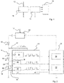
- FIG. 1 shows the basic idea of the invention in a highly schematic manner, according to which a string 10 of series-connected LEDs of a corresponding LED light module, in particular a light module for signal lights in road and rail traffic, is supplied with a current with a specific voltage in a manner known per se via a line 12 supplied and then part of the supplied current is used via a parallel to at least some of the LEDs of the strand circuit for operating a monitoring unit 14.
- the monitoring unit 14 can record certain operating parameters of the light module, such as the current flowing through the strand during operation, the voltage drop across the strand, the temperature in the vicinity of the strand and the luminous flux generated by the strand, and transmit values characteristic of these operating parameters to a higher-level system Output evaluation unit 16.
- the monitoring unit 14 can be fed completely via the power supply of the LED string, so that a separate power supply is advantageously dispensed with and, in particular when the light module is used in signal lights for rail traffic, considerable amounts of cable can sometimes be saved.
- Means such as voltmeters for the LED forward voltage can be provided connected in parallel to one or more LEDs 18 of the string 10 . During operation of the light module, these means can be supplied with power via the power supply 20 of the LEDs.
- the higher-level evaluation unit 16 is supplied via the power supply of the LED string, thus avoiding detection of scattered light when the LED string is switched off in pulses.
- the modern components required for this, such as temperature or photo sensors and microcontrollers, have such a low current consumption that there is no noticeable effect on the luminous flux of the LED string if part of the current to supply units 14 and 16 is branched off.
- an LED string 10 of the type in question for example, eight series-connected LEDs with a current consumption of 350 mA
- a Photo sensor as a means for detecting another operating parameter and a corresponding microcontroller for evaluating the signal of the photo sensor have a current consumption in the range of about 1 to 2 mA. It has been shown that a circuit according to the invention works particularly well when the current consumption of the units 14 and 16 is more than 20 times smaller than the current consumption of the LED string, preferably about 50 to 100 times smaller.
- the light module shown forms a unit that is installed in particular in a signal light and can be externally supplied with power via a line 12 .
- the LED string is formed by a number of series-connected LEDs 18, only a few of which are shown here, with the supply voltage and current being controlled by a ballast unit 20.
- the ballast unit 20, like the evaluation unit 16 is part of the light module, but, like the evaluation unit 16, can also be arranged outside of the actual light module.
- Evaluation unit 16 and upstream unit can be part of a single control unit.
- a monitoring unit 14 is supplied with current at a first point via a circuit parallel to the series connection of the LEDs 18, the various square-wave signals symbolically illustrated in the figure being intended to indicate that the current is pulse-width modulated.
- the monitoring unit 14 in this exemplary embodiment comprises a photo sensor 24 which is arranged in the light module and detects a value which is proportional to the luminous flux which is generated during operation of the LEDs.
- the LEDs are typically arranged rotationally symmetrically, and the light module is provided with an attachment or diffusing screen, as a result of which part of the emitted light is reflected back, which can then be detected by the photo sensor 24 .
- the monitoring unit 14 also includes two voltmeters 26 which, together with corresponding shunt resistors 28 and lines 30, enable an indirect current measurement of the current flowing through the LED string during operation.
- a voltmeter that measures the entire voltage drop across the LED string, which can be particularly advantageous in light modules for use in signal lights for rail traffic.
- the advantages of combined current-voltage monitoring when monitoring LED strings are well known and can be found, for example, in EP 1 992 524 A2 , the content of which is hereby incorporated by reference.
- means provided for detecting the current and/or the voltage can be supplied with current in a pulsed manner via the power supply of the LEDs.
- the values that are representative of the actual current, i.e. the current actually flowing through the LED string, from the voltmeters 26 and a value measured by the photo sensor 24 that is proportional to the luminous flux emitted during operation of the LEDs are fed to the evaluation unit 16, which is Embodiment includes a microcontroller 32 and a controller 34, which is designed to output a control value to the upstream unit 20. It should be noted that the evaluation unit 16 does not have its own power supply, as in previously known light modules, but is advantageously fed by the current supplied to the LEDs 18 in the same way as the monitoring unit 14 .
- the evaluation unit 16 can generate a corresponding control signal, by means of which the ballast unit 20 is prompted to increase the current supplied to the LEDs so that the desired luminous flux.
- the evaluation unit 16 is designed to control the current supplied to the LED string directly or indirectly as a function of the so-called “additional operating parameters”, i.e. here the luminous flux, i.e. either to influence the current directly as part of a more complex control circuit or to communicate with a separate unit, here the ballast unit 20, and to transmit this information that is the basis for controlling the current, and thus to control the current indirectly.
- additional operating parameters i.e. here the luminous flux
- the actual current detection has two channels and is therefore redundant, so that incorrect measurements are practically ruled out because the microcontroller 32 can be designed in such a way that it can generate a corresponding error message if there are deviations between the two signals that are representative of the actual current can then be transmitted in a manner known per se to a higher authority, for example a maintenance center.
- the pulse width modulated operation provided in a preferred embodiment of the invention has two further significant advantages.
- the means for detecting at least one further operating parameter has a photo sensor as in 2 include a complex calculation of the stray light component, since the sensor is only in operation due to the inventive supply via the LED current when the LEDs are switched on, in which case stray light components can be neglected.
- Light that falls on the sensor when the LEDs are switched off between two current pulses is not included in the usual summation by the sensor, so that advantageously inexpensive standard photo sensors, which sum light over a certain period of time to output a measured value, are used can become.
- evaluation unit 16 can check whether photo sensor 24 or voltmeter 26 is supplying signals during the time between two current pulses, from which a malfunction of the photo sensor and/or the voltmeter can be concluded and in a manner known per se way a corresponding error message can be generated.
- the evaluation unit 16 thus has a function for testing the means for detecting the at least one additional operating parameter. It is therefore checked whether the signals output by the ammeter and/or the photo sensor show a profile that corresponds to the profile of the pulse width modulated current.
- the temperature in the vicinity of the LEDs of the strand is recorded, with this value then being able to be used to switch on a fan, for example, via the evaluation unit.
- a fan can also advantageously be supplied with power via the operating current of the LEDs, since the fan only needs to have a low power in typical applications.
- the invention allows in a particularly simple and cost-effective manner for the first time the implementation of a particularly reliable monitoring of the correct functioning of an LED light module, since three different monitoring methods - monitoring the voltage drop across the LED strand, monitoring the current flowing through the strand and detecting a delivered Luminous flux of proportional value - can be combined.
Description
- Die Erfindung betrifft ein LED-Lichtmodul, eine Signalleuchte mit einem solchen Lichtmodul, insbesondere für den Schienen-, Wasser-, Luft- oder Straßenverkehr sowie ein Verfahren zum Betreiben eines solchen Lichtmoduls.
- Lichtemittierende Dioden (LEDs) finden aufgrund ihrer Eigenschaften wie niedrigem Stromverbrauch und hoher Lebensdauer immer häufiger Anwendung als Ersatz von klassischen Leuchtmitteln, und zwar auch in sicherheitsrelevanten Leuchten wie z.B. Verkehrssignalen, Begrenzungsleuchten und Fahrzeugleuchten, worunter hier Leuchten für alle Arten von Land-, Wasser- und Luftfahrzeugen verstanden werden.
- Bei vielen Leuchten ist eine automatisierte Überwachung des korrekten Funktionierens gewünscht oder sogar vorgeschrieben. Während bei klassischen Leuchtmitteln die Überwachung des korrekten Funktionierens meist einfach realisiert werden kann ist (in der Regel genügt es, zu überwachen, ob Strom durch das Leuchtmittel fließt oder nicht; wenn trotz angelegter Spannung kein Strom durch das Leuchtmittel fließt, kann davon ausgegangen werden, dass das Leuchtmittel defekt ist und getauscht werden muss), ist die Funktionsüberwachung bei LEDs aus verschiedenen Gründen nicht trivial. So kann es z.B. dazu kommen, dass eine LED nicht leuchtet, obwohl Strom durch sie fließt.
- Der Totalausfall einer LED kann durch eine kombinierte Strom-Spannungs-Überwachung detektiert werden. Diese Überwachungsart erlaubt es jedoch nicht, eine z.B. durch Alterung der LEDs bedingte Veränderung des Lichtstromes (Degradation) zu erkennen.
- Es ist bekannt, LED-Lichtmodule, d.h. Anordnungen mit üblicherweise mehreren LEDs und weiteren Elementen wie Vorschalteinheiten zum Betrieb der LEDs, mit einem Betriebszeitzähler zu versehen, der die tatsächliche Betriebsdauer der LEDs erfasst. Wird eine bestimmte Betriebsdauer erreicht, werden die LEDs ersetzt, unabhängig davon, ob das von ihnen abgegebene Licht noch zur Erfüllung der ggf. vorgeschriebenen Anforderungen ausreicht oder nicht. Dieses Vorgehen führt dazu, dass regelmäßig LEDs getauscht werden, die noch korrekt funktionieren.
- Es hat sich gezeigt, dass die Alterung von LEDs nicht nur von ihrer reinen Betriebsdauer, sondern auch anderen Faktoren, insbesondere dem Betriebsstrom und der Betriebstemperatur abhängt.
- Eine naheliegende Lösung des Problems der Erfassung einer alterungsbedingten Minderung der Lichtleistung ist die direkte Überwachung des im Betrieb einer LED abgegebenen Lichts mittels entsprechender Sensoren. Dazu schlägt die
DE 197 54 222 eine Überwachungseinheit einer LED vor, bei der das von einer LED abgestrahlte Licht mittels eines Fotosensors gemessen wird. Unterschreitet die Helligkeit des Lichts einen bestimmten Grenzwert, wird ein Warnsignal erzeugt, dass einem Betreiber der LED anzeigt, dass die LED ersetzt werden sollte. - Die aus der
DE 197 54 222 bekannte Art der Überwachung ist gerade bei sog. Streckensignalen für den Schienenverkehr mit unter Umständen sehr hohem Materialaufwand verbunden, denn die Überwachungseinheit wird mit einer eigenen Betriebsspannung versorgt, wobei die entsprechenden Kabel nicht selten über einige hundert, manchmal sogar tausend und mehr Meter von einer entsprechenden Anschlussstelle zu der Überwachungseinheit geführt werden müssen. - Die
US 6,078,148 beschreibt eine Steuerung für einen Transformator mit Primär- und Sekundärwicklungen mit einer Vielzahl von Windungen und Abgriffen zum Ändern der Zahl der wirksamen Windungen und somit einer LED-Stranglichtleistung. Dabei erfolgt eine Steuerung der Abgriffe in Abhängigkeit von einem Betriebsparameter der LEDs für die Aufrechterhaltung der Lichtleistung der LEDs über einem vorbestimmten Pegel auf Basis einer Kombination von Messungen von Spannungen und Strömen an den LEDs. - Die
EP 0 974 947 A1 zeigt eine Lichtsignalanlage mit mindestens einem Signalgeber, dessen Lichtquelle durch in Form einer Matrix angeordnete LEDs gebildet ist, und mit einer Überwachungseinrichtung zum Überprüfen der Leuchtdioden auf deren fehlerfreien Betriebszustand, die einen im Strahlengang der LEDs angeordneten Lichtsensor sowie eine mit diesem verbundene Auswerteeinrichtung zum Vergleichen eines durch den Lichtsensor erzeugten Lichtsensorsignales mit einem vorgegebenen Sollwert aufweist, der einem normalen Betriebszustand der Leuchtdioden entspricht. - Die
DE 10 2005 032 719 A1 zeigt eine Lichtsignalanlage mit mindestens einem Leuchtdioden aufweisenden Signalgeber zur Abgabe eines Lichtzeichens, mit einem Steuergerät zur Ansteuerung, Auswertung und Überwachung der Signalgeber, mit Leitungen zur Energieversorgung und Leitungen zur Datenübertragung zwischen dem Steuergerät und den Signalgebern, und mit einer Schaltungseinrichtung zur Ansteuerung der Signalgeber, sowie je Signalgeber eine in dessen unmittelbare Nähe angeordnete Schaltungseinrichtung, wobei die Signalgeber über einen die Energieversorgungsleitungen und die Datenübertragungsleitungen aufweisenden Leitungsstrang mit dem Steuergerät verbunden sind. - Gemäß der
DE 10 2010 026 012 A1 weist ein Signalgeber zur Erzeugung verschiedenfarbiger Lichtpunkte mit RGB-LEDs einen optischen Sensor zur signaltechnisch sicheren Überwachung des Farbortes und der Lichtstärke des Signalgebers auf. - Zum Betreiben eines Lüfters zeigt
DE 10 2010 013 310 A1 einen an einen Ausgang eines Vorschaltgeräts angeschlossenen Ausgangskreis zur Versorgung eines Leuchtmoduls mit elektrischer Energie, wobei sowohl der Lüfter als auch eine Steuerschaltung zur Versorgung mit elektrischer Energie an den Ausgangskreis angeschlossen sind. - Die
WO 2014/179379 A1 und dieWO 2009/116854 A2 zeigen jeweils ein LED-Lichtmodul gemäß dem Oberbegriff von Anspruch 1. DieUS 8,159,146 B1 zeigt einen LED-Treiber mit Pulsweitenmodulation. - Der Erfindung liegt die Aufgabe zugrunde, ein LED-Lichtmodul mit einer Überwachungseinheit und eine damit ausgestattete Signalleuchte anzugeben, bei der die Überwachungseinheit mit minimalem Materialaufwand und mithin besonders kostengünstig betriebsbereit gemacht werden kann.
- Der Erfindung liegt auch die Aufgabe zugrunde, ein Verfahren zum Betreiben eines LED-Lichtmoduls anzugeben, das in kostensparender Weise bei gleichzeitiger Sicherstellung einer hohen Betriebssicherheit ausgeführt werden kann.
- Die Aufgaben werden gelöst von einem LED-Lichtmodul mit den Merkmalen des Anspruchs 1, einer Signalleuchte mit den Merkmalen des Anspruchs 4 bzw. einem Verfahren mit den Merkmalen des Anspruchs 3.
- Das LED-Lichtmodul gemäß der Erfindung benötigt keine separate Stromversorgung der Überwachungseinheit, sondern diese kann dem Lichtmodul mit Pulsweitenmodulation des zugeführten Strom nutzen, um den abgegebenen Lichtstrom zu überwachen und dabei auf ein aufwendiges Herausrechnen von Streulichtanteilen, die von üblichen Überwachungseinheiten miterfasst werden, zu verzichten. Diese und weitere Vorteile ergeben sich aus der nachfolgenden, rein beispielhaften und nicht beschränkenden Beschreibung von Ausführungsbeispielen in Verbindung mit der Zeichnung, die aus zwei Zeichnungsfiguren besteht.
-
- Fig. 1
- zeigt stark schematisiert ein Blockdiagramm zum grundsätzlichen Verständnis der Arbeitsweise der Erfindung.
- Fig. 2
- zeigt stark schematisiert ein Ausführungsbeispiel eines erfindungsgemäßen Lichtmoduls.
- In der
Fig. 1 ist stark schematisiert die Grundidee der Erfindung dargestellt, wonach einem Strang 10 von in Reihe geschalteten LEDs eines entsprechenden LED-Lichtmoduls, insbesondere eines Lichtmoduls für Signalleuchten des Straßen- und Schienenverkehrs, in an sich bekannter Weise über eine Leitung 12 ein Strom mit einer bestimmten Spannung zugeführt und dann ein Teil des zugeführten Stroms über eine zu zumindest einigen der LEDs des Strangs parallele Schaltung zum Betrieb einer Überwachungseinheit 14 genutzt wird. Die Überwachungseinheit 14 kann bestimmte Betriebsparameter des Lichtmoduls, wie z.B. den im Betrieb durch den Strang fließenden Strom, die am Strang abfallende Spannung, die Temperatur in der Umgebung des Strangs und den von dem Strang erzeugten Lichtstrom erfassen und für diese Betriebsparameter charakteristische Werte an eine übergeordnete Auswerteeinheit 16 ausgeben. - Die Überwachungseinheit 14 kann komplett über die Stromversorgung des LED-Strangs gespeist werden so dass vorteilhaft auf eine separate Stromversorgung verzichtet und damit insbesondere dann, wenn das Lichtmodul in Signalleuchten für den Schienenverkehr eingesetzt wird, teilweise ganz erhebliche Kabelmengen gespart werden können. Es können Mittel wie Spannungsmesser für die LED-Vorwärtsspannung vorgesehen sein, die zu einer oder mehreren LEDs 18 des Strangs 10 parallel geschaltet sind. Diese Mittel können im Betrieb des Lichtmoduls über die Stromversorgung 20 der LEDs mit Strom versorgt werden.
- Die übergeordnete Auswerteeinheit 16 wird über die Stromversorgung des LED-Strangs versorgt, vermeidet also eine Streulichterfassung bei insbesondere pulsweise ausgeschaltetem LED-Strang. Die dafür notwendigen modernen Komponenten, wie z.B. Temperatur- oder Fotosensor sowie Mikrocontroller, besitzen eine so geringe Stromaufnahme, dass es keine merklichen Auswirkungen auf den Lichtstrom des LED-Strangs hat, wenn über die genannte Parallelschaltung ein Teil des Stroms zur Versorgung der Einheiten 14 und 16 abgezweigt wird.
- Typischerweise weist ein LED-Strang 10 der hier in Frage stehenden Art z.B. acht in Reihe geschaltete LEDs mit einer Stromaufnahme von 350 mA auf, während ein Fotosensor als Mittel zur Erfassung eines weiteren Betriebsparameters und ein entsprechender Mikrocontroller zur Auswertung des Signals des Fotosensors eine Stromaufnahme im Bereich von etwa 1 bis 2 mA haben. Es hat sich gezeigt, dass eine erfindungsgemäße Schaltung insbesondere dann hervorragend funktioniert, wenn die Stromaufnahme der Einheiten 14 und 16 mehr als 20-mal kleiner ist als die Stromaufnahme des LED-Strangs, vorzugsweise etwa 50- bis 100-mal kleiner.
- In der
Fig. 2 ist ein Ausführungsbeispiel der Erfindung dargestellt, wobei hier zwei Betriebsparameter erfasst und zur Überwachung und Steuerung des LED-Strangs in der erfindungsgemäßen Weise verwendet werden. Die den Einheiten derFig. 1 entsprechenden Einheiten wurden mit den auch inFig. 1 verwendeten Bezugszeichen versehen. - Das dargestellte Lichtmodul bildet bei diesem Ausführungsbeispiel eine Einheit, die insbesondere in einer Signalleuchte verbaut und über eine Leitung 12 extern mit Strom versorgt werden kann. Der LED-Strang wird von einer Anzahl von in Reihe geschalteten LEDs 18, von denen hier nur einige gezeigt sind, gebildet, wobei die Zuführspannung und der Strom von einer Vorschalteinheit 20 gesteuert werden. Die Vorschalteinheit 20 ist bei diesem Ausführungsbeispiel ebenso wie die Auswerteeinheit 16 Teil des Lichtmoduls, kann aber, ebenso wie die Auswerteeinheit 16, auch außerhalb des eigentlichen Lichtmoduls angeordnet werden. Auswerteeinheit 16 und Vorschalteinheit können Teil einer einzigen Steuereinheit sein.
- Wie durch die Leitung 22 angedeutet, wird einer Überwachungseinheit 14 an einer ersten Stelle über eine zur Reihenschaltung der LEDs 18 parallele Schaltung Strom zugeführt, wobei die verschiedenen in der Figur symbolisch dargestellten Rechtecksignale andeuten sollen, dass der Strom pulsweitenmoduliert ist.
- Wie durch das entsprechende Schaltbild angedeutet, umfasst die Überwachungseinheit 14 bei diesem Ausführungsbeispiel einen Fotosensor 24, der in dem Lichtmodul angeordnet ist und einen zu dem Lichtstrom, der im Betrieb der LEDs erzeugt wird, proportionalen Wert erfasst. Bei Lichtmodulen der hier in Frage stehenden Art sind die LEDs typischerweise rotationssymmetrisch angeordnet, und das Lichtmodul ist mit einer Vorsatz- oder Streuscheibe versehen, wodurch ein Teil des abgegebenen Lichts zurückreflektiert wird, was dann von dem Fotosensor 24 erfasst werden kann.
- Die Überwachungseinheit 14 umfasst bei diesem Ausführungsbeispiel ferner zwei Spannungsmesser 26, die zusammen mit entsprechenden Shunt-Widerständen 28 und Leitungen 30 eine indirekte Strommessung des im Betrieb durch den LED-Strang fließenden Stroms ermöglichen.
- Nicht dargestellt, aber bei einer bevorzugten Ausführungsform vorgesehen, ist ein Spannungsmesser, der die gesamte an dem LED-Strang abfallende Spannung misst, was insbesondere bei Lichtmodulen zum Einsatz in Signalleuchten für den Schienenverkehr vorteilhaft sein kann. Die Vorteile einer kombinierten Strom-Spannungsüberwachung bei der Überwachung von LED-Strängen sind bekannt und zum Beispiel in der
EP 1 992 524 A2 , deren Inhalt hiermit durch Bezugnahme eingebunden wird, offenbart. Bei einer Ausführungsvariante der Erfindung können zur Erfassung des Stroms und/oder der Spannung vorgesehene Mittel über die Stromversorgung der LEDs gepulst mit Strom versorgt werden. - Die von den Spannungsmessern 26 für den Ist-Strom, also den tatsächlich durch den LED-Strang fließenden Strom, repräsentativen Werte und ein zu dem im Betrieb der LEDs abgegebenen Lichtstrom proportionaler, vom Fotosensor 24 gemessener Wert werden der Auswerteeinheit 16 zugeführt, die bei diesem Ausführungsbeispiel einen Mikrocontroller 32 und eine Regelung 34 umfasst, die zur Ausgabe eines Steuerwertes an die Vorschalteinheit 20 ausgebildet ist. Man beachte, dass die Auswerteeinheit 16 nicht, wie bei vormals bekannten Lichtmodulen, über eine eigene Stromversorgung verfügt, sondern vorteilhaft ebenso wie die Überwachungseinheit 14 von dem den LEDs 18 zugeführten Strom gespeist wird. Erfasst nun der Fotosensor, dass zum Beispiel aufgrund einer Degradation der LEDs 18 der im Betrieb abgegebene Lichtstrom nachlässt, kann die Auswerteeinheit 16 ein entsprechendes Steuersignal erzeugen, mittels welchem die Vorschalteinheit 20 veranlasst wird, den den LEDs zugeführten Strom so zu erhöhen, dass sich der gewünschte Lichtstrom ergibt. Mit der oben genannten Randbedingung, dass die Stromaufnahme von Überwachungseinheit 14 und Auswerteeinheit 16 deutlich kleiner ist als die Stromaufnahme der LEDs, kann die Reduzierung der Helligkeit der LEDs aufgrund der Stromabzweigung vernachlässigt werden, zumal eine solche ohnehin vom Fotosensor 24 erfasst und zu einer Nachregelung des Stroms führte.
- Die Auswerteeinheit 16 ist dazu ausgebildet, den dem LED-Strang zugeführten Strom in Abhängigkeit von dem sog. "weiteren Betriebsparameter", hier also dem Lichtstrom, direkt oder indirekt zu steuern, also entweder als Teil einer komplexeren Steuerschaltung direkt Einfluss auf den Strom zu nehmen oder aber mit einer gesonderten Einheit, hier der Vorschalteinheit 20 zu kommunizieren und dieser Informationen zu übermitteln, die Basis für eine Steuerung des Stroms sind, und so den Strom indirekt zu steuern.
- Bei dem in
Fig. 2 gezeigten Ausführungsbeispiel ist die Ist-Stromerfassung zweikanalig, mithin redundant ausgebildet, so dass Fehlmessungen praktisch ausgeschlossen sind, weil der Mikrocontroller 32 so ausgebildet sein kann, dass er bei Abweichungen zwischen den beiden für den Ist-Strom repräsentativen Signalen eine entsprechende Fehlermeldung erzeugen kann, die dann in an sich bekannter Weise an eine übergeordnete Stelle, zum Beispiel eine Wartungszentrale, übermittelt werden kann. - Außer der bereits genannten Sicherstellung eines stabilen Farbortes hat der bei einer bevorzugten Ausführungsform der Erfindung vorgesehene pulsweitenmodulierte Betrieb zwei wesentliche weitere Vorteile. So erübrigt sich in denjenigen Fällen, in denen die Mittel zur Erfassung wenigstens eines weiteren Betriebsparameters einen Fotosensor wie in
Fig. 2 umfassen, ein aufwändiges Herausrechnen des Streulichtanteils, da der Sensor durch die erfindungsgemäße Versorgung über den LED-Strom nur dann im Betrieb ist, wenn auch die LEDs eingeschaltet sind, wobei dann Streulichtanteile vernachlässigt werden können. Licht, das auf den Sensor fällt, wenn die LEDs zwischen zwei Strompulsen ausgeschaltet sind, wird vom Sensor nicht in die übliche Aufsummierung einbezogen, so dass in vorteilhafter Weise kostengünstige Standard-Fotosensoren, die zur Ausgabe eines Messwertes Licht über einen bestimmten Zeitraum aufsummieren, verwendet werden können. - Ein weiterer Vorteil des pulsweitenmodulierten Betriebes ist, dass die Auswerteeinheit 16 prüfen kann, ob der Fotosensor 24 oder die Spannungsmesser 26 Signale währen der Zeit zwischen zwei Strompulsen liefern, woraus dann auf eine Fehlfunktion des Fotosensors und/oder der Spannungsmesser geschlossen und in an sich bekannter Weise eine entsprechende Fehlermeldung erzeugt werden kann. Damit verfügt die Auswerteeinheit 16 quasi über eine Funktion zum Testen der Mittel zur Erfassung des wenigstens einen weiteren Betriebsparameters. Es wird also geprüft, ob die von dem Strommesser und/oder dem Fotosensor ausgegebenen Signale einen Verlauf zeigen, der dem Verlauf des pulsweitenmodulierten Stroms entspricht.
- Im Rahmen des Erfindungsgedankens sind zahlreiche Abwandlungen und Weiterbildungen möglich, die sich insbesondere auf die Art und die Anzahl der Mittel zur Erfassung von Betriebsparametern der LEDs beziehen. So ist bei einer bevorzugten Ausführungsform der Erfindung vorgesehen, die Temperatur in der Umgebung der LEDs des Strangs zu erfassen, wobei dann mit diesem Wert über die Auswerteeinheit zum Beispiel ein Lüfter angeschaltet werden kann. Auch ein solcher Lüfter kann vorteilhaft über den Betriebsstrom der LEDs mit Strom versorgt werden, da bei typischen Anwendungsfällen der Lüfter nur eine geringe Leistung haben muss.
- Die Erfindung erlaubt in besonders einfacher und kostengünstiger Weise erstmals die Realisierung einer besonders sicheren Überwachung des korrekten Funktionierens eines LED-Lichtmoduls, da drei verschiedene Überwachungsmethoden - Überwachung der am LED-Strang abfallenden Spannung, Überwachung des durch den Strang fließenden Stroms und Erfassung eines zum abgegebenen Lichtstrom proportionalen Wertes - kombiniert werden können.
-
- 10
- LED-Strang
- 12
- Leitung
- 14
- Überwachungseinheit
- 16
- Auswerteeinheit
- 18
- LEDs
- 20
- Vorschalteinheit
- 22
- Leitung
- 24
- Fotosensor
- 26
- Spannungsmesser
- 28
- Shunt-Widerstände
- 30
- Leitungen
- 32
- Mikrocontroller
- 34
- Regelung
Claims (4)
- LED-Lichtmodul, insbesondere für Signalleuchten des Straßen- und Schienenverkehrs, umfassend- wenigstens einen Strang (10) von in Reihe geschalteten LEDs (18),- Mittel zur Überwachung (26, 28, 30) des im Betrieb des Strangs durch den Strang fließenden Stroms und/oder der an dem Strang abfallenden Spannung,- eine Stromversorgung (20) der LEDs,- eine Überwachungseinheit (14), umfassend Mittel zur Erfassung wenigstens eines weiteren Betriebsparameters der LEDs, die einen Sensor (24) zur Erfassung eines zu einem im Betrieb des Lichtmoduls abgegebenen Lichtstrom proportionalen Wertes und zur Ausgabe eines Signals auf Basis des Wertes umfassen, undeine Auswerteeinheit (16), die dazu ausgebildet ist, die Stromversorgung (20) der LEDs für einen dem LED-Strang zugeführten Strom in Abhängigkeit des Signals durch Pulsweitenmodulation zu steuern,
dadurch gekennzeichnet, dassim Betrieb des Lichtmoduls die Überwachungseinheit (14) ebenfalls über die Stromversorgung (20) der LEDs (18) mit Strom entsprechend der Pulsweitenmodulation versorgt wird. - LED-Lichtmodul nach Anspruch 1, dadurch gekennzeichnet, dass die Auswerteeinheit (16) über eine Funktion zum Testen der Mittel zur Erfassung des wenigstens einen weiteren Betriebsparameters verfügt.
- Verfahren zum Betreiben eines LED-Lichtmoduls, insbesondere für Signalleuchten des Straßen- und Schienenverkehrs, wobei- das Lichtmodul über einen Strang (10) von in Reihe geschalteten LEDs verfügt,- der im Betrieb durch den Strang fließende Strom und/oder die an dem Strang abfallende Spannung überwacht werden,- mit einem Sensor (24) einer Überwachungseinheit (14) ein zu einem im Betrieb des Lichtmoduls abgegebenen Lichtstrom proportionaler Wert erfasst und ein Signal auf Basis des Wertes an eine übergeordnete Auswerteeinheit (16) ausgegeben wird undder dem Strang im Betrieb zugeführte Strom in Abhängigkeit des Wertes durch Pulsweitenmodulation der Stromversorgung der LEDs gesteuert wird,
dadurch gekennzeichnet, dassim Betrieb des Lichtmoduls ebenfalls die Überwachungseinheit (14) über die Stromversorgung der LEDs mit Strom entsprechend der Pulsweitenmodulation versorgt wird. - Signalleuchte, insbesondere für den Straßen- und Schienenverkehr, dadurch gekennzeichnet, dass sie ein LED-Lichtmodul nach Anspruch 1 oder 2 umfasst.
Priority Applications (2)
| Application Number | Priority Date | Filing Date | Title |
|---|---|---|---|
| HRP20221261TT HRP20221261T1 (hr) | 2014-12-23 | 2015-12-14 | Led svjetlosni modul, signalno svijetlo sa takvim svjetlosnim modulom, kao i postupak rada takvog svjetlosnog modula |
| RS20220947A RS63645B1 (sr) | 2014-12-23 | 2015-12-14 | Led svetlosni modul, signalno svetlo sa takvim svetlosnim modulom, kao i postupak rada takvog svetlosnog modula |
Applications Claiming Priority (1)
| Application Number | Priority Date | Filing Date | Title |
|---|---|---|---|
| DE102014119623.6A DE102014119623A1 (de) | 2014-12-23 | 2014-12-23 | LED-Lichtmodul, Signalleuchte mit einem solchen Lichtmodul sowie Verfahren zum Betreiben eines solchen Lichtmoduls |
Publications (3)
| Publication Number | Publication Date |
|---|---|
| EP3038433A2 EP3038433A2 (de) | 2016-06-29 |
| EP3038433A3 EP3038433A3 (de) | 2016-07-27 |
| EP3038433B1 true EP3038433B1 (de) | 2022-07-13 |
Family
ID=54979405
Family Applications (1)
| Application Number | Title | Priority Date | Filing Date |
|---|---|---|---|
| EP15199957.0A Active EP3038433B1 (de) | 2014-12-23 | 2015-12-14 | Led-lichtmodul, signalleuchte mit einem solchen lichtmodul sowie verfahren zum betreiben eines solchen lichtmoduls |
Country Status (10)
| Country | Link |
|---|---|
| EP (1) | EP3038433B1 (de) |
| DE (1) | DE102014119623A1 (de) |
| DK (1) | DK3038433T3 (de) |
| ES (1) | ES2928388T3 (de) |
| HR (1) | HRP20221261T1 (de) |
| HU (1) | HUE060173T2 (de) |
| LT (1) | LT3038433T (de) |
| PL (1) | PL3038433T3 (de) |
| PT (1) | PT3038433T (de) |
| RS (1) | RS63645B1 (de) |
Families Citing this family (1)
| Publication number | Priority date | Publication date | Assignee | Title |
|---|---|---|---|---|
| EP4016495A1 (de) * | 2020-12-18 | 2022-06-22 | Siemens Mobility GmbH | Verfahren zur ansteuerungsdiagnose |
Family Cites Families (13)
| Publication number | Priority date | Publication date | Assignee | Title |
|---|---|---|---|---|
| US5783909A (en) * | 1997-01-10 | 1998-07-21 | Relume Corporation | Maintaining LED luminous intensity |
| DE19754222A1 (de) | 1997-12-06 | 1999-06-10 | Volkswagen Ag | Vorrichtung zur Funktionskontrolle von Lumineszenzdioden |
| US7740371B1 (en) * | 1998-03-19 | 2010-06-22 | Charles A. Lemaire | Method and apparatus for pulsed L.E.D. illumination for a camera |
| DE59911260D1 (de) * | 1998-07-23 | 2005-01-20 | Siemens Ag | Lichtsignalanlage sowie Verfahren zum Überwachen der Lichtsignalanlage |
| US6078148A (en) * | 1998-10-09 | 2000-06-20 | Relume Corporation | Transformer tap switching power supply for LED traffic signal |
| DE102005032719A1 (de) * | 2005-07-13 | 2007-01-25 | Siemens Ag | Lichtsignalanlage, insbesondere für den Straßenverkehr |
| JP4962939B2 (ja) | 2006-03-03 | 2012-06-27 | トヨタ自動車株式会社 | 車両および車両の情報機器 |
| US7969097B2 (en) * | 2006-05-31 | 2011-06-28 | Cree, Inc. | Lighting device with color control, and method of lighting |
| DE102007021836A1 (de) * | 2007-05-07 | 2008-11-20 | Pintsch Bamag Antriebs- Und Verkehrstechnik Gmbh | LED Anordnung für Lichtsignalgeber insbesondere für Bahnübergänge sowie Lichtsignalgeber insbesondere für Bahnübergänge mit einer solchen LED-Anordnung |
| EP2996441B1 (de) * | 2008-03-17 | 2020-12-16 | eldoLAB Holding B.V. | Led-leuchte und led-anordnung |
| DE102010013310B4 (de) * | 2010-03-29 | 2012-02-23 | Panasonic Electric Works Vossloh-Schwabe Gmbh | Betriebsschaltung zum Betreiben eines Lüfters für ein Leuchtmodul |
| DE102010026012A1 (de) * | 2010-06-29 | 2011-12-29 | Siemens Aktiengesellschaft | LED-Lichtsignal |
| CA2910222C (en) * | 2013-04-30 | 2022-08-30 | Digital Lumens Incorporated | Operating light emitting diodes at low temperature |
-
2014
- 2014-12-23 DE DE102014119623.6A patent/DE102014119623A1/de not_active Withdrawn
-
2015
- 2015-12-14 DK DK15199957.0T patent/DK3038433T3/da active
- 2015-12-14 ES ES15199957T patent/ES2928388T3/es active Active
- 2015-12-14 EP EP15199957.0A patent/EP3038433B1/de active Active
- 2015-12-14 PL PL15199957.0T patent/PL3038433T3/pl unknown
- 2015-12-14 RS RS20220947A patent/RS63645B1/sr unknown
- 2015-12-14 HU HUE15199957A patent/HUE060173T2/hu unknown
- 2015-12-14 HR HRP20221261TT patent/HRP20221261T1/hr unknown
- 2015-12-14 LT LTEP15199957.0T patent/LT3038433T/lt unknown
- 2015-12-14 PT PT151999570T patent/PT3038433T/pt unknown
Also Published As
| Publication number | Publication date |
|---|---|
| EP3038433A2 (de) | 2016-06-29 |
| RS63645B1 (sr) | 2022-10-31 |
| PL3038433T3 (pl) | 2022-12-27 |
| LT3038433T (lt) | 2022-11-10 |
| EP3038433A3 (de) | 2016-07-27 |
| HUE060173T2 (hu) | 2023-02-28 |
| PT3038433T (pt) | 2022-10-17 |
| DE102014119623A1 (de) | 2016-06-23 |
| HRP20221261T1 (hr) | 2022-12-09 |
| ES2928388T3 (es) | 2022-11-17 |
| DK3038433T3 (da) | 2022-10-24 |
Similar Documents
| Publication | Publication Date | Title |
|---|---|---|
| EP1417864B1 (de) | Lichtzeichen zur verkehrssteuerung und verfahren zur funktionsüberwachung eines solchen zeichens | |
| DE102010005088A1 (de) | Lichtsignal | |
| DE102007018224A1 (de) | LED-Leuchte mit stabilisiertem Lichtstrom und stabilisierter Lichtfarbe | |
| EP2131628B1 (de) | Signalgeber | |
| EP0974947B1 (de) | Lichtsignalanlage sowie Verfahren zum Überwachen der Lichtsignalanlage | |
| EP2589264B1 (de) | Led-lichtsignal | |
| DE102005023295A1 (de) | Schaltung zur Ansteuerung und Überwachung eines Lichtsignals | |
| DE10227487A1 (de) | Beleuchtungsvorrichtung | |
| EP3038433B1 (de) | Led-lichtmodul, signalleuchte mit einem solchen lichtmodul sowie verfahren zum betreiben eines solchen lichtmoduls | |
| DE102006056148B4 (de) | Verfahren zur Funktionsüberwachung einer Lichtsignalanlage und Verkehrssteuerungs-Lichtsignalanlage | |
| EP2687418B1 (de) | LED-Streckensignal für den Schienenverkehr sowie Schnittstelle für ein solches LED-Streckensignal | |
| EP2000360A1 (de) | Anhängeranschlussgerät | |
| WO2007036509A1 (de) | Verfahren und einrichtung zur überwachung des lichtsignals eines elektro-optischen leuchtelements, insbesondere einer im bahnbetrieb verwendeten hochstrom-led eines sicheren bahnsignals | |
| WO2009034014A2 (de) | Erkennen und kompensieren von led ausfällen in langen led-ketten | |
| DE60302434T2 (de) | Erkennung von Anhängeranwesenheit und -typ durch Stromdetektion | |
| EP2710394B1 (de) | Vorrichtung und verfahren zur zustandsüberwachung eines anlagenbestandteils | |
| EP2866524B1 (de) | Anordnung und Verfahren zur Überwachung mehrerer LED-Stränge sowie LED-Leuchte mit einer solchen Anordnung | |
| EP3165053B1 (de) | Vorrichtung und verfahren zum überwachen eines eine lichtemittierende diode umfassenden signalgebers einer lichtsignalanlage | |
| EP3072775B1 (de) | Verfahren zur Rückmeldung des Leuchtens einer Signallampe in einem Verkehrssignal an eine Überwachungsvorrichtung | |
| EP1341402A2 (de) | Beleuchtungsanordnung mit einem LED-Modul | |
| EP3787379A1 (de) | System und verfahren zur überprüfung des leuchtens eines mit mindestens einem led-leuchtmittel ausgerüsteten leuchtpunkts | |
| DE102014008421B4 (de) | LED-Leuchtvorrichtung | |
| DE102010012800A1 (de) | LED-Lichtsignal | |
| DE102013110003B3 (de) | LED-Leuchte mit einer Anordnung zur Überwachung von LEDs | |
| DE102006056147A1 (de) | Verfahren zur Funktionsüberwachung von lichtemittierenden Halbleiterbauelementen |
Legal Events
| Date | Code | Title | Description |
|---|---|---|---|
| PUAI | Public reference made under article 153(3) epc to a published international application that has entered the european phase |
Free format text: ORIGINAL CODE: 0009012 |
|
| PUAL | Search report despatched |
Free format text: ORIGINAL CODE: 0009013 |
|
| AK | Designated contracting states |
Kind code of ref document: A2 Designated state(s): AL AT BE BG CH CY CZ DE DK EE ES FI FR GB GR HR HU IE IS IT LI LT LU LV MC MK MT NL NO PL PT RO RS SE SI SK SM TR |
|
| AX | Request for extension of the european patent |
Extension state: BA ME |
|
| AK | Designated contracting states |
Kind code of ref document: A3 Designated state(s): AL AT BE BG CH CY CZ DE DK EE ES FI FR GB GR HR HU IE IS IT LI LT LU LV MC MK MT NL NO PL PT RO RS SE SI SK SM TR |
|
| AX | Request for extension of the european patent |
Extension state: BA ME |
|
| RIC1 | Information provided on ipc code assigned before grant |
Ipc: H05B 33/08 20060101AFI20160621BHEP |
|
| RIN1 | Information on inventor provided before grant (corrected) |
Inventor name: WENZLER, PATRICK Inventor name: DEPKE, JAN |
|
| RIN1 | Information on inventor provided before grant (corrected) |
Inventor name: DEPKE, JAN Inventor name: WENZLER, PATRICK |
|
| STAA | Information on the status of an ep patent application or granted ep patent |
Free format text: STATUS: REQUEST FOR EXAMINATION WAS MADE |
|
| 17P | Request for examination filed |
Effective date: 20161128 |
|
| RBV | Designated contracting states (corrected) |
Designated state(s): AL AT BE BG CH CY CZ DE DK EE ES FI FR GB GR HR HU IE IS IT LI LT LU LV MC MK MT NL NO PL PT RO RS SE SI SK SM TR |
|
| STAA | Information on the status of an ep patent application or granted ep patent |
Free format text: STATUS: EXAMINATION IS IN PROGRESS |
|
| 17Q | First examination report despatched |
Effective date: 20181102 |
|
| STAA | Information on the status of an ep patent application or granted ep patent |
Free format text: STATUS: EXAMINATION IS IN PROGRESS |
|
| RAP1 | Party data changed (applicant data changed or rights of an application transferred) |
Owner name: PINTSCH GMBH |
|
| STAA | Information on the status of an ep patent application or granted ep patent |
Free format text: STATUS: EXAMINATION IS IN PROGRESS |
|
| REG | Reference to a national code |
Ref country code: DE Ref legal event code: R079 Ref document number: 502015015953 Country of ref document: DE Free format text: PREVIOUS MAIN CLASS: H05B0033080000 Ipc: H05B0045120000 |
|
| GRAP | Despatch of communication of intention to grant a patent |
Free format text: ORIGINAL CODE: EPIDOSNIGR1 |
|
| STAA | Information on the status of an ep patent application or granted ep patent |
Free format text: STATUS: GRANT OF PATENT IS INTENDED |
|
| RIC1 | Information provided on ipc code assigned before grant |
Ipc: H05B 45/50 20220101ALI20220210BHEP Ipc: H05B 45/12 20200101AFI20220210BHEP |
|
| INTG | Intention to grant announced |
Effective date: 20220225 |
|
| GRAS | Grant fee paid |
Free format text: ORIGINAL CODE: EPIDOSNIGR3 |
|
| GRAA | (expected) grant |
Free format text: ORIGINAL CODE: 0009210 |
|
| STAA | Information on the status of an ep patent application or granted ep patent |
Free format text: STATUS: THE PATENT HAS BEEN GRANTED |
|
| AK | Designated contracting states |
Kind code of ref document: B1 Designated state(s): AL AT BE BG CH CY CZ DE DK EE ES FI FR GB GR HR HU IE IS IT LI LT LU LV MC MK MT NL NO PL PT RO RS SE SI SK SM TR |
|
| REG | Reference to a national code |
Ref country code: GB Ref legal event code: FG4D Free format text: NOT ENGLISH |
|
| REG | Reference to a national code |
Ref country code: CH Ref legal event code: EP |
|
| REG | Reference to a national code |
Ref country code: IE Ref legal event code: FG4D Free format text: LANGUAGE OF EP DOCUMENT: GERMAN |
|
| REG | Reference to a national code |
Ref country code: DE Ref legal event code: R096 Ref document number: 502015015953 Country of ref document: DE |
|
| REG | Reference to a national code |
Ref country code: AT Ref legal event code: REF Ref document number: 1504937 Country of ref document: AT Kind code of ref document: T Effective date: 20220815 |
|
| REG | Reference to a national code |
Ref country code: RO Ref legal event code: EPE |
|
| REG | Reference to a national code |
Ref country code: PT Ref legal event code: SC4A Ref document number: 3038433 Country of ref document: PT Date of ref document: 20221017 Kind code of ref document: T Free format text: AVAILABILITY OF NATIONAL TRANSLATION Effective date: 20221010 |
|
| REG | Reference to a national code |
Ref country code: FI Ref legal event code: FGE |
|
| REG | Reference to a national code |
Ref country code: DK Ref legal event code: T3 Effective date: 20221017 Ref country code: NO Ref legal event code: T2 Effective date: 20220713 |
|
| REG | Reference to a national code |
Ref country code: SE Ref legal event code: TRGR |
|
| REG | Reference to a national code |
Ref country code: NL Ref legal event code: FP |
|
| REG | Reference to a national code |
Ref country code: ES Ref legal event code: FG2A Ref document number: 2928388 Country of ref document: ES Kind code of ref document: T3 Effective date: 20221117 |
|
| REG | Reference to a national code |
Ref country code: GR Ref legal event code: EP Ref document number: 20220402041 Country of ref document: GR Effective date: 20221109 |
|
| REG | Reference to a national code |
Ref country code: SK Ref legal event code: T3 Ref document number: E 40659 Country of ref document: SK |
|
| REG | Reference to a national code |
Ref country code: HR Ref legal event code: T1PR Ref document number: P20221261 Country of ref document: HR |
|
| REG | Reference to a national code |
Ref country code: EE Ref legal event code: FG4A Ref document number: E022824 Country of ref document: EE Effective date: 20221013 |
|
| REG | Reference to a national code |
Ref country code: HR Ref legal event code: ODRP Ref document number: P20221261 Country of ref document: HR Payment date: 20221205 Year of fee payment: 8 |
|
| PGFP | Annual fee paid to national office [announced via postgrant information from national office to epo] |
Ref country code: DE Payment date: 20221122 Year of fee payment: 8 |
|
| REG | Reference to a national code |
Ref country code: DE Ref legal event code: R082 Ref document number: 502015015953 Country of ref document: DE Representative=s name: MEISSNER BOLTE PATENTANWAELTE RECHTSANWAELTE P, DE |
|
| PG25 | Lapsed in a contracting state [announced via postgrant information from national office to epo] |
Ref country code: IS Free format text: LAPSE BECAUSE OF FAILURE TO SUBMIT A TRANSLATION OF THE DESCRIPTION OR TO PAY THE FEE WITHIN THE PRESCRIBED TIME-LIMIT Effective date: 20221113 |
|
| PGFP | Annual fee paid to national office [announced via postgrant information from national office to epo] |
Ref country code: PL Payment date: 20221206 Year of fee payment: 8 Ref country code: GR Payment date: 20221219 Year of fee payment: 8 Ref country code: BE Payment date: 20221220 Year of fee payment: 8 |
|
| REG | Reference to a national code |
Ref country code: HU Ref legal event code: AG4A Ref document number: E060173 Country of ref document: HU |
|
| REG | Reference to a national code |
Ref country code: DE Ref legal event code: R097 Ref document number: 502015015953 Country of ref document: DE |
|
| PG25 | Lapsed in a contracting state [announced via postgrant information from national office to epo] |
Ref country code: SM Free format text: LAPSE BECAUSE OF FAILURE TO SUBMIT A TRANSLATION OF THE DESCRIPTION OR TO PAY THE FEE WITHIN THE PRESCRIBED TIME-LIMIT Effective date: 20220713 |
|
| PGFP | Annual fee paid to national office [announced via postgrant information from national office to epo] |
Ref country code: ES Payment date: 20230119 Year of fee payment: 8 Ref country code: CH Payment date: 20230103 Year of fee payment: 8 |
|
| PLBE | No opposition filed within time limit |
Free format text: ORIGINAL CODE: 0009261 |
|
| STAA | Information on the status of an ep patent application or granted ep patent |
Free format text: STATUS: NO OPPOSITION FILED WITHIN TIME LIMIT |
|
| 26N | No opposition filed |
Effective date: 20230414 |
|
| PG25 | Lapsed in a contracting state [announced via postgrant information from national office to epo] |
Ref country code: AL Free format text: LAPSE BECAUSE OF FAILURE TO SUBMIT A TRANSLATION OF THE DESCRIPTION OR TO PAY THE FEE WITHIN THE PRESCRIBED TIME-LIMIT Effective date: 20220713 |
|
| P01 | Opt-out of the competence of the unified patent court (upc) registered |
Effective date: 20230601 |
|
| PG25 | Lapsed in a contracting state [announced via postgrant information from national office to epo] |
Ref country code: IE Free format text: LAPSE BECAUSE OF NON-PAYMENT OF DUE FEES Effective date: 20221214 |
|
| REG | Reference to a national code |
Ref country code: HR Ref legal event code: ODRP Ref document number: P20221261 Country of ref document: HR Payment date: 20231208 Year of fee payment: 9 |
|
| PGFP | Annual fee paid to national office [announced via postgrant information from national office to epo] |
Ref country code: SK Payment date: 20231212 Year of fee payment: 9 |
|
| PGFP | Annual fee paid to national office [announced via postgrant information from national office to epo] |
Ref country code: GB Payment date: 20231219 Year of fee payment: 9 |
|
| PGFP | Annual fee paid to national office [announced via postgrant information from national office to epo] |
Ref country code: TR Payment date: 20231211 Year of fee payment: 9 Ref country code: SI Payment date: 20231208 Year of fee payment: 9 Ref country code: SE Payment date: 20231222 Year of fee payment: 9 Ref country code: RS Payment date: 20231212 Year of fee payment: 9 Ref country code: RO Payment date: 20231213 Year of fee payment: 9 Ref country code: PT Payment date: 20231211 Year of fee payment: 9 Ref country code: NO Payment date: 20231219 Year of fee payment: 9 Ref country code: NL Payment date: 20231226 Year of fee payment: 9 Ref country code: LV Payment date: 20231221 Year of fee payment: 9 Ref country code: LU Payment date: 20231226 Year of fee payment: 9 Ref country code: LT Payment date: 20231208 Year of fee payment: 9 Ref country code: IT Payment date: 20231221 Year of fee payment: 9 Ref country code: HU Payment date: 20231212 Year of fee payment: 9 Ref country code: HR Payment date: 20231208 Year of fee payment: 9 Ref country code: FR Payment date: 20231226 Year of fee payment: 9 Ref country code: FI Payment date: 20231228 Year of fee payment: 9 Ref country code: EE Payment date: 20231219 Year of fee payment: 9 Ref country code: DK Payment date: 20231222 Year of fee payment: 9 Ref country code: CZ Payment date: 20231211 Year of fee payment: 9 Ref country code: BG Payment date: 20231220 Year of fee payment: 9 Ref country code: AT Payment date: 20231219 Year of fee payment: 9 |
|
| PGFP | Annual fee paid to national office [announced via postgrant information from national office to epo] |
Ref country code: PL Payment date: 20231211 Year of fee payment: 9 Ref country code: BE Payment date: 20231226 Year of fee payment: 9 |
|
| PGFP | Annual fee paid to national office [announced via postgrant information from national office to epo] |
Ref country code: ES Payment date: 20240118 Year of fee payment: 9 |