EP3038433B1 - Module d'eclairage del, feu de signalisation comprenant un tel module d'eclairage et procede de fonctionnement d'un tel module d'eclairage - Google Patents
Module d'eclairage del, feu de signalisation comprenant un tel module d'eclairage et procede de fonctionnement d'un tel module d'eclairage Download PDFInfo
- Publication number
- EP3038433B1 EP3038433B1 EP15199957.0A EP15199957A EP3038433B1 EP 3038433 B1 EP3038433 B1 EP 3038433B1 EP 15199957 A EP15199957 A EP 15199957A EP 3038433 B1 EP3038433 B1 EP 3038433B1
- Authority
- EP
- European Patent Office
- Prior art keywords
- light module
- leds
- current
- light
- string
- Prior art date
- Legal status (The legal status is an assumption and is not a legal conclusion. Google has not performed a legal analysis and makes no representation as to the accuracy of the status listed.)
- Active
Links
- 238000000034 method Methods 0.000 title claims description 7
- 238000012544 monitoring process Methods 0.000 claims description 35
- 238000011156 evaluation Methods 0.000 claims description 18
- 230000004907 flux Effects 0.000 claims description 12
- 238000012360 testing method Methods 0.000 claims description 2
- 230000008901 benefit Effects 0.000 description 4
- 230000032683 aging Effects 0.000 description 3
- 238000001514 detection method Methods 0.000 description 3
- 238000005259 measurement Methods 0.000 description 3
- 230000011664 signaling Effects 0.000 description 3
- 230000005540 biological transmission Effects 0.000 description 2
- 230000015556 catabolic process Effects 0.000 description 2
- 238000006731 degradation reaction Methods 0.000 description 2
- 238000010586 diagram Methods 0.000 description 2
- 239000000463 material Substances 0.000 description 2
- 230000009467 reduction Effects 0.000 description 2
- 238000011144 upstream manufacturing Methods 0.000 description 2
- XLYOFNOQVPJJNP-UHFFFAOYSA-N water Substances O XLYOFNOQVPJJNP-UHFFFAOYSA-N 0.000 description 2
- 230000008859 change Effects 0.000 description 1
- 230000003247 decreasing effect Effects 0.000 description 1
- 230000002950 deficient Effects 0.000 description 1
- 238000011161 development Methods 0.000 description 1
- 230000018109 developmental process Effects 0.000 description 1
- 230000000694 effects Effects 0.000 description 1
- 230000007257 malfunction Effects 0.000 description 1
- 239000011159 matrix material Substances 0.000 description 1
- 238000012986 modification Methods 0.000 description 1
- 230000004048 modification Effects 0.000 description 1
- 238000012806 monitoring device Methods 0.000 description 1
- 230000003287 optical effect Effects 0.000 description 1
- 238000004804 winding Methods 0.000 description 1
Images
Classifications
-
- H—ELECTRICITY
- H05—ELECTRIC TECHNIQUES NOT OTHERWISE PROVIDED FOR
- H05B—ELECTRIC HEATING; ELECTRIC LIGHT SOURCES NOT OTHERWISE PROVIDED FOR; CIRCUIT ARRANGEMENTS FOR ELECTRIC LIGHT SOURCES, IN GENERAL
- H05B45/00—Circuit arrangements for operating light-emitting diodes [LED]
- H05B45/50—Circuit arrangements for operating light-emitting diodes [LED] responsive to malfunctions or undesirable behaviour of LEDs; responsive to LED life; Protective circuits
-
- H—ELECTRICITY
- H05—ELECTRIC TECHNIQUES NOT OTHERWISE PROVIDED FOR
- H05B—ELECTRIC HEATING; ELECTRIC LIGHT SOURCES NOT OTHERWISE PROVIDED FOR; CIRCUIT ARRANGEMENTS FOR ELECTRIC LIGHT SOURCES, IN GENERAL
- H05B45/00—Circuit arrangements for operating light-emitting diodes [LED]
- H05B45/10—Controlling the intensity of the light
- H05B45/12—Controlling the intensity of the light using optical feedback
Definitions
- the invention relates to an LED light module, a signal light with such a light module, in particular for rail, water, air or road traffic, and a method for operating such a light module.
- LEDs Due to their properties such as low power consumption and long service life, light-emitting diodes (LEDs) are increasingly being used as a replacement for classic light sources, including in safety-relevant lights such as traffic signals, side lights and vehicle lights, including lights for all types of land, water and and aircraft are understood.
- Total failure of an LED can be detected by combined current-voltage monitoring.
- this type of monitoring does not allow a change in the luminous flux (degradation) caused, for example, by aging of the LEDs to be detected.
- LED light modules i.e. arrangements with usually several LEDs and other elements such as ballast units for operating the LEDs, with an operating time counter that records the actual operating time of the LEDs.
- an operating time counter that records the actual operating time of the LEDs.
- the DE 197 54 222 proposes a monitoring unit for an LED, in which the light emitted by an LED is measured using a photo sensor. If the brightness of the light falls below a certain limit value, a warning signal is generated which indicates to an operator of the LED that the LED should be replaced.
- the ones from the DE 197 54 222 can be associated with very high material costs, because the monitoring unit is supplied with its own operating voltage, with the corresponding cables often being a few hundred, sometimes even a thousand or more meters from a corresponding one Connection point must be performed to the monitoring unit.
- the U.S. 6,078,148 describes a control for a transformer with primary and secondary windings with a large number of turns and taps for changing the number of effective turns and thus an LED string light output.
- the taps are controlled as a function of an operating parameter of the LEDs for maintaining the light output LEDs above a predetermined level based on a combination of measurements of voltages and currents on the LEDs.
- the EP 0 974 947 A1 shows a traffic signal system with at least one signal transmitter, the light source of which is formed by LEDs arranged in the form of a matrix, and with a monitoring device for checking the light-emitting diodes for their error-free operating status, which has a light sensor arranged in the beam path of the LEDs and an evaluation device connected to it for comparing a having a light sensor signal generated by the light sensor with a predetermined desired value, which corresponds to a normal operating state of the light-emitting diodes.
- the DE 10 2005 032 719 A1 shows a traffic signal system with at least one signal transmitter having light-emitting diodes for emitting a light signal, with a control unit for actuating, evaluating and monitoring the signal transmitter, with lines for power supply and lines for data transmission between the control unit and the signal transmitter, and with a switching device for controlling the signal transmitter, as well as a switching device for each signal transmitter arranged in its immediate vicinity, the signal transmitters being connected to the control unit via a line section having the energy supply lines and the data transmission lines.
- a signaling device for generating different colored points of light with RGB LEDs has an optical sensor for reliable signaling monitoring of the color location and the light intensity of the signaling device.
- To operate a fan shows DE 10 2010 013 310 A1 an output circuit connected to an output of a ballast for supplying a lighting module with electrical energy, both the fan and a control circuit for supplying electrical energy being connected to the output circuit.
- the WO 2014/179379 A1 and the WO 2009/116854 A2 each show an LED light module according to the preamble of claim 1.
- the US 8,159,146 B1 shows an LED driver with pulse width modulation.
- the invention is based on the object of specifying an LED light module with a monitoring unit and a signal lamp equipped therewith, in which the monitoring unit can be made ready for operation with a minimum of material expenditure and therefore particularly cost-effectively.
- the invention is also based on the object of specifying a method for operating an LED light module that can be implemented in a cost-saving manner while at the same time ensuring a high level of operational reliability.
- the LED light module according to the invention does not require a separate power supply for the monitoring unit, but this can use the current supplied to the light module with pulse width modulation in order to monitor the emitted luminous flux and thereby dispense with the time-consuming calculation of scattered light components that are also recorded by conventional monitoring units .
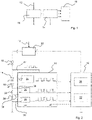
- FIG. 1 shows the basic idea of the invention in a highly schematic manner, according to which a string 10 of series-connected LEDs of a corresponding LED light module, in particular a light module for signal lights in road and rail traffic, is supplied with a current with a specific voltage in a manner known per se via a line 12 supplied and then part of the supplied current is used via a parallel to at least some of the LEDs of the strand circuit for operating a monitoring unit 14.
- the monitoring unit 14 can record certain operating parameters of the light module, such as the current flowing through the strand during operation, the voltage drop across the strand, the temperature in the vicinity of the strand and the luminous flux generated by the strand, and transmit values characteristic of these operating parameters to a higher-level system Output evaluation unit 16.
- the monitoring unit 14 can be fed completely via the power supply of the LED string, so that a separate power supply is advantageously dispensed with and, in particular when the light module is used in signal lights for rail traffic, considerable amounts of cable can sometimes be saved.
- Means such as voltmeters for the LED forward voltage can be provided connected in parallel to one or more LEDs 18 of the string 10 . During operation of the light module, these means can be supplied with power via the power supply 20 of the LEDs.
- the higher-level evaluation unit 16 is supplied via the power supply of the LED string, thus avoiding detection of scattered light when the LED string is switched off in pulses.
- the modern components required for this, such as temperature or photo sensors and microcontrollers, have such a low current consumption that there is no noticeable effect on the luminous flux of the LED string if part of the current to supply units 14 and 16 is branched off.
- an LED string 10 of the type in question for example, eight series-connected LEDs with a current consumption of 350 mA
- a Photo sensor as a means for detecting another operating parameter and a corresponding microcontroller for evaluating the signal of the photo sensor have a current consumption in the range of about 1 to 2 mA. It has been shown that a circuit according to the invention works particularly well when the current consumption of the units 14 and 16 is more than 20 times smaller than the current consumption of the LED string, preferably about 50 to 100 times smaller.
- the light module shown forms a unit that is installed in particular in a signal light and can be externally supplied with power via a line 12 .
- the LED string is formed by a number of series-connected LEDs 18, only a few of which are shown here, with the supply voltage and current being controlled by a ballast unit 20.
- the ballast unit 20, like the evaluation unit 16 is part of the light module, but, like the evaluation unit 16, can also be arranged outside of the actual light module.
- Evaluation unit 16 and upstream unit can be part of a single control unit.
- a monitoring unit 14 is supplied with current at a first point via a circuit parallel to the series connection of the LEDs 18, the various square-wave signals symbolically illustrated in the figure being intended to indicate that the current is pulse-width modulated.
- the monitoring unit 14 in this exemplary embodiment comprises a photo sensor 24 which is arranged in the light module and detects a value which is proportional to the luminous flux which is generated during operation of the LEDs.
- the LEDs are typically arranged rotationally symmetrically, and the light module is provided with an attachment or diffusing screen, as a result of which part of the emitted light is reflected back, which can then be detected by the photo sensor 24 .
- the monitoring unit 14 also includes two voltmeters 26 which, together with corresponding shunt resistors 28 and lines 30, enable an indirect current measurement of the current flowing through the LED string during operation.
- a voltmeter that measures the entire voltage drop across the LED string, which can be particularly advantageous in light modules for use in signal lights for rail traffic.
- the advantages of combined current-voltage monitoring when monitoring LED strings are well known and can be found, for example, in EP 1 992 524 A2 , the content of which is hereby incorporated by reference.
- means provided for detecting the current and/or the voltage can be supplied with current in a pulsed manner via the power supply of the LEDs.
- the values that are representative of the actual current, i.e. the current actually flowing through the LED string, from the voltmeters 26 and a value measured by the photo sensor 24 that is proportional to the luminous flux emitted during operation of the LEDs are fed to the evaluation unit 16, which is Embodiment includes a microcontroller 32 and a controller 34, which is designed to output a control value to the upstream unit 20. It should be noted that the evaluation unit 16 does not have its own power supply, as in previously known light modules, but is advantageously fed by the current supplied to the LEDs 18 in the same way as the monitoring unit 14 .
- the evaluation unit 16 can generate a corresponding control signal, by means of which the ballast unit 20 is prompted to increase the current supplied to the LEDs so that the desired luminous flux.
- the evaluation unit 16 is designed to control the current supplied to the LED string directly or indirectly as a function of the so-called “additional operating parameters”, i.e. here the luminous flux, i.e. either to influence the current directly as part of a more complex control circuit or to communicate with a separate unit, here the ballast unit 20, and to transmit this information that is the basis for controlling the current, and thus to control the current indirectly.
- additional operating parameters i.e. here the luminous flux
- the actual current detection has two channels and is therefore redundant, so that incorrect measurements are practically ruled out because the microcontroller 32 can be designed in such a way that it can generate a corresponding error message if there are deviations between the two signals that are representative of the actual current can then be transmitted in a manner known per se to a higher authority, for example a maintenance center.
- the pulse width modulated operation provided in a preferred embodiment of the invention has two further significant advantages.
- the means for detecting at least one further operating parameter has a photo sensor as in 2 include a complex calculation of the stray light component, since the sensor is only in operation due to the inventive supply via the LED current when the LEDs are switched on, in which case stray light components can be neglected.
- Light that falls on the sensor when the LEDs are switched off between two current pulses is not included in the usual summation by the sensor, so that advantageously inexpensive standard photo sensors, which sum light over a certain period of time to output a measured value, are used can become.
- evaluation unit 16 can check whether photo sensor 24 or voltmeter 26 is supplying signals during the time between two current pulses, from which a malfunction of the photo sensor and/or the voltmeter can be concluded and in a manner known per se way a corresponding error message can be generated.
- the evaluation unit 16 thus has a function for testing the means for detecting the at least one additional operating parameter. It is therefore checked whether the signals output by the ammeter and/or the photo sensor show a profile that corresponds to the profile of the pulse width modulated current.
- the temperature in the vicinity of the LEDs of the strand is recorded, with this value then being able to be used to switch on a fan, for example, via the evaluation unit.
- a fan can also advantageously be supplied with power via the operating current of the LEDs, since the fan only needs to have a low power in typical applications.
- the invention allows in a particularly simple and cost-effective manner for the first time the implementation of a particularly reliable monitoring of the correct functioning of an LED light module, since three different monitoring methods - monitoring the voltage drop across the LED strand, monitoring the current flowing through the strand and detecting a delivered Luminous flux of proportional value - can be combined.
Landscapes
- Circuit Arrangement For Electric Light Sources In General (AREA)
- Led Devices (AREA)
- Led Device Packages (AREA)
Claims (4)
- Module de lumière à DEL, en particulier pour des feux de signalisation du trafic routier et ferroviaire, comprenant- au moins une branche (10) de DELs (18) connectées en série- des moyens de surveillance (26, 28, 30) du courant traversant la branche en fonctionnement de la branche et/ou de la chute de tension au niveau de la branche,- une alimentation en courant (20) des DELs,- une unité de surveillance (14) comprenant des moyens destinés à détecter au moins un autre paramètre de fonctionnement des DELs, qui comprennent un capteur (24) pour détecter une valeur proportionnelle à un flux lumineux émis pendant le fonctionnement du module de lumière et pour délivrer un signal sur la base de la valeur, etune unité d'évaluation (16) qui est conçue pour commander par modulation d'impulsion en largeur, en fonction du signal, l'alimentation en courant (20) des DELs pour un courant amené à la branche de DEL,
caractérisé en ce quependant le fonctionnement du module de lumière, l'unité de surveillance (14) est également alimentée en courant via l'alimentation en courant (20) des DELs (18) conformément à la modulation d'impulsion en largeur. - Module de lumière à DEL selon la revendication 1, caractérisé en ce que l'unité d'évaluation (16) dispose d'une fonction pour tester les moyens de détection dudit au moins un autre paramètre de fonctionnement.
- Procédé destiné à faire fonctionner un module de lumière à DEL, en particulier pour des feux de signalisation du trafic routier et ferroviaire, dans lequel- le module de lumière dispose d'au moins une branche (10) de DELs (18) connectées en série,- le courant traversant la branche en fonctionnement et/ou la chute de tension au niveau de la branche sont surveillés,- un capteur (24) d'une unité de surveillance (14) sert à détecter une valeur proportionnelle à un flux lumineux émis pendant le fonctionnement du module de lumière et à délivrer un signal sur la base de la valeur à une unité d'évaluation (16) de niveau supérieur, etle courant amené à la branche en fonctionnement est commandé en fonction de la valeur par modulation d'impulsion en largeur de l'alimentation en courant des DELs,
caractérisé en ce quependant le fonctionnement du module de lumière, l'unité de surveillance (14) est également alimentée en courant via l'alimentation en courant des DELs conformément à la modulation d'impulsion en largeur. - Feu de signalisation, en particulier pour le trafic routier et ferroviaire, caractérisé en ce qu'il comprend un module de lumière à DEL selon la revendication 1 ou 2.
Priority Applications (2)
| Application Number | Priority Date | Filing Date | Title |
|---|---|---|---|
| RS20220947A RS63645B1 (sr) | 2014-12-23 | 2015-12-14 | Led svetlosni modul, signalno svetlo sa takvim svetlosnim modulom, kao i postupak rada takvog svetlosnog modula |
| HRP20221261TT HRP20221261T1 (hr) | 2014-12-23 | 2015-12-14 | Led svjetlosni modul, signalno svijetlo sa takvim svjetlosnim modulom, kao i postupak rada takvog svjetlosnog modula |
Applications Claiming Priority (1)
| Application Number | Priority Date | Filing Date | Title |
|---|---|---|---|
| DE102014119623.6A DE102014119623A1 (de) | 2014-12-23 | 2014-12-23 | LED-Lichtmodul, Signalleuchte mit einem solchen Lichtmodul sowie Verfahren zum Betreiben eines solchen Lichtmoduls |
Publications (3)
| Publication Number | Publication Date |
|---|---|
| EP3038433A2 EP3038433A2 (fr) | 2016-06-29 |
| EP3038433A3 EP3038433A3 (fr) | 2016-07-27 |
| EP3038433B1 true EP3038433B1 (fr) | 2022-07-13 |
Family
ID=54979405
Family Applications (1)
| Application Number | Title | Priority Date | Filing Date |
|---|---|---|---|
| EP15199957.0A Active EP3038433B1 (fr) | 2014-12-23 | 2015-12-14 | Module d'eclairage del, feu de signalisation comprenant un tel module d'eclairage et procede de fonctionnement d'un tel module d'eclairage |
Country Status (10)
| Country | Link |
|---|---|
| EP (1) | EP3038433B1 (fr) |
| DE (1) | DE102014119623A1 (fr) |
| DK (1) | DK3038433T3 (fr) |
| ES (1) | ES2928388T3 (fr) |
| HR (1) | HRP20221261T1 (fr) |
| HU (1) | HUE060173T2 (fr) |
| LT (1) | LT3038433T (fr) |
| PL (1) | PL3038433T3 (fr) |
| PT (1) | PT3038433T (fr) |
| RS (1) | RS63645B1 (fr) |
Families Citing this family (1)
| Publication number | Priority date | Publication date | Assignee | Title |
|---|---|---|---|---|
| EP4016495A1 (fr) * | 2020-12-18 | 2022-06-22 | Siemens Mobility GmbH | Procédé de diagnostic de commande |
Family Cites Families (13)
| Publication number | Priority date | Publication date | Assignee | Title |
|---|---|---|---|---|
| US5783909A (en) * | 1997-01-10 | 1998-07-21 | Relume Corporation | Maintaining LED luminous intensity |
| DE19754222A1 (de) | 1997-12-06 | 1999-06-10 | Volkswagen Ag | Vorrichtung zur Funktionskontrolle von Lumineszenzdioden |
| US7740371B1 (en) * | 1998-03-19 | 2010-06-22 | Charles A. Lemaire | Method and apparatus for pulsed L.E.D. illumination for a camera |
| ATE285103T1 (de) * | 1998-07-23 | 2005-01-15 | Siemens Ag | Lichtsignalanlage sowie verfahren zum überwachen der lichtsignalanlage |
| US6078148A (en) * | 1998-10-09 | 2000-06-20 | Relume Corporation | Transformer tap switching power supply for LED traffic signal |
| DE102005032719A1 (de) * | 2005-07-13 | 2007-01-25 | Siemens Ag | Lichtsignalanlage, insbesondere für den Straßenverkehr |
| JP4962939B2 (ja) | 2006-03-03 | 2012-06-27 | トヨタ自動車株式会社 | 車両および車両の情報機器 |
| JP5237266B2 (ja) * | 2006-05-31 | 2013-07-17 | クリー インコーポレイテッド | 色制御を持つ照明装置、および照明方法 |
| DE102007021836A1 (de) * | 2007-05-07 | 2008-11-20 | Pintsch Bamag Antriebs- Und Verkehrstechnik Gmbh | LED Anordnung für Lichtsignalgeber insbesondere für Bahnübergänge sowie Lichtsignalgeber insbesondere für Bahnübergänge mit einer solchen LED-Anordnung |
| CN101978782A (zh) * | 2008-03-17 | 2011-02-16 | 埃尔多实验室控股有限公司 | Led组件、led固定件、控制方法和软件程序 |
| DE102010013310B4 (de) * | 2010-03-29 | 2012-02-23 | Panasonic Electric Works Vossloh-Schwabe Gmbh | Betriebsschaltung zum Betreiben eines Lüfters für ein Leuchtmodul |
| DE102010026012A1 (de) * | 2010-06-29 | 2011-12-29 | Siemens Aktiengesellschaft | LED-Lichtsignal |
| EP2992395B1 (fr) * | 2013-04-30 | 2018-03-07 | Digital Lumens Incorporated | Fonctionnement de diodes électroluminescentes à basse température |
-
2014
- 2014-12-23 DE DE102014119623.6A patent/DE102014119623A1/de not_active Withdrawn
-
2015
- 2015-12-14 HR HRP20221261TT patent/HRP20221261T1/hr unknown
- 2015-12-14 PL PL15199957.0T patent/PL3038433T3/pl unknown
- 2015-12-14 DK DK15199957.0T patent/DK3038433T3/da active
- 2015-12-14 ES ES15199957T patent/ES2928388T3/es active Active
- 2015-12-14 EP EP15199957.0A patent/EP3038433B1/fr active Active
- 2015-12-14 HU HUE15199957A patent/HUE060173T2/hu unknown
- 2015-12-14 RS RS20220947A patent/RS63645B1/sr unknown
- 2015-12-14 PT PT151999570T patent/PT3038433T/pt unknown
- 2015-12-14 LT LTEP15199957.0T patent/LT3038433T/lt unknown
Also Published As
| Publication number | Publication date |
|---|---|
| LT3038433T (lt) | 2022-11-10 |
| RS63645B1 (sr) | 2022-10-31 |
| DE102014119623A1 (de) | 2016-06-23 |
| DK3038433T3 (da) | 2022-10-24 |
| PT3038433T (pt) | 2022-10-17 |
| ES2928388T3 (es) | 2022-11-17 |
| EP3038433A2 (fr) | 2016-06-29 |
| EP3038433A3 (fr) | 2016-07-27 |
| HRP20221261T1 (hr) | 2022-12-09 |
| PL3038433T3 (pl) | 2022-12-27 |
| HUE060173T2 (hu) | 2023-02-28 |
Similar Documents
| Publication | Publication Date | Title |
|---|---|---|
| EP1417864B1 (fr) | Signal lumineux destine a la commande du trafic et procede de controle du fonctionnement d'un tel signal | |
| DE102010005088A1 (de) | Lichtsignal | |
| DE102007018224A1 (de) | LED-Leuchte mit stabilisiertem Lichtstrom und stabilisierter Lichtfarbe | |
| EP2131628B1 (fr) | Emetteur de signal | |
| EP0974947B1 (fr) | Appareil de signalisation lumineuse et procédé de contrôle de l'appareil de signalisation | |
| EP2589264B1 (fr) | Signal lumineux led | |
| DE102005023295A1 (de) | Schaltung zur Ansteuerung und Überwachung eines Lichtsignals | |
| DE10227487A1 (de) | Beleuchtungsvorrichtung | |
| EP3038433B1 (fr) | Module d'eclairage del, feu de signalisation comprenant un tel module d'eclairage et procede de fonctionnement d'un tel module d'eclairage | |
| DE102006056148B4 (de) | Verfahren zur Funktionsüberwachung einer Lichtsignalanlage und Verkehrssteuerungs-Lichtsignalanlage | |
| EP2687418B1 (fr) | Signal de trajectoire à LED pour le transport ferroviaire et interface pour un tel signal de trajectoire à LED | |
| DE102014112175A1 (de) | Verfahren zum Betreiben einer optoelektronischen Baugruppe und optoelektronische Baugruppe | |
| WO2007036509A1 (fr) | Procede et dispositif pour surveiller le signal lumineux d'un element lumineux electro-optique, notamment d'une del haute intensite utilisee dans le trafic ferroviaire pour un signal ferroviaire sur | |
| WO2009034014A2 (fr) | Détection et compensation de défaillances de del dans de longues chaînes de del | |
| DE60302434T2 (de) | Erkennung von Anhängeranwesenheit und -typ durch Stromdetektion | |
| EP2710394B1 (fr) | Dispositif et procédé de contrôle d'état d'un constituant d'une installation | |
| EP2866524B1 (fr) | Système et procédé de surveillance de plusieurs rampes de DEL et éclairage à DEL doté d'un tel système | |
| EP3165053B1 (fr) | Dispositif et procédé pour contrôler un transmetteur de signal d'un feu de circulation comportant une diode électroluminescente | |
| EP3072775B1 (fr) | Procédé de réponse de l'éclairage d'une lampe de signal dans un signal du trafic sur un dispositif de surveillance | |
| EP1341402A2 (fr) | Dispositif d' éclairage à module-LED | |
| EP3787379A1 (fr) | Système et procédé de vérification du luminaire d'un point d'éclairage équipé d'au moins un moyen d'éclairage à led | |
| DE102014008421B4 (de) | LED-Leuchtvorrichtung | |
| DE102010012800A1 (de) | LED-Lichtsignal | |
| DE102013110003B3 (de) | LED-Leuchte mit einer Anordnung zur Überwachung von LEDs | |
| DE102006056147A1 (de) | Verfahren zur Funktionsüberwachung von lichtemittierenden Halbleiterbauelementen |
Legal Events
| Date | Code | Title | Description |
|---|---|---|---|
| PUAI | Public reference made under article 153(3) epc to a published international application that has entered the european phase |
Free format text: ORIGINAL CODE: 0009012 |
|
| PUAL | Search report despatched |
Free format text: ORIGINAL CODE: 0009013 |
|
| AK | Designated contracting states |
Kind code of ref document: A2 Designated state(s): AL AT BE BG CH CY CZ DE DK EE ES FI FR GB GR HR HU IE IS IT LI LT LU LV MC MK MT NL NO PL PT RO RS SE SI SK SM TR |
|
| AX | Request for extension of the european patent |
Extension state: BA ME |
|
| AK | Designated contracting states |
Kind code of ref document: A3 Designated state(s): AL AT BE BG CH CY CZ DE DK EE ES FI FR GB GR HR HU IE IS IT LI LT LU LV MC MK MT NL NO PL PT RO RS SE SI SK SM TR |
|
| AX | Request for extension of the european patent |
Extension state: BA ME |
|
| RIC1 | Information provided on ipc code assigned before grant |
Ipc: H05B 33/08 20060101AFI20160621BHEP |
|
| RIN1 | Information on inventor provided before grant (corrected) |
Inventor name: WENZLER, PATRICK Inventor name: DEPKE, JAN |
|
| RIN1 | Information on inventor provided before grant (corrected) |
Inventor name: DEPKE, JAN Inventor name: WENZLER, PATRICK |
|
| STAA | Information on the status of an ep patent application or granted ep patent |
Free format text: STATUS: REQUEST FOR EXAMINATION WAS MADE |
|
| 17P | Request for examination filed |
Effective date: 20161128 |
|
| RBV | Designated contracting states (corrected) |
Designated state(s): AL AT BE BG CH CY CZ DE DK EE ES FI FR GB GR HR HU IE IS IT LI LT LU LV MC MK MT NL NO PL PT RO RS SE SI SK SM TR |
|
| STAA | Information on the status of an ep patent application or granted ep patent |
Free format text: STATUS: EXAMINATION IS IN PROGRESS |
|
| 17Q | First examination report despatched |
Effective date: 20181102 |
|
| STAA | Information on the status of an ep patent application or granted ep patent |
Free format text: STATUS: EXAMINATION IS IN PROGRESS |
|
| RAP1 | Party data changed (applicant data changed or rights of an application transferred) |
Owner name: PINTSCH GMBH |
|
| STAA | Information on the status of an ep patent application or granted ep patent |
Free format text: STATUS: EXAMINATION IS IN PROGRESS |
|
| REG | Reference to a national code |
Ref country code: DE Ref legal event code: R079 Ref document number: 502015015953 Country of ref document: DE Free format text: PREVIOUS MAIN CLASS: H05B0033080000 Ipc: H05B0045120000 |
|
| GRAP | Despatch of communication of intention to grant a patent |
Free format text: ORIGINAL CODE: EPIDOSNIGR1 |
|
| STAA | Information on the status of an ep patent application or granted ep patent |
Free format text: STATUS: GRANT OF PATENT IS INTENDED |
|
| RIC1 | Information provided on ipc code assigned before grant |
Ipc: H05B 45/50 20220101ALI20220210BHEP Ipc: H05B 45/12 20200101AFI20220210BHEP |
|
| INTG | Intention to grant announced |
Effective date: 20220225 |
|
| GRAS | Grant fee paid |
Free format text: ORIGINAL CODE: EPIDOSNIGR3 |
|
| GRAA | (expected) grant |
Free format text: ORIGINAL CODE: 0009210 |
|
| STAA | Information on the status of an ep patent application or granted ep patent |
Free format text: STATUS: THE PATENT HAS BEEN GRANTED |
|
| AK | Designated contracting states |
Kind code of ref document: B1 Designated state(s): AL AT BE BG CH CY CZ DE DK EE ES FI FR GB GR HR HU IE IS IT LI LT LU LV MC MK MT NL NO PL PT RO RS SE SI SK SM TR |
|
| REG | Reference to a national code |
Ref country code: GB Ref legal event code: FG4D Free format text: NOT ENGLISH |
|
| REG | Reference to a national code |
Ref country code: CH Ref legal event code: EP |
|
| REG | Reference to a national code |
Ref country code: IE Ref legal event code: FG4D Free format text: LANGUAGE OF EP DOCUMENT: GERMAN |
|
| REG | Reference to a national code |
Ref country code: DE Ref legal event code: R096 Ref document number: 502015015953 Country of ref document: DE |
|
| REG | Reference to a national code |
Ref country code: AT Ref legal event code: REF Ref document number: 1504937 Country of ref document: AT Kind code of ref document: T Effective date: 20220815 |
|
| REG | Reference to a national code |
Ref country code: RO Ref legal event code: EPE |
|
| REG | Reference to a national code |
Ref country code: PT Ref legal event code: SC4A Ref document number: 3038433 Country of ref document: PT Date of ref document: 20221017 Kind code of ref document: T Free format text: AVAILABILITY OF NATIONAL TRANSLATION Effective date: 20221010 |
|
| REG | Reference to a national code |
Ref country code: FI Ref legal event code: FGE |
|
| REG | Reference to a national code |
Ref country code: DK Ref legal event code: T3 Effective date: 20221017 Ref country code: NO Ref legal event code: T2 Effective date: 20220713 |
|
| REG | Reference to a national code |
Ref country code: SE Ref legal event code: TRGR |
|
| REG | Reference to a national code |
Ref country code: NL Ref legal event code: FP |
|
| REG | Reference to a national code |
Ref country code: ES Ref legal event code: FG2A Ref document number: 2928388 Country of ref document: ES Kind code of ref document: T3 Effective date: 20221117 |
|
| REG | Reference to a national code |
Ref country code: GR Ref legal event code: EP Ref document number: 20220402041 Country of ref document: GR Effective date: 20221109 |
|
| REG | Reference to a national code |
Ref country code: SK Ref legal event code: T3 Ref document number: E 40659 Country of ref document: SK |
|
| REG | Reference to a national code |
Ref country code: HR Ref legal event code: T1PR Ref document number: P20221261 Country of ref document: HR |
|
| REG | Reference to a national code |
Ref country code: EE Ref legal event code: FG4A Ref document number: E022824 Country of ref document: EE Effective date: 20221013 |
|
| REG | Reference to a national code |
Ref country code: HR Ref legal event code: ODRP Ref document number: P20221261 Country of ref document: HR Payment date: 20221205 Year of fee payment: 8 |
|
| REG | Reference to a national code |
Ref country code: DE Ref legal event code: R082 Ref document number: 502015015953 Country of ref document: DE Representative=s name: MEISSNER BOLTE PATENTANWAELTE RECHTSANWAELTE P, DE |
|
| PG25 | Lapsed in a contracting state [announced via postgrant information from national office to epo] |
Ref country code: IS Free format text: LAPSE BECAUSE OF FAILURE TO SUBMIT A TRANSLATION OF THE DESCRIPTION OR TO PAY THE FEE WITHIN THE PRESCRIBED TIME-LIMIT Effective date: 20221113 |
|
| PGFP | Annual fee paid to national office [announced via postgrant information from national office to epo] |
Ref country code: GR Payment date: 20221219 Year of fee payment: 8 |
|
| REG | Reference to a national code |
Ref country code: HU Ref legal event code: AG4A Ref document number: E060173 Country of ref document: HU |
|
| REG | Reference to a national code |
Ref country code: DE Ref legal event code: R097 Ref document number: 502015015953 Country of ref document: DE |
|
| PG25 | Lapsed in a contracting state [announced via postgrant information from national office to epo] |
Ref country code: SM Free format text: LAPSE BECAUSE OF FAILURE TO SUBMIT A TRANSLATION OF THE DESCRIPTION OR TO PAY THE FEE WITHIN THE PRESCRIBED TIME-LIMIT Effective date: 20220713 |
|
| PLBE | No opposition filed within time limit |
Free format text: ORIGINAL CODE: 0009261 |
|
| STAA | Information on the status of an ep patent application or granted ep patent |
Free format text: STATUS: NO OPPOSITION FILED WITHIN TIME LIMIT |
|
| 26N | No opposition filed |
Effective date: 20230414 |
|
| PG25 | Lapsed in a contracting state [announced via postgrant information from national office to epo] |
Ref country code: AL Free format text: LAPSE BECAUSE OF FAILURE TO SUBMIT A TRANSLATION OF THE DESCRIPTION OR TO PAY THE FEE WITHIN THE PRESCRIBED TIME-LIMIT Effective date: 20220713 |
|
| P01 | Opt-out of the competence of the unified patent court (upc) registered |
Effective date: 20230601 |
|
| PG25 | Lapsed in a contracting state [announced via postgrant information from national office to epo] |
Ref country code: IE Free format text: LAPSE BECAUSE OF NON-PAYMENT OF DUE FEES Effective date: 20221214 |
|
| REG | Reference to a national code |
Ref country code: HR Ref legal event code: ODRP Ref document number: P20221261 Country of ref document: HR Payment date: 20231208 Year of fee payment: 9 |
|
| PGFP | Annual fee paid to national office [announced via postgrant information from national office to epo] |
Ref country code: SK Payment date: 20231212 Year of fee payment: 9 |
|
| PGFP | Annual fee paid to national office [announced via postgrant information from national office to epo] |
Ref country code: GB Payment date: 20231219 Year of fee payment: 9 |
|
| PGFP | Annual fee paid to national office [announced via postgrant information from national office to epo] |
Ref country code: TR Payment date: 20231211 Year of fee payment: 9 Ref country code: SI Payment date: 20231208 Year of fee payment: 9 Ref country code: SE Payment date: 20231222 Year of fee payment: 9 Ref country code: RS Payment date: 20231212 Year of fee payment: 9 Ref country code: RO Payment date: 20231213 Year of fee payment: 9 Ref country code: PT Payment date: 20231211 Year of fee payment: 9 Ref country code: NO Payment date: 20231219 Year of fee payment: 9 Ref country code: NL Payment date: 20231226 Year of fee payment: 9 Ref country code: LV Payment date: 20231221 Year of fee payment: 9 Ref country code: LU Payment date: 20231226 Year of fee payment: 9 Ref country code: LT Payment date: 20231208 Year of fee payment: 9 Ref country code: IT Payment date: 20231221 Year of fee payment: 9 Ref country code: HU Payment date: 20231212 Year of fee payment: 9 Ref country code: HR Payment date: 20231208 Year of fee payment: 9 Ref country code: FR Payment date: 20231226 Year of fee payment: 9 Ref country code: FI Payment date: 20231228 Year of fee payment: 9 Ref country code: EE Payment date: 20231219 Year of fee payment: 9 Ref country code: DK Payment date: 20231222 Year of fee payment: 9 Ref country code: CZ Payment date: 20231211 Year of fee payment: 9 Ref country code: BG Payment date: 20231220 Year of fee payment: 9 Ref country code: AT Payment date: 20231219 Year of fee payment: 9 |
|
| PGFP | Annual fee paid to national office [announced via postgrant information from national office to epo] |
Ref country code: PL Payment date: 20231211 Year of fee payment: 9 Ref country code: BE Payment date: 20231226 Year of fee payment: 9 |
|
| PGFP | Annual fee paid to national office [announced via postgrant information from national office to epo] |
Ref country code: ES Payment date: 20240118 Year of fee payment: 9 |
|
| PG25 | Lapsed in a contracting state [announced via postgrant information from national office to epo] |
Ref country code: CY Free format text: LAPSE BECAUSE OF FAILURE TO SUBMIT A TRANSLATION OF THE DESCRIPTION OR TO PAY THE FEE WITHIN THE PRESCRIBED TIME-LIMIT Effective date: 20220713 |
|
| PGFP | Annual fee paid to national office [announced via postgrant information from national office to epo] |
Ref country code: DE Payment date: 20231227 Year of fee payment: 9 Ref country code: CH Payment date: 20240102 Year of fee payment: 9 |