EP0974811B1 - Caméras numériques - Google Patents
Caméras numériques Download PDFInfo
- Publication number
- EP0974811B1 EP0974811B1 EP99304721A EP99304721A EP0974811B1 EP 0974811 B1 EP0974811 B1 EP 0974811B1 EP 99304721 A EP99304721 A EP 99304721A EP 99304721 A EP99304721 A EP 99304721A EP 0974811 B1 EP0974811 B1 EP 0974811B1
- Authority
- EP
- European Patent Office
- Prior art keywords
- document
- camera
- digital camera
- pattern
- orientation
- Prior art date
- Legal status (The legal status is an assumption and is not a legal conclusion. Google has not performed a legal analysis and makes no representation as to the accuracy of the status listed.)
- Expired - Lifetime
Links
Images
Classifications
-
- H—ELECTRICITY
- H04—ELECTRIC COMMUNICATION TECHNIQUE
- H04N—PICTORIAL COMMUNICATION, e.g. TELEVISION
- H04N1/00—Scanning, transmission or reproduction of documents or the like, e.g. facsimile transmission; Details thereof
- H04N1/04—Scanning arrangements, i.e. arrangements for the displacement of active reading or reproducing elements relative to the original or reproducing medium, or vice versa
- H04N1/19—Scanning arrangements, i.e. arrangements for the displacement of active reading or reproducing elements relative to the original or reproducing medium, or vice versa using multi-element arrays
- H04N1/195—Scanning arrangements, i.e. arrangements for the displacement of active reading or reproducing elements relative to the original or reproducing medium, or vice versa using multi-element arrays the array comprising a two-dimensional array or a combination of two-dimensional arrays
- H04N1/19594—Scanning arrangements, i.e. arrangements for the displacement of active reading or reproducing elements relative to the original or reproducing medium, or vice versa using multi-element arrays the array comprising a two-dimensional array or a combination of two-dimensional arrays using a television camera or a still video camera
-
- G—PHYSICS
- G01—MEASURING; TESTING
- G01B—MEASURING LENGTH, THICKNESS OR SIMILAR LINEAR DIMENSIONS; MEASURING ANGLES; MEASURING AREAS; MEASURING IRREGULARITIES OF SURFACES OR CONTOURS
- G01B11/00—Measuring arrangements characterised by the use of optical techniques
- G01B11/24—Measuring arrangements characterised by the use of optical techniques for measuring contours or curvatures
- G01B11/25—Measuring arrangements characterised by the use of optical techniques for measuring contours or curvatures by projecting a pattern, e.g. one or more lines, moiré fringes on the object
- G01B11/2513—Measuring arrangements characterised by the use of optical techniques for measuring contours or curvatures by projecting a pattern, e.g. one or more lines, moiré fringes on the object with several lines being projected in more than one direction, e.g. grids, patterns
-
- G—PHYSICS
- G01—MEASURING; TESTING
- G01B—MEASURING LENGTH, THICKNESS OR SIMILAR LINEAR DIMENSIONS; MEASURING ANGLES; MEASURING AREAS; MEASURING IRREGULARITIES OF SURFACES OR CONTOURS
- G01B11/00—Measuring arrangements characterised by the use of optical techniques
- G01B11/30—Measuring arrangements characterised by the use of optical techniques for measuring roughness or irregularity of surfaces
- G01B11/306—Measuring arrangements characterised by the use of optical techniques for measuring roughness or irregularity of surfaces for measuring evenness
-
- G—PHYSICS
- G06—COMPUTING; CALCULATING OR COUNTING
- G06T—IMAGE DATA PROCESSING OR GENERATION, IN GENERAL
- G06T7/00—Image analysis
- G06T7/50—Depth or shape recovery
- G06T7/521—Depth or shape recovery from laser ranging, e.g. using interferometry; from the projection of structured light
-
- H—ELECTRICITY
- H04—ELECTRIC COMMUNICATION TECHNIQUE
- H04N—PICTORIAL COMMUNICATION, e.g. TELEVISION
- H04N1/00—Scanning, transmission or reproduction of documents or the like, e.g. facsimile transmission; Details thereof
- H04N1/04—Scanning arrangements, i.e. arrangements for the displacement of active reading or reproducing elements relative to the original or reproducing medium, or vice versa
- H04N1/19—Scanning arrangements, i.e. arrangements for the displacement of active reading or reproducing elements relative to the original or reproducing medium, or vice versa using multi-element arrays
- H04N1/195—Scanning arrangements, i.e. arrangements for the displacement of active reading or reproducing elements relative to the original or reproducing medium, or vice versa using multi-element arrays the array comprising a two-dimensional array or a combination of two-dimensional arrays
-
- H—ELECTRICITY
- H04—ELECTRIC COMMUNICATION TECHNIQUE
- H04N—PICTORIAL COMMUNICATION, e.g. TELEVISION
- H04N2201/00—Indexing scheme relating to scanning, transmission or reproduction of documents or the like, and to details thereof
- H04N2201/04—Scanning arrangements
- H04N2201/0402—Arrangements not specific to a particular one of the scanning methods covered by groups H04N1/04 - H04N1/207
- H04N2201/043—Viewing the scanned area
-
- H—ELECTRICITY
- H04—ELECTRIC COMMUNICATION TECHNIQUE
- H04N—PICTORIAL COMMUNICATION, e.g. TELEVISION
- H04N2201/00—Indexing scheme relating to scanning, transmission or reproduction of documents or the like, and to details thereof
- H04N2201/04—Scanning arrangements
- H04N2201/0402—Arrangements not specific to a particular one of the scanning methods covered by groups H04N1/04 - H04N1/207
- H04N2201/0434—Arrangements not specific to a particular one of the scanning methods covered by groups H04N1/04 - H04N1/207 specially adapted for scanning pages of a book
-
- H—ELECTRICITY
- H04—ELECTRIC COMMUNICATION TECHNIQUE
- H04N—PICTORIAL COMMUNICATION, e.g. TELEVISION
- H04N2201/00—Indexing scheme relating to scanning, transmission or reproduction of documents or the like, and to details thereof
- H04N2201/04—Scanning arrangements
- H04N2201/0402—Arrangements not specific to a particular one of the scanning methods covered by groups H04N1/04 - H04N1/207
- H04N2201/0436—Scanning a picture-bearing surface lying face up on a support
-
- H—ELECTRICITY
- H04—ELECTRIC COMMUNICATION TECHNIQUE
- H04N—PICTORIAL COMMUNICATION, e.g. TELEVISION
- H04N2201/00—Indexing scheme relating to scanning, transmission or reproduction of documents or the like, and to details thereof
- H04N2201/04—Scanning arrangements
- H04N2201/047—Detection, control or error compensation of scanning velocity or position
- H04N2201/04701—Detection of scanning velocity or position
- H04N2201/04715—Detection of scanning velocity or position by detecting marks or the like, e.g. slits
- H04N2201/04717—Detection of scanning velocity or position by detecting marks or the like, e.g. slits on the scanned sheet, e.g. a reference sheet
-
- H—ELECTRICITY
- H04—ELECTRIC COMMUNICATION TECHNIQUE
- H04N—PICTORIAL COMMUNICATION, e.g. TELEVISION
- H04N2201/00—Indexing scheme relating to scanning, transmission or reproduction of documents or the like, and to details thereof
- H04N2201/04—Scanning arrangements
- H04N2201/047—Detection, control or error compensation of scanning velocity or position
- H04N2201/04701—Detection of scanning velocity or position
- H04N2201/04743—Detection of scanning velocity or position by detecting the image directly
-
- H—ELECTRICITY
- H04—ELECTRIC COMMUNICATION TECHNIQUE
- H04N—PICTORIAL COMMUNICATION, e.g. TELEVISION
- H04N2201/00—Indexing scheme relating to scanning, transmission or reproduction of documents or the like, and to details thereof
- H04N2201/04—Scanning arrangements
- H04N2201/047—Detection, control or error compensation of scanning velocity or position
- H04N2201/04701—Detection of scanning velocity or position
- H04N2201/04749—Detecting position relative to a gradient, e.g. using triangular-shaped masks, marks or gratings
Definitions
- the present invention relates generally to digital cameras, and more particularly, to a digital camera capturing technique for documents.
- Projecting one or more points onto an object and detecting the projected points using an autofocus detector is the basis of so-called active (but nonacoustic) autofocus mechanisms in typical point-and-shoot cameras.
- Cameras can reliably determine the focal distance to a small area on an object, but cannot determine if an object is imaged obliquely, as can be the case with handheld exposures of documents.
- Cameras can indicate to the user that an object is too close to focus upon, but do not indicate that the depth of focus is inadequate to image an entire object. Determining the adequacy of the depth of focus of an entire object represents a complex problem that is typically left to the user.
- manual procedures such as stopped-down viewfinder techniques used by skilled photographers, are very inconvenient and prone to error particularly in low-contrast situations in a stopped-down viewfinder.
- US-A-4, 111,557 discloses an arrangement for detecting departures of shape from an ideal shape of an object which is illuminated with a light pattern from a projection, the light pattern being scanned by a separate receiving unit connected to a computing unit.
- a handheld digital camera comprising emitter circuitry arranged to project a pattern on an object, and, fixed relative to the emitter circuitry, image sensor circuitry for detecting an orientation of the object relative to an optical axis of the digital camera by detecting the projected pattern and then capturing the object.
- Multiple beams of light may be emitted, and the beams are preferably parallel.
- the multiple beams of light may comprise infrared beams or diverging beams of light.
- the camera may store in a memory data that represents the orientation of the object and the planarity of the object.
- An image processor may determine a planarity of the object and the apparatus may further comprise a plurality of emitters, the plurality of emitters projecting the spot pattern on the object.
- the image sensor may comprise a plurality of CMOS sensors and/or logic means that processes the projected spot pattern to determine the planarity and/or the orientation of the object, wherein the object comprises a document.
- the image sensor may detect multiple beams of light projected on the object, wherein the object comprises a document, whereby the image processor analyses a detection of the multiple beams of light projected on the document to determine an orientation of the document, the planarity of the document, a curl of the document, and a distance of the document.
- a method for a handheld digital camera capturing technique for documents comprising: projecting a spot pattern on a document to be captured by the digital camera; detecting the projected spot pattern; analysing the projected spot pattern to determine an orientation of the document relative to an optical axis of the digital camera and a planarity of the document.
- Data representing the orientation and planarity of a document may be processed prior to capturing the document, whereby the image sensor captures the document in sharp focus and without geometric distortions. Multiple exposures of the document may be processed to capture portions of the document that are at multiple distances in sharp focus.
- the method may further comprise outputting a signal to indicate that the digital camera should be reoriented with respect to the document.
- the projected spot pattern may be analysed to determine a distance of the document from the digital camera.
- the present invention is incorporated into a digital camera to permit compensation to be performed for the following effects in the handheld capture of documents at close range:
- a typical active autofocus camera employs an infrared emitter and a photodetector arranged on either side of the optical axis. As the shutter release is pressed part-way, a highly-collimated IR beam is projected (usually as a vertical bar) on the subject, and the position of the beam is imaged on the detector. The measurement of range relies on parallax between the emitter and detector.
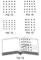
- the present invention involves projecting beams of visible or, preferably, infrared (IR) light on the document to be captured in a predetermined pattern (e.g., a spot pattern) as the shutter release is pressed part-way.
- a predetermined pattern e.g., a spot pattern
- the projected pattern is designed to provide information of range, orientation, and planarity of the document.
- the pattern is received by the image sensor in the digital camera and stored (or processed) immediately before the capture of the subject image using the image sensor.
- IR illumination provides an invisible measurement and uses the sensitivity of, for example, commercially available CCD and CMOS sensors to IR wavelengths.
- High intensity IR-LEDs are commercially available for use as emitters.
- a pattern to provide range and alignment can be provided by projecting three beams of light in a pattern. More robust patterns for measuring planarity of the subject can employ more than three beams of light, for example, to provide a grid of multiple cells.
- a method for a digital camera capturing technique includes determining an orientation of an object (e.g., a document) relative to an optical axis of the digital camera, and determining a distance of the object from the digital camera. The method also includes determining a planarity of the object. The method further includes projecting a pattern on the object, and detecting the projected pattern, which is then processed to determine the orientation of the object relative to the optical axis of the digital camera, the distance of the object from the digital camera, and the planarity of the object.
- an object e.g., a document
- the method also includes determining a planarity of the object.
- the method further includes projecting a pattern on the object, and detecting the projected pattern, which is then processed to determine the orientation of the object relative to the optical axis of the digital camera, the distance of the object from the digital camera, and the planarity of the object.
- the present invention provides a digital camera capturing technique for documents.
- the present invention uses projected beams of light (e.g., a spot pattern) and an image sensor of a digital camera to determine a distance, an orientation, and a planarity of an object to be captured. It is assumed that the spots are sharply imaged on the image sensor, which generally requires that the camera's autofocus system provide a useful, approximate focal distance measurement so that camera optics can be adjusted for optimal focus at close range. An object detected at close range automatically activates the document capture mode with its beam emissions and processing described herein. Measurement of the intensity distribution for each imaged spot provides an indication of the sharpness of focus and the usefulness of the spot for measurement purposes.
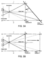
- the rotation of the plane is about an axis that is not perpendicular to the plane formed by beams 1 and 2.
- Some curvature of the object surface is allowed, for example, pages in a bound book and documents printed upon or wrapped around a cylinder.
- emitters 1A and 2A project beams 1 and 2 parallel to the optical axis.
- Object orientation A shows a plane rotated with respect to the optical axis (e.g., an oblique parallel projection).
- Beams 1 and 2 produce spots 1B and 2B, respectively.
- the images of spots 1B and 2B projected by the camera's lens onto its image sensor are 1C and 2C, respectively.
- the orientation and distance of the plane can be determined from the distances I-1C (the distance between two points A and B is denoted as A-B) and I-2C. These distances can be measured in pixels on the image sensor in the camera's image plane.
- the inequality of I-1C and I-2C indicates that the plane is pitched with respect to the optical axis.
- beams 1 and 2 When the plane is rotated to align its normal with the optical axis, beams 1 and 2 produce spots 1B and 2D, respectively, for example, in object orientation B, which are imaged as points 1C and 2E, respectively.
- I-1C and I-2E are identical, indicating alignment of the normal vector and the optical axis.
- FIG. 3b demonstrates distance measurement when the plane is perpendicular to the optical axis and translated between two positions (e.g., an orthographic parallel projection).
- position A beams 1 and 2 produce spots 1B and 2B on the object that are imaged as 1C and 2C, respectively.
- the distance to the object can be computed from I-1C and I-2C. Moving the object farther away, beams 1 and 2 produce spots 1D and 2D that are imaged as 1E and 2E, respectively. Because the distance I-1C is greater than I-1E, the object in position B is determined to be further away than the object in position A.
- An optimal focal distance for document capture can be computed from 1A-1B and 2A-2B taking into account the depth of field for the lens at its working aperture.
- the situation of a rotated object places demands on the camera's ability to deliver sharp focus across the document: for example, portions of the document may lie outside the camera's depth-of-focus.
- information obtained by the present invention can be used to make multiple exposures, each at different working distances, in order to capture the document piece-wise in sharp focus.
- the information that the camera's depth-of-focus is exceeded could be used to generate a signal to inform the user to reorient the camera with respect to the document.
- This information which typically cannot be determined from a single autofocus measurement at a point on a document, provides a valuable feature for opportunistic and casual capture of documents where precise alignment between the camera and the object cannot be or is not obtained.
- the angle ⁇ that the plane makes with the optical axis in object orientation A in FIG. 3a is arcsin (( 2A-2B - 1A-1B ) / 1A-2A ).
- FIGs. 3a and 3b and equations (1) - (4) show that, for parallel beams, it is desirable to maximize the offsets of the emitters from the optical axis (i.e., I-1A, I-2A) to achieve the maximum pixel count for I-1C and I-2C. Achieving the maximum pixel count for I-1C and I-2C provides the greatest resolution in equations (2b), (3), and (4) given the discrete number of pixels.
- Planarity e.g., distortion
- Planarity e.g., distortion
- Planarity e.g., distortion
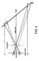
- FIG. 4 shows another embodiment in which emitters 3A and 4A are placed together on the optical axis and project a pattern using non-parallel (diverging) beams aimed toward the object.
- the non-parallel beams produce spots 3B and 4B on a rotated object.
- the images of these points at the camera's focal plane sensor are 3C and 4C, respectively.
- FIG. 4 illustrates the different results for parallel beams 1 and 2 and divergent beams 3 and 4. It is observed that the difference I-3C - I-4C is small for two significantly different distances 3A-3B and 4A-4B. This observation suggests that the co-located, diverging beam method has less sensitivity and greater susceptibility to discretization errors than the parallel beam method, where the difference I-1C - I-2C generally provides greater sensitivity.
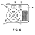
- FIG. 5 shows a digital camera 50 in accordance with one embodiment of the present invention.
- Digital camera 50 includes IR emitters 1A, 1A', 2A, and 2A' arranged around the optical axis of the camera's imaging system at a displacement that represents a reasonable compromise between usability and sensitivity.
- Digital camera 50 also includes an active autofocus emitter 51, a viewfinder 52, an autofocus detector 53, an orientation/range emitter 54, and an imaging lens 55.
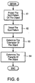
- FIG. 6 is a flow diagram of the operation of the digital camera of FIG. 5 in accordance with one embodiment of the present invention.
- digital camera 50 projects a spot pattern using IR emitters 1A, 1A', 2A, and 2A' to emit parallel IR beams on the object at stage 61.
- Digital camera 50 detects the spot pattern on its image sensor (see FIG. 7) at stage 62.
- Digital camera 50 determines the orientation of the object at stage 63, as discussed above with respect to FIGs. 3a and 3b.
- Digital camera 50 determines the planarity of the object at stage 64, as discussed above with respect to FIGs. 3a and 3b.
- Digital camera 50 can also determine the distance of the object from digital camera 50, as discussed above. Further, digital camera 50 can determine a (page) curl of the object, for example, in which the object is a document such as a page in a bound book.
- Digital camera 50 then processes this information accordingly, as discussed above with respect to FIGs. 3A and 3B.
- digital camera 50 can emit non-parallel beams of light and perform stages 63 and 64 as discussed above with respect to FIG. 4.
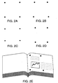
- output from orientation, planarity, and page curl determinations can be used by image processing algorithms to render a planar, undistorted image of a document captured obliquely and with page curl (e.g., a page of a bound book).
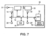
- FIG. 7 is a block diagram of the digital camera of FIG. 5 shown in greater detail in accordance with one embodiment of the present invention.
- digital camera 50 includes an ASIC 72 (Application Specific Integrated Circuit) that is in communication with orientation/range emitters 1A, 1A', 2A, and 2A', active autofocus emitter 51, viewfinder 52, autofocus detector 53, a memory 76 (e.g., a conventional random access memory that is used to store a captured digital image of a document) via a bus 74, and an image sensor 78 (e.g., a photodetector array that includes CMOS sensors for detecting IR light emitted from emitters 1A, 1A', 2A, and 2A').
- ASIC 72 Application Specific Integrated Circuit
- image sensor 78 which is used for image capture, is first used to acquire information relating to the distance, orientation, planarity, and curl of the document to be captured using the projected spot pattern (e.g., obtaining real-time information from a pre-exposure).
- ASIC 74 represents a main ASIC of the digital camera.
- ASIC 74 performs image processing.
- the image processing involved in the present invention can be implemented on image processing ASIC 74.
- the logic for performing the digital camera capturing technique can be implemented in a hardware description language, such as the VerilogTM hardware description language, described, for example, in D.E. Thomas, J.P. Moorby, "The VerilogTM. Hardware Description Language” (1991).
- the logic for performing the digital camera capturing technique can be implemented in the VerilogTM hardware description language, and the corresponding circuitry can be implemented using methods known in the art to provide an image processing ASIC for performing the digital camera capturing technique in accordance with one embodiment of the present invention (e.g., an ASIC implementation including logic that performs 3D geometrical transformations using a lookup table for inverse trigonometric calculations).
- the present invention includes the following:
- the present invention can be implemented in hardware or software or a combination of hardware and software.
- the present invention can also be implemented using any number and arrangement of orientation/range emitters providing a variety of spot patterns for image processing.
- the image sensor circuit can be implemented using CMOS sensors, CCD sensors, or other types of sensors that can detect a projected spot pattern. Therefore, the appended claims are to encompass within their scope all such changes and modifications that fall within the true scope of the present invention.
Claims (8)
- Appareil photo numérique de poche (50) comprenant un ensemble de circuits émetteurs (1A, 1A', 2A, 2A') agencés pour projeter une figure (1B, 2B) sur un objet et, fixé à l'ensemble de circuits émetteurs, un ensemble de circuits de détection d'image (78) pour détecter une orientation de l'objet par rapport à un axe optique de l'appareil photo numérique en détectant la figure projetée puis en capturant l'objet.
- Appareil photo selon la revendication 1 dans lequel l'ensemble de circuits de détection d'image est agencé pour détecter une planarité de l'objet.
- Appareil photo selon la revendication 1 dans lequel l'ensemble de circuits de détection d'image est agencé pour détecter une courbe d'un document.
- Appareil photo selon la revendication 3 comprenant en outre un ensemble de circuits de traitement d'image (74) agencé pour traiter une détection de la figure projetée pour déterminer l'orientation du document et la planarité du document.
- Appareil photo selon l'une quelconque des revendications précédentes, dans lequel l'ensemble de circuits émetteurs (1A, 1A', 2A, 2A') produit une figure projetée (1B, 2B) d'au moins quatre points projetés.
- Appareil photo selon l'une quelconque des revendications 1 à 4, dans lequel l'ensemble de circuits émetteurs (1A, 1A', 2A, 2A') produit une figure projetée comprenant de multiples faisceaux de lumière.
- Appareil photo selon l'une quelconque des revendications précédentes dans lequel l'ensemble de circuits émetteurs comprend une pluralité d'émetteurs (1A, 1A', 2A, 2A') et l'ensemble de circuits de détection d'image (78) réagit aux faisceaux traversant une lentille (55) de l'appareil photo, et dans lequel les émetteurs sont disposés autour du bord de la lentille.
- Procédé pour une technique de capture de documents d'un appareil photo numérique de poche (50), le procédé comprenant :la projection d'une figure de points (1B, 2B) sur un document à capturer par l'appareil photo numérique ;la détection de la figure de points projetée ;l'analyse de la figure de points projetée pour déterminer une orientation du document par rapport à un axe optique de l'appareil photo numérique et une planarité du document.
Applications Claiming Priority (2)
| Application Number | Priority Date | Filing Date | Title |
|---|---|---|---|
| US120096 | 1993-09-13 | ||
| US09/120,096 US6741279B1 (en) | 1998-07-21 | 1998-07-21 | System and method for capturing document orientation information with a digital camera |
Publications (2)
| Publication Number | Publication Date |
|---|---|
| EP0974811A1 EP0974811A1 (fr) | 2000-01-26 |
| EP0974811B1 true EP0974811B1 (fr) | 2004-11-03 |
Family
ID=22388244
Family Applications (1)
| Application Number | Title | Priority Date | Filing Date |
|---|---|---|---|
| EP99304721A Expired - Lifetime EP0974811B1 (fr) | 1998-07-21 | 1999-06-16 | Caméras numériques |
Country Status (4)
| Country | Link |
|---|---|
| US (1) | US6741279B1 (fr) |
| EP (1) | EP0974811B1 (fr) |
| JP (1) | JP2000089092A (fr) |
| DE (1) | DE69921559T2 (fr) |
Families Citing this family (30)
| Publication number | Priority date | Publication date | Assignee | Title |
|---|---|---|---|---|
| EP1067757A1 (fr) | 1999-07-09 | 2001-01-10 | Hewlett-Packard Company | Système d'imagerie pour des surfaces bouclées |
| EP1067362A1 (fr) | 1999-07-09 | 2001-01-10 | Hewlett-Packard Company | Système de formation d'images de documents |
| EP1128655B1 (fr) * | 2000-02-21 | 2006-12-06 | Hewlett-Packard Company, A Delaware Corporation | Cadre d'assistance pour appareils capteurs de documents |
| US6463220B1 (en) * | 2000-11-08 | 2002-10-08 | Xerox Corporation | Method and apparatus for indicating a field of view for a document camera |
| GB2372656A (en) * | 2001-02-23 | 2002-08-28 | Ind Control Systems Ltd | Optical position determination |
| GB2379818A (en) * | 2001-07-25 | 2003-03-19 | Univ Bristol | Automatic surface inspection using plural different radiation sources. |
| JP2003066321A (ja) | 2001-08-29 | 2003-03-05 | Mega Chips Corp | Af制御装置およびaf制御方法 |
| US7053939B2 (en) | 2001-10-17 | 2006-05-30 | Hewlett-Packard Development Company, L.P. | Automatic document detection method and system |
| FR2842591B1 (fr) * | 2002-07-16 | 2004-10-22 | Ecole Nale Sup Artes Metiers | Dispositif pour mesurer des variations dans le relief d'un objet |
| JP2004093275A (ja) | 2002-08-30 | 2004-03-25 | Seiko Precision Inc | 角度検出装置およびそれを備えたプロジェクタ |
| EP1426732A1 (fr) * | 2002-11-29 | 2004-06-09 | Seiko Precision Inc. | Dispositif de mesure d'angle, projecteur comprenant ce dispositif, et procédé de mesure d'angle |
| JP3874778B2 (ja) * | 2003-03-28 | 2007-01-31 | 富士通株式会社 | 撮影装置 |
| JP2005006228A (ja) * | 2003-06-13 | 2005-01-06 | Casio Comput Co Ltd | プロジェクタ |
| JP4155890B2 (ja) * | 2003-07-15 | 2008-09-24 | カシオ計算機株式会社 | プロジェクタ、プロジェクタの傾斜角度取得方法及び投影像補正方法 |
| JP3969363B2 (ja) * | 2003-07-30 | 2007-09-05 | カシオ計算機株式会社 | プロジェクタ及びプロジェクタの投影像補正方法 |
| JP4020043B2 (ja) * | 2003-08-25 | 2007-12-12 | カシオ計算機株式会社 | 投影装置、投影方法及びプログラム |
| JP4644540B2 (ja) | 2005-06-28 | 2011-03-02 | 富士通株式会社 | 撮像装置 |
| JP4799216B2 (ja) * | 2006-03-03 | 2011-10-26 | 富士通株式会社 | 距離測定機能を有する撮像装置 |
| WO2007112437A2 (fr) * | 2006-03-28 | 2007-10-04 | Axsun Technologies, Inc. | Système et procédé de spectroscopie raman à laser accordable et petit nombre de pixels |
| EP2053348A1 (fr) * | 2007-10-23 | 2009-04-29 | Texmag GmbH Vertriebsgesellschaft | Procédé et dispositif destinés à la saisie optique d'objets |
| US20110019243A1 (en) * | 2009-07-21 | 2011-01-27 | Constant Jr Henry J | Stereoscopic form reader |
| US8428394B2 (en) * | 2010-05-25 | 2013-04-23 | Marcus KRIETER | System and method for resolving spatial orientation using intelligent optical selectivity |
| DE112014007274T5 (de) * | 2014-12-19 | 2017-12-14 | Hewlett Packard Development Company, L.P. | Bestimmen von Positionsinformationen bei der Bilderfassung, basierend auf einem quasiperiodischen Muster |
| US10958841B2 (en) | 2017-01-06 | 2021-03-23 | Intel Corporation | Integrated image sensor and display pixel |
| JP2018117309A (ja) * | 2017-01-20 | 2018-07-26 | ソニーセミコンダクタソリューションズ株式会社 | 撮像装置、画像処理方法および画像処理システム |
| CN109445726B (zh) * | 2018-11-09 | 2021-11-23 | 珠海奔彩打印科技有限公司 | 一种多方向旋转编辑打印内容的打印装置及打印方法 |
| US10832045B2 (en) * | 2019-01-10 | 2020-11-10 | Microsoft Technology Licensing, Llc | Camera environment mapping |
| US11211433B2 (en) | 2020-05-04 | 2021-12-28 | Intel Corporation | In-display sensors and viewing angle adjustment microassemblies |
| US10991081B1 (en) | 2020-12-31 | 2021-04-27 | VoyagerX, Inc. | Book scanning using machine-trained model |
| US11030488B1 (en) | 2020-12-31 | 2021-06-08 | VoyagerX, Inc. | Book scanning using machine-trained model |
Family Cites Families (13)
| Publication number | Priority date | Publication date | Assignee | Title |
|---|---|---|---|---|
| DE2514930A1 (de) | 1975-04-05 | 1976-10-14 | Opto Produkte Ag | Verfahren zur optischen ermittlung und zum vergleich von formen und lagen von objekten |
| JPS60167069A (ja) * | 1984-02-09 | 1985-08-30 | Omron Tateisi Electronics Co | 図形認識装置 |
| US4914460A (en) | 1987-05-29 | 1990-04-03 | Harbor Branch Oceanographic Institution Inc. | Apparatus and methods of determining distance and orientation |
| EP0356680A1 (fr) * | 1988-08-11 | 1990-03-07 | Siemens Aktiengesellschaft | Appareil d'enregistrement optique pour système de traitement d'image |
| US6133951A (en) * | 1994-05-10 | 2000-10-17 | Asahi Kogaku Kogyo Kabushiki Kaisha | Still-video camera with function setting operation |
| US5793901A (en) * | 1994-09-30 | 1998-08-11 | Omron Corporation | Device and method to detect dislocation of object image data |
| JPH08336069A (ja) * | 1995-04-13 | 1996-12-17 | Eastman Kodak Co | 電子スチルカメラ |
| US5753931A (en) | 1995-07-13 | 1998-05-19 | Nike, Inc. | Object imaging device and method using line striping |
| US6034379A (en) * | 1996-03-01 | 2000-03-07 | Intermec Ip Corp. | Code reader having replaceable optics assemblies supporting multiple illuminators |
| US6003773A (en) * | 1996-03-01 | 1999-12-21 | Intermec Ip Corp. | Tablet style indicia reader with system for handling multiple indicia |
| US6449004B1 (en) * | 1996-04-23 | 2002-09-10 | Minolta Co., Ltd. | Electronic camera with oblique view correction |
| US6026186A (en) * | 1997-11-17 | 2000-02-15 | Xerox Corporation | Line and curve detection using local information |
| GB2359895B (en) * | 2000-03-03 | 2003-09-10 | Hewlett Packard Co | Camera projected viewfinder |
-
1998
- 1998-07-21 US US09/120,096 patent/US6741279B1/en not_active Expired - Lifetime
-
1999
- 1999-06-16 DE DE69921559T patent/DE69921559T2/de not_active Expired - Fee Related
- 1999-06-16 EP EP99304721A patent/EP0974811B1/fr not_active Expired - Lifetime
- 1999-07-15 JP JP11201278A patent/JP2000089092A/ja not_active Withdrawn
Also Published As
| Publication number | Publication date |
|---|---|
| US6741279B1 (en) | 2004-05-25 |
| DE69921559T2 (de) | 2005-10-27 |
| JP2000089092A (ja) | 2000-03-31 |
| EP0974811A1 (fr) | 2000-01-26 |
| DE69921559D1 (de) | 2004-12-09 |
Similar Documents
| Publication | Publication Date | Title |
|---|---|---|
| EP0974811B1 (fr) | Caméras numériques | |
| US11629955B2 (en) | Dual-resolution 3D scanner and method of using | |
| US9386299B2 (en) | Reference image techniques for three-dimensional sensing | |
| US6549288B1 (en) | Structured-light, triangulation-based three-dimensional digitizer | |
| US7123292B1 (en) | Mosaicing images with an offset lens | |
| AU2007254627B2 (en) | Geometric parameter measurement of an imaging device | |
| AU2016277593A1 (en) | Combined object capturing system and display device and associated method | |
| KR100481399B1 (ko) | 촬상 시스템, 상기 시스템에서 화상 데이터를 제어하도록사용되는 프로그램, 상기 시스템에서 촬상 화상의 왜곡을보정하기 위한 방법 및 상기 방법의 순서를 기억시키는기록 매체 | |
| US6424422B1 (en) | Three-dimensional input device | |
| AU2014208262A1 (en) | Apparatus and method for image super-resolution using integral shifting optics | |
| US20210150744A1 (en) | System and method for hybrid depth estimation | |
| US20240087167A1 (en) | Compensation of three-dimensional measuring instrument having an autofocus camera | |
| US10955236B2 (en) | Three-dimensional measuring system | |
| EP3988895B1 (fr) | Compensation d'un instrument de mesure tridimensionnel doté d'une caméra à mise au point automatique | |
| JPH1114327A (ja) | 3次元形状計測方法及びその装置 | |
| JPH05322526A (ja) | 3次元形状測定装置 | |
| Kainz et al. | Estimation of camera intrinsic matrix parameters and its utilization in the extraction of dimensional units | |
| CA2498484C (fr) | Detection et correction automatiques de perspective pour imagerie de document | |
| JP3583012B2 (ja) | フィルム傷検出装置 | |
| JPH06273211A (ja) | 非接触容積測定装置 | |
| JP2005092629A (ja) | 画像処理装置、及び、撮像装置 | |
| JP3527140B2 (ja) | 光ファイバガイドと光ファイバとの接続面角度位置決め方法およびその装置 | |
| JPH11104938A (ja) | 板金加工における画像処理方法およびその装置 | |
| JPH01235911A (ja) | 合焦位置検出方法 | |
| JP2003139518A (ja) | 画像入力光学系及び三次元形状測定装置 |
Legal Events
| Date | Code | Title | Description |
|---|---|---|---|
| PUAI | Public reference made under article 153(3) epc to a published international application that has entered the european phase |
Free format text: ORIGINAL CODE: 0009012 |
|
| AK | Designated contracting states |
Kind code of ref document: A1 Designated state(s): DE FR GB |
|
| AX | Request for extension of the european patent |
Free format text: AL;LT;LV;MK;RO;SI |
|
| 17P | Request for examination filed |
Effective date: 20000313 |
|
| AKX | Designation fees paid |
Free format text: DE FR GB |
|
| RAP1 | Party data changed (applicant data changed or rights of an application transferred) |
Owner name: HEWLETT-PACKARD COMPANY, A DELAWARE CORPORATION |
|
| 17Q | First examination report despatched |
Effective date: 20030729 |
|
| GRAP | Despatch of communication of intention to grant a patent |
Free format text: ORIGINAL CODE: EPIDOSNIGR1 |
|
| GRAS | Grant fee paid |
Free format text: ORIGINAL CODE: EPIDOSNIGR3 |
|
| GRAA | (expected) grant |
Free format text: ORIGINAL CODE: 0009210 |
|
| AK | Designated contracting states |
Kind code of ref document: B1 Designated state(s): DE FR GB |
|
| REG | Reference to a national code |
Ref country code: GB Ref legal event code: FG4D |
|
| REF | Corresponds to: |
Ref document number: 69921559 Country of ref document: DE Date of ref document: 20041209 Kind code of ref document: P |
|
| PLBE | No opposition filed within time limit |
Free format text: ORIGINAL CODE: 0009261 |
|
| STAA | Information on the status of an ep patent application or granted ep patent |
Free format text: STATUS: NO OPPOSITION FILED WITHIN TIME LIMIT |
|
| ET | Fr: translation filed | ||
| 26N | No opposition filed |
Effective date: 20050804 |
|
| PGFP | Annual fee paid to national office [announced via postgrant information from national office to epo] |
Ref country code: DE Payment date: 20070731 Year of fee payment: 9 |
|
| PGFP | Annual fee paid to national office [announced via postgrant information from national office to epo] |
Ref country code: GB Payment date: 20070628 Year of fee payment: 9 |
|
| PGFP | Annual fee paid to national office [announced via postgrant information from national office to epo] |
Ref country code: FR Payment date: 20070618 Year of fee payment: 9 |
|
| GBPC | Gb: european patent ceased through non-payment of renewal fee |
Effective date: 20080616 |
|
| REG | Reference to a national code |
Ref country code: FR Ref legal event code: ST Effective date: 20090228 |
|
| PG25 | Lapsed in a contracting state [announced via postgrant information from national office to epo] |
Ref country code: DE Free format text: LAPSE BECAUSE OF NON-PAYMENT OF DUE FEES Effective date: 20090101 |
|
| PG25 | Lapsed in a contracting state [announced via postgrant information from national office to epo] |
Ref country code: GB Free format text: LAPSE BECAUSE OF NON-PAYMENT OF DUE FEES Effective date: 20080616 |
|
| PG25 | Lapsed in a contracting state [announced via postgrant information from national office to epo] |
Ref country code: FR Free format text: LAPSE BECAUSE OF NON-PAYMENT OF DUE FEES Effective date: 20080630 |