EP0974790A2 - Système pour hottes aspirantes - Google Patents
Système pour hottes aspirantes Download PDFInfo
- Publication number
- EP0974790A2 EP0974790A2 EP99112427A EP99112427A EP0974790A2 EP 0974790 A2 EP0974790 A2 EP 0974790A2 EP 99112427 A EP99112427 A EP 99112427A EP 99112427 A EP99112427 A EP 99112427A EP 0974790 A2 EP0974790 A2 EP 0974790A2
- Authority
- EP
- European Patent Office
- Prior art keywords
- filter
- chimney pipe
- wall
- hood
- basic unit
- Prior art date
- Legal status (The legal status is an assumption and is not a legal conclusion. Google has not performed a legal analysis and makes no representation as to the accuracy of the status listed.)
- Granted
Links
Images


Classifications
-
- B—PERFORMING OPERATIONS; TRANSPORTING
- B08—CLEANING
- B08B—CLEANING IN GENERAL; PREVENTION OF FOULING IN GENERAL
- B08B15/00—Preventing escape of dirt or fumes from the area where they are produced; Collecting or removing dirt or fumes from that area
- B08B15/02—Preventing escape of dirt or fumes from the area where they are produced; Collecting or removing dirt or fumes from that area using chambers or hoods covering the area
-
- F—MECHANICAL ENGINEERING; LIGHTING; HEATING; WEAPONS; BLASTING
- F24—HEATING; RANGES; VENTILATING
- F24C—DOMESTIC STOVES OR RANGES ; DETAILS OF DOMESTIC STOVES OR RANGES, OF GENERAL APPLICATION
- F24C15/00—Details
- F24C15/20—Removing cooking fumes
-
- F—MECHANICAL ENGINEERING; LIGHTING; HEATING; WEAPONS; BLASTING
- F24—HEATING; RANGES; VENTILATING
- F24C—DOMESTIC STOVES OR RANGES ; DETAILS OF DOMESTIC STOVES OR RANGES, OF GENERAL APPLICATION
- F24C15/00—Details
- F24C15/20—Removing cooking fumes
- F24C15/2035—Arrangement or mounting of filters
Definitions
- the invention relates to an extractor hood system according to the preamble of Claim 1.
- cooker hoods Device types and sizes individually designed and constructed i.e. that the active parts of the extractor hood are adjusted to the respective device type and for these respective device types are manufactured.
- a device type becomes independent constructed by another type of device, the installation of the motor, the wiring of the Electronics, the switching and control of the device are based on the respective Device type based, etc.
- the object of the invention is to develop a system in which different Device types can be equipped with one and the same technology or basic unit, i.e. Extractor hoods of different sizes, different performance and different designs get a common basic unit, of which not active parts such as Panels, screen, etc. in freely selectable and can be put together.
- the same basic unit for different device types always has the same constructive structure and the same external dimensions and connections electrical and mechanical type, so that for different types of devices different vapors, chimney linings and decorative elements one and the same basic unit can be used, which is optional, for example with motors of different power or the like different design u. the like. Can be carried out.
- Extractor hood units as wall-mounted units or as stand-alone units, in exhaust air operation or in Recirculation mode is designed or for which engine power the device is to be designed.
- the blower motor is in a motor housing, e.g. made of die-cast aluminum, housed, so that a low-vibration construction with low weight can be achieved.
- the air outlet has a backflow flap, and that The motor housing accommodates two fan wheels, which suck in the air on both sides.
- the motor housing and the motor connections are different Engine performance in one and for the different engine performance same motor housing used.
- the lighting device consists of one or more halogen lamps the chimney are inserted so that a complete illumination of the Work surface is ensured.
- the filter arrangement is preferably in the form of two planes Formed arrangements that are inclined; optionally the Filter arrangement can also be made in one piece, e.g. in the form of a cylinder, one Truncated cone, a cuboid, a pyramid, a truncated pyramid and the like.
- the metal grease filter elements are each equipped with an active carbon filter in parallel for recirculation mode assigned, which is not required for exhaust air operation. Both filter types are in a common bracket spaced from each other. Metal grease filter and Active carbon filter elements have the same effective area, so that the Air speed kept low and the effectiveness of the activated carbon filter improved becomes.
- the effective area of the filter elements is for different device types within the same size as the basic unit.
- the filter arrangement overall in the form of a cylinder, truncated cone, cuboid, pyramid, Be truncated pyramid or the like. That is, in the circumferential direction closed system within which the vapor trapping space is formed, which is tapered from bottom to top.
- the electronic control of the active parts of the basic unit is preferably carried out via remote control, e.g. via infrared control, so that an essential part of the There is no wiring.
- the device motor is in at least four stages regulated, the lighting is switched independently of the motor.
- automatic overrun is provided, which has a follow-up time in any stage from e.g. has ten minutes, so that after this time the motor and the Lighting is switched off automatically. Furthermore takes place after a fixed predefined operating time of the engine an indication of the filter cleaning requirement.
- the remote control device can be accommodated in a universal holder allows attachment to the device, to the wall or the like. Such a thing Remote control device works in a similar manner as a remote control device for a TV.
- the basic unit has a supporting frame, at the lower end of which one frame-shaped border is provided on which the vapor screen is suspended.
- the Chimney cladding preferably consists of two telescopically one inside the other sliding tubes to adjust the height of the cladding and thus the To achieve chimneys.
- the lower chimney pipe sits on the vapor screen and will carried by this.
- the upper pipe section of the chimney cladding is with the ceiling or the side wall of the room, while the lower section supports the the electrical connection devices, the control boards, the connecting cable for the electrical or electronic operation of the base unit, and the like.
- the connection cable is usually with a behind the fireplace cladding arranged socket connected, which is not visible from the outside.
- the base unit has a frame-shaped or rail-like holder on which the screen sits.
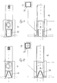
- the extractor hood according to the invention is schematically as Wall hood shown.
- An island hood is designed accordingly.
- the Overall hood is designated 1.
- a chimney cladding is shown.
- the Hood 1 is shown attached to the wall above a stove 3 with work surface 4.
- the chimney cladding 2 consists of telescopic tubes 5 and 6, with which the Working height of the device can be adjusted.
- a basic unit or technical unit 7 which is shown as a load-bearing Unit is formed and at the lower end a bracket 8 for receiving the Vapor umbrella owns.
- Lighting device 12 e.g. a radiator in the central axis 13 of the device arranged, which illuminates the work surface 4 with a light cone 14.
- 15 and 16 each represent filter arrangements in the form of metal filter plates that are more integral Are part of the basic unit 7 and define a vapor trapping room.
- the Filter arrangements 15, 16 arranged in a pitched roof are converted into corresponding ones Holding rails inserted.
- Control handles 17 are for inserting and removing the Plate filter provided.
- the lower edge of the basic unit is with a frame part 18 edged, which receives the vapor screen 19.
- the screen 19 is preferred hung on the frame-shaped bracket 18.
- the fireplace cover 2 is on the Fume screen 19 placed and is also carried by the bracket 18.
- FIGS 3 and 4 show the base unit 7 in an enlarged view. Out of this are the two filter assemblies 15 and 16 and their holder within the Basic unit shown in more detail.
- Each of the bilateral filter arrangements consists of a metal grease filter element 15b, 16b and one required for air recirculation Active carbon filter element 15a, 16a.
- the filter elements are in the form of plate filters trained, the metal grease filter elements are made of anodized aluminum.
- the Top of the filter elements is in profile rail sections 20, 21; 20 ', 21' fixed, the underside in corresponding profile rail sections 22, 23; 22 ', 23', whereby the Fixing the filter elements in these profile rail sections by clipping them in, Pinching, snapping or the like. Is carried out in a conventional manner.
- the Profile rail sections 20, 21; 20 ', 21' are part of a profile beam 24, the one represents open housing for receiving the lighting 12, while the profile rail sections 22, 23; 22 ', 23' each part of a profile rail 25 ' which, on the one hand, form the lower frame boundary of the basic unit 7, on the other hand form the receptacle for the lower section 6 of the chimney casing and at the same time serve as a support for the screen 19.
- Figures 5 and 6 show an embodiment of an extractor certain type of screen and chimney cladding, each in front view (Fig. 5a and 6a), in top view (FIGS. 5b and 6b) and in side view (FIGS. 5c and 6c).
- FIG. 7 and 8 a type of attachment of the base unit is in perspective and shown in sectional view.
- the holding frame 26 faces the wall of the room facing surface 27 on a mounting bracket 28, in which another Angle piece 29 is used, the one in the vertical web of the mounting bracket 28 guided adjusting screw 30 is adjustable.
- an adjusting screw 31 is provided, the height adjustment relative to Mounting bracket 28 allows. This is an adjustment of the hood possible both in the horizontal and in the vertical direction in an exact manner.
- FIG. 9 shows an extractor hood corresponding to the representation according to FIG. 3 in Front view, but with a filter arrangement 30 which is conical symmetrical to Chimney axis is formed and in which the lighting means 12 ', 12' (e.g. in the form of spotlights) are shown integrated in the screen.
- a filter arrangement 30 which is conical symmetrical to Chimney axis is formed and in which the lighting means 12 ', 12' (e.g. in the form of spotlights) are shown integrated in the screen.
- FIG. 10 shows a modified embodiment of a filter arrangement 31 in Truncated cone shape, namely Fig. 10a in front view, Fig. 10b in side view and Fig. 10c in a view from below.
- FIG. 11 Another embodiment of a filter arrangement 32 is shown in FIG. 11 in front view, Side view and view from below, the filter arrangement being tubular square cross-section is formed.
- the filter arrangement 33 is in the form of a Tätraederstumpfes trained.
- the filter arrangement 34 is as circular cylinder formed.
- FIG. 14 finally shows a filter arrangement in the form of a closed one Formed with a V-shaped cross section, the tip of which is curved, so that a cup shape 35 with a rounded bottom is formed.
- the curved top Portion of this filter assembly directs the air passing through the filter assembly the blower.
Landscapes
- Engineering & Computer Science (AREA)
- Chemical & Material Sciences (AREA)
- Combustion & Propulsion (AREA)
- Mechanical Engineering (AREA)
- General Engineering & Computer Science (AREA)
- Ventilation (AREA)
- Filtering Of Dispersed Particles In Gases (AREA)
- Arrangement Of Elements, Cooling, Sealing, Or The Like Of Lighting Devices (AREA)
Applications Claiming Priority (4)
| Application Number | Priority Date | Filing Date | Title |
|---|---|---|---|
| DE19832400 | 1998-07-18 | ||
| DE19832400 | 1998-07-18 | ||
| DE19838648A DE19838648B4 (de) | 1998-07-18 | 1998-08-25 | Dunstabzugshauben-System |
| DE19838648 | 1998-08-25 |
Publications (3)
| Publication Number | Publication Date |
|---|---|
| EP0974790A2 true EP0974790A2 (fr) | 2000-01-26 |
| EP0974790A3 EP0974790A3 (fr) | 2000-11-08 |
| EP0974790B1 EP0974790B1 (fr) | 2004-05-26 |
Family
ID=26047531
Family Applications (1)
| Application Number | Title | Priority Date | Filing Date |
|---|---|---|---|
| EP99112427A Expired - Lifetime EP0974790B1 (fr) | 1998-07-18 | 1999-06-30 | Système pour hottes aspirantes |
Country Status (4)
| Country | Link |
|---|---|
| EP (1) | EP0974790B1 (fr) |
| AT (1) | ATE267986T1 (fr) |
| DE (1) | DE29824156U1 (fr) |
| ES (1) | ES2221268T3 (fr) |
Cited By (10)
| Publication number | Priority date | Publication date | Assignee | Title |
|---|---|---|---|---|
| EP1177842A2 (fr) * | 2000-08-04 | 2002-02-06 | Sirius S.r.l. | Dispositif pour fixer des hottes d'aspiration au plafond |
| EP1251318A2 (fr) | 2001-04-18 | 2002-10-23 | Sino GmbH | Système pour hotte d'évacuation de fumées |
| DE102006008804A1 (de) * | 2006-02-25 | 2007-08-30 | O + F A-Line Gmbh | Dunsthaubenturm, Deckenrahmen zum Anschluss eines Dunsthaubenturmes, sowie Dunstabzugshaubeneinrichtung |
| EP2090835A2 (fr) * | 2008-02-14 | 2009-08-19 | Franke Futurum Aktiebolag | Hotte aspirante |
| EP2613096A1 (fr) * | 2012-01-05 | 2013-07-10 | V-Zug AG | Cheminée de ventilation domestique avec plaques de filtre parallèles |
| WO2014012470A1 (fr) * | 2012-07-18 | 2014-01-23 | 佛山市顺德区合捷电器实业有限公司 | Module de ventilation de hotte et méthode d'assemblage de celui-ci |
| EP1548368B1 (fr) * | 2003-10-21 | 2015-06-17 | BSH Hausgeräte GmbH | Ensemble de hottes de cuisine à tiroirs |
| CN105570946A (zh) * | 2015-10-16 | 2016-05-11 | 胡振强 | 高环保油烟处理机 |
| CN108019806A (zh) * | 2018-01-11 | 2018-05-11 | 广东美的厨房电器制造有限公司 | 吸油烟机 |
| WO2023148077A1 (fr) * | 2022-02-02 | 2023-08-10 | BSH Hausgeräte GmbH | Hotte aspirante |
Families Citing this family (3)
| Publication number | Priority date | Publication date | Assignee | Title |
|---|---|---|---|---|
| ITRN20060069A1 (it) * | 2006-10-30 | 2007-01-29 | Elica Spa | Struttura funzionale per cappe aspiranti |
| EP1918646A1 (fr) | 2006-10-30 | 2008-05-07 | Elica S.P.A. | Structure fonctionnelle pour capots d'extracteurs |
| DE102011080396A1 (de) * | 2011-08-04 | 2013-02-07 | BSH Bosch und Siemens Hausgeräte GmbH | Filterträger für Geruchsfilterelement und Dunstabzugshaube |
Citations (4)
| Publication number | Priority date | Publication date | Assignee | Title |
|---|---|---|---|---|
| US5209697A (en) * | 1992-02-10 | 1993-05-11 | Hurst Donald P | Blower system for a duct |
| EP0559038A2 (fr) * | 1992-03-06 | 1993-09-08 | Rolf Hertfelder | Installation de filtrage électrostatique pour hottes d'évacuation de vapeur |
| DE4403399A1 (de) * | 1994-02-04 | 1995-08-10 | Kueppersbusch | Dunstabzugshaube mit Fernsteuerempfänger |
| GB2296322A (en) * | 1994-12-22 | 1996-06-26 | Garland Commercial Ranges Ltd | Exhaust assembly for a cooking appliance |
-
1998
- 1998-08-25 DE DE29824156U patent/DE29824156U1/de not_active Expired - Lifetime
-
1999
- 1999-06-30 ES ES99112427T patent/ES2221268T3/es not_active Expired - Lifetime
- 1999-06-30 EP EP99112427A patent/EP0974790B1/fr not_active Expired - Lifetime
- 1999-06-30 AT AT99112427T patent/ATE267986T1/de not_active IP Right Cessation
Patent Citations (4)
| Publication number | Priority date | Publication date | Assignee | Title |
|---|---|---|---|---|
| US5209697A (en) * | 1992-02-10 | 1993-05-11 | Hurst Donald P | Blower system for a duct |
| EP0559038A2 (fr) * | 1992-03-06 | 1993-09-08 | Rolf Hertfelder | Installation de filtrage électrostatique pour hottes d'évacuation de vapeur |
| DE4403399A1 (de) * | 1994-02-04 | 1995-08-10 | Kueppersbusch | Dunstabzugshaube mit Fernsteuerempfänger |
| GB2296322A (en) * | 1994-12-22 | 1996-06-26 | Garland Commercial Ranges Ltd | Exhaust assembly for a cooking appliance |
Cited By (14)
| Publication number | Priority date | Publication date | Assignee | Title |
|---|---|---|---|---|
| EP1177842A2 (fr) * | 2000-08-04 | 2002-02-06 | Sirius S.r.l. | Dispositif pour fixer des hottes d'aspiration au plafond |
| EP1177842A3 (fr) * | 2000-08-04 | 2004-01-07 | Sirius S.r.l. | Dispositif pour fixer des hottes d'aspiration au plafond |
| EP1251318A2 (fr) | 2001-04-18 | 2002-10-23 | Sino GmbH | Système pour hotte d'évacuation de fumées |
| EP1251318A3 (fr) * | 2001-04-18 | 2004-03-03 | Sino GmbH | Système pour hotte d'évacuation de fumées |
| EP1548368B1 (fr) * | 2003-10-21 | 2015-06-17 | BSH Hausgeräte GmbH | Ensemble de hottes de cuisine à tiroirs |
| DE102006008804A1 (de) * | 2006-02-25 | 2007-08-30 | O + F A-Line Gmbh | Dunsthaubenturm, Deckenrahmen zum Anschluss eines Dunsthaubenturmes, sowie Dunstabzugshaubeneinrichtung |
| EP2090835A2 (fr) * | 2008-02-14 | 2009-08-19 | Franke Futurum Aktiebolag | Hotte aspirante |
| EP2090835A3 (fr) * | 2008-02-14 | 2011-05-04 | Franke Futurum Aktiebolag | Hotte aspirante |
| EP2613096A1 (fr) * | 2012-01-05 | 2013-07-10 | V-Zug AG | Cheminée de ventilation domestique avec plaques de filtre parallèles |
| WO2014012470A1 (fr) * | 2012-07-18 | 2014-01-23 | 佛山市顺德区合捷电器实业有限公司 | Module de ventilation de hotte et méthode d'assemblage de celui-ci |
| CN105570946A (zh) * | 2015-10-16 | 2016-05-11 | 胡振强 | 高环保油烟处理机 |
| CN105570946B (zh) * | 2015-10-16 | 2017-12-15 | 建湖县高新投资发展有限公司 | 环保油烟处理机 |
| CN108019806A (zh) * | 2018-01-11 | 2018-05-11 | 广东美的厨房电器制造有限公司 | 吸油烟机 |
| WO2023148077A1 (fr) * | 2022-02-02 | 2023-08-10 | BSH Hausgeräte GmbH | Hotte aspirante |
Also Published As
| Publication number | Publication date |
|---|---|
| DE29824156U1 (de) | 2000-08-10 |
| ATE267986T1 (de) | 2004-06-15 |
| EP0974790A3 (fr) | 2000-11-08 |
| ES2221268T3 (es) | 2004-12-16 |
| EP0974790B1 (fr) | 2004-05-26 |
Similar Documents
| Publication | Publication Date | Title |
|---|---|---|
| EP0974790B1 (fr) | Système pour hottes aspirantes | |
| DE10325004A1 (de) | Verbesserte Abzugshaube für eine freistehende Küchenzeile | |
| EP0241494B1 (fr) | Dispositif de chauffage uniforme de locaux | |
| DE4322662C2 (de) | Dunstabzugshaubenanordnung | |
| DE20005154U1 (de) | Dunstabzugshaube | |
| CH682512A5 (de) | Dampfabzugeinrichtung. | |
| EP0552686B1 (fr) | Dispositif d'aspiration à placer au-dessus du plan de cuisson d'une cuisinière | |
| EP1251318A2 (fr) | Système pour hotte d'évacuation de fumées | |
| DE19838648B4 (de) | Dunstabzugshauben-System | |
| DE212021000390U1 (de) | Beinanordnung für Tischreinigungsgerät | |
| EP2467649B1 (fr) | Hotte aspirante | |
| DE3436999A1 (de) | Dunstabzugsvorrichtung zur anordnung ueber dem kochfeld eines kuechenherdes o.dgl. | |
| EP2119971A2 (fr) | Hotte aspirante et filtre pour hotte aspirante | |
| EP0982548B1 (fr) | Système d'extraction en profilés | |
| EP0940634B1 (fr) | Hotte d'évacuation de fumée pour cuisine | |
| EP3170426A1 (fr) | Meuble de cuisine | |
| DE4415489C2 (de) | Dunstabzugsvorrichtung | |
| DE2613737B2 (de) | Luftreinigungsgerät, insbesondere über Küchenherden o.dgl. anzubringende Dunstabzugshaube | |
| DE19543113A1 (de) | Dunstabzugshaube für eine Haushaltsküche | |
| DE10000841B4 (de) | Dunstabzugshaube | |
| DE19739863C2 (de) | Dunstabzugshaube | |
| AT1117U1 (de) | Küchenanordnung | |
| EP2093501A2 (fr) | Dispositif d'aspiration de vapeur | |
| WO2009077284A2 (fr) | Hotte aspirante et filtre pour hotte aspirante | |
| DE1273162B (de) | Kuechendunstabzugsvorrichtung |
Legal Events
| Date | Code | Title | Description |
|---|---|---|---|
| PUAI | Public reference made under article 153(3) epc to a published international application that has entered the european phase |
Free format text: ORIGINAL CODE: 0009012 |
|
| AK | Designated contracting states |
Kind code of ref document: A2 Designated state(s): AT BE CH DE DK ES FR GB GR IT LI NL PT SE |
|
| AX | Request for extension of the european patent |
Free format text: AL;LT;LV;MK;RO;SI |
|
| PUAL | Search report despatched |
Free format text: ORIGINAL CODE: 0009013 |
|
| AK | Designated contracting states |
Kind code of ref document: A3 Designated state(s): AT BE CH CY DE DK ES FI FR GB GR IE IT LI LU MC NL PT SE |
|
| AX | Request for extension of the european patent |
Free format text: AL;LT;LV;MK;RO;SI |
|
| RAP1 | Party data changed (applicant data changed or rights of an application transferred) |
Owner name: SIRIUS S.R.L. |
|
| 17P | Request for examination filed |
Effective date: 20010316 |
|
| AKX | Designation fees paid |
Free format text: AT BE CH CY DE DK ES FI FR GB GR IE IT LI |
|
| RBV | Designated contracting states (corrected) |
Designated state(s): AT BE CH DE DK ES FR GB GR IT LI NL PT SE |
|
| 17Q | First examination report despatched |
Effective date: 20021111 |
|
| GRAP | Despatch of communication of intention to grant a patent |
Free format text: ORIGINAL CODE: EPIDOSNIGR1 |
|
| GRAS | Grant fee paid |
Free format text: ORIGINAL CODE: EPIDOSNIGR3 |
|
| GRAA | (expected) grant |
Free format text: ORIGINAL CODE: 0009210 |
|
| AK | Designated contracting states |
Kind code of ref document: B1 Designated state(s): AT BE CH DE DK ES FR GB GR IT LI NL PT SE |
|
| PG25 | Lapsed in a contracting state [announced via postgrant information from national office to epo] |
Ref country code: NL Free format text: LAPSE BECAUSE OF FAILURE TO SUBMIT A TRANSLATION OF THE DESCRIPTION OR TO PAY THE FEE WITHIN THE PRESCRIBED TIME-LIMIT Effective date: 20040526 |
|
| REG | Reference to a national code |
Ref country code: GB Ref legal event code: FG4D Free format text: NOT ENGLISH |
|
| REG | Reference to a national code |
Ref country code: CH Ref legal event code: EP |
|
| PGFP | Annual fee paid to national office [announced via postgrant information from national office to epo] |
Ref country code: CH Payment date: 20040611 Year of fee payment: 6 |
|
| PGFP | Annual fee paid to national office [announced via postgrant information from national office to epo] |
Ref country code: AT Payment date: 20040629 Year of fee payment: 6 |
|
| REF | Corresponds to: |
Ref document number: 59909565 Country of ref document: DE Date of ref document: 20040701 Kind code of ref document: P |
|
| PGFP | Annual fee paid to national office [announced via postgrant information from national office to epo] |
Ref country code: BE Payment date: 20040811 Year of fee payment: 6 |
|
| PG25 | Lapsed in a contracting state [announced via postgrant information from national office to epo] |
Ref country code: SE Free format text: LAPSE BECAUSE OF FAILURE TO SUBMIT A TRANSLATION OF THE DESCRIPTION OR TO PAY THE FEE WITHIN THE PRESCRIBED TIME-LIMIT Effective date: 20040826 Ref country code: GR Free format text: LAPSE BECAUSE OF FAILURE TO SUBMIT A TRANSLATION OF THE DESCRIPTION OR TO PAY THE FEE WITHIN THE PRESCRIBED TIME-LIMIT Effective date: 20040826 Ref country code: DK Free format text: LAPSE BECAUSE OF FAILURE TO SUBMIT A TRANSLATION OF THE DESCRIPTION OR TO PAY THE FEE WITHIN THE PRESCRIBED TIME-LIMIT Effective date: 20040826 |
|
| GBT | Gb: translation of ep patent filed (gb section 77(6)(a)/1977) |
Effective date: 20040906 |
|
| NLV1 | Nl: lapsed or annulled due to failure to fulfill the requirements of art. 29p and 29m of the patents act | ||
| RAP2 | Party data changed (patent owner data changed or rights of a patent transferred) |
Owner name: SIRIUS S.P.A. |
|
| REG | Reference to a national code |
Ref country code: ES Ref legal event code: FG2A Ref document number: 2221268 Country of ref document: ES Kind code of ref document: T3 |
|
| ET | Fr: translation filed | ||
| PLBE | No opposition filed within time limit |
Free format text: ORIGINAL CODE: 0009261 |
|
| STAA | Information on the status of an ep patent application or granted ep patent |
Free format text: STATUS: NO OPPOSITION FILED WITHIN TIME LIMIT |
|
| 26N | No opposition filed |
Effective date: 20050301 |
|
| PG25 | Lapsed in a contracting state [announced via postgrant information from national office to epo] |
Ref country code: LI Free format text: LAPSE BECAUSE OF NON-PAYMENT OF DUE FEES Effective date: 20050630 Ref country code: CH Free format text: LAPSE BECAUSE OF NON-PAYMENT OF DUE FEES Effective date: 20050630 Ref country code: BE Free format text: LAPSE BECAUSE OF NON-PAYMENT OF DUE FEES Effective date: 20050630 Ref country code: AT Free format text: LAPSE BECAUSE OF NON-PAYMENT OF DUE FEES Effective date: 20050630 |
|
| REG | Reference to a national code |
Ref country code: CH Ref legal event code: PL |
|
| BERE | Be: lapsed |
Owner name: *SIRIUS S.R.L. Effective date: 20050630 |
|
| PG25 | Lapsed in a contracting state [announced via postgrant information from national office to epo] |
Ref country code: PT Free format text: LAPSE BECAUSE OF NON-PAYMENT OF DUE FEES Effective date: 20041026 |
|
| PGFP | Annual fee paid to national office [announced via postgrant information from national office to epo] |
Ref country code: IT Payment date: 20080623 Year of fee payment: 10 |
|
| PGFP | Annual fee paid to national office [announced via postgrant information from national office to epo] |
Ref country code: ES Payment date: 20080627 Year of fee payment: 10 Ref country code: DE Payment date: 20080822 Year of fee payment: 10 |
|
| PGFP | Annual fee paid to national office [announced via postgrant information from national office to epo] |
Ref country code: FR Payment date: 20080630 Year of fee payment: 10 |
|
| PGFP | Annual fee paid to national office [announced via postgrant information from national office to epo] |
Ref country code: GB Payment date: 20080702 Year of fee payment: 10 |
|
| GBPC | Gb: european patent ceased through non-payment of renewal fee |
Effective date: 20090630 |
|
| REG | Reference to a national code |
Ref country code: FR Ref legal event code: ST Effective date: 20100226 |
|
| PG25 | Lapsed in a contracting state [announced via postgrant information from national office to epo] |
Ref country code: FR Free format text: LAPSE BECAUSE OF NON-PAYMENT OF DUE FEES Effective date: 20090630 |
|
| PG25 | Lapsed in a contracting state [announced via postgrant information from national office to epo] |
Ref country code: GB Free format text: LAPSE BECAUSE OF NON-PAYMENT OF DUE FEES Effective date: 20090630 |
|
| PG25 | Lapsed in a contracting state [announced via postgrant information from national office to epo] |
Ref country code: DE Free format text: LAPSE BECAUSE OF NON-PAYMENT OF DUE FEES Effective date: 20100101 |
|
| REG | Reference to a national code |
Ref country code: ES Ref legal event code: FD2A Effective date: 20090701 |
|
| PG25 | Lapsed in a contracting state [announced via postgrant information from national office to epo] |
Ref country code: ES Free format text: LAPSE BECAUSE OF NON-PAYMENT OF DUE FEES Effective date: 20090701 |
|
| PG25 | Lapsed in a contracting state [announced via postgrant information from national office to epo] |
Ref country code: IT Free format text: LAPSE BECAUSE OF NON-PAYMENT OF DUE FEES Effective date: 20090630 |