EP0974372A1 - Abdichtender Gummiverschluss für Spritze / Behälter - Google Patents
Abdichtender Gummiverschluss für Spritze / Behälter Download PDFInfo
- Publication number
- EP0974372A1 EP0974372A1 EP98113909A EP98113909A EP0974372A1 EP 0974372 A1 EP0974372 A1 EP 0974372A1 EP 98113909 A EP98113909 A EP 98113909A EP 98113909 A EP98113909 A EP 98113909A EP 0974372 A1 EP0974372 A1 EP 0974372A1
- Authority
- EP
- European Patent Office
- Prior art keywords
- luer
- nozzle
- rubber closure
- receiving part
- sealing rubber
- Prior art date
- Legal status (The legal status is an assumption and is not a legal conclusion. Google has not performed a legal analysis and makes no representation as to the accuracy of the status listed.)
- Granted
Links
Images

Classifications
-
- A—HUMAN NECESSITIES
- A61—MEDICAL OR VETERINARY SCIENCE; HYGIENE
- A61M—DEVICES FOR INTRODUCING MEDIA INTO, OR ONTO, THE BODY; DEVICES FOR TRANSDUCING BODY MEDIA OR FOR TAKING MEDIA FROM THE BODY; DEVICES FOR PRODUCING OR ENDING SLEEP OR STUPOR
- A61M5/00—Devices for bringing media into the body in a subcutaneous, intra-vascular or intramuscular way; Accessories therefor, e.g. filling or cleaning devices, arm-rests
- A61M5/178—Syringes
- A61M5/31—Details
- A61M5/3129—Syringe barrels
- A61M5/3134—Syringe barrels characterised by constructional features of the distal end, i.e. end closest to the tip of the needle cannula
-
- A—HUMAN NECESSITIES
- A61—MEDICAL OR VETERINARY SCIENCE; HYGIENE
- A61M—DEVICES FOR INTRODUCING MEDIA INTO, OR ONTO, THE BODY; DEVICES FOR TRANSDUCING BODY MEDIA OR FOR TAKING MEDIA FROM THE BODY; DEVICES FOR PRODUCING OR ENDING SLEEP OR STUPOR
- A61M5/00—Devices for bringing media into the body in a subcutaneous, intra-vascular or intramuscular way; Accessories therefor, e.g. filling or cleaning devices, arm-rests
- A61M5/178—Syringes
- A61M5/31—Details
- A61M2005/3103—Leak prevention means for distal end of syringes, i.e. syringe end for mounting a needle
- A61M2005/3104—Caps for syringes without needle
Definitions
- the present invention relates to a rubber-made sealing closure (which may also be called a "rubber cap” or “rubber closure”) adapted to be fitted on a liquid-medicine-injecting port (Luer nozzle) of a syringe/container with a medicament contained therein so that a solid or liquid injectable preparation contained as the medicament in the syringe/container can be sealed in place to maintain its quality over an extended period of time.
- the sealing closure has a plastic film laminated thereon at least at an area of an inner wall thereof, where the sealing closure is to be brought into or maintained in contact with the solid or liquid injectable preparation.
- rubber-made caps which are used with syringes as medical devices are different from sealing rubber closures employed with general containers for injectable preparations such as vials in that the sealing rubber closures normally remain in contact with liquid medicines (the Pharmacopoeia specifies certain quality standards required for the sealing rubber closures).
- Sealing rubber closures for syringe/containers with medicaments filled and sealed therein in advance are mostly made of a rubber material alone.
- An injectable liquid preparation which has been formulated in a form filled and sealed in a prefilled syringe, always remains in contact with a sealing rubber closure as opposed to an active ingredient in a medicinal preparation contained in a vial (a vessel of small capacity), so that the active ingredient in the injectable liquid preparation in the prefilled syringe tends to receive greater chemical influence from the rubber closure. From the standpoint of protection of the active ingredient from contamination, the conditions under which the active ingredient is placed are severe.
- JP kokai 7-313598 syringe-shaped container
- JP kokai 8-280800 prefilled syringe for two-part injectable preparation
- JP kokai 8-317975 prefilled syringe and a stopper assembly therefor
- EP 07 09 105A prefilled syringe and production process of the same.
- JP kokai 62-139668 laminated plug for syringe
- various examples of rubber-made sliding plugs (plungers) for prefilled syringes said plugs being laminated at surfaces thereof with tetrafluoroethylene-ethylene copolymer films
- a rubber plug for a front end portion of a syringe see Fig. 9 in the kokai publication; Fig. 2A in this application.
- the rubber plug for the front end portion of the syringe which is disclosed by way of example in the kokai publication, is indicated to be kept out of contact with a liquid medicine owing to the laminated film.
- Luer-nozzle-receiving part (a part in which a liquid-medicine-injecting port is inserted) is however configured in a substantially cylindrical, tapered form (i.e., the diameter on a side of an inner end portion is smaller than the diameter on a side of a Luer-nozzle-receiving opening). Accordingly, the Luer nozzle tends to fall out and sealing performance is hardly available, although the Luer-nozzle-receiving part is formed with an average outer diameter smaller than that of the associated Luer nozzle.
- the present inventors attempted to close a free end aperture of the Luer nozzle by forming the Luer-nozzle-receiving part of the rubber closure into an untapered cylindrical form (the diameter of which was smaller than the maximum diameter of the Luer nozzle) as shown in Fig. 2B and then forming a small bead on an inner end wall of the Luer-nozzle-receiving part as depicted in Fig. 2C.
- the insertion of the Luer nozzle was not smoothly performed and, when the Luer nozzle was inserted, wrinkles were developed in the laminated film, thereby failing to obtain satisfactory sealing performance.
- the conventionally proposed sealing rubber closures in which the front ends of syringes are to be inserted have fluorinated resin films laminated on inner walls thereof, so that the rubber closures are maintained out of direct contact with their corresponding liquid medicines. Since a fluorinated resin has high stiffness and can be hardly deformed, it must inherently apply high fastening force to the Luer nozzle inserted in the rubber closure.
- the inner wall of the rubber closure is formed in a substantially cylindrical form which has substantially the same taper as the Luer nozzle, and the fluorinated resin has small frictional resistance with other materials. Especially in the case of a plastic-made syringe, the inserted Luer nozzle therefore tends to slide.
- the rubber closure with the fluorinated resin film laminated thereon is inferior in sealing performance. Therefore, the rubber closure with the fluorinated resin film laminated thereon is not suited for practical use and requires improvements in sealing performance. If the Luer-nozzle-receiving part of the rubber closure is configured in an untapered cylindrical form, on the other hand, the Luer nozzle cannot be inserted smoothly, and wrinkles are hence formed in the laminated film, thereby failing to obtain satisfactory sealing performance.
- the present invention provides a sealing rubber closure for use with a prefilled syringe specified by ISO (the International Organization of Standardization) and having a Luer nozzle to be inserted into a Luer-nozzle-receiving part of the sealing rubber closure, wherein the Luer-nozzle-receiving part of the sealing rubber closure is configured, on a side of an inner end portion thereof, in an untapered cylindrical form to assure tight-fitted insertion of a free end portion of the Luer nozzle and, on a side of a Luer-nozzle-receiving opening thereof, in a tapered, substantially cylindrical form to assure tight-fitted insertion of a basal end portion of the Luer nozzle, and a plastic film is laminated on the sealing rubber closure at least in an area of the Luer-nozzle-receiving part, where a free end of the Luer nozzle is to be maintained in contact with the sealing rubber closure.
- ISO the International Organization of Standardization
- the present invention also provides a sealing rubber closure similar to the above-described sealing rubber closure, which is for use with a prefilled syringe specified by ISO (the International Organization of Standardization) and having a Luer nozzle and a Luer lock.
- ISO the International Organization of Standardization
- each of the sealing rubber closures in which a liquid-medicine-injecting portion such as the Luer nozzle of the prefilled syringe is to be inserted, can exhibit both excellent liquid leakproofness and superb gas sealing performance even when its receiving part, where the liquid-medicine-injecting portion is received, is laminated over the entire inner wall thereof with a plastic film.
- the sealing rubber closures according to the present invention can avoid any contact with a liquid medicine so that they do not give any adverse effects to the liquid medicine.
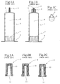
- FIG. 1A Schematic cross-sectional views of examples of syringe/containers (prefilled syringes) to which sealing rubber closures according to the present invention are applied are shown in Fig. 1A and Fig. 1B, respectively.
- the sealing rubber closures according to the present invention can be applied to a prefilled syringe provided with only a Luer nozzle 2 arranged as a liquid-medicine-injecting portion on a front end wall 5 of the prefilled syringe (Fig.
- a prefilled syringe provided on a front end wall 5 thereof with a Luer nozzle 2 and a Luer lock 3 for firmly fixing an extension tube, a three-way cock or the like on the prefilled syringe without becoming loose
- Fig. 1B, and Fig. 1C which is a perspective view of the Luer nozzle and Luer lock.
- These prefilled syringes are generally made of plastics.
- the shapes and dimensions of the Luer nozzle 2 and the Luer lock 3 in the prefilled syringes are specified by ISO Standards (for example, ISO 594-2, etc.).
- the Luer nozzle 2 which is arranged in the form of a hollow cylinder on the front end wall 5 of a syringe barrel 1 is configured to have an about 6/100 taper so that its outer diameter is smaller at a free end portion thereof than at a basal end portion thereof.
- the Luer lock 3 is in the form of a cylinder arranged concentrically on an outer side of the Luer nozzle 2 and has a helical groove (not shown) formed on an inner wall thereof.
- An injection needle or the like is screwed in a space 6 between the Luer nozzle 2 and the Luer lock 3 so that the injection needle or the like is maintained in engagement with the prefilled syringe.
- the length of the Luer nozzle 3, the length and inner diameter of the Luer lock 3, and the like are standardized by ISO.
- the Luer nozzle 2 is tapered on a peripheral wall thereof as described above.
- a Luer-nozzle-receiving part 11 is therefore configured in a substantially cylindrical form having a slight taper (its average bore diameter is smaller than an average outer diameter of the Luer nozzle), and is laminated with a plastic film 10 such as a fluorinated resin film to avoid any direct contact with a medicament.
- a fluorinated resin has higher stiffness and is hence more resistant to deformation. For its smaller frictional resistance with other materials, however, the tapered Luer nozzle inserted in the sealing rubber closure tends to fall out. It is therefore difficult to maintain sealing performance with a rubber closure laminated with a fluorinated resin film.
- the receiving part 11 is configured in an untapered cylindrical form having a diameter smaller than the average outer diameter of the Luer nozzle 2 with a view to assuring tight-fitted insertion of the Luer nozzle, the insertion of the Luer nozzle cannot be performed smoothly, resulting in the development of wrinkles in the laminated film and the failure to obtain sealing performance as described above.
- Each rubber closure according to the present invention for being fitted on a Luer nozzle of a prefilled syringe to seal the syringe (which will hereinafter be called simply a "rubber closure") can improve the above-described drawbacks of the conventional rubber closures.
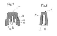
- a Luer-nozzle-receiving part of the rubber closure 9 is configured in an untapered cylindrical form on a side of an inner end portion thereof (in an upper portion thereof as viewed in the corresponding drawing) and in a tapered, substantially cylindrical form on a side of a Luer-nozzle-receiving opening thereof (in a lower portion thereof as viewed in the corresponding drawing).
- the diameter of the Luer-nozzle-receiving opening of the rubber closure 9 is greater than the outer diameter of the free end portion of the Luer nozzle, and the Luer-nozzle-receiving part is configured in the appropriately-tapered cylindrical form to a certain depth from the Luer-nozzle-receiving opening. Accordingly, the insertion of the Luer nozzle into the rubber closure can be performed easily and smoothly while avoiding development of wrinkles in the film laminated on the inner wall of the rubber closure. Further, the Luer-nozzle-receiving part is formed, on the side of the inner end portion thereof, in the untapered cylindrical form the inner diameter of which is smaller than the average outer diameter of the free end portion of the Luer nozzle. Excellent sealing performance can therefore be maintained.
- a Luer-nozzle-receiving part 11 of the rubber closure 9 is configured, on the side of its inner end portion (the portion above the broken line), in an untapered cylindrical form the diameter of which is smaller than the average outer diameter of the free end portion of the Luer nozzle, said free end portion being to be inserted in the inner end portion, so that the Luer nozzle can be inserted there in a tight-fitted manner.
- the remaining portion (the portion below the broken line) is configured in a tapered, substantially cylindrical form the average bore diameter of which is somewhat smaller than the average outer diameter of the remaining portion of the Luer nozzle, said remaining portion being to be inserted in the former remaining portion, for example, by about 5 to 30%.
- a plastic film 10 is laminated at least on the inner end wall of the Luer-nozzle-receiving part, with which the free end of the Luer nozzle will be maintained in contact. From the standpoint of the production of the rubber closure, it is generally preferred to laminate such a plastic film on the entire inner wall of the Luer-nozzle-receiving part. This will apply equally to the rubber closures according to the other embodiments of the present invention, which will be described subsequently herein.
- the inner diameter of the Luer-nozzle-receiving opening of the rubber closure according to the present invention is formed greater than the outer diameter of the free end of the Luer nozzle as described above, the insertion of the Luer nozzle into the Luer-nozzle-receiving opening can be facilitated and, when the Luer nozzle is inserted, no wrinkles are developed in the laminated film.
- the "tapered, substantially cylindrical form” can be embodied in two ways in the present invention, one being the case in which the difference between the bore diameter of the cylindrical Luer-nozzle-receiving part on the side of the inner end portion thereof and that of the Luer-nozzle-receiving part on the side of the Luer-nozzle-receiving opening thereof is small, and the other being the case in which the degree of tapering of the Luer-nozzle-receiving part on the side of the Luer-nozzle-receiving opening is set so that the space of the Luer-nozzle-receiving part takes the form of a combined shape of a frustum of a right circular cone and a right circular cylinder.
- the expression “tapered, substantially cylindrical form” is used in such a sense as embracing these two cases. This meaning will apply equally to the other rubber closures of the present invention to be described subsequently herein.
- the expression "tight-fitted insertion” as used herein means that, as is apparent from the foregoing description, an inserted Luer nozzle or, in the rubber closures of the other embodiments to be descried subsequent herein, an inserted Luer lock is firmly fastened by compressive force from a Luer-nozzle-receiving part or Luer-lock-receiving part. This meaning will apply equally to the other rubber closures of the present invention.
- the untapered cylindrical portion (the portion above the broken line in Fig. 3A or Fig. 3B) of the Luer-nozzle-receiving part 11 has dimensions (length or depth) sufficient to receive at least 30%, preferably 40 to 90%, more preferably 40 to 80% of the length of the Luer nozzle, and the remaining portion (the portion below the broken line in Fig. 3A or 3B) of the Luer-nozzle-receiving part 11 is formed in the tapered, substantially cylindrical form.
- the degree of tapering of the tapered portion of the Luer-nozzle-receiving part (the bore diameter of which is smaller on the side of the inner end portion than on the side of the Luer-nozzle-receiving opening), insofar as the insertion of the Luer nozzle is facilitated.
- the degree of tapering varies depending on the percentage of the Luer nozzle to be inserted in the Luer-nozzle-receiving part, the percentage of the tapered portion based on the Luer-nozzle-receiving part, the hardness and thickness of the rubber closure, and so on, and can be hardly determined in a wholesale manner.
- An optimal degree of tapering therefore, has to be determined by a trial and error method while taking these factors in consideration.
- the Luer-nozzle-receiving part of the rubber closure preferably a portion of the rubber closure, said portion extending to at least one fourth (1/4), more preferably from one third (1/3) to a half (1/2) of the overall length of the rubber closure from the lower end of the rubber closure, more resistant to deformation than the remaining portion thereof.
- each rubber closure No particular limitation is imposed on the external appearance or shape of each rubber closure according to the present invention, but a cylindrical or frustoconical (which means a frustum of a circular cone) shape is preferred from the standpoint of isotropically fastening a Luer nozzle inserted in its Luer-nozzle-receiving part.
- a cylindrical or frustoconical (which means a frustum of a circular cone) shape is preferred from the standpoint of isotropically fastening a Luer nozzle inserted in its Luer-nozzle-receiving part.
- the subsequent description on the wall thickness will be made based on these shapes.
- the preferred average wall thickness of the Luer-nozzle-receiving part 11 may range from 50 to 150% of the average outer diameter of the Luer nozzle, and the preferred average wall thickness of the Luer-nozzle-receiving part 11 on the side of the lower end of the rubber closure may be at least 10%, preferably 30 to 200%, more preferably 50 to 150% greater than the average wall thickness of the Luer-nozzle-receiving part.
- An increase in the wall thickness by less than 10% cannot bring about any substantial change in sealing performance.
- even an increase in the wall thickness by more than 200% cannot improve the sealing performance further so that such an excessively large wall thickness is not economical.
- the portion of such an increased wall thickness extends over the above-described range from the lower end of the rubber closure.
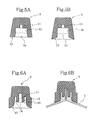
- an annular flange of a desired shape such as a semicircular or quadrilateral shape in cross-section may be formed as shown in Fig. 4A.
- the Luer-nozzle-receiving part may be provided with a similar bulged annular portion on the inner wall thereof at a location corresponding to the above-described annular flange.
- the wall thickness of the Luer-nozzle-receiving part as described above and further to control the hardness (JIS A hardness) of the rubber closure within a range of from 40 to 70, desirably from 55 to 70.
- the Luer-nozzle-receiving part 11 of the rubber closure is generally formed with a length (depth) sufficient to permit the insertion of 50% or more of the Luer nozzle.
- the Luer-nozzle-receiving opening (lower end) of the rubber closure is brought into contact at least at the inner peripheral edge portion thereof with the front end wall 5 of the prefilled syringe.
- the lower end of the rubber closure is generally configured in the form of a horizontal surface as depicted in Figs. 2A to 2C.
- the Luer-nozzle-receiving opening of the rubber closure into a shape (surface) complementary with the basal portion of the Luer nozzle or the surrounding front end wall (5 in Fig. 1B), with which the Luer-nozzle-receiving opening is to be brought into contact, as indicated at numeral 13 in Fig. 3B so that, when the Luer nozzle has been inserted, the lower end surface 13 can be maintained in close contact with the front end wall 5.
- the length (depth) of the Luer-nozzle-receiving part 11 of the rubber closure is dimensioned shorter (shallower) than the overall length of the Luer nozzle and the lower end of the Luer-nozzle-receiving part is configured in the form of a horizontal surface, it is preferred to provide the inner peripheral edge portion of the lower end of the rubber closure with an adequately rounded portion 13 (Fig. 3A) so that the insertion of the Luer nozzle can be facilitated.
- the rubber closures illustrated in Fig. 3A through Fig. 4B are examples of the construction that the Luer-nozzle-receiving part 11 of each rubber closure 9 is formed to a depth sufficient to receive the Luer nozzle over the entire length thereof and is configured in a untapered cylindrical form in a portion thereof extending over 60% the way down from the inner end portion thereof and in a tapered, substantially cylindrical form in the remaining portion thereof, the entire inner wall of the Luer-nozzle-receiving part and the peripheral edge wall of the Luer-nozzle-receiving opening are entirely laminated with a plastic film, and the Luer-nozzle-receiving opening of the rubber closure (see Fig. 3B, Fig. 4A and Fig.
- the wall thickness of the Luer-nozzle-receiving part is made greater within the above-descried range in a portion thereof extending over 40% the way up from the Luer-nozzle-receiving opening (the portions indicated at numeral 12 in Fig. 4A and Fig. 4B) than the remaining portion of the Luer-nozzle-receiving part.
- a receiving part of the rubber closure 9 is composed of a Luer-nozzle-receiving part 11 and a Luer-lock-receiving part 14.
- the Luer-nozzle-receiving part 11 has a depth sufficient to permit the insertion of the Luer nozzle over the entire length thereof (i.e., the entirety of the portion protruding from the free end of the Luer lock), and is configured in an untapered cylindrical form having a bore diameter smaller than the average outer diameter of the Luer nozzle at a corresponding location, for example, by about 5 to 30%.
- the Luer-lock-receiving part 14 is configured at a portion thereof, which extends over at least 10%, preferably 10 to 40% (to the extent up to the broken line) of the overall length of the Luer-lock-receiving part from a receiving opening of the receiving part of the rubber closure, in a tapered, substantially cylindrical form having an average bore diameter smaller than the outer diameter of the Luer lock to be inserted in the portion, for example, by about 5 to 30%.
- the remaining portion (the portion above the broken line) of the Luer-lock-receiving part is configured in an untapered cylindrical shape having a bore diameter smaller than the outer diameter of the Luer lock, for example, by about 5 to 30%.
- the outer diameter of the Luer lock is about 5 times as large as the average outer diameter of the Luer nozzle.
- the degree of the above-described tapering is set equal to or greater than the degree of tapering of the outer peripheral surface of the Luer nozzle, the insertion of the Luer lock is therefore hampered so that a laminated film 10 may be caused to develop wrinkles.
- no particular limitation is imposed on the degree of tapering insofar as it facilitates the insertion of the Luer lock into the Luer-lock-receiving part.
- the degree of tapering varies depending on the length of a portion which is provided with a taper. It is necessary to increase the degree of tapering as the length of the tapered portion becomes shorter. Further, the degree of tapering also varies depending on the hardness and wall thickness of the rubber closure, that is, the ease of deformation.
- An optimal degree of tapering which facilitates the insertion of the Luer lock into the receiving opening and also assures close contact with the Luer lock after the insertion, must be determined by a trial and error method while taking the above-described factors into consideration.
- the preferred wall thickness of the Luer-lock-receiving part 14 may be from 30 to 100%, more preferably from 40 to 80% of the outer diameter of the Luer lock. Due to the shape of the rubber closure according to the embodiment, the wall thickness of the Luer-nozzle-receiving part 11 unavoidably becomes substantially greater than the wall thickness of the Luer-lock-receiving part 14.
- the receiving part of the rubber closure according to this embodiment is laminated with the plastic film 10 at least in an area where the free end of the Luer nozzle is brought into contact with the rubber closure.
- Laminated locations are the same as those of the rubber closures described above.
- the lower end (receiving opening) 13 of the rubber closure is configured in the form of a horizontal surface.
- the peripheral edge portion of the Luer-lock-receiving opening of the rubber closure with an adequate rounded portion 13, for example, a rounded portion similar to the rounded portion in the vicinity of the basal portion of the Luer lock.
- Fig. 5B illustrates an example in which the Luer-lock-receiving part 14 is configured as a whole in an untapered cylindrical form.
- the Luer-lock-receiving part 14 extending preferably to at least one fourth (1/4), more preferably to one third (1/3) of the overall length of the rubber closure from the lower end of the rubber closure, more resistant to deformation than the remaining portion thereof.
- the wall thickness of the above-mentioned portion is greater by at least 5%, preferably 10 to 200%, more preferably 40 to 150% than the above-described average wall thickness of the Luer-lock-receiving part 14.
- An increase in the wall thickness by less than 5% cannot bring about any substantial improvement in sealing performance.
- even an increase in the wall thickness by more than 200% cannot bring about any additional improvement in sealing performance so that such an excessively large wall thickness is not economical.
- Fig. 6A and Fig. 6B further examples of rubber closures of this invention for use with prefilled syringes having Luer locks are illustrated in cross-section.
- a cylindrical ridge 15 is formed on the side of the inner end portion of the receiving part of a rubber closure 9.
- the cylindrical ridge is to be inserted in a tight-fitted state not only in a Luer-nozzle-receiving part 11 and a Luer-lock-receiving part 14 but also in an annular space (6 in Fig. 1B) between the Luer nozzle and the Luer lock.
- the rubber closure has the same structure as the rubber closure of Fig. 5A or Fig.
- the space of the Luer-lock-receiving part 14 can be configured in a partly-tapered cylindrical form as in Fig. 5A (Fig. 6A) or in a fully untapered cylindrical form as illustrated in Fig. 5B (Fig. 6B).
- the thickness of the cylindrical ridge 15, which is to be inserted in the annular space is greater, for example, by 5 to 20% than the average width of the annular space 6 of the prefilled syringe (see Fig. 1C).
- the height (length) of the cylindrical ridge 15 may be set at a value sufficient to reach the bottom of the annular space 6, or may be set at such a value that the cylindrical ridge extends only to an intermediate height of the annular space 6. In the latter case (Fig. 6B), it is preferred, for heightened sealing performance, to set the height (length) of the cylindrical ridge 15 at a value equivalent to at least 20% of the depth of the annular space 6.
- an inner peripheral edge portion of a Luer-lock-receiving opening with a rounded portion similar to that formed in the vicinity of the basal portion of the Luer nozzle so that the rubber closure can be maintained at the inner peripheral edge portion of the lower end thereof in close contact with a basal portion of the Luer lock.
- a rubber closure 9 of this embodiment which is for use with a prefilled syringe having a Luer nozzle and Luer lock to be inserted in the rubber closure, is configured, at a wall 13 surrounding a Luer-lock-receiving opening of a Luer-lock-receiving part 14 of the rubber closure, in a form maintainable in close contact with the basal portion of the Luer lock and a wall of the syringe, said wall surrounding the basal portion of the Luer lock, and the Luer-lock-receiving part 14 is configured as a whole in an untapered cylindrical form.
- a rubber closure 9 of this embodiment which is for use with a prefilled syringe having a Luer nozzle to be inserted in the rubber closure, is configured, at a wall 13 surrounding a Luer-nozzle-receiving opening of a Luer-nozzle-receiving part 11 of the rubber closure, in a form maintainable in close contact with the basal portion of the Luer nozzle and a wall of the syringe, said wall surrounding the basal portion of the Luer nozzle, and the Luer-nozzle-receiving part 11 is configured as a whole in an untapered cylindrical form.
- a plastic film is laminated on at least a portion of its Luer-nozzle-receiving part, which is adapted to receive a free end portion of a Luer nozzle of a prefilled syringe and may be brought into direct contact with a liquid medicine or the like filled in the prefilled syringe.
- No particular limitation is imposed on an area or areas to be laminated other than the above-described laminated portion.
- a plastic film may be laminated on the entire inner wall of the receiving part and/or on the peripheral edge portion 13 of the receiving opening.
- the above-described rubber closures of this invention can be produced using a rubber material, a vulcanizer and other additives, which have been used to date for the production of rubber closures for vials.
- the liquid medicine filled in the prefilled syringe and the rubber closure are prevented from undergoing direct contact owing to the provision of the plastic film, the liquid medicine is free from the potential danger that it could be contaminated by a substance eluted from the rubber closure. No limitation is therefore imposed on the kinds, amounts and the like of the rubber material and additives.
- the rubber material can include, but are not limited to, natural rubber (NR), polyisoprene rubber (IR), polybutadiene rubber (BR), styrenebutadiene copolymer rubber (SBR), butyl rubber (IIR), divinylbenzene-copolymerized butyl rubber (XL-IIR), chlorinated or brominated butyl rubber (Cl-IIR, Br-IIR), ethylene-propylene copolymer rubber (EPM), ethylene-propylene-diene monomer terpolymers (EPDMs), acrylonitrile-butadiene copolymer rubber (NBR), and hydrogenated NBR.
- natural rubber NR
- IR polyisoprene rubber
- BR polybutadiene rubber
- SBR styrenebutadiene copolymer rubber
- IIR butyl rubber
- XL-IIR divinylbenzene-copolymerized butyl rubber
- Illustrative of the additives are organic peroxide vulcanizer systems (organic peroxides, polyfunctional monomers, etc.), sulfur-containing vulcanizer systems (sulfur or sulfur-yielding compounds, zinc oxide, stearic acid, various vulcanization accelerators, etc.), reinforcing fillers, age resisters, and processing aids.
- organic peroxide vulcanizer systems organic peroxides, polyfunctional monomers, etc.
- sulfur-containing vulcanizer systems sulfur or sulfur-yielding compounds, zinc oxide, stearic acid, various vulcanization accelerators, etc.
- reinforcing fillers age resisters, and processing aids.
- a conventional mixer such as a roll mill, Banbury mixer or kneader, these additives and the above-described rubber material are combined into a rubber mix, which is then used for the production of rubber closures.
- plastic film can be used in the present invention insofar as it is inert to (is neither swollen by nor dissolved in) a liquid medicine filled in a prefilled syringe.
- plastics can include polyethylene (ordinary molecular weight to ultrahigh molecular weight), polypropylene, polycarbonates, polyesters, and fluorinated resins.
- fluorinated resins including, for example, polytetrafluoroethylene (PTFE), tetrafluoroethylene-ethylene copolymer (ETFE), tetrafluoroethylene-hexafluoropropylene copolymer (FEP), tetrafluoroethylene-fluoroalkyl vinyl ether copolymers (PFAs), polyfluorinated vinylidene (PVDF), and polychlorotrifluoroethylene (PCTFE).
- PTFE polytetrafluoroethylene
- ETFE tetrafluoroethylene-ethylene copolymer
- FEP tetrafluoroethylene-hexafluoropropylene copolymer
- PFAs tetrafluoroethylene-fluoroalkyl vinyl ether copolymers
- PVDF polyfluorinated vinylidene
- PCTFE polychlorotrifluoroethylene
- Each rubber closure according to the present invention is produced using the above-described mix rubber and plastic film, usually, by compression molding, but no particular limitation is imposed on its production method.
- compression molding for example, top and bottom mold members are used, which have been configured beforehand to define a predetermined shape therebetween.
- a mix rubber which is in the form of a sheet and carries one or more plastic films laminated thereon at predetermined areas thereof or over the entire surface thereof, is placed on the lower mold member. The laminate is compressed by the upper mold member and is then heated under elevated pressure to vulcanize the mix rubber, whereby a rubber closure is produced.
- Example or Comparative Example a rubber mix was prepared by mixing and kneading a rubber material and various additives in accordance with the corresponding formulation, which is shown in Table 1, by using a roll mill and an internal mixer.
- rubber closures for prefilled syringes were produced from this rubber mix and one or more fluorinated resin films (thickness: 50 ⁇ m, resin type: ETFE resin) by compression molding.
- each of the rubber closures was in a substantially cylindrical form having an average wall thickness of 4.2 mm, and was laminated with the fluorinated resin film at the entire inner wall(s) of its Luer-nozzle-receiving part or its Luer-nozzle-receiving part and Luer-lock-receiving part.
- non-laminated rubber closures were also produced likewise as shown in Table 2.
- the vulcanizing conditions were set at 150°C and 10 minutes.
- the sealing rubber closures of the present invention laminated on the entire inner walls of the receiving parts thereof are, different from the corresponding non-laminated rubber closures (Comparative Examples 1 and 2), not observed to have substantially affected the liquid medicine (the commercial water for injections was used as the liquid medicine) by their chemical components. It is therefore evident that the sealing rubber closures according to the present invention make it possible to minimize chemical influence which may be given to a medicament during a stability maintenance period (until a deadline for use). In this respect, the sealing rubber closures according to the present invention are the same as the conventional rubber closures having laminated films.
Landscapes
- Health & Medical Sciences (AREA)
- Vascular Medicine (AREA)
- Engineering & Computer Science (AREA)
- Anesthesiology (AREA)
- Biomedical Technology (AREA)
- Heart & Thoracic Surgery (AREA)
- Hematology (AREA)
- Life Sciences & Earth Sciences (AREA)
- Animal Behavior & Ethology (AREA)
- General Health & Medical Sciences (AREA)
- Public Health (AREA)
- Veterinary Medicine (AREA)
- Medical Preparation Storing Or Oral Administration Devices (AREA)
- Infusion, Injection, And Reservoir Apparatuses (AREA)
Priority Applications (8)
| Application Number | Priority Date | Filing Date | Title |
|---|---|---|---|
| JP07466497A JP3380705B2 (ja) | 1997-03-12 | 1997-03-12 | 注射器兼容器用密封ゴム栓 |
| US09/121,125 US20020022809A1 (en) | 1997-03-12 | 1998-07-23 | Sealing rubber closure for syringe/container |
| US09/121,125 US6344034B1 (en) | 1997-03-12 | 1998-07-23 | Sealing rubber closure for syringe/container |
| EP98113909A EP0974372B1 (de) | 1997-03-12 | 1998-07-24 | Abdichtender Gummiverschluss für Spritze / Behälter |
| DE69823987T DE69823987T2 (de) | 1998-07-24 | 1998-07-24 | Abdichtender Gummiverschluss für Spritze / Behälter |
| CA002243408A CA2243408C (en) | 1997-03-12 | 1998-07-24 | Sealing rubber closure for syringe/container |
| US09/641,894 US6524282B1 (en) | 1997-03-12 | 2000-08-18 | Sealing rubber closure for syringe/container |
| US10/314,234 US7214214B2 (en) | 1997-03-12 | 2002-12-09 | Sealing rubber closure for syringe/container |
Applications Claiming Priority (4)
| Application Number | Priority Date | Filing Date | Title |
|---|---|---|---|
| JP07466497A JP3380705B2 (ja) | 1997-03-12 | 1997-03-12 | 注射器兼容器用密封ゴム栓 |
| US09/121,125 US6344034B1 (en) | 1997-03-12 | 1998-07-23 | Sealing rubber closure for syringe/container |
| EP98113909A EP0974372B1 (de) | 1997-03-12 | 1998-07-24 | Abdichtender Gummiverschluss für Spritze / Behälter |
| CA002243408A CA2243408C (en) | 1997-03-12 | 1998-07-24 | Sealing rubber closure for syringe/container |
Publications (2)
| Publication Number | Publication Date |
|---|---|
| EP0974372A1 true EP0974372A1 (de) | 2000-01-26 |
| EP0974372B1 EP0974372B1 (de) | 2004-05-19 |
Family
ID=31982404
Family Applications (1)
| Application Number | Title | Priority Date | Filing Date |
|---|---|---|---|
| EP98113909A Expired - Lifetime EP0974372B1 (de) | 1997-03-12 | 1998-07-24 | Abdichtender Gummiverschluss für Spritze / Behälter |
Country Status (4)
| Country | Link |
|---|---|
| US (4) | US6344034B1 (de) |
| EP (1) | EP0974372B1 (de) |
| JP (1) | JP3380705B2 (de) |
| CA (1) | CA2243408C (de) |
Cited By (1)
| Publication number | Priority date | Publication date | Assignee | Title |
|---|---|---|---|---|
| US11013865B2 (en) | 2013-10-15 | 2021-05-25 | Becton Dickinson France | Tip cap assembly for closing an injection system |
Families Citing this family (55)
| Publication number | Priority date | Publication date | Assignee | Title |
|---|---|---|---|---|
| JP3380705B2 (ja) * | 1997-03-12 | 2003-02-24 | 株式会社大協精工 | 注射器兼容器用密封ゴム栓 |
| US7316669B2 (en) * | 2002-08-22 | 2008-01-08 | Baxa Corporation | Protective cap for medical male luer fittings |
| DE10238266A1 (de) * | 2002-02-28 | 2003-11-06 | Ibidi Gmbh | Mikrofluidsystem |
| US6821267B2 (en) * | 2002-03-07 | 2004-11-23 | Baxter International | Luer tip cap having reduced removal force |
| US20040028716A1 (en) * | 2002-06-14 | 2004-02-12 | Marks Andrew R. | Use of Y-27632 as an agent to prevent restenosis after coronary artery angioplasty/stent implantation |
| US20050010175A1 (en) * | 2003-02-27 | 2005-01-13 | Beedon Daniel E. | Piston assembly for syringe |
| JP4460278B2 (ja) * | 2003-12-17 | 2010-05-12 | 株式会社大協精工 | 注射器用密封栓及びプレフィルド注射器 |
| US8097225B2 (en) * | 2004-07-28 | 2012-01-17 | Honeywell International Inc. | Microfluidic cartridge with reservoirs for increased shelf life of installed reagents |
| US20060253103A1 (en) * | 2005-05-09 | 2006-11-09 | Utterberg David S | Removable cap needle access site |
| US8641684B2 (en) * | 2005-10-11 | 2014-02-04 | Nxstage Medical, Inc. | Closure for tubular access port |
| US8480968B2 (en) * | 2006-08-09 | 2013-07-09 | Lawrence Allan Lynn | Luer valve disinfectant swab-pouch |
| US20080039803A1 (en) * | 2006-08-09 | 2008-02-14 | Lawrence Allan Lynn | Luer protection pouch™ and luer valve/male luer protection method |
| US8361408B2 (en) * | 2006-03-16 | 2013-01-29 | Lawrence Allan Lynn | Luer protection pouch and luer valve/male luer protection method |
| US7794675B2 (en) | 2006-03-16 | 2010-09-14 | Lawrence Allan Lynn | Swab pouch |
| JP4843351B2 (ja) * | 2006-04-06 | 2011-12-21 | 株式会社大協精工 | ノズルキャップ、その製造方法および製造装置 |
| JP2008125560A (ja) * | 2006-11-16 | 2008-06-05 | Daikyo Seiko Ltd | 注射ノズルキャップ |
| EP3533481B1 (de) | 2007-02-27 | 2024-04-03 | DEKA Products Limited Partnership | Hämodialysesysteme |
| US9028691B2 (en) | 2007-02-27 | 2015-05-12 | Deka Products Limited Partnership | Blood circuit assembly for a hemodialysis system |
| US8336152B2 (en) | 2007-04-02 | 2012-12-25 | C. R. Bard, Inc. | Insert for a microbial scrubbing device |
| US9192449B2 (en) | 2007-04-02 | 2015-11-24 | C. R. Bard, Inc. | Medical component scrubbing device with detachable cap |
| EP3106189A1 (de) * | 2007-04-26 | 2016-12-21 | Daikyo Seiko, LTD. | Formgussverfahren für spritzenzylinder mit nadel und spritze mit nadel sowie form |
| AU2013204691B2 (en) * | 2007-10-12 | 2015-11-26 | Deka Products Limited Partnership | Apparatus and Methods for Hemodialysis |
| JP2011509803A (ja) | 2008-01-23 | 2011-03-31 | デカ・プロダクツ・リミテッド・パートナーシップ | 複数の流体ラインを使用した医療治療システムおよび方法 |
| US11833281B2 (en) | 2008-01-23 | 2023-12-05 | Deka Products Limited Partnership | Pump cassette and methods for use in medical treatment system using a plurality of fluid lines |
| US10201647B2 (en) | 2008-01-23 | 2019-02-12 | Deka Products Limited Partnership | Medical treatment system and methods using a plurality of fluid lines |
| DE102008013198B4 (de) * | 2008-03-07 | 2011-07-14 | Bayer Schering Pharma Aktiengesellschaft, 13353 | Originalitätsverschluss mit Haltezapfen |
| CN101983080B (zh) * | 2008-04-01 | 2013-12-25 | 生化学工业株式会社 | 药液排放部密封盖 |
| EP2332601A1 (de) * | 2008-08-25 | 2011-06-15 | Denki Kagaku Kogyo Kabushiki Kaisha | Spritze |
| PT2251453E (pt) | 2009-05-13 | 2014-03-13 | Sio2 Medical Products Inc | Retentor de vaso |
| US9458536B2 (en) | 2009-07-02 | 2016-10-04 | Sio2 Medical Products, Inc. | PECVD coating methods for capped syringes, cartridges and other articles |
| WO2011005801A1 (en) * | 2009-07-08 | 2011-01-13 | Speware Corporation | Luer seal for solid phase extraction columns |
| US8951229B2 (en) * | 2010-02-22 | 2015-02-10 | Boston Scientific Limited | Pressure actuated catheter seal and method for the same |
| US20120175368A1 (en) * | 2010-07-06 | 2012-07-12 | Speware Corporation | Luer seal for solid phase extraction columns |
| US8353869B2 (en) | 2010-11-02 | 2013-01-15 | Baxa Corporation | Anti-tampering apparatus and method for drug delivery devices |
| US9878101B2 (en) | 2010-11-12 | 2018-01-30 | Sio2 Medical Products, Inc. | Cyclic olefin polymer vessels and vessel coating methods |
| US9272095B2 (en) | 2011-04-01 | 2016-03-01 | Sio2 Medical Products, Inc. | Vessels, contact surfaces, and coating and inspection apparatus and methods |
| MX368025B (es) | 2011-05-24 | 2019-09-13 | Deka Products Lp | Sistema de hemodiálisis. |
| US10004854B2 (en) | 2012-03-07 | 2018-06-26 | West Pharmaceutical Services, Inc. | Low radial profile needle safety device |
| EP2822621B1 (de) | 2012-03-07 | 2016-09-21 | West Pharmaceutical Services, Inc. | Nadelschutzanordnung mit geringem radialen profil |
| US9791080B2 (en) | 2012-03-12 | 2017-10-17 | Idex Health & Science Llc | Microfluidic interconnect |
| JP5924113B2 (ja) * | 2012-05-15 | 2016-05-25 | 株式会社島津製作所 | ニードル洗浄機構 |
| WO2014071061A1 (en) | 2012-11-01 | 2014-05-08 | Sio2 Medical Products, Inc. | Coating inspection method |
| WO2014078666A1 (en) | 2012-11-16 | 2014-05-22 | Sio2 Medical Products, Inc. | Method and apparatus for detecting rapid barrier coating integrity characteristics |
| US9764093B2 (en) | 2012-11-30 | 2017-09-19 | Sio2 Medical Products, Inc. | Controlling the uniformity of PECVD deposition |
| WO2014085346A1 (en) | 2012-11-30 | 2014-06-05 | Sio2 Medical Products, Inc. | Hollow body with inside coating |
| US9662450B2 (en) | 2013-03-01 | 2017-05-30 | Sio2 Medical Products, Inc. | Plasma or CVD pre-treatment for lubricated pharmaceutical package, coating process and apparatus |
| CN105392916B (zh) | 2013-03-11 | 2019-03-08 | Sio2医药产品公司 | 涂布包装材料 |
| US9937099B2 (en) | 2013-03-11 | 2018-04-10 | Sio2 Medical Products, Inc. | Trilayer coated pharmaceutical packaging with low oxygen transmission rate |
| EP2971227B1 (de) | 2013-03-15 | 2017-11-15 | Si02 Medical Products, Inc. | Beschichtungsverfahren. |
| CN105188815B (zh) * | 2013-03-28 | 2019-08-06 | 拜耳医药保健有限公司 | 用于流体路径的无菌度增强的封闭 |
| KR20220093393A (ko) | 2013-12-06 | 2022-07-05 | 제넨테크, 인크. | 저체적 약품 전달을 위한 장치 및 방법 |
| US9440062B2 (en) | 2014-03-28 | 2016-09-13 | iMed Technology, Inc. | Medical site cover |
| JP6336879B2 (ja) * | 2014-10-07 | 2018-06-06 | 富士フイルム株式会社 | ゴム栓及びゴム栓の製造方法 |
| JP2016101240A (ja) * | 2014-11-27 | 2016-06-02 | 住友ゴム工業株式会社 | ノズルキャップおよびそのノズルキャップを使ったプレフィルドシリンジ |
| USD864385S1 (en) | 2017-07-13 | 2019-10-22 | iMed Technology, Inc. | Medical site cover mounting device |
Citations (8)
| Publication number | Priority date | Publication date | Assignee | Title |
|---|---|---|---|---|
| US4439184A (en) * | 1982-05-03 | 1984-03-27 | Concord Laboratories, Inc. | Two-dose syringe |
| JPS62139668A (ja) | 1985-12-16 | 1987-06-23 | 株式会社大協精工 | 積層した注射器用栓 |
| JPH07212598A (ja) | 1994-01-12 | 1995-08-11 | Toshiba Corp | 画像圧縮符号化装置 |
| EP0685237A2 (de) * | 1994-05-27 | 1995-12-06 | Nissho Corporation | Vorgefüllte Spritze |
| EP0709105A1 (de) | 1994-10-27 | 1996-05-01 | Schott Glaswerke | Vorfüllbare sterile partikelarme, sterile Einmalspritze für die Injektion von Präparaten und Verfahren zu ihrer Herstellung |
| US5531710A (en) * | 1995-02-24 | 1996-07-02 | Courtaulds Aerospace, Inc. | Combination closure and syringe |
| JPH08280800A (ja) | 1995-04-12 | 1996-10-29 | Nissho Corp | 2液注射用プレフィルドシリンジ |
| JPH08317975A (ja) | 1995-05-19 | 1996-12-03 | Becton Dickinson & Co | 予充填式注射器及びそのストッパーアッセンブリ |
Family Cites Families (14)
| Publication number | Priority date | Publication date | Assignee | Title |
|---|---|---|---|---|
| US2723041A (en) * | 1951-04-09 | 1955-11-08 | Hart-Still Sydney Charles | Closure for bottles and other containers |
| JPS56119254A (en) * | 1980-02-25 | 1981-09-18 | Takeda Chemical Industries Ltd | Rubber stopper for vial |
| US4390016A (en) * | 1981-10-23 | 1983-06-28 | Temp-Trak Inc. | Prefillable hypodermic syringe and method of assembling the syringe |
| EP0204486B1 (de) * | 1985-05-28 | 1990-10-17 | Daikyo Gomu Seiko Ltd. | Harzlaminierter Kunststoffstopfen und dessen Herstellung |
| US5184742A (en) * | 1990-06-18 | 1993-02-09 | Boc Health Care, Inc. | Deadender cap for luer fitting |
| US5125415A (en) * | 1990-06-19 | 1992-06-30 | Smiths Industries Medical Systems, Inc. | Syringe tip cap with self-sealing filter |
| US5498253A (en) * | 1993-11-23 | 1996-03-12 | Baxter International Inc. | Port adaptor and protector and container having same |
| AUPM922394A0 (en) * | 1994-11-03 | 1994-11-24 | Astra Pharmaceuticals Pty Ltd | Plastic syringe with overcap |
| US5624402A (en) * | 1994-12-12 | 1997-04-29 | Becton, Dickinson And Company | Syringe tip cap |
| US5954104A (en) * | 1997-02-28 | 1999-09-21 | Abbott Laboratories | Container cap assembly having an enclosed penetrator |
| JP3380705B2 (ja) * | 1997-03-12 | 2003-02-24 | 株式会社大協精工 | 注射器兼容器用密封ゴム栓 |
| US5902298A (en) * | 1997-11-07 | 1999-05-11 | Bracco Research Usa | Medicament container stopper with integral spike access means |
| US5921419A (en) * | 1998-05-04 | 1999-07-13 | Bracco Research Usa | Universal stopper |
| US6394983B1 (en) * | 1998-10-28 | 2002-05-28 | Abbott Laboratories | Cap and luer connector for a fluid transfer device |
-
1997
- 1997-03-12 JP JP07466497A patent/JP3380705B2/ja not_active Expired - Lifetime
-
1998
- 1998-07-23 US US09/121,125 patent/US6344034B1/en not_active Expired - Lifetime
- 1998-07-23 US US09/121,125 patent/US20020022809A1/en active Granted
- 1998-07-24 CA CA002243408A patent/CA2243408C/en not_active Expired - Lifetime
- 1998-07-24 EP EP98113909A patent/EP0974372B1/de not_active Expired - Lifetime
-
2000
- 2000-08-18 US US09/641,894 patent/US6524282B1/en not_active Expired - Lifetime
-
2002
- 2002-12-09 US US10/314,234 patent/US7214214B2/en not_active Expired - Lifetime
Patent Citations (8)
| Publication number | Priority date | Publication date | Assignee | Title |
|---|---|---|---|---|
| US4439184A (en) * | 1982-05-03 | 1984-03-27 | Concord Laboratories, Inc. | Two-dose syringe |
| JPS62139668A (ja) | 1985-12-16 | 1987-06-23 | 株式会社大協精工 | 積層した注射器用栓 |
| JPH07212598A (ja) | 1994-01-12 | 1995-08-11 | Toshiba Corp | 画像圧縮符号化装置 |
| EP0685237A2 (de) * | 1994-05-27 | 1995-12-06 | Nissho Corporation | Vorgefüllte Spritze |
| EP0709105A1 (de) | 1994-10-27 | 1996-05-01 | Schott Glaswerke | Vorfüllbare sterile partikelarme, sterile Einmalspritze für die Injektion von Präparaten und Verfahren zu ihrer Herstellung |
| US5531710A (en) * | 1995-02-24 | 1996-07-02 | Courtaulds Aerospace, Inc. | Combination closure and syringe |
| JPH08280800A (ja) | 1995-04-12 | 1996-10-29 | Nissho Corp | 2液注射用プレフィルドシリンジ |
| JPH08317975A (ja) | 1995-05-19 | 1996-12-03 | Becton Dickinson & Co | 予充填式注射器及びそのストッパーアッセンブリ |
Cited By (1)
| Publication number | Priority date | Publication date | Assignee | Title |
|---|---|---|---|---|
| US11013865B2 (en) | 2013-10-15 | 2021-05-25 | Becton Dickinson France | Tip cap assembly for closing an injection system |
Also Published As
| Publication number | Publication date |
|---|---|
| CA2243408A1 (en) | 2000-01-24 |
| JP3380705B2 (ja) | 2003-02-24 |
| EP0974372B1 (de) | 2004-05-19 |
| US6344034B1 (en) | 2002-02-05 |
| JPH10248929A (ja) | 1998-09-22 |
| US20020022809A1 (en) | 2002-02-21 |
| US7214214B2 (en) | 2007-05-08 |
| US6524282B1 (en) | 2003-02-25 |
| US20030094429A1 (en) | 2003-05-22 |
| CA2243408C (en) | 2005-05-24 |
Similar Documents
| Publication | Publication Date | Title |
|---|---|---|
| EP0974372B1 (de) | Abdichtender Gummiverschluss für Spritze / Behälter | |
| US20210244892A1 (en) | Tip Cap Assembly for Closing an Injection System | |
| EP1276525B1 (de) | Vorgefüllte spritze | |
| EP1563863A1 (de) | Verfahren zur herstellung einer spritze, kappe und fertigspritze | |
| US20110028909A1 (en) | Medical Device Assembly | |
| US7947146B2 (en) | Plastic carpule and method of manufacture | |
| CA2125067A1 (en) | Two piece stopper for blunt fluid connector | |
| SK285419B6 (sk) | Usporiadanie na uchovávanie a podávanie medicínskej kvapaliny | |
| EP2374497B1 (de) | Spritzenspitzenkappe mit fluorpolymerbeschichtetem Einsatz | |
| US20080140019A1 (en) | Novel Device | |
| DE69823987T2 (de) | Abdichtender Gummiverschluss für Spritze / Behälter |
Legal Events
| Date | Code | Title | Description |
|---|---|---|---|
| PUAI | Public reference made under article 153(3) epc to a published international application that has entered the european phase |
Free format text: ORIGINAL CODE: 0009012 |
|
| 17P | Request for examination filed |
Effective date: 19990210 |
|
| AK | Designated contracting states |
Kind code of ref document: A1 Designated state(s): BE CH DE FR GB IT LI NL SE |
|
| AX | Request for extension of the european patent |
Free format text: AL;LT;LV;MK;RO;SI |
|
| AKX | Designation fees paid |
Free format text: BE CH DE FR GB IT LI NL SE |
|
| 17Q | First examination report despatched |
Effective date: 20020506 |
|
| GRAP | Despatch of communication of intention to grant a patent |
Free format text: ORIGINAL CODE: EPIDOSNIGR1 |
|
| GRAS | Grant fee paid |
Free format text: ORIGINAL CODE: EPIDOSNIGR3 |
|
| GRAA | (expected) grant |
Free format text: ORIGINAL CODE: 0009210 |
|
| AK | Designated contracting states |
Kind code of ref document: B1 Designated state(s): BE CH DE FR GB IT LI NL SE |
|
| REG | Reference to a national code |
Ref country code: GB Ref legal event code: FG4D |
|
| REG | Reference to a national code |
Ref country code: CH Ref legal event code: EP |
|
| REF | Corresponds to: |
Ref document number: 69823987 Country of ref document: DE Date of ref document: 20040624 Kind code of ref document: P |
|
| REG | Reference to a national code |
Ref country code: CH Ref legal event code: NV Representative=s name: A. BRAUN, BRAUN, HERITIER, ESCHMANN AG PATENTANWAE |
|
| REG | Reference to a national code |
Ref country code: SE Ref legal event code: TRGR |
|
| ET | Fr: translation filed | ||
| PLBE | No opposition filed within time limit |
Free format text: ORIGINAL CODE: 0009261 |
|
| STAA | Information on the status of an ep patent application or granted ep patent |
Free format text: STATUS: NO OPPOSITION FILED WITHIN TIME LIMIT |
|
| 26N | No opposition filed |
Effective date: 20050222 |
|
| REG | Reference to a national code |
Ref country code: CH Ref legal event code: PFA Owner name: DAIKYO SEIKO, LTD. Free format text: DAIKYO SEIKO, LTD.#38-2, SUMIDA 3-CHOME, SUMIDA-KU#TOKYO (JP) -TRANSFER TO- DAIKYO SEIKO, LTD.#38-2, SUMIDA 3-CHOME, SUMIDA-KU#TOKYO (JP) |
|
| REG | Reference to a national code |
Ref country code: CH Ref legal event code: PCAR Free format text: NEW ADDRESS: HOLBEINSTRASSE 36-38, 4051 BASEL (CH) |
|
| REG | Reference to a national code |
Ref country code: FR Ref legal event code: PLFP Year of fee payment: 19 |
|
| REG | Reference to a national code |
Ref country code: FR Ref legal event code: PLFP Year of fee payment: 20 |
|
| PGFP | Annual fee paid to national office [announced via postgrant information from national office to epo] |
Ref country code: FR Payment date: 20170613 Year of fee payment: 20 |
|
| PGFP | Annual fee paid to national office [announced via postgrant information from national office to epo] |
Ref country code: NL Payment date: 20170614 Year of fee payment: 20 Ref country code: BE Payment date: 20170613 Year of fee payment: 20 |
|
| PGFP | Annual fee paid to national office [announced via postgrant information from national office to epo] |
Ref country code: GB Payment date: 20170719 Year of fee payment: 20 Ref country code: CH Payment date: 20170712 Year of fee payment: 20 Ref country code: DE Payment date: 20170719 Year of fee payment: 20 Ref country code: IT Payment date: 20170720 Year of fee payment: 20 |
|
| PGFP | Annual fee paid to national office [announced via postgrant information from national office to epo] |
Ref country code: SE Payment date: 20170711 Year of fee payment: 20 |
|
| REG | Reference to a national code |
Ref country code: DE Ref legal event code: R071 Ref document number: 69823987 Country of ref document: DE |
|
| REG | Reference to a national code |
Ref country code: NL Ref legal event code: MK Effective date: 20180723 |
|
| REG | Reference to a national code |
Ref country code: CH Ref legal event code: PL |
|
| REG | Reference to a national code |
Ref country code: GB Ref legal event code: PE20 Expiry date: 20180723 |
|
| REG | Reference to a national code |
Ref country code: SE Ref legal event code: EUG |
|
| REG | Reference to a national code |
Ref country code: BE Ref legal event code: MK Effective date: 20180724 |
|
| PG25 | Lapsed in a contracting state [announced via postgrant information from national office to epo] |
Ref country code: GB Free format text: LAPSE BECAUSE OF EXPIRATION OF PROTECTION Effective date: 20180723 |