EP2822621B1 - Nadelschutzanordnung mit geringem radialen profil - Google Patents
Nadelschutzanordnung mit geringem radialen profil Download PDFInfo
- Publication number
- EP2822621B1 EP2822621B1 EP13715786.3A EP13715786A EP2822621B1 EP 2822621 B1 EP2822621 B1 EP 2822621B1 EP 13715786 A EP13715786 A EP 13715786A EP 2822621 B1 EP2822621 B1 EP 2822621B1
- Authority
- EP
- European Patent Office
- Prior art keywords
- outer tube
- distal end
- barrel
- collar
- safety device
- Prior art date
- Legal status (The legal status is an assumption and is not a legal conclusion. Google has not performed a legal analysis and makes no representation as to the accuracy of the status listed.)
- Active
Links
- 238000002347 injection Methods 0.000 claims description 29
- 239000007924 injection Substances 0.000 claims description 29
- 238000003780 insertion Methods 0.000 claims description 21
- 230000000717 retained effect Effects 0.000 claims description 8
- 238000013519 translation Methods 0.000 claims description 8
- 239000003814 drug Substances 0.000 description 12
- 230000037431 insertion Effects 0.000 description 5
- 208000012266 Needlestick injury Diseases 0.000 description 4
- 238000000034 method Methods 0.000 description 4
- 241000725303 Human immunodeficiency virus Species 0.000 description 2
- 241000700605 Viruses Species 0.000 description 2
- 238000004891 communication Methods 0.000 description 2
- 230000007423 decrease Effects 0.000 description 2
- 239000012530 fluid Substances 0.000 description 2
- 208000015181 infectious disease Diseases 0.000 description 2
- 230000000977 initiatory effect Effects 0.000 description 2
- 239000000463 material Substances 0.000 description 2
- 244000052769 pathogen Species 0.000 description 2
- 230000001717 pathogenic effect Effects 0.000 description 2
- 230000001681 protective effect Effects 0.000 description 2
- 208000005176 Hepatitis C Diseases 0.000 description 1
- 238000009534 blood test Methods 0.000 description 1
- 230000006835 compression Effects 0.000 description 1
- 238000007906 compression Methods 0.000 description 1
- 230000008602 contraction Effects 0.000 description 1
- 238000011161 development Methods 0.000 description 1
- 201000010099 disease Diseases 0.000 description 1
- 208000037265 diseases, disorders, signs and symptoms Diseases 0.000 description 1
- 239000011521 glass Substances 0.000 description 1
- 208000002672 hepatitis B Diseases 0.000 description 1
- 230000008676 import Effects 0.000 description 1
- 238000012986 modification Methods 0.000 description 1
- 230000004048 modification Effects 0.000 description 1
- 230000035515 penetration Effects 0.000 description 1
- 230000002064 post-exposure prophylaxis Effects 0.000 description 1
- 230000000750 progressive effect Effects 0.000 description 1
- 230000001012 protector Effects 0.000 description 1
- 230000001954 sterilising effect Effects 0.000 description 1
- 238000004659 sterilization and disinfection Methods 0.000 description 1
- 238000007920 subcutaneous administration Methods 0.000 description 1
- 238000012800 visualization Methods 0.000 description 1
Images


Classifications
-
- A—HUMAN NECESSITIES
- A61—MEDICAL OR VETERINARY SCIENCE; HYGIENE
- A61M—DEVICES FOR INTRODUCING MEDIA INTO, OR ONTO, THE BODY; DEVICES FOR TRANSDUCING BODY MEDIA OR FOR TAKING MEDIA FROM THE BODY; DEVICES FOR PRODUCING OR ENDING SLEEP OR STUPOR
- A61M5/00—Devices for bringing media into the body in a subcutaneous, intra-vascular or intramuscular way; Accessories therefor, e.g. filling or cleaning devices, arm-rests
- A61M5/178—Syringes
- A61M5/31—Details
- A61M5/32—Needles; Details of needles pertaining to their connection with syringe or hub; Accessories for bringing the needle into, or holding the needle on, the body; Devices for protection of needles
- A61M5/3205—Apparatus for removing or disposing of used needles or syringes, e.g. containers; Means for protection against accidental injuries from used needles
- A61M5/321—Means for protection against accidental injuries by used needles
- A61M5/3243—Means for protection against accidental injuries by used needles being axially-extensible, e.g. protective sleeves coaxially slidable on the syringe barrel
- A61M5/3271—Means for protection against accidental injuries by used needles being axially-extensible, e.g. protective sleeves coaxially slidable on the syringe barrel with guiding tracks for controlled sliding of needle protective sleeve from needle exposing to needle covering position
- A61M5/3272—Means for protection against accidental injuries by used needles being axially-extensible, e.g. protective sleeves coaxially slidable on the syringe barrel with guiding tracks for controlled sliding of needle protective sleeve from needle exposing to needle covering position having projections following labyrinth paths
-
- A—HUMAN NECESSITIES
- A61—MEDICAL OR VETERINARY SCIENCE; HYGIENE
- A61M—DEVICES FOR INTRODUCING MEDIA INTO, OR ONTO, THE BODY; DEVICES FOR TRANSDUCING BODY MEDIA OR FOR TAKING MEDIA FROM THE BODY; DEVICES FOR PRODUCING OR ENDING SLEEP OR STUPOR
- A61M5/00—Devices for bringing media into the body in a subcutaneous, intra-vascular or intramuscular way; Accessories therefor, e.g. filling or cleaning devices, arm-rests
- A61M5/178—Syringes
- A61M5/31—Details
- A61M5/32—Needles; Details of needles pertaining to their connection with syringe or hub; Accessories for bringing the needle into, or holding the needle on, the body; Devices for protection of needles
- A61M5/3205—Apparatus for removing or disposing of used needles or syringes, e.g. containers; Means for protection against accidental injuries from used needles
- A61M5/321—Means for protection against accidental injuries by used needles
- A61M5/3243—Means for protection against accidental injuries by used needles being axially-extensible, e.g. protective sleeves coaxially slidable on the syringe barrel
- A61M5/326—Fully automatic sleeve extension, i.e. in which triggering of the sleeve does not require a deliberate action by the user
- A61M2005/3267—Biased sleeves where the needle is uncovered by insertion of the needle into a patient's body
-
- A—HUMAN NECESSITIES
- A61—MEDICAL OR VETERINARY SCIENCE; HYGIENE
- A61M—DEVICES FOR INTRODUCING MEDIA INTO, OR ONTO, THE BODY; DEVICES FOR TRANSDUCING BODY MEDIA OR FOR TAKING MEDIA FROM THE BODY; DEVICES FOR PRODUCING OR ENDING SLEEP OR STUPOR
- A61M5/00—Devices for bringing media into the body in a subcutaneous, intra-vascular or intramuscular way; Accessories therefor, e.g. filling or cleaning devices, arm-rests
- A61M5/178—Syringes
- A61M5/31—Details
- A61M5/32—Needles; Details of needles pertaining to their connection with syringe or hub; Accessories for bringing the needle into, or holding the needle on, the body; Devices for protection of needles
- A61M5/3202—Devices for protection of the needle before use, e.g. caps
- A61M5/3204—Needle cap remover, i.e. devices to dislodge protection cover from needle or needle hub, e.g. deshielding devices
-
- A—HUMAN NECESSITIES
- A61—MEDICAL OR VETERINARY SCIENCE; HYGIENE
- A61M—DEVICES FOR INTRODUCING MEDIA INTO, OR ONTO, THE BODY; DEVICES FOR TRANSDUCING BODY MEDIA OR FOR TAKING MEDIA FROM THE BODY; DEVICES FOR PRODUCING OR ENDING SLEEP OR STUPOR
- A61M5/00—Devices for bringing media into the body in a subcutaneous, intra-vascular or intramuscular way; Accessories therefor, e.g. filling or cleaning devices, arm-rests
- A61M5/178—Syringes
- A61M5/31—Details
- A61M5/32—Needles; Details of needles pertaining to their connection with syringe or hub; Accessories for bringing the needle into, or holding the needle on, the body; Devices for protection of needles
- A61M5/3205—Apparatus for removing or disposing of used needles or syringes, e.g. containers; Means for protection against accidental injuries from used needles
- A61M5/321—Means for protection against accidental injuries by used needles
- A61M5/3243—Means for protection against accidental injuries by used needles being axially-extensible, e.g. protective sleeves coaxially slidable on the syringe barrel
- A61M5/3257—Semi-automatic sleeve extension, i.e. in which triggering of the sleeve extension requires a deliberate action by the user, e.g. manual release of spring-biased extension means
-
- A—HUMAN NECESSITIES
- A61—MEDICAL OR VETERINARY SCIENCE; HYGIENE
- A61M—DEVICES FOR INTRODUCING MEDIA INTO, OR ONTO, THE BODY; DEVICES FOR TRANSDUCING BODY MEDIA OR FOR TAKING MEDIA FROM THE BODY; DEVICES FOR PRODUCING OR ENDING SLEEP OR STUPOR
- A61M5/00—Devices for bringing media into the body in a subcutaneous, intra-vascular or intramuscular way; Accessories therefor, e.g. filling or cleaning devices, arm-rests
- A61M5/46—Devices for bringing media into the body in a subcutaneous, intra-vascular or intramuscular way; Accessories therefor, e.g. filling or cleaning devices, arm-rests having means for controlling depth of insertion
Definitions
- the present invention is directed to a low radial profile needle safety shield for syringes, in general, and for pharmaceutical syringes in particular.
- Needlestick injuries are a well known occupational hazard for healthcare workers.
- Unintended needlesticks have the potential for transmitting blood-borne viruses such as hepatitis B and C and the human immunodeficiency virus (HIV) to the recipient.
- HIV human immunodeficiency virus
- certain procedures must be followed to minimize the risk of infection for the recipient, such as laboratory blood tests and post-exposure prophylaxis started immediately after exposure to a pathogen, such as one of the aforementioned viruses, in order to prevent infection by the pathogen and the development of the associated disease.
- Conventional safety devices intended to reduce the frequency of post-injection needlesticks typically have a sheath partially or completely surrounding the pharmaceutical syringe.
- the sheath may be held in a retracted position exposing the needle for aspiration and injection and may be automatically deployed around a needle afterwards.
- U.S. Patent No. 4,966,592 discloses a protective sleeve for a hypodermic syringe.
- the barrel of the syringe is provided with an external rotatable and slidable protective sleeve extendable and retractable relative to a needle mounted from the barrel.
- the sleeve has an internal longitudinal control slot with a right angular lateral slot segment at one end and a curved portion with an intermediate short longitudinal slot at the other end.
- An adapter sleeve rotatably attachable to the barrel has a pin slideably received in the control slot.
- a spring biases the sleeve in a fully extended position with the needle fully enclosed within the sleeve.
- a hypodermic needle protector having a sleeve with an open end which accommodates a needle assembly and a portion of a syringe cylinder and a closed end which has an opening to receive a needle of a needle assembly therethrough.
- the sleeve has an internal longitudinal groove which has notches that extend laterally and downward away from the closed end and a laterally extending notch at the open end.
- a positioning ring within the sleeve has an opening to engage the needle assembly and a pin to engage the groove. The positioning ring is movable longitudinally along the groove and rotatable so that its pin can releasably engage the notches in the groove.
- a biasing member in the sleeve biases the sleeve to cover the needle.
- U.S. Patent Application Publication No. 2006/0189933 discloses a syringe assembly and a safety shield system for delivering medicament to a patient.
- the syringe assembly includes a barrel defining a medicament reservoir and a needle cannula attached to the barrel and in fluid communication with the reservoir.
- the safety shield system has a hub attached to the syringe barrel.
- the hub includes two pairs of tracks, each including an entry track and a lock-out track.
- a shield surrounds at least a portion of the hub and has a pin extending from the hub received in each track.
- the shield guided by the pins in the tracks, is axially movable relative to the hub from a first position in which the pins are in the entry track and the needle cannula tip is exposed to a second position during insertion of the needle into a patient and movable from the second position in which the pins are in the lock-out track to a third position covering the needle cannula tip after the needle cannula is removed from the patient.
- a biasing member biases the shield to the third position upon removal of the needle cannula from the patient.
- a cover sleeve connected to the needle barrel surrounds the hub and the biasing member.
- one aspect of the invention is a needle safety device for an injection device having a generally cylindrical barrel with a distal end from which a cannula extends.
- the needle safety device comprises an outer tube within which the barrel is slideably receivable.
- the outer tube has a distal end and a proximal end.
- a collar in the outer tube is moveable relative thereto and is rotatably attachable to the distal end of the barrel.
- a force member is between the outer tube and the collar and biases the outer tube in a distal direction.
- a track S is formed in the inner surface of the outer tube.
- a pin extending radially outwardly from the collar 14 slidingly engages the track S.
- the track S comprises a first track segment extending from a staging position to a pre-injection position.
- the proximal end of the outer tube is in register with the distal end of the barrel allowing the barrel to be inspected when the collar is attached to the distal end of the barrel and the pin is in the staging position.
- the cannula extends a first length beyond the distal end of the outer tube when the collar is attached to the distal end of the barrel and the pin is in the pre-injection position.
- a second track segment contiguous with the first track segment extends from the pre-injection position to a full-insertion position.
- the cannula extends a second length greater than the first length from the distal end of the outer tube when the collar is attached to the distal end of the barrel and the pin is in the full-insertion position.
- a third track segment contiguous with the second track segment extends from the full-insertion position to a locked position in which the pin is immovably retainable. The cannula is entirely within the outer tube when the collar is attached to the distal end of the barrel and the pin is immovably retained in the locked position.
- first, second, etc. are used herein to describe various elements, these elements should not be limited by these words. These words are only used to distinguish one element from another. For example, a first segment could be termed a second segment, and, similarly, a second segment could be termed a first segment, without departing from the scope of the present invention.
- distal means in a direction away from the hand of a user holding the injection device immediately prior to injecting a medicament (e.g., the end of the barrel from which the cannula extends is the distal end of the barrel) and "proximal” means toward the hand of a user holding the injection device immediately prior to injecting a medicament.
- a low radial profile needle safety device generally designated 10, and hereinafter referred to as the "safety device" 10 in accordance with the present invention.
- the safety device 10 is for use with an injection device 1, such as a pharmaceutical syringe.
- the injection device 1 may be a pre-filled; however, the present invention is not so limited.
- the injection device 1 may be nearly any type of pharmaceutical syringe, including those to be filled by a patient or user, for example.
- the injection device 1 preferably has a generally cylindrical barrel 2 having a distal end 2a and an opposing proximal end 2b.
- a cannula (or needle) 3 extends from the distal end 2a of the barrel 2 and is in fluid communication with a bore of the barrel 2.
- the cannula 3 may be removably attached to the distal end 2a of the barrel 2.
- the cannula 3 is fixedly attached thereto.
- a removable shield 4 covers the cannula 3.
- the distal end 2a of the barrel 2 is configured as a tapered hub 5 that may have a variety of configurations, such as an inverted frustum, a cylinder or a sphere.
- the hub 5 has a generally circular or bulbous shape that extends radially outwardly or beyond at least some other portion of the distal end 2a of the barrel 2.
- the hub 5 is not limited to the size, shape and/or configuration shown and described herein
- the barrel 2 may be formed of nearly any material capable of safely enclosing medicaments, it is preferably formed of glass or a polymeric material.
- the injection device 1 may be pre-filled with a medicament or may be provided without a medicament for filling by the user.
- a piston rod and piston are slidably receivable in the bore of the barrel 2.
- the piston rod may have a free proximal end that extends from the proximal end of the barrel.
- the safety device 10 comprises an outer tube 12 within which the barrel 2 is slideably receivable.
- the outer tube 12 has a distal end 12a, a proximal end 12b and a longitudinal axis A.
- a collar 14 is in the outer tube 12 and is movable relative thereto. In some embodiments, the collar 14 is fixedly attachable to the distal end 2a of the barrel 2. In other embodiments, the collar 14 is rotatably attachable to the distal end 2a of the barrel 2.
- a force member 16 such as a compressible coil spring, is provided between the outer tube 12 and the collar 14. The force member biases the outer tube 12 in a distal direction.
- a track S is formed in the inner surface of the outer tube 12.
- a pin 18 extending radially outwardly from the collar 14 slidingly engages the track S which, in turn, guides the movement of the pin 18 and therefore the collar 14 within the outer tube 12.
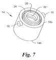
- the collar 14 has the general shape of a hollow cylinder terminating at the distal end with an annulus 20 having a central bore 22 sized to receive and retain the distal end 2a of the barrel 2 or the hub 5 if the distal end 2a of the barrel 2 is configured as a hub.
- the annulus 20 is sufficiently compliant and sized to allow passage of the hub 5 through the bore 22 and then to rotatably engage the hub 5.
- the outer surface of the annulus 20 has a generally circular channel 24 to receive one end of the force member (e.g., a coil spring) 16.
- a circumferential step 26 see, Fig.
- the collar 14 may have a corresponding plurality of pins.
- the distal end 2a of the barrel 2 or the hub 5 may be inserted into and through the proximal end 14b of the collar 14 and into and through the distal end 14a of the collar 14.
- the bore 22 in the annulus 20 expands until the hub 5 passes completely therethrough.
- the annulus 20 then return to its initial state in which the distal end 14a of the collar 14 abuts the proximal surface 5b of the hub 5, thereby rotatably attaching the collar 14 on the barrel 2 between the hub 5 and a shoulder or enlarged portion of the distal end 2a of the barrel 2.
- the track S comprises three track segments.
- a first track segment S 1 is provided to allow the safety device 10 to be assembled and inspected after the collar 14 has been attachment to the distal end 2a of the barrel 2 as discussed above.
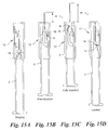
- the first track segment S 1 extends from a staging position (i) shown in Fig. 15A having a first catch 32 to a pre-injection position (ii) shown in Fig. 15B having a second catch 34 and has as a profile an initial portion (a) substantially parallel to the longitudinal axis A of the outer tube 12 followed by a final portion (b) angled with respect to the longitudinal axis A and serving as a cammed surface.
- the proximal end 12b of the outer tube 12 is in register with the distal end 2a of the barrel 2 allowing the barrel 2 to be inspected.
- the force element 16 is inserted in the outer tube 12.
- the collar 14, attached to the distal end 2a of the barrel 2 is then inserted in the outer tube 12 such that the pin 18 (or plurality of pins, if there is a plurality of tracks) is in the first track segment S 1 (or plurality of first track segments).
- the outer tube 12 is moved in the proximal direction causing an initial compression of the force element 16 as the pin 18 travels to the beginning of the first track segment S 1 and becomes releasably retained in the first catch 32 thereby securing the outer tube 12 in the staging position (i).
- the pin 18 travels the initial portion of the first track segment S 1 and is guided to the pre-injection position (ii) by the cammed surface which imparts an angular rotation to the collar releasably securing the pin 18 in second catch 34
- the cannula 3 extends a first length L 1 beyond the distal end of the outer tube 12.
- the length L1 of cannula extension depends on the particular size and configuration of the insertion device 1. At a minimum the length of extension allows visualization of the distal most tip of the cannula 3 at an insertion location prior to penetration of the skin.
- a second track segment S 2 contiguous with the first track segment S 1 extends from the pre-injection position (ii) to a full-insertion position (iii) shown in Fig. 15C ..
- the second track segment S 2 is angled with respect to the longitudinal axis of the outer tube 12 and has an arcuate profile (c).
- the distal end 12a of the outer tube 12 makes contact with the skin.
- the force applied by the skin to the outer tube 12 moves the pin 18 out of the first catch 32 and along beginning of the second track segment S 2 .
- continued application of force by the skin to the outer tube 12 further moves the outer tube 12 in the proximal direction and the pin 18 in the distal direction along the second track segment S 2 to the fully inserted position (iii).
- the cannula 3 extends a second length L 2 greater than the first length L 1 from the distal end 12a of the outer tube 12.
- the length L2 of cannula extension at the full-insertion position (iii) depends on the particular size and configuration of the insertion device 1 and the subcutaneous location the medicament is to be delivered.
- the second track segment guides the pin 18 along a generally arcuate path imparting both axial translation and rotation to the collar 14.
- the outer tube 12 remains in the full-insertion position (iii) until withdrawal of the cannula 3 is initiated, typically after a full dose of the medicament is delivered.
- a third track segment S 3 contiguous with the second track segment S 2 extends from the full-insertion position (iii) to a locked position (iv) shown in Fig. 15D having a third catch 36 in which the pin 18 is immovably retainable.
- the third track segment S 3 has an initial portion (d) extending from the full-insertion position (iii) substantially parallel to the longitudinal axis of the outer tube followed by an arcuate profile (e) providing a cammed surface terminating in an axially extending locked position (iv).
- the force applied by the skin to the outer tube 12 decreases and the outer tube 12 moves in the distal direction relative to the collar 14 under the reactive force of the force member 16 compressed between the collar and the outer tube.
- the third track segment S 3 initially guides the pin 18 substantially parallel to the longitudinal axis and then along a generally arcuate path imparting both axial translation and a rotation to the collar and finally into the locked position (iv).
- Figs. 8-14 another preferred embodiment of a low radial profile needle safety device, generally designated 100, and hereinafter referred to as the "safety device” 100 in accordance with the present invention.
- the safety device 100 is also for use with the injection device 1 disclosed above.
- the safety device 100 comprises an outer tube 112 configured to slidably receive therein a portion of the distal end 2a of the barrel 2.
- At least one track S' is formed in the inner surface of the outer tube 112.
- the at least one track S' has a plurality of contiguous segments further discussed below.
- the inner surface may have a plurality of tracks, each having the same configuration, positioned in a spaced-apart, aligned arrangement.
- a portion of the outer tube 112 has a generally U-shaped cut therethrough forming a flexible tongue 138 having a radially disposed ramp 140.
- a collar 114 is slidably received in the outer tube 112.
- the collar 114 is attachable to the distal end 2a of the barrel 2.
- At least one pin 118 extends radially outwardly from a sidewall of the collar 114 and is slidably received in the at least one track S' formed in the inner surface of the outer tube 112.
- the collar 114 may have a corresponding plurality of pins 118 projecting radially outwardly from spaced-apart locations around the circumference of the sidewall.
- a force member 116 extending between the outer tube 112 and the collar 114 biases the outer tube 112 in a distal direction.
- opposed ends of the force member 116 may be received and retained in a circumferential channel 124 in the outer surface of the collar 114 and a circumferential step 126 in the inner surface of the distal end 112a of the outer tube 112.
- the collar 114 is a body of revolution having a bore 122 therethrough and includes at least one and preferably four spaced-apart fingers 128 fixedly attachable to the distal end 2a of the barrel 2.
- Each finger 128 is sufficiently compliant to allow passage of the hub 5 through the bore 122 of the collar 114 and then to return to an initial configuration.
- Each finger 128 preferable is configured to conform to the size and/or shape of a corresponding portion of the distal end 2a of the barrel 2.
- a gap or spacing 130 is preferably located between adjacent fingers 128, which allows for the collective expansion and contraction of the four fingers 128.
- a channel formed in the distal end 128a of each finger 128 collectively forms a circular channel 124 in the outer surface of the collar 114 to receive one end of the force element 116.
- a circumferential step 126 ( see, Figs. 12 and 13 ) in the inner surface of the outer tube 112 is sized to receive and engage the distal end of the force member 116.
- Diametrically opposed pins 118 extends radially outwardly from the collar 114 and are sized to slidingly engage the at least one track S' formed in the inner surface of the outer tube 112.
- the hub 5 may be inserted into and through the proximal end 114b of the collar 114 and into and through the distal end 114a of the collar 114.
- each of the fingers 128 may flex radially outwardly from the longitudinal axis A until the hub 5 passes completely therethrough.
- the fingers 128 then return to their initial state in which the distal end 128a of each finger 128 abuts the proximal surface 5b of the hub 5, thereby immovably attaching the collar 114 in place on the barrel 2 between the hub 5 and a shoulder or enlarged portion of the distal end 2a of the barrel 2.
- the hub 5 may have a portion below the proximal surface 5b having ribs that extend into the gaps 130 between the fingers 128 further preventing rotation of the collar 114.
- the track S' has a plurality of segments, each segment corresponding to a relative position of the outer tube 112 with respect to the distal end 2a of the barrel 2 and/or to the cannula 3 projecting from the hub 5.
- a first track segment S 1 ' is provided to allow the safety device 100 to be assembled and inspected after the collar 114 has been attachment to the distal end 2a of the barrel 2 as discussed above.
- the first track segment S 1 ' extends from a staging position (i) having a catch 132 to a pre-injection position (ii) having a catch 134 and has as a profile an initial portion a' substantially parallel to the longitudinal axis of the outer tube followed by a circumferential portion b' terminating in the catch 134 in register with the radially disposed ramp 140 on the flexible tongue 138 of the outer tube 112.
- the proximal end 112b of the outer tube 112 is in register with the distal end 2a of the barrel 2 allowing the barrel 2 to be inspected.
- the force member 116 is inserted in the outer tube 112.
- the collar 118 attached to the distal end 2a of the barrel 2, is then inserted in the outer tube 112 such that the pins 118 are in the catch 132 at the staging position (i).
- the outer tube 112 is moved in the proximal direction causing the force member 116 to be compressed as the pins 118 travel the length of the initial portion a' of the first track segment S 1 '.
- the outer tube 112 is then rotated to move the pins 118 along the circumferential portion b' until the pins 118 become releasably retained in the catch 134 thereby securing the outer tube 112 in the pre-injection position (ii).
- the collar 114 is attached to the distal end 2a of the barrel 2 and the pin 118 is in the second catch 134, the cannula 3 extends a first length L 1 beyond the distal end of the outer tube 112.
- a second track segment S 2 ' contiguous with the first track section S 1 ', extends substantially parallel to the longitudinal axis A of the outer tube 112 from the pre-injection position (ii) to the full-insertion position (iii) of the outer tube.
- the distal end 112a of the outer tube 112 makes contact with the skin.
- the force applied by the skin to the outer tube 112 causes the flexible tongue 138 to deflect radially outwardly as the pin 118 moves out of the catch 132, up the radially disposed ramp 140 and along the second track segment S 2 '.
- the cannula 3 extends a second length L 2 greater than the first length L 1 from the distal end 112a of the outer tube 112.
- the second track segment guides the pin 18 along a path substantially parallel to the longitudinal axis of the outer tube 112.
- the outer tube 112 remains in the full-insertion position (iii) until withdrawal of the cannula 3 is initiated, typically after a full dose of the medicament is delivered.
- a third track segment S 3 ' contiguous with the second track segment S 2 ', has a profile having an initial portion c' extending from the fully inserted position (iii) substantially parallel to the longitudinal axis A of the outer tube 112 to a mid portion d' having a first extent d 1 ' angled with respect to the longitudinal axis A followed by a second extent d 2 ' parallel to the longitudinal axis A.
- the mid portion d' is followed by a final portion e' having an arcuate profile providing a cammed surface terminating in an axially extending locked position (iv).
- the force applied by the skin to the outer tube 112 decreases.
- the outer tube 112 moves in the distal direction.
- the pins 118 move in the proximal direction along the third track segment S 3 ' which guides the pins 118 in the initial portion c' substantially parallel to the longitudinal axis A imparting to the outer tube 112 translation in the axial direction without rotation.
- the first extent d 1 ' of the mid portion d' cams the pins 118 in a direction angled with respect to the longitudinal axis A imparting to the outer tube 112 translation in the axial direction with rotation.
- the second extent d 2 ' of the mid portion d' guides the pins 118 substantially parallel to the longitudinal axis A imparting to the outer tube 112 translation in the axial direction without rotation.
- the final portion e' of the third track segment S 3 ' guides the pins 118 in a generally arcuate path imparting to the outer tube 112 both axial translation and a rotation until the pins 118 are in the locked position (iv) in the catch 136. In the locked position, the outer tube 112 is fully extended covering the cannula 3 in the entirety and is prevented from moving in the distal or proximal directions.
Landscapes
- Health & Medical Sciences (AREA)
- Engineering & Computer Science (AREA)
- Heart & Thoracic Surgery (AREA)
- Vascular Medicine (AREA)
- Anesthesiology (AREA)
- Biomedical Technology (AREA)
- Environmental & Geological Engineering (AREA)
- Hematology (AREA)
- Life Sciences & Earth Sciences (AREA)
- Animal Behavior & Ethology (AREA)
- General Health & Medical Sciences (AREA)
- Public Health (AREA)
- Veterinary Medicine (AREA)
- Infusion, Injection, And Reservoir Apparatuses (AREA)
Claims (12)
- Nadelschutzanordnung (10, 100) für eine Injektionsvorrichtung (1) mit einem allgemeinen Zylinder (2), der ein distales Ende hat, von welchem sich eine Kanüle (3) erstreckt, wobei die Nadelschutzanordnung (10) umfasst:ein Außenrohr (12, 112), in welchem der Zylinder (2) gleitbeweglich aufgenommen ist, wobei das Außenrohr (12, 112) ein distales Ende und ein proximales Ende hat;eine Manschette (14, 114), die in dem Außenrohr (12, 112) positioniert ist, relativ zu diesem bewegbar ist und an dem distalen Ende des Zylinders (2) anbringbar ist;ein Kraftelement (16, 116), das in dem Außenrohr (12, 112) positioniert ist und das Außenrohr (12, 112) in eine distale Richtung vorspannt;eine Führungsbahn (S, S'), die an einer Innenfläche des Außenrohres (12, 112) gebildet ist; undeinen Zapfen (18, 118), der sich von der Manschette (14, 114) radial nach außen erstreckt und sich mit der Führungsbahn (S, S') gleitbeweglich im Eingriff befindet,dadurch gekennzeichnet, dass die Führungsbahn umfasst:ein erstes Führungsbahnsegment (S1, S1'), das sich von einer Stützposition (i) zu einer Vorinjektionsposition (ii) erstreckt,wobei das proximale Ende des Außenrohres (12, 122) mit dem distalen Ende des Zylinders (2) übereinstimmt, so dass der Zylinder (2) inspiziert werden kann, wenn die Manschette (14, 114) an dem distalen Ende des Zylinders angebracht ist und der Zapfen (18, 118) durch ein erste Rastung (32, 132) in dem Außenrohr (1, 112) lösbar in der Stützposition gehalten wird, undwobei sich die Kanüle (3) mit einer ersten Länge (L1) über das distale Ende des Außenrohres (12, 112) hinaus erstreckt, wenn die Manschette (14, 114) an dem distalen Ende des Zylinders (2) angebracht ist und der Zapfen (18, 118) durch eine zweite Rastung (34, 134) in dem Außenrohr (12, 112) in der Vorinjektionsposition (ii) gehalten wird;ein zweites Führungsbahnsegment (S2, S2'), das sich an das erste Führungsbahnsegment (S1, S1') anschließt und sich von der Vorinjektionsposition (ii) in eine Volleinschubposition (iii) erstreckt,wobei die Kanüle (3) sich mit einer zweiten Länge (L2), die größer als die erste Länge (L1) ist, von dem distalen Ende des Außenrohres (12, 112) erstreckt, wenn die Manschette (14, 114) an dem distalen Ende des Zylinders (2) angebracht ist und der Zapfen (18, 118) sich in der Volleinschubposition (iii) befindet; undein drittes Führungsbahnsegment (S3, S3'), das sich an das zweite Führungsbahnsegment (S2, S2') anschließt und sich von der Volleinschubposition (iii) in eine Sperrposition (iv) bewegt, in welcher der Zapfen (18, 118) unbeweglich gehalten wird,wobei sich die Kanüle (3) vollständig innerhalb des Außenrohres (12, 112) befindet, wenn die Manschette (14, 114) an dem distalen Ende des Zylinders (2) angebracht ist und der Zapfen (18, 118) sich in der Sperrposition (iv) in einer dritten Rastung (36, 136) in dem Außenrohr befindet.
- Nadelschutzanordnung (10) nach Anspruch 1, wobei die Manschette (14) ein Hohlzylinder ist, der an einem distalen Ende endet, wobei ein Ring (20) an dem distalen Ende des Zylinders (2) drehbar befestigt werden kann.
- Nadelschutzanordnung (10) nach Anspruch 1, wobei das erste Führungsbahnsegment (S1) einen zur Längsachse (A) des Außenrohres (12) im Wesentlichen parallelen Anfangsbereich hat, auf den ein Endbereich folgt, der bezüglich der Längsachse (A) abgewinkelt ist.
- Nadelschutzanordnung (10) nach Anspruch 1, wobei das zweite Führungsbahnsegment (S2) bezüglich der Längsachse (A) des Außenrohres (12) abgewinkelt ist, ein bogenförmiges Profil hat und der Manschette (14, 114) sowohl eine axiale Translation als auch eine Rotation aufprägt.
- Nadelschutzanordnung (10) nach Anspruch 1, wobei das dritte Führungsschienensegment (S3) einen zur Längsachse (A) des Außenrohres (12) im Wesentlichen parallelen Anfangsabschnitt hat, auf den ein bogenförmiger Abschnitt folgt, der eine mit einem Nocken versehene Fläche bereitstellt, die in der arretierten Position (iv) in einer sich axial erstreckenden Rastung (36) endet.
- Nadelschutzanordnung (10, 110) nach Anspruch 1, wobei die Manschette (114) ein Hohlzylinder ist, der an einem distalen Ende mit einer Mehrzahl von voneinander beabstandeten Fingern (128) endet, die an dem distalen Ende des Zylinders (2) fest angebracht werden können.
- Nadelschutzanordnung (100) nach Anspruch 1, wobei das Außenrohr (112) einen durchgehenden Einschnitt hat, der eine flexible Zunge (138) bildet, die eine radial angeordnete Schrage (140) ha.
- Nadelschutzanordnung (100) nach Anspruch 1, wobei das Außenrohr (112) einen durchgehenden Einschnitt hat, der eine flexible Zunge (138) bildet, die eine radial angeordnete Schräge (140) hat, die mit der zweiten Rastung (134) übereinstimmt, und wobei das erste Führungsbahnsegment (S1') einen zur Längsachse (A) des Außenrohres (112) im Wesentlichen parallelen Anfangsabschnitt hat, auf den ein an der zweiten Rastung (134) endender Umfangsabschnitt folgt.
- Nadelschutzanordnung (100) nach Anspruch 1, wobei das zweite Führungsbahnsegment (S2') zur Längsachse (A) des Außenrohres (112) im Wesentlichen parallel ist.
- Nadelschutzanordnung (100) nach Anspruch 1, wobei das dritte Führungsbahnsegment (S3') einen zur Längsachse (A) des Außenrohres (112) im Wesentlichen parallelen Anfangsabschnitt hat, auf welchen ein Mittelabschnitt mit einer bezüglich der Längsachse (A) abgewinkelten ersten Erstreckung und einer zur Längsachse (A) parallelen zweiten Erstreckung folgt, auf welchen ein Endabschnitt folgt, der ein bogenförmiges Profil hat, das eine mit einem Nocken versehene Fläche bereitstellt, die in einer arretierten Position (iv) in einer sich axial erstreckenden dritten Rastung (136) endet.
- Nadelschutzanordnung (10, 100) nach Anspruch 1, wobei das Außenrohr (12, 112) sich nur in axialer Translation ohne Rotation bewegt, wenn sich die Kanüle (3) über das Außenrohr (12, 112) hinaus erstreckt.
- Nadelschutzanordnung (10, 100) nach Anspruch 1, wobei das Kraftelement (16, 116) innerhalb des Außenrohres (12,112) zwischen der Manschette (14, 114) und dem distalen Ende des Außenrohres (12, 112) positioniert ist.
Applications Claiming Priority (2)
| Application Number | Priority Date | Filing Date | Title |
|---|---|---|---|
| US201261607711P | 2012-03-07 | 2012-03-07 | |
| PCT/US2013/029518 WO2013134465A1 (en) | 2012-03-07 | 2013-03-07 | Low radial profile needle safety device |
Publications (2)
| Publication Number | Publication Date |
|---|---|
| EP2822621A1 EP2822621A1 (de) | 2015-01-14 |
| EP2822621B1 true EP2822621B1 (de) | 2016-09-21 |
Family
ID=48087683
Family Applications (1)
| Application Number | Title | Priority Date | Filing Date |
|---|---|---|---|
| EP13715786.3A Active EP2822621B1 (de) | 2012-03-07 | 2013-03-07 | Nadelschutzanordnung mit geringem radialen profil |
Country Status (3)
| Country | Link |
|---|---|
| US (2) | US9907916B2 (de) |
| EP (1) | EP2822621B1 (de) |
| WO (1) | WO2013134465A1 (de) |
Families Citing this family (27)
| Publication number | Priority date | Publication date | Assignee | Title |
|---|---|---|---|---|
| WO2013134465A1 (en) * | 2012-03-07 | 2013-09-12 | West Pharmaceutical Services, Inc. | Low radial profile needle safety device |
| US10004854B2 (en) | 2012-03-07 | 2018-06-26 | West Pharmaceutical Services, Inc. | Low radial profile needle safety device |
| US20140257200A1 (en) * | 2013-03-11 | 2014-09-11 | Judith Auerbach | Safety system for a needle retaining device |
| CN107261263B (zh) * | 2013-08-14 | 2020-04-28 | 泰尔茂株式会社 | 注射器 |
| EP3107603B1 (de) * | 2014-02-18 | 2018-03-28 | Skufca, Peter | Ausgabesystem zur ausgabe von medizinischen oder pharmazeutischen verbindungen |
| CN106102807A (zh) * | 2014-03-11 | 2016-11-09 | 尼普洛株式会社 | 针组件 |
| CN104307072A (zh) * | 2014-10-29 | 2015-01-28 | 杭州普昂医疗科技有限公司 | 安全式胰岛素笔针 |
| FR3031904B1 (fr) * | 2015-01-26 | 2021-08-27 | Biocorp Rech Et Developpement | Dispositif de protection d'une aiguille, seringue equipee d'un tel dispositif et procede de fabrication de seringues pre-remplies a aiguille collee |
| JP6746591B2 (ja) * | 2015-01-26 | 2020-08-26 | バイオコープ・プロダクション | 針を保護するためのデバイス、かかるデバイスを備えるシリンジ、および事前充填されたセメント固定針シリンジを作製するための方法 |
| EP3251715B1 (de) | 2015-01-30 | 2020-01-29 | Terumo Kabushiki Kaisha | Schutz und medizinische instrumentenanordnung |
| WO2016158627A1 (ja) * | 2015-03-30 | 2016-10-06 | テルモ株式会社 | 穿刺針保護用組立体、注射器組立体及びその製造方法 |
| DK3106194T3 (da) * | 2015-06-15 | 2019-05-20 | Gerresheimer Regensburg Gmbh | Sikkerhedsanordning til en sprøjte |
| EP3106191B1 (de) | 2015-06-15 | 2019-03-13 | Gerresheimer Regensburg GmbH | Sicherheitsvorrichtung für eine spritze |
| FR3037807B1 (fr) * | 2015-06-23 | 2017-08-11 | Biocorp Prod | Seringue a aiguille collee |
| DE102015110343A1 (de) | 2015-06-26 | 2016-12-29 | Gerresheimer Regensburg Gmbh | Mehrteilige Sicherheitsvorrichtung für eine Spritze |
| DE102015111840B4 (de) * | 2015-07-21 | 2019-08-01 | Gerresheimer Bünde Gmbh | Sicherheitsvorrichtung für eine Spritze |
| DE102015111835A1 (de) | 2015-07-21 | 2017-01-26 | Gerresheimer Regensburg Gmbh | Sicherheitsvorrichtung für eine Spritze |
| EP3434304B1 (de) * | 2016-03-25 | 2021-11-24 | Terumo Kabushiki Kaisha | Schutzvorrichtung und medizinische instrumentenanordnung |
| FR3063909B1 (fr) | 2017-03-17 | 2022-03-11 | Biocorp Prod | Dispositif de protection d'aiguille pour une seringue pre-remplie a aiguille collee et seringue comprenant un tel dispositif |
| EP3597244A4 (de) | 2017-03-17 | 2020-09-02 | Terumo Kabushiki Kaisha | Spritzenanordnung |
| FR3074424B1 (fr) * | 2017-12-06 | 2021-11-05 | Biocorp Prod | Systeme de securite apres usage pour une seringue a aiguille collee et seringue equipee d'un tel systeme |
| USD851246S1 (en) | 2018-01-19 | 2019-06-11 | West Pharmaceutical Services, Inc. | Multi-part collar |
| CN108543169B (zh) * | 2018-05-16 | 2023-12-01 | 普昂(杭州)医疗科技股份有限公司 | 一种安全式胰岛素笔针 |
| US11224701B1 (en) | 2019-08-21 | 2022-01-18 | Jarvis Patton | Single dose disposable syringe with needle protector |
| CN113304359B (zh) * | 2020-02-27 | 2024-03-15 | 易迪思工业设计顾问(上海)有限公司 | 一种用于注射器的保护装置 |
| US12005244B2 (en) | 2020-03-27 | 2024-06-11 | Medivena Sp. Z O.O. | Needle-based device based on direct wing-based coupling of a needle shield to a barrel thereof and safety mechanism implemented therein |
| CN112618875A (zh) * | 2021-02-09 | 2021-04-09 | 上海倍莱弗科技有限公司 | 一种注射器用安全定位装置 |
Family Cites Families (104)
| Publication number | Priority date | Publication date | Assignee | Title |
|---|---|---|---|---|
| US4425120A (en) * | 1982-04-15 | 1984-01-10 | Sampson Norma A | Shielded hypodermic syringe |
| US4731059A (en) * | 1986-10-14 | 1988-03-15 | Medical Safety Products, Inc. | Combination needle shield/needle guard device positively locked onto detachable needle assemblies for an evacuated blood collection system and a hypodermic syringe |
| US5569190A (en) | 1987-06-08 | 1996-10-29 | D'antonio; Nicholas F. | Hypodermic fluid dispenser |
| GB8713810D0 (en) | 1987-06-12 | 1987-07-15 | Hypoguard Uk Ltd | Measured dose dispensing device |
| US4923446A (en) * | 1988-04-14 | 1990-05-08 | Page Mary J | Shield for devices capable of penetrating skin |
| US4917673A (en) * | 1988-10-31 | 1990-04-17 | Coplin Allan J | Assembly for the protection against inadvertent puncture by medical needles |
| US4900311A (en) * | 1988-12-06 | 1990-02-13 | Lawrence Stern | Hypodermic syringe |
| US4894055A (en) | 1988-12-28 | 1990-01-16 | Sudnak Paul J | Needle guard assembly for use with hypodermic syringes and the like |
| US6017329A (en) | 1989-03-02 | 2000-01-25 | Hake; Lawrence W. | Hypodermic needle guard and method to prevent needle stick injuries |
| US4966592A (en) | 1989-05-05 | 1990-10-30 | Burns Cameron A | Protective sleeve for hypodermic needle |
| US5312347A (en) | 1992-02-27 | 1994-05-17 | Osborne Barbara J | Hypodermic needle shield |
| GB9212742D0 (en) * | 1992-06-16 | 1992-07-29 | Sterimatic Holdings Ltd | Syringe or blood collection system |
| US5267972A (en) | 1992-07-20 | 1993-12-07 | Anderson Wayne W | Hypodermic syringe with needle guard |
| US5242401A (en) | 1992-10-09 | 1993-09-07 | Colsky Andrew E | Disposable needle head assembly |
| US5346480A (en) * | 1992-12-14 | 1994-09-13 | Q-Med, Inc. | Syringe with retractable needle |
| US5389085A (en) | 1993-02-11 | 1995-02-14 | International Medical Consultants, Inc. | Automatic needle protector |
| US5472430A (en) | 1993-08-18 | 1995-12-05 | Vlv Associates | Protected needle assembly |
| DE4434644C2 (de) | 1994-09-28 | 1997-08-07 | Schott Glaswerke | Behältnis zur Lagerung und Verabreichung von Injektions-, Infusions- und Diagnostikpräparaten |
| US5624402A (en) | 1994-12-12 | 1997-04-29 | Becton, Dickinson And Company | Syringe tip cap |
| US6196998B1 (en) | 1994-12-12 | 2001-03-06 | Becton Dickinson And Company | Syringe and tip cap assembly |
| US5595566A (en) * | 1995-01-31 | 1997-01-21 | Unique Management Enterprises, Inc. | Apparatus for shielding a syringe needle |
| FR2736553B1 (fr) | 1995-07-12 | 1998-01-09 | Soc Et Et D Applic Tech Sedat | Seringue d'injection, notamment de produits medicaux liquides, a protecteur d'aiguille mobile |
| US5591138A (en) * | 1995-08-10 | 1997-01-07 | Vaillancourt; Vincent L. | Protected needle assembly |
| DE19537163C1 (de) | 1995-10-06 | 1997-01-30 | Vetter & Co Apotheker | Spritze für medizinische Zwecke |
| US5688241A (en) * | 1996-04-15 | 1997-11-18 | Asbaghi; Hooman Ali | Automatic non-reusable needle guard |
| JP3380705B2 (ja) | 1997-03-12 | 2003-02-24 | 株式会社大協精工 | 注射器兼容器用密封ゴム栓 |
| DE19755125B4 (de) | 1997-12-11 | 2006-04-20 | Tecpharma Licensing Ag | Nadelschutzvorrichtung für Injektionsgeräte |
| USD447797S1 (en) | 1998-10-13 | 2001-09-11 | Becton, Dickinson And Company | Syringe |
| USD430293S (en) | 1998-11-24 | 2000-08-29 | Becton Dickinson And Company | Tamper evident cap for a tip cap |
| USD431864S (en) | 1998-11-24 | 2000-10-10 | Becton Dickinson And Company | Tamper evident cap for a tip cap |
| DE19909824A1 (de) | 1999-03-05 | 2000-09-07 | Vetter & Co Apotheker | Spritze für medizinische Zwecke und Verfahren zu ihrer Montage |
| US20010031949A1 (en) * | 1999-06-18 | 2001-10-18 | Asbaghi Hooman A. | Protective device for a prefilled injection syringe |
| US20020004652A1 (en) * | 1999-06-18 | 2002-01-10 | Asbaghi Hooman A. | Protective device for a fillable injection syringe |
| US6491667B1 (en) | 1999-08-31 | 2002-12-10 | Becton, Dickinson And Company | Syringe tip cap |
| DE10009814B4 (de) | 2000-03-01 | 2008-03-06 | Tecpharma Licensing Ag | Einweg-Injektorkappe |
| GB0007071D0 (en) | 2000-03-24 | 2000-05-17 | Sams Bernard | One-way clutch mechanisms and injector devices |
| US6632199B1 (en) | 2000-05-23 | 2003-10-14 | Becton Dickinson And Company | Syringe assembly including plastic tip cap |
| US6547764B2 (en) | 2000-05-31 | 2003-04-15 | Novo Nordisk A/S | Double pointed injection needle |
| US6432088B1 (en) | 2000-06-06 | 2002-08-13 | Wu-Shun Huang | Safety syringe with a needle sleeve lock |
| US6663602B2 (en) | 2000-06-16 | 2003-12-16 | Novo Nordisk A/S | Injection device |
| US6986760B2 (en) | 2000-08-02 | 2006-01-17 | Becton, Dickinson And Company | Pen needle and safety shield system |
| WO2002009797A1 (en) | 2000-08-02 | 2002-02-07 | Becton Dickinson And Company | Pen needle and safety shield system |
| DE10127779A1 (de) | 2001-06-01 | 2002-12-12 | Vetter & Co Apotheker | Verschlusselement |
| USD457954S1 (en) | 2001-06-19 | 2002-05-28 | Becton, Dickinson And Company | Syringe tip cap |
| USD461244S1 (en) | 2001-08-21 | 2002-08-06 | Becton, Dickinson And Company | Needle holder |
| PL196617B1 (pl) | 2001-11-30 | 2008-01-31 | Novo Nordisk As | Zespół bezpiecznej igły |
| USD468016S1 (en) | 2001-11-30 | 2002-12-31 | Alaris Medical Systems, Inc. | Medical fluid connector |
| US6648858B2 (en) | 2001-12-21 | 2003-11-18 | Visual Connections, Inc. | Safety device for a sheathed, prefilled injection syringe |
| US20030144630A1 (en) * | 2002-01-28 | 2003-07-31 | Chang Yu Kang | Safety syringe |
| US6821267B2 (en) | 2002-03-07 | 2004-11-23 | Baxter International | Luer tip cap having reduced removal force |
| US6776777B2 (en) | 2002-05-10 | 2004-08-17 | Becton, Dickinson And Company | Passive safety shield system for injection devices |
| GB0214452D0 (en) | 2002-06-22 | 2002-07-31 | Liversidge Barry P | Medical needle assemblies |
| DE10247965A1 (de) | 2002-10-15 | 2004-05-06 | Transcoject Gesellschaft für medizinische Geräte mbH & Co KG | Originalitätsverschluss für eine Spritze |
| US6884237B2 (en) * | 2002-12-10 | 2005-04-26 | Inviro Medical Devices, Inc. | Position guide for a needle guard |
| USD493526S1 (en) | 2003-04-22 | 2004-07-27 | Becton, Dickinson And Company | Syringe tip cap |
| US6926697B2 (en) | 2003-05-13 | 2005-08-09 | Robert Malenchek | Adaptor for converting a non-safety syringe into a safety syringe |
| IL157984A (en) | 2003-09-17 | 2015-02-26 | Dali Medical Devices Ltd | Automatic needle |
| US20050075611A1 (en) | 2003-10-01 | 2005-04-07 | Hetzler Kevin G. | Low extractable, thermoplastic syringe and tip cap |
| US7497847B2 (en) | 2003-11-03 | 2009-03-03 | Becton, Dickinson And Company | Safety shield system for a syringe |
| GB0327136D0 (en) | 2003-11-21 | 2003-12-24 | Nmt Group Plc | Safety needle |
| DE502005001350D1 (de) | 2004-05-29 | 2007-10-11 | Gerresheimer Buende Gmbh | Spritzenverschluss und Verfahren zum Herstellen eines Spritzenverschlusses |
| EP1814615B1 (de) * | 2004-11-24 | 2015-10-28 | SHL Group AB | Injektionsvorrichtung |
| US8062252B2 (en) * | 2005-02-18 | 2011-11-22 | Becton, Dickinson And Company | Safety shield system for a syringe |
| FR2884723B1 (fr) * | 2005-04-20 | 2008-03-14 | Becton Dickinson France Soc Pa | Dispositif de protection d'un dispositif d'injection |
| DE102005052545A1 (de) | 2005-11-02 | 2007-05-03 | Schering Ag | Verschluß für eine medizinische Spritze |
| US8062265B2 (en) | 2005-11-04 | 2011-11-22 | Don Millerd | Automatic needle guard for medication pen |
| GB0600212D0 (en) * | 2006-01-06 | 2006-02-15 | Liversidge Barry P | Medical needle safety device |
| DE102006053055A1 (de) | 2006-09-01 | 2008-04-17 | Tecpharma Licensing Ag | Nadelschutzvorrichtung mit blockierter Schutzposition |
| DE102006042233B3 (de) | 2006-09-06 | 2008-03-06 | Tecpharma Licensing Ag | Nadelschutzvorrichtung mit distalem und proximalem Nadelschutz |
| EP1923083A1 (de) | 2006-11-17 | 2008-05-21 | Sanofi-Aventis Deutschland GmbH | Antriebsmechanismen für Medikamentenabgabevorrichtungen |
| US7462168B2 (en) | 2007-01-23 | 2008-12-09 | Becton, Dickinson And Company | Safety pen needle with passive safety shield system |
| FR2913200B1 (fr) | 2007-03-02 | 2009-12-11 | Becton Dickinson France | Dispositif de protection d'aiguille |
| USD570478S1 (en) | 2007-05-29 | 2008-06-03 | Daikyo Seiko, Ltd. | Syringe nozzle cap |
| USD581049S1 (en) | 2007-06-25 | 2008-11-18 | Daikyo Seiko, Ltd. | Nozzle cap for syringe |
| USD589612S1 (en) | 2007-06-25 | 2009-03-31 | Daikyo Seiko, Ltd. | Nozzle cap for syringe |
| USD581046S1 (en) | 2007-06-25 | 2008-11-18 | Daikyo Seiko, Ltd. | Nozzle cap for syringe |
| WO2009040602A1 (en) * | 2007-09-25 | 2009-04-02 | Becton Dickinson France | Autoinject0r with deactivating means moveable by a safety shield |
| US8357125B2 (en) | 2007-09-25 | 2013-01-22 | Becton, Dickinson And Company | Autoinjector with deactivating means moveable by a safety shield |
| USD596290S1 (en) | 2007-12-25 | 2009-07-14 | Daikyo Seiko, Ltd. | Syringe barrel body cover |
| ES2732124T3 (es) | 2008-01-15 | 2019-11-20 | Becton Dickinson Co | Conjunto de aguja de pluma con mecanismo de inserción de aguja |
| DE102008013198B4 (de) | 2008-03-07 | 2011-07-14 | Bayer Schering Pharma Aktiengesellschaft, 13353 | Originalitätsverschluss mit Haltezapfen |
| FR2930162B1 (fr) | 2008-04-16 | 2011-05-13 | Becton Dickinson France | Ensemble de protection d'aiguille comportant un element de verrouillage. |
| CN102036705A (zh) | 2008-05-06 | 2011-04-27 | 海波赛非投资(控股)公司 | 皮下注射针头保护罩 |
| DK2424599T3 (da) * | 2009-04-27 | 2020-08-24 | Shl Medical Ag | Sikkerhedspenkanyleindretning |
| GB0913385D0 (en) | 2009-07-31 | 2009-09-16 | Medical House The Plc | Improved autoinjector |
| JP5660547B2 (ja) | 2009-08-19 | 2015-01-28 | セイフティー シリンジーズ インコーポレイテッド | 患者接触駆動の針刺し安全デバイス |
| EP2482901B1 (de) | 2009-09-30 | 2019-10-23 | Sanofi-Aventis Deutschland GmbH | Injektionsvorrichtung |
| CN102686255B (zh) | 2009-10-23 | 2014-11-26 | 邦奥鲁夫森梅迪康股份有限公司 | 具有自动针保护功能的自动注射器 |
| US8663174B2 (en) * | 2009-11-13 | 2014-03-04 | Becton, Dickinson And Company | Hub assembly having a hidden needle for a drug delivery pen |
| EP2515973B1 (de) | 2009-12-23 | 2018-02-21 | Tecpharma Licensing AG | Injektionsvorrichtung mit einer nadelschutzhülse |
| US9878100B2 (en) * | 2010-03-25 | 2018-01-30 | Sanofi-Aventis Deutschland Gmbh | Medicated module with automatic reservoir engagement |
| US20110319833A1 (en) * | 2010-06-24 | 2011-12-29 | Thomas Chun | Protective guard for needles of injection devices |
| US8303541B2 (en) * | 2010-06-24 | 2012-11-06 | Thomas Chun | Protective guard for needles of injection devices having removable needle assemblies |
| US9352099B2 (en) | 2010-07-02 | 2016-05-31 | Sanofi-Aventis Deutschland Gmbh | Safety device for a pre-filled syringe and injection device |
| CA2803195A1 (en) | 2010-07-02 | 2012-01-05 | Sanofi-Aventis Deutschland Gmbh | Safety device for a pre-filled syringe and injection device |
| RU2578360C2 (ru) * | 2010-07-02 | 2016-03-27 | Санофи-Авентис Дойчланд Гмбх | Инъекционное устройство |
| NZ604075A (en) | 2010-07-02 | 2014-03-28 | Sanofi Aventis Deutschland | Safety device for a pre-filled syringe and injection device |
| US8128594B1 (en) * | 2010-11-03 | 2012-03-06 | Chang li-feng | Safety syringe |
| EP2468333A1 (de) | 2010-12-21 | 2012-06-27 | Sanofi-Aventis Deutschland GmbH | Automatischer Injektor |
| US8986261B2 (en) | 2011-03-25 | 2015-03-24 | Sanofi-Aventis Deutschland Gmbh | Drug delivery device |
| US10004854B2 (en) * | 2012-03-07 | 2018-06-26 | West Pharmaceutical Services, Inc. | Low radial profile needle safety device |
| WO2013134465A1 (en) * | 2012-03-07 | 2013-09-12 | West Pharmaceutical Services, Inc. | Low radial profile needle safety device |
| JP5986464B2 (ja) | 2012-09-18 | 2016-09-06 | 住友理工株式会社 | トルクロッド |
| CN107261263B (zh) | 2013-08-14 | 2020-04-28 | 泰尔茂株式会社 | 注射器 |
-
2013
- 2013-03-07 WO PCT/US2013/029518 patent/WO2013134465A1/en active Application Filing
- 2013-03-07 US US14/383,364 patent/US9907916B2/en active Active
- 2013-03-07 EP EP13715786.3A patent/EP2822621B1/de active Active
-
2018
- 2018-02-20 US US15/900,234 patent/US10478568B2/en active Active
Also Published As
| Publication number | Publication date |
|---|---|
| US9907916B2 (en) | 2018-03-06 |
| US20180272077A1 (en) | 2018-09-27 |
| WO2013134465A1 (en) | 2013-09-12 |
| US20150018773A1 (en) | 2015-01-15 |
| US10478568B2 (en) | 2019-11-19 |
| EP2822621A1 (de) | 2015-01-14 |
Similar Documents
| Publication | Publication Date | Title |
|---|---|---|
| US10478568B2 (en) | Low radial profile needle safety device | |
| US11077259B2 (en) | Low radial profile needle safety device | |
| CN113797409B (zh) | 安全针装置 | |
| CN103079611B (zh) | 用于安全装置的针头护罩、安全装置和注射装置 | |
| RU2766673C2 (ru) | Захватное приспособление для ручного инъекционного устройства | |
| KR101792996B1 (ko) | 사전 충전된 주사기 및 주사 디바이스용 안전 디바이스 | |
| RU2766672C2 (ru) | Захватное приспособление для ручного инъекционного устройства | |
| CN103025371B (zh) | 用于预装填注射器的安全装置和注射装置 | |
| JP5017125B2 (ja) | 選択された針の構成を有する注射器ガード | |
| EP2857055B1 (de) | Ampullenadapter für doppelt abgeschirmte Spritze | |
| CN111201055B (zh) | 注射器针头安全系统及其组装方法 | |
| EP2763730B1 (de) | Nadelsicherheitsvorrichtung | |
| EP1946789A1 (de) | Sicherheitsschirmsystem für vorgefüllte Spritzen | |
| MX2014011004A (es) | Aguja de seguridad desmontable de funda retractil con resorte movil. | |
| CN113474024B (zh) | 在注射过程中自动且被动地保持针管安全的超低浪费针管和注射器系统 | |
| WO2012004804A1 (en) | Retractable syringe |
Legal Events
| Date | Code | Title | Description |
|---|---|---|---|
| PUAI | Public reference made under article 153(3) epc to a published international application that has entered the european phase |
Free format text: ORIGINAL CODE: 0009012 |
|
| 17P | Request for examination filed |
Effective date: 20140919 |
|
| AK | Designated contracting states |
Kind code of ref document: A1 Designated state(s): AL AT BE BG CH CY CZ DE DK EE ES FI FR GB GR HR HU IE IS IT LI LT LU LV MC MK MT NL NO PL PT RO RS SE SI SK SM TR |
|
| AX | Request for extension of the european patent |
Extension state: BA ME |
|
| DAX | Request for extension of the european patent (deleted) | ||
| GRAP | Despatch of communication of intention to grant a patent |
Free format text: ORIGINAL CODE: EPIDOSNIGR1 |
|
| INTG | Intention to grant announced |
Effective date: 20160406 |
|
| GRAS | Grant fee paid |
Free format text: ORIGINAL CODE: EPIDOSNIGR3 |
|
| GRAA | (expected) grant |
Free format text: ORIGINAL CODE: 0009210 |
|
| AK | Designated contracting states |
Kind code of ref document: B1 Designated state(s): AL AT BE BG CH CY CZ DE DK EE ES FI FR GB GR HR HU IE IS IT LI LT LU LV MC MK MT NL NO PL PT RO RS SE SI SK SM TR |
|
| REG | Reference to a national code |
Ref country code: GB Ref legal event code: FG4D |
|
| REG | Reference to a national code |
Ref country code: CH Ref legal event code: EP |
|
| REG | Reference to a national code |
Ref country code: AT Ref legal event code: REF Ref document number: 830543 Country of ref document: AT Kind code of ref document: T Effective date: 20161015 |
|
| REG | Reference to a national code |
Ref country code: IE Ref legal event code: FG4D |
|
| REG | Reference to a national code |
Ref country code: DE Ref legal event code: R096 Ref document number: 602013011822 Country of ref document: DE |
|
| REG | Reference to a national code |
Ref country code: LT Ref legal event code: MG4D Ref country code: NL Ref legal event code: MP Effective date: 20160921 |
|
| PG25 | Lapsed in a contracting state [announced via postgrant information from national office to epo] |
Ref country code: RS Free format text: LAPSE BECAUSE OF FAILURE TO SUBMIT A TRANSLATION OF THE DESCRIPTION OR TO PAY THE FEE WITHIN THE PRESCRIBED TIME-LIMIT Effective date: 20160921 Ref country code: FI Free format text: LAPSE BECAUSE OF FAILURE TO SUBMIT A TRANSLATION OF THE DESCRIPTION OR TO PAY THE FEE WITHIN THE PRESCRIBED TIME-LIMIT Effective date: 20160921 Ref country code: LT Free format text: LAPSE BECAUSE OF FAILURE TO SUBMIT A TRANSLATION OF THE DESCRIPTION OR TO PAY THE FEE WITHIN THE PRESCRIBED TIME-LIMIT Effective date: 20160921 Ref country code: NO Free format text: LAPSE BECAUSE OF FAILURE TO SUBMIT A TRANSLATION OF THE DESCRIPTION OR TO PAY THE FEE WITHIN THE PRESCRIBED TIME-LIMIT Effective date: 20161221 |
|
| REG | Reference to a national code |
Ref country code: AT Ref legal event code: MK05 Ref document number: 830543 Country of ref document: AT Kind code of ref document: T Effective date: 20160921 |
|
| PG25 | Lapsed in a contracting state [announced via postgrant information from national office to epo] |
Ref country code: GR Free format text: LAPSE BECAUSE OF FAILURE TO SUBMIT A TRANSLATION OF THE DESCRIPTION OR TO PAY THE FEE WITHIN THE PRESCRIBED TIME-LIMIT Effective date: 20161222 Ref country code: LV Free format text: LAPSE BECAUSE OF FAILURE TO SUBMIT A TRANSLATION OF THE DESCRIPTION OR TO PAY THE FEE WITHIN THE PRESCRIBED TIME-LIMIT Effective date: 20160921 Ref country code: NL Free format text: LAPSE BECAUSE OF FAILURE TO SUBMIT A TRANSLATION OF THE DESCRIPTION OR TO PAY THE FEE WITHIN THE PRESCRIBED TIME-LIMIT Effective date: 20160921 Ref country code: SE Free format text: LAPSE BECAUSE OF FAILURE TO SUBMIT A TRANSLATION OF THE DESCRIPTION OR TO PAY THE FEE WITHIN THE PRESCRIBED TIME-LIMIT Effective date: 20160921 |
|
| REG | Reference to a national code |
Ref country code: FR Ref legal event code: PLFP Year of fee payment: 5 |
|
| PG25 | Lapsed in a contracting state [announced via postgrant information from national office to epo] |
Ref country code: EE Free format text: LAPSE BECAUSE OF FAILURE TO SUBMIT A TRANSLATION OF THE DESCRIPTION OR TO PAY THE FEE WITHIN THE PRESCRIBED TIME-LIMIT Effective date: 20160921 Ref country code: RO Free format text: LAPSE BECAUSE OF FAILURE TO SUBMIT A TRANSLATION OF THE DESCRIPTION OR TO PAY THE FEE WITHIN THE PRESCRIBED TIME-LIMIT Effective date: 20160921 |
|
| PG25 | Lapsed in a contracting state [announced via postgrant information from national office to epo] |
Ref country code: SM Free format text: LAPSE BECAUSE OF FAILURE TO SUBMIT A TRANSLATION OF THE DESCRIPTION OR TO PAY THE FEE WITHIN THE PRESCRIBED TIME-LIMIT Effective date: 20160921 Ref country code: ES Free format text: LAPSE BECAUSE OF FAILURE TO SUBMIT A TRANSLATION OF THE DESCRIPTION OR TO PAY THE FEE WITHIN THE PRESCRIBED TIME-LIMIT Effective date: 20160921 Ref country code: CZ Free format text: LAPSE BECAUSE OF FAILURE TO SUBMIT A TRANSLATION OF THE DESCRIPTION OR TO PAY THE FEE WITHIN THE PRESCRIBED TIME-LIMIT Effective date: 20160921 Ref country code: IS Free format text: LAPSE BECAUSE OF FAILURE TO SUBMIT A TRANSLATION OF THE DESCRIPTION OR TO PAY THE FEE WITHIN THE PRESCRIBED TIME-LIMIT Effective date: 20170121 Ref country code: AT Free format text: LAPSE BECAUSE OF FAILURE TO SUBMIT A TRANSLATION OF THE DESCRIPTION OR TO PAY THE FEE WITHIN THE PRESCRIBED TIME-LIMIT Effective date: 20160921 Ref country code: PL Free format text: LAPSE BECAUSE OF FAILURE TO SUBMIT A TRANSLATION OF THE DESCRIPTION OR TO PAY THE FEE WITHIN THE PRESCRIBED TIME-LIMIT Effective date: 20160921 Ref country code: BE Free format text: LAPSE BECAUSE OF FAILURE TO SUBMIT A TRANSLATION OF THE DESCRIPTION OR TO PAY THE FEE WITHIN THE PRESCRIBED TIME-LIMIT Effective date: 20160921 Ref country code: BG Free format text: LAPSE BECAUSE OF FAILURE TO SUBMIT A TRANSLATION OF THE DESCRIPTION OR TO PAY THE FEE WITHIN THE PRESCRIBED TIME-LIMIT Effective date: 20161221 Ref country code: SK Free format text: LAPSE BECAUSE OF FAILURE TO SUBMIT A TRANSLATION OF THE DESCRIPTION OR TO PAY THE FEE WITHIN THE PRESCRIBED TIME-LIMIT Effective date: 20160921 Ref country code: PT Free format text: LAPSE BECAUSE OF FAILURE TO SUBMIT A TRANSLATION OF THE DESCRIPTION OR TO PAY THE FEE WITHIN THE PRESCRIBED TIME-LIMIT Effective date: 20170123 |
|
| REG | Reference to a national code |
Ref country code: DE Ref legal event code: R097 Ref document number: 602013011822 Country of ref document: DE |
|
| PG25 | Lapsed in a contracting state [announced via postgrant information from national office to epo] |
Ref country code: IT Free format text: LAPSE BECAUSE OF FAILURE TO SUBMIT A TRANSLATION OF THE DESCRIPTION OR TO PAY THE FEE WITHIN THE PRESCRIBED TIME-LIMIT Effective date: 20160921 |
|
| PLBE | No opposition filed within time limit |
Free format text: ORIGINAL CODE: 0009261 |
|
| STAA | Information on the status of an ep patent application or granted ep patent |
Free format text: STATUS: NO OPPOSITION FILED WITHIN TIME LIMIT |
|
| PG25 | Lapsed in a contracting state [announced via postgrant information from national office to epo] |
Ref country code: DK Free format text: LAPSE BECAUSE OF FAILURE TO SUBMIT A TRANSLATION OF THE DESCRIPTION OR TO PAY THE FEE WITHIN THE PRESCRIBED TIME-LIMIT Effective date: 20160921 |
|
| 26N | No opposition filed |
Effective date: 20170622 |
|
| REG | Reference to a national code |
Ref country code: CH Ref legal event code: PL |
|
| PG25 | Lapsed in a contracting state [announced via postgrant information from national office to epo] |
Ref country code: MC Free format text: LAPSE BECAUSE OF FAILURE TO SUBMIT A TRANSLATION OF THE DESCRIPTION OR TO PAY THE FEE WITHIN THE PRESCRIBED TIME-LIMIT Effective date: 20160921 Ref country code: SI Free format text: LAPSE BECAUSE OF FAILURE TO SUBMIT A TRANSLATION OF THE DESCRIPTION OR TO PAY THE FEE WITHIN THE PRESCRIBED TIME-LIMIT Effective date: 20160921 |
|
| PG25 | Lapsed in a contracting state [announced via postgrant information from national office to epo] |
Ref country code: LU Free format text: LAPSE BECAUSE OF NON-PAYMENT OF DUE FEES Effective date: 20170307 |
|
| PG25 | Lapsed in a contracting state [announced via postgrant information from national office to epo] |
Ref country code: CH Free format text: LAPSE BECAUSE OF NON-PAYMENT OF DUE FEES Effective date: 20170331 Ref country code: LI Free format text: LAPSE BECAUSE OF NON-PAYMENT OF DUE FEES Effective date: 20170331 |
|
| REG | Reference to a national code |
Ref country code: FR Ref legal event code: PLFP Year of fee payment: 6 |
|
| PG25 | Lapsed in a contracting state [announced via postgrant information from national office to epo] |
Ref country code: MT Free format text: LAPSE BECAUSE OF NON-PAYMENT OF DUE FEES Effective date: 20170307 |
|
| PG25 | Lapsed in a contracting state [announced via postgrant information from national office to epo] |
Ref country code: AL Free format text: LAPSE BECAUSE OF FAILURE TO SUBMIT A TRANSLATION OF THE DESCRIPTION OR TO PAY THE FEE WITHIN THE PRESCRIBED TIME-LIMIT Effective date: 20160921 |
|
| PG25 | Lapsed in a contracting state [announced via postgrant information from national office to epo] |
Ref country code: HU Free format text: LAPSE BECAUSE OF FAILURE TO SUBMIT A TRANSLATION OF THE DESCRIPTION OR TO PAY THE FEE WITHIN THE PRESCRIBED TIME-LIMIT; INVALID AB INITIO Effective date: 20130307 |
|
| PG25 | Lapsed in a contracting state [announced via postgrant information from national office to epo] |
Ref country code: CY Free format text: LAPSE BECAUSE OF FAILURE TO SUBMIT A TRANSLATION OF THE DESCRIPTION OR TO PAY THE FEE WITHIN THE PRESCRIBED TIME-LIMIT Effective date: 20160921 |
|
| PG25 | Lapsed in a contracting state [announced via postgrant information from national office to epo] |
Ref country code: MK Free format text: LAPSE BECAUSE OF FAILURE TO SUBMIT A TRANSLATION OF THE DESCRIPTION OR TO PAY THE FEE WITHIN THE PRESCRIBED TIME-LIMIT Effective date: 20160921 |
|
| PG25 | Lapsed in a contracting state [announced via postgrant information from national office to epo] |
Ref country code: TR Free format text: LAPSE BECAUSE OF FAILURE TO SUBMIT A TRANSLATION OF THE DESCRIPTION OR TO PAY THE FEE WITHIN THE PRESCRIBED TIME-LIMIT Effective date: 20160921 |
|
| PG25 | Lapsed in a contracting state [announced via postgrant information from national office to epo] |
Ref country code: HR Free format text: LAPSE BECAUSE OF FAILURE TO SUBMIT A TRANSLATION OF THE DESCRIPTION OR TO PAY THE FEE WITHIN THE PRESCRIBED TIME-LIMIT Effective date: 20160921 |
|
| P01 | Opt-out of the competence of the unified patent court (upc) registered |
Effective date: 20230529 |
|
| PGFP | Annual fee paid to national office [announced via postgrant information from national office to epo] |
Ref country code: IE Payment date: 20240327 Year of fee payment: 12 |
|
| PGFP | Annual fee paid to national office [announced via postgrant information from national office to epo] |
Ref country code: DE Payment date: 20240327 Year of fee payment: 12 Ref country code: GB Payment date: 20240327 Year of fee payment: 12 |
|
| PGFP | Annual fee paid to national office [announced via postgrant information from national office to epo] |
Ref country code: FR Payment date: 20240325 Year of fee payment: 12 |