EP0972938B1 - Dispositif de ballast de gaz pour une pompe volumétrique à plusieurs étages - Google Patents
Dispositif de ballast de gaz pour une pompe volumétrique à plusieurs étages Download PDFInfo
- Publication number
- EP0972938B1 EP0972938B1 EP99112217A EP99112217A EP0972938B1 EP 0972938 B1 EP0972938 B1 EP 0972938B1 EP 99112217 A EP99112217 A EP 99112217A EP 99112217 A EP99112217 A EP 99112217A EP 0972938 B1 EP0972938 B1 EP 0972938B1
- Authority
- EP
- European Patent Office
- Prior art keywords
- gas
- stage
- pumps
- pump
- gas ballast
- Prior art date
- Legal status (The legal status is an assumption and is not a legal conclusion. Google has not performed a legal analysis and makes no representation as to the accuracy of the status listed.)
- Expired - Lifetime
Links
- 238000006073 displacement reaction Methods 0.000 title claims abstract description 8
- 238000005086 pumping Methods 0.000 claims description 4
- 238000007906 compression Methods 0.000 claims description 3
- 230000006835 compression Effects 0.000 claims 2
- 239000012528 membrane Substances 0.000 abstract 1
- XLYOFNOQVPJJNP-UHFFFAOYSA-N water Substances O XLYOFNOQVPJJNP-UHFFFAOYSA-N 0.000 description 4
- 239000000314 lubricant Substances 0.000 description 2
- 206010010774 Constipation Diseases 0.000 description 1
- 230000002411 adverse Effects 0.000 description 1
- 230000006735 deficit Effects 0.000 description 1
- 230000000694 effects Effects 0.000 description 1
- 238000000034 method Methods 0.000 description 1
- 239000003039 volatile agent Substances 0.000 description 1
Images
Classifications
-
- F—MECHANICAL ENGINEERING; LIGHTING; HEATING; WEAPONS; BLASTING
- F04—POSITIVE - DISPLACEMENT MACHINES FOR LIQUIDS; PUMPS FOR LIQUIDS OR ELASTIC FLUIDS
- F04B—POSITIVE-DISPLACEMENT MACHINES FOR LIQUIDS; PUMPS
- F04B25/00—Multi-stage pumps
- F04B25/005—Multi-stage pumps with two cylinders
-
- F—MECHANICAL ENGINEERING; LIGHTING; HEATING; WEAPONS; BLASTING
- F04—POSITIVE - DISPLACEMENT MACHINES FOR LIQUIDS; PUMPS FOR LIQUIDS OR ELASTIC FLUIDS
- F04B—POSITIVE-DISPLACEMENT MACHINES FOR LIQUIDS; PUMPS
- F04B37/00—Pumps having pertinent characteristics not provided for in, or of interest apart from, groups F04B25/00 - F04B35/00
- F04B37/10—Pumps having pertinent characteristics not provided for in, or of interest apart from, groups F04B25/00 - F04B35/00 for special use
- F04B37/14—Pumps having pertinent characteristics not provided for in, or of interest apart from, groups F04B25/00 - F04B35/00 for special use to obtain high vacuum
-
- F—MECHANICAL ENGINEERING; LIGHTING; HEATING; WEAPONS; BLASTING
- F04—POSITIVE - DISPLACEMENT MACHINES FOR LIQUIDS; PUMPS FOR LIQUIDS OR ELASTIC FLUIDS
- F04B—POSITIVE-DISPLACEMENT MACHINES FOR LIQUIDS; PUMPS
- F04B37/00—Pumps having pertinent characteristics not provided for in, or of interest apart from, groups F04B25/00 - F04B35/00
- F04B37/10—Pumps having pertinent characteristics not provided for in, or of interest apart from, groups F04B25/00 - F04B35/00 for special use
- F04B37/18—Pumps having pertinent characteristics not provided for in, or of interest apart from, groups F04B25/00 - F04B35/00 for special use for specific elastic fluids
- F04B37/20—Pumps having pertinent characteristics not provided for in, or of interest apart from, groups F04B25/00 - F04B35/00 for special use for specific elastic fluids for wet gases, e.g. wet air
-
- F—MECHANICAL ENGINEERING; LIGHTING; HEATING; WEAPONS; BLASTING
- F04—POSITIVE - DISPLACEMENT MACHINES FOR LIQUIDS; PUMPS FOR LIQUIDS OR ELASTIC FLUIDS
- F04B—POSITIVE-DISPLACEMENT MACHINES FOR LIQUIDS; PUMPS
- F04B2205/00—Fluid parameters
- F04B2205/06—Pressure in a (hydraulic) circuit
- F04B2205/061—Pressure in a (hydraulic) circuit after a throttle
-
- F—MECHANICAL ENGINEERING; LIGHTING; HEATING; WEAPONS; BLASTING
- F04—POSITIVE - DISPLACEMENT MACHINES FOR LIQUIDS; PUMPS FOR LIQUIDS OR ELASTIC FLUIDS
- F04C—ROTARY-PISTON, OR OSCILLATING-PISTON, POSITIVE-DISPLACEMENT MACHINES FOR LIQUIDS; ROTARY-PISTON, OR OSCILLATING-PISTON, POSITIVE-DISPLACEMENT PUMPS
- F04C2220/00—Application
- F04C2220/50—Pumps with means for introducing gas under pressure for ballasting
Definitions
- the invention relates to a gas ballast device for a multi-stage positive displacement pump according to the preamble of the first claim an example is known from DE-A-3 710 782.
- Multi-stage positive displacement pumps with one inlet and one outlet valve are becoming today increasingly as backing pumps for high vacuum pumps - such as Turbo-molecular pumps - used.
- gas ballast devices are used in rotary vane pumps used. Gas is released from the atmosphere into the Pump let in.
- Rotary vane pumps are due to the fact that the scoops with oil are sealed, in many cases not an optimal solution as backing pumps for turbomolecular pumps.
- turbomolecular pumps which as last stage - e.g. have a molecular pump in the manner of a Holweck pump, has succeeded in increasing the working range of such a pump combination Press to expand. This makes it possible to generate the effort of the backing vacuum according to the criteria of pump size and final pressure.
- oil-sealed vacuum pumps dry pumps - e.g. Diaphragm pumps - to be replaced. These have become special proven where oil-free vacuum is required.
- diaphragm pumps as backing pumps is particularly useful in this context if the High vacuum pump is a magnetically mounted turbomolecular pump.
- the gas to be pumped does not come along in any phase of the pumping process Lubricant in contact, and it cannot contain volatiles like those in Lubricants are mostly included, diffuse to the high vacuum side and contaminate them.
- the object of the invention is to provide a gas ballast system for multi-stage vacuum pumps - e.g. Diaphragm pumps or reciprocating pumps - to develop.
- the seal remains Vacuum chamber is obtained when the backing pump is switched off or by the increasing pressure in the scooping chamber still improved. This is for interval operation meaningful. By continuously pumping gas through the exhaust valve of the first Stage this valve is prevented from sticking.
- an effective gas ballast system for the Provided above forevacuum pumps in which the gas in the Intermediate vacuum space is taken in and metered in via throttling points so that no significant impairment of the pump properties and the final pressure takes place.
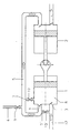
- the invention is illustrated by the example of a two-stage on the basis of the single figure Displacement pump, which is shown here as a reciprocating pump, explained in more detail become.
- Displacement pump which is shown here as a reciprocating pump, explained in more detail become.
- the conditions apply accordingly to diaphragm pumps.
- the illustration shows a two-stage positive displacement pump with two stages 1 and 2 shown.
- the inlet valve is 3 and the outlet valve designated with 4.
- the two stages are over the intermediate vacuum space 5 connected with each other.
- There is a first one for gas inlet into the intermediate vacuum space Arrangement 6 is provided, which is provided with a throttle point 9.
- a connection serves between the intermediate space 5 and the scooping space 8 Arrangement 7, which is provided with a throttle point 10.
- the gap 5 can also be connected to the suction area 12 the arrangement 7 'can be connected to the throttle point 10'.
Landscapes
- Engineering & Computer Science (AREA)
- Mechanical Engineering (AREA)
- General Engineering & Computer Science (AREA)
- Compressors, Vaccum Pumps And Other Relevant Systems (AREA)
- Reciprocating Pumps (AREA)
- Non-Positive Displacement Air Blowers (AREA)
- Structures Of Non-Positive Displacement Pumps (AREA)
- Compressor (AREA)
Claims (3)
- Dispositif de ballast de gaz pour une pompe volumétrique à plusieurs étages, dans lequel le premier étage (1) est constitué d'un ou de plusieurs étages de pompe volumétrique montés en parallèle et équipé d'une soupape d'entrée (3) et d'une soupape de sortie (4) et relié aux étages suivants par des chambres à vide intermédiaire (5), caractérisé en ce qu'un premier agencement (6) pour l'admission de gaz est réalisé de manière telle qu'il est possible de laisser.entrer du gaz dans la chambre à vide intermédiaire (5) et en ce qu'un deuxième agencement (7) est réalisé de manière telle qu'il est possible de laisser du gaz provenant de la chambre à vide intermédiaire (5) entrer dans la chambre de compression (8) du premier étage.
- Dispositif de ballast de gaz selon la revendication 1, caractérisé en ce que le deuxième agencement (7') est réalisé de manière telle qu'il est possible de laisser du gaz provenant de la chambre à vide intermédiaire (5) entrer non pas dans la chambre de compression (8) du premier étage mais dans la zone d'aspiration (12) du premier étage (1).
- Dispositif de ballast de gaz selon la revendication 1 ou 2, caractérisé en ce qu'au moins un des agencements (6, 7) ou, respectivement, des agencements (6, 7') est équipé d'un point d'étranglement (9, 10) ou, respectivement, (9, 10').
Applications Claiming Priority (2)
| Application Number | Priority Date | Filing Date | Title |
|---|---|---|---|
| DE19831123A DE19831123A1 (de) | 1998-07-11 | 1998-07-11 | Gasballasteinrichtung für mehrstufige Verdrängerpumpen |
| DE19831123 | 1998-07-11 |
Publications (3)
| Publication Number | Publication Date |
|---|---|
| EP0972938A2 EP0972938A2 (fr) | 2000-01-19 |
| EP0972938A3 EP0972938A3 (fr) | 2000-06-28 |
| EP0972938B1 true EP0972938B1 (fr) | 2004-03-03 |
Family
ID=7873738
Family Applications (1)
| Application Number | Title | Priority Date | Filing Date |
|---|---|---|---|
| EP99112217A Expired - Lifetime EP0972938B1 (fr) | 1998-07-11 | 1999-06-25 | Dispositif de ballast de gaz pour une pompe volumétrique à plusieurs étages |
Country Status (5)
| Country | Link |
|---|---|
| US (1) | US6071085A (fr) |
| EP (1) | EP0972938B1 (fr) |
| JP (1) | JP4159183B2 (fr) |
| AT (1) | ATE261063T1 (fr) |
| DE (2) | DE19831123A1 (fr) |
Families Citing this family (10)
| Publication number | Priority date | Publication date | Assignee | Title |
|---|---|---|---|---|
| GB9921983D0 (en) * | 1999-09-16 | 1999-11-17 | Boc Group Plc | Improvements in vacuum pumps |
| DE10021454C2 (de) * | 2000-05-03 | 2002-03-14 | Knf Neuberger Gmbh | Vorrichtung zum Fördern feuchter Gase |
| DE10255792C5 (de) * | 2002-11-28 | 2008-12-18 | Vacuubrand Gmbh + Co Kg | Verfahren zur Steuerung einer Vakuumpumpe sowie Vakuumpumpensystem |
| US7329105B2 (en) * | 2003-12-03 | 2008-02-12 | Haldex Brake Corporation | Multi-directional pump |
| US7399345B2 (en) * | 2006-05-09 | 2008-07-15 | Rheodyne Llc | Capillary flow restrictor apparatus |
| US20080063551A1 (en) * | 2006-09-13 | 2008-03-13 | R. Conrader Company | Head Discharging Compressor System |
| JP6150477B2 (ja) * | 2012-08-16 | 2017-06-21 | 株式会社アルバック | 往復動式ポンプ |
| KR20170054708A (ko) * | 2015-11-10 | 2017-05-18 | 엘지이노텍 주식회사 | 멀티 코일 무선 충전 방법 및 그를 위한 장치 및 시스템 |
| US11873802B2 (en) * | 2020-05-18 | 2024-01-16 | Graco Minnesota Inc. | Pump having multi-stage gas compression |
| CN112049769B (zh) * | 2020-08-11 | 2022-09-02 | 珠海格力节能环保制冷技术研究中心有限公司 | 活塞压缩机和制冷设备 |
Family Cites Families (19)
| Publication number | Priority date | Publication date | Assignee | Title |
|---|---|---|---|---|
| US272730A (en) * | 1883-02-20 | Thomas w | ||
| US688520A (en) * | 1901-10-09 | 1901-12-10 | Ebenezer Hill | Air-compressor. |
| US1724934A (en) * | 1926-12-01 | 1929-08-20 | Sulzer Ag | Compound-reciprocating compressor |
| US2205793A (en) * | 1936-08-10 | 1940-06-25 | Liquid Carbonic Corp | Compressor |
| US2812771A (en) * | 1953-08-31 | 1957-11-12 | Arthur E Mcfarland | Hydraulic testing equipment |
| DE1865607U (de) * | 1962-08-17 | 1963-01-17 | Dieteg G M B H | Vakuumpumpe, insbesondere fuer melkmaschinen. |
| US3835874A (en) * | 1967-12-22 | 1974-09-17 | F Dellasala | Method of introducing liquid doses |
| CH470589A (de) * | 1968-10-11 | 1969-03-31 | Balzers Patent Beteilig Ag | Anordnung zur Evakuierung von Rezipienten |
| FR2423656A1 (fr) * | 1978-04-19 | 1979-11-16 | Hunsinger Emile | Pompe a vide autoregulatrice |
| DE2927797A1 (de) * | 1979-07-10 | 1981-02-05 | Leybold Heraeus Gmbh & Co Kg | Verdraenger-vakuumpumpe mit saugstutzenventil |
| US4784579A (en) * | 1986-12-19 | 1988-11-15 | Allied-Signal Inc. | Hydraulic-pneumatic power transfer unit |
| DE3710782A1 (de) * | 1987-03-31 | 1988-10-20 | Vacuubrand Gmbh & Co | Verfahren und vorrichtung zum abpumpen von daempfen und/oder dampfhaltigen gemischen und/oder gas-dampf-gemischen oder dgl. medien |
| DE4136950A1 (de) * | 1991-11-11 | 1993-05-13 | Pfeiffer Vakuumtechnik | Mehrstufiges vakuumpumpsystem |
| DE4442174A1 (de) * | 1994-11-26 | 1996-05-30 | Leybold Ag | Lecksuchgerät mit Vakuumpumpen und Betriebsverfahren dazu |
| DE19524609A1 (de) * | 1995-07-06 | 1997-01-09 | Leybold Ag | Vorrichtung zum raschen Evakuieren einer Vakuumkammer |
| US5547347A (en) * | 1995-09-21 | 1996-08-20 | The Boc Group, Inc. | Gas injection apparatus and method |
| DE19634519A1 (de) * | 1996-08-27 | 1998-03-05 | Leybold Vakuum Gmbh | Kolbenvakuumpumpe mit Eintritt und Austritt |
| US5820354A (en) * | 1996-11-08 | 1998-10-13 | Robbins & Myers, Inc. | Cascaded progressing cavity pump system |
| DE19704234B4 (de) * | 1997-02-05 | 2006-05-11 | Pfeiffer Vacuum Gmbh | Verfahren und Vorrichtung zur Regelung des Saugvermögens von Vakuumpumpen |
-
1998
- 1998-07-11 DE DE19831123A patent/DE19831123A1/de not_active Withdrawn
-
1999
- 1999-06-17 JP JP17117299A patent/JP4159183B2/ja not_active Expired - Fee Related
- 1999-06-25 EP EP99112217A patent/EP0972938B1/fr not_active Expired - Lifetime
- 1999-06-25 AT AT99112217T patent/ATE261063T1/de not_active IP Right Cessation
- 1999-06-25 DE DE59908691T patent/DE59908691D1/de not_active Expired - Lifetime
- 1999-07-12 US US09/351,735 patent/US6071085A/en not_active Expired - Lifetime
Also Published As
| Publication number | Publication date |
|---|---|
| JP4159183B2 (ja) | 2008-10-01 |
| JP2000038986A (ja) | 2000-02-08 |
| EP0972938A3 (fr) | 2000-06-28 |
| DE19831123A1 (de) | 2000-01-13 |
| EP0972938A2 (fr) | 2000-01-19 |
| DE59908691D1 (de) | 2004-04-08 |
| US6071085A (en) | 2000-06-06 |
| ATE261063T1 (de) | 2004-03-15 |
Similar Documents
| Publication | Publication Date | Title |
|---|---|---|
| EP0723080B1 (fr) | Système de pompage à vide | |
| DE3710782A1 (de) | Verfahren und vorrichtung zum abpumpen von daempfen und/oder dampfhaltigen gemischen und/oder gas-dampf-gemischen oder dgl. medien | |
| EP0972938B1 (fr) | Dispositif de ballast de gaz pour une pompe volumétrique à plusieurs étages | |
| DE1628144C3 (de) | Saugdrosselsteuereinrichtung | |
| DE102006000099B4 (de) | Membranpumpe | |
| DE4331589C2 (de) | Vakuumpumpsystem | |
| WO2010075935A1 (fr) | Procédé de fonctionnement d'un moteur à combustion interne | |
| EP1434896A2 (fr) | Installation multichambre pour le traitement d'objets sous vide, procede permettant de faire le vide de cette installation et systeme utilise a cet effet | |
| EP0401399B1 (fr) | Pompe à vide élevé à deux ou plusieurs étages | |
| DE102013108090A1 (de) | Pumpenanordnung | |
| DE10018498B4 (de) | Ventilanordnung | |
| DE10255792C5 (de) | Verfahren zur Steuerung einer Vakuumpumpe sowie Vakuumpumpensystem | |
| EP0541989B1 (fr) | Système de pompe à vide multi-étage | |
| DE19919104A1 (de) | Kompressor mit veränderlicher Abgabemenge für einen Kühl- bzw. Kältemittelzyklus | |
| EP1278962B1 (fr) | Dispositif pour convoyer des gaz humides | |
| EP1131558A1 (fr) | Procede pour acheminer des gaz humides a l'aide d'un dispositif de transport et dispositif de transport approprie pour mettre ledit procede en oeuvre | |
| EP0922165B1 (fr) | Pompe a faire le vide | |
| EP1600630B1 (fr) | Compresseur à plusieurs étages et sa méthode de régulation | |
| DE2821903A1 (de) | Waelzkolbenpumpe | |
| EP3862566A1 (fr) | Pompe rotative à volume déplacé spécifique réglable et surface de compensation de pression | |
| DE19715480C2 (de) | Vakuumpumpsystem mit einer Flüssigringpumpe | |
| EP0373229A1 (fr) | Pompe à vide mécanique avec une soupape anti-retour chargée par ressort | |
| DE8816875U1 (de) | Vakuumpumpstand | |
| EP1659292B1 (fr) | Turbocompresseur | |
| DE4243793A1 (de) | Stufenschmierung für mehrstufige Vakuumpumpen |
Legal Events
| Date | Code | Title | Description |
|---|---|---|---|
| PUAI | Public reference made under article 153(3) epc to a published international application that has entered the european phase |
Free format text: ORIGINAL CODE: 0009012 |
|
| AK | Designated contracting states |
Kind code of ref document: A2 Designated state(s): AT CH DE FR GB IT LI NL |
|
| AX | Request for extension of the european patent |
Free format text: AL;LT;LV;MK;RO;SI |
|
| PUAL | Search report despatched |
Free format text: ORIGINAL CODE: 0009013 |
|
| AK | Designated contracting states |
Kind code of ref document: A3 Designated state(s): AT BE CH CY DE DK ES FI FR GB GR IE IT LI LU MC NL PT SE |
|
| AX | Request for extension of the european patent |
Free format text: AL;LT;LV;MK;RO;SI |
|
| RIC1 | Information provided on ipc code assigned before grant |
Free format text: 7F 04B 45/033 A, 7F 04B 37/14 B, 7F 04B 25/00 B, 7F 04B 37/20 B |
|
| 17P | Request for examination filed |
Effective date: 20001211 |
|
| AKX | Designation fees paid |
Free format text: AT CH DE FR GB IT LI NL |
|
| GRAP | Despatch of communication of intention to grant a patent |
Free format text: ORIGINAL CODE: EPIDOSNIGR1 |
|
| GRAS | Grant fee paid |
Free format text: ORIGINAL CODE: EPIDOSNIGR3 |
|
| GRAA | (expected) grant |
Free format text: ORIGINAL CODE: 0009210 |
|
| AK | Designated contracting states |
Kind code of ref document: B1 Designated state(s): AT CH DE FR GB IT LI NL |
|
| REG | Reference to a national code |
Ref country code: GB Ref legal event code: FG4D Free format text: NOT ENGLISH |
|
| REG | Reference to a national code |
Ref country code: CH Ref legal event code: EP |
|
| REF | Corresponds to: |
Ref document number: 59908691 Country of ref document: DE Date of ref document: 20040408 Kind code of ref document: P |
|
| GBT | Gb: translation of ep patent filed (gb section 77(6)(a)/1977) |
Effective date: 20040524 |
|
| PG25 | Lapsed in a contracting state [announced via postgrant information from national office to epo] |
Ref country code: AT Free format text: LAPSE BECAUSE OF NON-PAYMENT OF DUE FEES Effective date: 20040625 |
|
| PG25 | Lapsed in a contracting state [announced via postgrant information from national office to epo] |
Ref country code: LI Free format text: LAPSE BECAUSE OF NON-PAYMENT OF DUE FEES Effective date: 20040630 |
|
| ET | Fr: translation filed | ||
| PLBE | No opposition filed within time limit |
Free format text: ORIGINAL CODE: 0009261 |
|
| STAA | Information on the status of an ep patent application or granted ep patent |
Free format text: STATUS: NO OPPOSITION FILED WITHIN TIME LIMIT |
|
| REG | Reference to a national code |
Ref country code: CH Ref legal event code: PL |
|
| 26N | No opposition filed |
Effective date: 20041206 |
|
| REG | Reference to a national code |
Ref country code: CH Ref legal event code: NV Representative=s name: PFEIFFER VACUUM (SCHWEIZ) AG Ref country code: CH Ref legal event code: AEN Free format text: DAS PATENT IST AM 12.05.2006 GESTUETZT AUF DAS AM 20.12.2005 EINGEREICHTE WIEDEREINSETZUNGSGESUCH AUF GRUND VON ART. 47 PATG WIEDER IN KRAFT GESETZT W |
|
| PGFP | Annual fee paid to national office [announced via postgrant information from national office to epo] |
Ref country code: CH Payment date: 20080514 Year of fee payment: 10 |
|
| PGFP | Annual fee paid to national office [announced via postgrant information from national office to epo] |
Ref country code: NL Payment date: 20080610 Year of fee payment: 10 |
|
| PGFP | Annual fee paid to national office [announced via postgrant information from national office to epo] |
Ref country code: IT Payment date: 20090626 Year of fee payment: 11 |
|
| REG | Reference to a national code |
Ref country code: CH Ref legal event code: PL |
|
| NLV4 | Nl: lapsed or anulled due to non-payment of the annual fee |
Effective date: 20100101 |
|
| PG25 | Lapsed in a contracting state [announced via postgrant information from national office to epo] |
Ref country code: LI Free format text: LAPSE BECAUSE OF NON-PAYMENT OF DUE FEES Effective date: 20090630 Ref country code: CH Free format text: LAPSE BECAUSE OF NON-PAYMENT OF DUE FEES Effective date: 20090630 |
|
| PG25 | Lapsed in a contracting state [announced via postgrant information from national office to epo] |
Ref country code: NL Free format text: LAPSE BECAUSE OF NON-PAYMENT OF DUE FEES Effective date: 20100101 |
|
| PG25 | Lapsed in a contracting state [announced via postgrant information from national office to epo] |
Ref country code: IT Free format text: LAPSE BECAUSE OF NON-PAYMENT OF DUE FEES Effective date: 20100625 |
|
| PGFP | Annual fee paid to national office [announced via postgrant information from national office to epo] |
Ref country code: FR Payment date: 20120608 Year of fee payment: 14 |
|
| REG | Reference to a national code |
Ref country code: FR Ref legal event code: ST Effective date: 20140228 |
|
| PG25 | Lapsed in a contracting state [announced via postgrant information from national office to epo] |
Ref country code: FR Free format text: LAPSE BECAUSE OF NON-PAYMENT OF DUE FEES Effective date: 20130701 |
|
| PGFP | Annual fee paid to national office [announced via postgrant information from national office to epo] |
Ref country code: DE Payment date: 20150624 Year of fee payment: 17 |
|
| REG | Reference to a national code |
Ref country code: DE Ref legal event code: R119 Ref document number: 59908691 Country of ref document: DE |
|
| PG25 | Lapsed in a contracting state [announced via postgrant information from national office to epo] |
Ref country code: DE Free format text: LAPSE BECAUSE OF NON-PAYMENT OF DUE FEES Effective date: 20170103 |
|
| PGFP | Annual fee paid to national office [announced via postgrant information from national office to epo] |
Ref country code: GB Payment date: 20170517 Year of fee payment: 19 |
|
| GBPC | Gb: european patent ceased through non-payment of renewal fee |
Effective date: 20180625 |
|
| PG25 | Lapsed in a contracting state [announced via postgrant information from national office to epo] |
Ref country code: GB Free format text: LAPSE BECAUSE OF NON-PAYMENT OF DUE FEES Effective date: 20180625 |