EP0972608B1 - Dispositif d'entraínement d'une plateforme en déplacement dans un plan - Google Patents
Dispositif d'entraínement d'une plateforme en déplacement dans un plan Download PDFInfo
- Publication number
- EP0972608B1 EP0972608B1 EP98810673A EP98810673A EP0972608B1 EP 0972608 B1 EP0972608 B1 EP 0972608B1 EP 98810673 A EP98810673 A EP 98810673A EP 98810673 A EP98810673 A EP 98810673A EP 0972608 B1 EP0972608 B1 EP 0972608B1
- Authority
- EP
- European Patent Office
- Prior art keywords
- axis
- platform
- along
- carriage
- carriages
- Prior art date
- Legal status (The legal status is an assumption and is not a legal conclusion. Google has not performed a legal analysis and makes no representation as to the accuracy of the status listed.)
- Expired - Lifetime
Links
Images

Classifications
-
- F—MECHANICAL ENGINEERING; LIGHTING; HEATING; WEAPONS; BLASTING
- F16—ENGINEERING ELEMENTS AND UNITS; GENERAL MEASURES FOR PRODUCING AND MAINTAINING EFFECTIVE FUNCTIONING OF MACHINES OR INSTALLATIONS; THERMAL INSULATION IN GENERAL
- F16H—GEARING
- F16H25/00—Gearings comprising primarily only cams, cam-followers and screw-and-nut mechanisms
- F16H25/18—Gearings comprising primarily only cams, cam-followers and screw-and-nut mechanisms for conveying or interconverting oscillating or reciprocating motions
- F16H25/183—Gearings comprising primarily only cams, cam-followers and screw-and-nut mechanisms for conveying or interconverting oscillating or reciprocating motions conveying only reciprocating motion, e.g. wedges
-
- B—PERFORMING OPERATIONS; TRANSPORTING
- B23—MACHINE TOOLS; METAL-WORKING NOT OTHERWISE PROVIDED FOR
- B23Q—DETAILS, COMPONENTS, OR ACCESSORIES FOR MACHINE TOOLS, e.g. ARRANGEMENTS FOR COPYING OR CONTROLLING; MACHINE TOOLS IN GENERAL CHARACTERISED BY THE CONSTRUCTION OF PARTICULAR DETAILS OR COMPONENTS; COMBINATIONS OR ASSOCIATIONS OF METAL-WORKING MACHINES, NOT DIRECTED TO A PARTICULAR RESULT
- B23Q1/00—Members which are comprised in the general build-up of a form of machine, particularly relatively large fixed members
- B23Q1/25—Movable or adjustable work or tool supports
- B23Q1/44—Movable or adjustable work or tool supports using particular mechanisms
- B23Q1/56—Movable or adjustable work or tool supports using particular mechanisms with sliding pairs only, the sliding pairs being the first two elements of the mechanism
- B23Q1/58—Movable or adjustable work or tool supports using particular mechanisms with sliding pairs only, the sliding pairs being the first two elements of the mechanism a single sliding pair
-
- B—PERFORMING OPERATIONS; TRANSPORTING
- B23—MACHINE TOOLS; METAL-WORKING NOT OTHERWISE PROVIDED FOR
- B23Q—DETAILS, COMPONENTS, OR ACCESSORIES FOR MACHINE TOOLS, e.g. ARRANGEMENTS FOR COPYING OR CONTROLLING; MACHINE TOOLS IN GENERAL CHARACTERISED BY THE CONSTRUCTION OF PARTICULAR DETAILS OR COMPONENTS; COMBINATIONS OR ASSOCIATIONS OF METAL-WORKING MACHINES, NOT DIRECTED TO A PARTICULAR RESULT
- B23Q1/00—Members which are comprised in the general build-up of a form of machine, particularly relatively large fixed members
- B23Q1/25—Movable or adjustable work or tool supports
- B23Q1/44—Movable or adjustable work or tool supports using particular mechanisms
- B23Q1/56—Movable or adjustable work or tool supports using particular mechanisms with sliding pairs only, the sliding pairs being the first two elements of the mechanism
- B23Q1/60—Movable or adjustable work or tool supports using particular mechanisms with sliding pairs only, the sliding pairs being the first two elements of the mechanism two sliding pairs only, the sliding pairs being the first two elements of the mechanism
-
- Y—GENERAL TAGGING OF NEW TECHNOLOGICAL DEVELOPMENTS; GENERAL TAGGING OF CROSS-SECTIONAL TECHNOLOGIES SPANNING OVER SEVERAL SECTIONS OF THE IPC; TECHNICAL SUBJECTS COVERED BY FORMER USPC CROSS-REFERENCE ART COLLECTIONS [XRACs] AND DIGESTS
- Y10—TECHNICAL SUBJECTS COVERED BY FORMER USPC
- Y10T—TECHNICAL SUBJECTS COVERED BY FORMER US CLASSIFICATION
- Y10T409/00—Gear cutting, milling, or planing
- Y10T409/30—Milling
- Y10T409/309576—Machine frame
-
- Y—GENERAL TAGGING OF NEW TECHNOLOGICAL DEVELOPMENTS; GENERAL TAGGING OF CROSS-SECTIONAL TECHNOLOGIES SPANNING OVER SEVERAL SECTIONS OF THE IPC; TECHNICAL SUBJECTS COVERED BY FORMER USPC CROSS-REFERENCE ART COLLECTIONS [XRACs] AND DIGESTS
- Y10—TECHNICAL SUBJECTS COVERED BY FORMER USPC
- Y10T—TECHNICAL SUBJECTS COVERED BY FORMER US CLASSIFICATION
- Y10T74/00—Machine element or mechanism
- Y10T74/20—Control lever and linkage systems
- Y10T74/20207—Multiple controlling elements for single controlled element
- Y10T74/20341—Power elements as controlling elements
- Y10T74/20354—Planar surface with orthogonal movement only
Definitions
- the present invention relates to a device for driving a platform, suitable for carrying any object, or in the case of machine tools, a tool spindle or a workpiece spindle, in any direction of a plane, said plane containing the two axes X and Z known in the art of machine tools.
- the displacement of such a platform which can represent an element physical or in the case of machine tools, be made up directly of the workpiece spindle or tool holder, is generally obtained by two slides superimposed crossings, arranged perpendicular to each other, each of they being ordered separately according to one or the other of the directions of displacement, or being controlled simultaneously for displacement according to a combined middle management.
- a major drawback of this known device of crossed slides lies in the superposition of the two slides, making the tool spindle or workpiece carrier is relatively far from the guide rails of the slide lower on the machine frame; so we have an important torsional moment of the spindle relative to these guide slides.
- the superposition of two slides causes a lack of rigidity of the assembly between the guide rails mentioned above and the spindle.
- the backstage upper having a certain mass, is always driven when moving the lower slide, even when this upper slide is inactive, which limits the possible accelerations for a slide drive motor lower, of determined power.
- the orthogonal arrangement of the means behind the scenes of the two slides complicates the design and construction of the machine.
- JP-A-61.230.829 shows a device comprising two carriages suitable for move in one direction, one of the two carriages comprising a means of oblique guidance allowing, by a combined movement of the two carriages, a displacement of a platform in any direction.
- the second carriage, as well as the motor which drives it is completely carried by the first cart.
- a first object of the invention is to propose a displacement device of a platform in any direction of a plane containing two axes orthogonal, not meeting the drawbacks of known devices.
- a second object of the invention is that the previous device is to simple design and construction, that it is compact and rigid.
- Another object of the invention is to propose means of drive and position control of the device adapted to the geometry particular feature of this device.
- Yet another object of the invention is to propose a tool-holder spindle or workpiece holder equipped with the previous device.
- Another object of the invention is to propose a machine tool, of any type, fitted with at least one tool-holder spindle and / or minus a workpiece spindle fitted with a previous device.
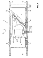
- FIGs 1 and 2 we have a portion of machine tool 1, comprising a frame 10 on which there are two guide slides 11, arranged parallel to each other along the X axis shown on the orthogonal coordinate system.
- the device according to the invention consists of a first carriage 2, a second carriage 3 and a platform 4 partially superimposed on the two carriages 2 and 3, in one or other of the ways described below.
- Platform 4 supports a spindle 5, here a tool holder spindle, but which could just as easily well be a workpiece brooch or any object.
- the two carriages 2 and 3 are able to move in both directions in direction X, being provided with slides 20, respectively 30, on the guide rails 11.
- the platform 4 is provided, on the portion of its lower face superimposed on the first carriage 2, of a slide 40 cooperating with a slide 21 arranged on the upper face of the carriage 2.
- the slide 40 is consisting in fact of two successive slides 40A and 40B arranged one after the other on the same slide 21.
- the portion of the underside of the platform 4 superimposed on the second carriage 3 is provided with a slide 41 cooperating with a slide 31 disposed on the upper face of the carriage 3, the slide 41 also consisting of two successive slides 41A and 41B arranged one after the other on the same slide 31.
- the slide 21 and the slides 40A and 40B are aligned along the axis Z, or perpendicular to the X axis, while the slide 31 and the slides 41A and 41B are aligned on an axis making an angle ⁇ with the slides of guide 11, respectively with the X axis.
- a displacement of the platform 4 is obtained, respectively from the pin 5 or the object it supports, along the X axis by moving simultaneously, at the same speed, in the same direction and in the same distance, the two carriages 2 and 3, a movement along the Z axis by blocking the first carriage 2 and by moving the second carriage 3, as well as a displacement in an intermediate direction between the X and Z axes by a combined movement at different speeds or directions of the two carriages 2 and 3.
- the angle ⁇ is preferably 45 ° in order to obtain a displacement dz corresponding to the displacement dx.
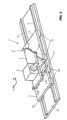
- Figure 2 which is a schematic perspective view of the device according to this first embodiment shows the position side by side of the two carriages 2 and 3 on the guide rails 11 as well as the platform 4 partially superimposed on these two carriages.
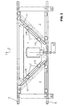
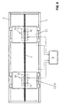
- FIG 3 we see a device similar to the previous one, except that that a carriage 3 'is mounted in place of the carriage 2 of the first form execution.
- the 3 'trolley is built and installed symmetrically to the carriage 3, relative to the axis Z and in particular comprises a slide 31 ' aligned at an angle ⁇ ', also preferably worth 45 °.
- Platform 4 differs from that of the first embodiment in that it is essentially symmetrical relative to the Z axis, comprising two slides 41A 'and 41 B' opposite the slide 31 '.
- the command is done as before by simultaneously ordering the two means drive of the two carriages, while the movement along the Z axis is controlled by a reconciliation or a relative spacing of the two carriages 3 and 3 ', the two carriages being operated at the same speed and the same value displacement dx.
- the second embodiment allows a distribution of forces between platform 4 and slides 11 which is more symmetrical, while the size of the device is larger, since the carriage 3 'is longer, in direction X, than the carriage 2.
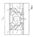
- a third embodiment of the device allows to drastically reduce the size of the trolleys 3 and 3 ' on the machine.
- the two carriages 6 and 6 ' which are symmetrical relative to the Z axis with respect to each other, include each two slides 60 and 61, respectively 60 'and 61', arranged side by side side and parallel to each other, the two slides of a carriage being inclined by an angle ⁇ or ⁇ 'relative to the X axis.
- platform 4 has slides 43A and 43B facing each other and cooperating with the slides 60 and 61, as well as slides 43A 'and 43B' cooperating with the slides 60 ' and 61 '.
- each carriage carries more than two parallel slides, the platform being fitted with corresponding slides.
- a fourth embodiment of a device according to the invention is still conceivable, said device comprising a first carriage identical to the carriage 2 of the first embodiment as well as a second carriage identical to the carriage 6 of Figure 4 of the third embodiment.
- a linear motor 7 comprising a flat armature 70 constituting the secondary of the engine, arranged parallel to the two slides guide 11, that is to say along the axis X.
- Each carriage comprises a flat inductor 71,71 'each constituting a primary of the motor, disposed under the carriage and opposite armature 70, so as to leave only a small space between the armature 70 and the inductors 71 and 71 '.
- a control unit 8 is able to order separately or simultaneously, in one direction or in the other, each inductor 71, 71 ', so as to actuate, separately or simultaneously, in one direction or the other, each carriage, thus imposing the displacements along the X and Z axes or along an intermediate axis mentioned previously to the platform as well as to the workpiece or tool holder spindle.
- the system includes a rule 80, arranged along the X axis, carrying a plurality of marks 81 placed one at a side of others.
- Each carriage includes an optical sensor 82, 82 ', arranged under the carriage opposite rule 80, a small space remaining between the ruler and sensors.
- Each sensor can therefore send a signal to the control 8, indicating the exact position of each carriage along the guide rails 11.
- Other means of position measurement, capacitive, inductive or other are also possible.
- the control unit 8 From the signals given by the sensors 82 and 82 ', making it possible to know the position of each carriage on the guide rails 11, the control unit 8 is able to calculate the coordinates X 0 , Z 0 at which the spindle is located 5, or more precisely the part or the tool which it carries, and knowing the coordinates X 1 , Y 1 to which the spindle must be brought, the control unit 8 is then able to calculate and control the necessary displacements of the carriages, taking into account the value of the angle ⁇ , and the angle ⁇ 'depending on the embodiment.
- FIG. 6 A second variant of the means of driving the two carriages is visible in figure 6.
- Each carriage comprises an electric motor or servomotor 90, 90 ′, composed of a stator 91, 91 'fixed to said carriage as well as a rotor 92, 92', drilled a longitudinal hole, said hole having a corresponding internal thread to the thread of the screw 9.
- the rotation of a rotor therefore causes a displacement of the corresponding carriage, the rotor screwing or unscrewing on the screw 9 according to the direction in which it is controlled by the control unit 8.
- the motors or servomotors can be of the stepping type.
- carriage drive can also be considered according to desired applications, for example mechanical drives, electric, pneumatic or hydraulic.
Landscapes
- Engineering & Computer Science (AREA)
- Mechanical Engineering (AREA)
- General Engineering & Computer Science (AREA)
- Machine Tool Units (AREA)
- Forklifts And Lifting Vehicles (AREA)
- Platform Screen Doors And Railroad Systems (AREA)
- Warehouses Or Storage Devices (AREA)
- Jigs For Machine Tools (AREA)
Priority Applications (6)
| Application Number | Priority Date | Filing Date | Title |
|---|---|---|---|
| DE69820426T DE69820426T2 (de) | 1998-07-14 | 1998-07-14 | Antriebseinrichtung für die Bewegung einer Plattform in einer Ebene |
| ES98810673T ES2210703T3 (es) | 1998-07-14 | 1998-07-14 | Dispositivo de accionamiento de una plataforma para desplazamiento en un plano. |
| AT98810673T ATE255978T1 (de) | 1998-07-14 | 1998-07-14 | Antriebseinrichtung für die bewegung einer plattform in einer ebene |
| EP98810673A EP0972608B1 (fr) | 1998-07-14 | 1998-07-14 | Dispositif d'entraínement d'une plateforme en déplacement dans un plan |
| US09/337,042 US6186024B1 (en) | 1998-07-14 | 1999-06-28 | Driving device for displacing a platform in a plane |
| JP19946099A JP4258790B2 (ja) | 1998-07-14 | 1999-07-13 | 一平面内でプラットホームを移動させる駆動装置 |
Applications Claiming Priority (1)
| Application Number | Priority Date | Filing Date | Title |
|---|---|---|---|
| EP98810673A EP0972608B1 (fr) | 1998-07-14 | 1998-07-14 | Dispositif d'entraínement d'une plateforme en déplacement dans un plan |
Publications (2)
| Publication Number | Publication Date |
|---|---|
| EP0972608A1 EP0972608A1 (fr) | 2000-01-19 |
| EP0972608B1 true EP0972608B1 (fr) | 2003-12-10 |
Family
ID=8236194
Family Applications (1)
| Application Number | Title | Priority Date | Filing Date |
|---|---|---|---|
| EP98810673A Expired - Lifetime EP0972608B1 (fr) | 1998-07-14 | 1998-07-14 | Dispositif d'entraínement d'une plateforme en déplacement dans un plan |
Country Status (6)
| Country | Link |
|---|---|
| US (1) | US6186024B1 (enExample) |
| EP (1) | EP0972608B1 (enExample) |
| JP (1) | JP4258790B2 (enExample) |
| AT (1) | ATE255978T1 (enExample) |
| DE (1) | DE69820426T2 (enExample) |
| ES (1) | ES2210703T3 (enExample) |
Families Citing this family (29)
| Publication number | Priority date | Publication date | Assignee | Title |
|---|---|---|---|---|
| EP1098165B1 (fr) * | 1999-11-04 | 2006-12-20 | Tesa Sa | Dispositif de déplacement et comparaison de dimensions de cales et procédé pour la comparaison de dimensions au moyen du dispositif précité |
| US6486574B2 (en) * | 2001-03-19 | 2002-11-26 | Aerotech, Inc. | Small footprint vertical lift and rotation stage |
| KR20030006756A (ko) * | 2001-07-14 | 2003-01-23 | 주식회사 져스텍 | 일렬로 배치되어 직선운동하는 두 이동부재를 이용한작업대 이동장치 |
| ITRM20010553A1 (it) * | 2001-09-12 | 2003-03-12 | New Tech Srl | Tavola portapezzo per levigatrice per incavi. |
| KR20030057995A (ko) * | 2001-12-29 | 2003-07-07 | 주식회사 져스텍 | 1축 방향 직선이동이 가능한 공작물 거치대와 평면이동 및회전운동이 가능한 공구대를 구비한 가공 장치 |
| DE10228818B4 (de) * | 2002-04-10 | 2005-08-18 | Physik Instrumente (Pi) Gmbh & Co. Kg | Positioniertisch |
| DE10348459C5 (de) * | 2003-10-14 | 2011-06-09 | Schneider Gmbh & Co. Kg | Vorrichtung und Verfahren zum spanenden Bearbeiten von Linsen |
| ITTO20050016A1 (it) * | 2005-01-13 | 2006-07-14 | Prima Ind Spa | Macchina operatrice laser |
| JP4376225B2 (ja) * | 2005-11-29 | 2009-12-02 | 日本ベアリング株式会社 | テーブル装置 |
| DE102006037624A1 (de) * | 2006-08-10 | 2008-02-14 | Urban Gmbh & Co. Maschinenbau Kg | Linearer Stelltrieb |
| US20080074020A1 (en) * | 2006-09-21 | 2008-03-27 | Doubts James L | Slidable support system for portable storage containers |
| US20080087128A1 (en) * | 2006-10-12 | 2008-04-17 | Garner Timothy D | Cross-wedge motion platform |
| USD565435S1 (en) * | 2006-11-23 | 2008-04-01 | Hiwin Mikrosystem Corp. | Precision position platform used in a linear motor and a linear module |
| JP5289898B2 (ja) * | 2008-11-07 | 2013-09-11 | 住友重機械工業株式会社 | ステージ装置及びプローバ装置 |
| KR101050455B1 (ko) | 2009-12-18 | 2011-07-19 | 이춘무 | 정밀 승강장치 |
| JP5767473B2 (ja) * | 2010-12-27 | 2015-08-19 | ヒーハイスト精工株式会社 | 位置決め部品 |
| US8683889B2 (en) * | 2012-06-14 | 2014-04-01 | Chung Yuan Christian University | Oblique-driven platform structure |
| US9073639B2 (en) * | 2013-04-03 | 2015-07-07 | Textron Innovations, Inc. | Tracking table assembly |
| EP2803443A1 (de) * | 2013-05-17 | 2014-11-19 | J. Schneeberger Maschinen Holding AG | Höhenverstellbare Vorrichtung |
| JP5541398B1 (ja) * | 2013-07-02 | 2014-07-09 | 日本精工株式会社 | テーブル装置、及び搬送装置 |
| JP5594404B1 (ja) * | 2013-07-02 | 2014-09-24 | 日本精工株式会社 | テーブル装置、搬送装置、半導体製造装置、及びフラットパネルディスプレイ製造装置 |
| US9266256B2 (en) * | 2013-09-12 | 2016-02-23 | Sino-Alloy Machinery Inc. | Cutter blade driving and positioning control structure for plastic pelletizing machine |
| TWI487593B (zh) * | 2013-12-30 | 2015-06-11 | 中原大學 | 三軸共平面斜向驅動式平台 |
| DE102015116808B3 (de) * | 2015-10-02 | 2017-01-19 | Beckhoff Automation Gmbh | Roboter, XY-Tisch für einen solchen Roboter und lineares Transportsystem |
| CH716604A1 (fr) * | 2019-09-16 | 2021-03-31 | Tornos Sa | Dispositif de positionnement d'outil, dispositif d'entrainement d'outil rotatif pour machines-outils, peigne, ainsi qu'une machine-outil. |
| EP3815853B1 (de) * | 2019-10-31 | 2024-12-25 | Osterwalder AG | Handhabungssystem |
| WO2022198587A1 (zh) * | 2021-03-25 | 2022-09-29 | 苏州迈澜医疗科技有限公司 | 六自由度运动机构 |
| CN113400036B (zh) * | 2021-07-09 | 2024-09-17 | 昆山德盛精密模具有限公司 | 一种多方向力转换快速调节机构 |
| CN115026621B (zh) * | 2022-07-26 | 2024-10-01 | 北京慧摩森电子系统技术有限公司 | 一种加工机床、三自由度自动运载装置及其控制方法 |
Family Cites Families (9)
| Publication number | Priority date | Publication date | Assignee | Title |
|---|---|---|---|---|
| US3010363A (en) * | 1958-09-25 | 1961-11-28 | Leitz Ernst Gmbh | Parallelogram guide for object tables and the like |
| US3645001A (en) * | 1970-01-28 | 1972-02-29 | Bendix Corp | Carriage and rail assembly for a high-resolution mechanical positioner |
| JPS61230829A (ja) * | 1985-04-04 | 1986-10-15 | Toshiba Mach Co Ltd | ステ−ジ装置 |
| US4838515A (en) * | 1987-05-18 | 1989-06-13 | Teledyne, Inc. | Article positioner and method |
| JPH01240246A (ja) * | 1988-03-22 | 1989-09-25 | Kazuya Hirose | テーブルの縦横移動機構 |
| US4972574A (en) * | 1988-06-08 | 1990-11-27 | Mamiya Denshi Co., Ltd. | Table driving apparatus |
| US5339749A (en) * | 1992-06-23 | 1994-08-23 | Hihasuto Seiko Co., Ltd. | Table positioning mechanism |
| DE9300510U1 (de) * | 1993-01-16 | 1993-03-11 | Döring, Martin, 4300 Essen | 3-Achs-Koordinatenfrästisch |
| US5731641A (en) * | 1996-02-28 | 1998-03-24 | Aerotech, Inc. | Linear motor driven vertical lift stage |
-
1998
- 1998-07-14 DE DE69820426T patent/DE69820426T2/de not_active Expired - Lifetime
- 1998-07-14 EP EP98810673A patent/EP0972608B1/fr not_active Expired - Lifetime
- 1998-07-14 AT AT98810673T patent/ATE255978T1/de active
- 1998-07-14 ES ES98810673T patent/ES2210703T3/es not_active Expired - Lifetime
-
1999
- 1999-06-28 US US09/337,042 patent/US6186024B1/en not_active Expired - Lifetime
- 1999-07-13 JP JP19946099A patent/JP4258790B2/ja not_active Expired - Lifetime
Also Published As
| Publication number | Publication date |
|---|---|
| ATE255978T1 (de) | 2003-12-15 |
| JP4258790B2 (ja) | 2009-04-30 |
| DE69820426D1 (de) | 2004-01-22 |
| EP0972608A1 (fr) | 2000-01-19 |
| DE69820426T2 (de) | 2004-10-07 |
| ES2210703T3 (es) | 2004-07-01 |
| JP2000079527A (ja) | 2000-03-21 |
| US6186024B1 (en) | 2001-02-13 |
Similar Documents
| Publication | Publication Date | Title |
|---|---|---|
| EP0972608B1 (fr) | Dispositif d'entraínement d'une plateforme en déplacement dans un plan | |
| EP2751636B1 (fr) | Dispositif de motorisation multiaxe et instrument de commande equipe d'un tel dispositif | |
| EP0512956B1 (fr) | Rectifieuse à commande numérique | |
| EP1666833B1 (fr) | Tête de mesure orientable motorisée | |
| FR2667478A1 (fr) | Machine-outil, notamment pour l'usinage de plaques de circuits imprimes. | |
| EP0514241B1 (fr) | Installation pour la circulation de palettes motorisées porte-pièces | |
| WO2007110406A1 (fr) | Dispositif et procede pour l'assemblage par rivetage de toles | |
| FR2488825A1 (fr) | Machine-outil avec changement rapide d'outil automatique | |
| FR2614690A1 (fr) | Appareil de lecture de contour, notamment pour monture de lunettes | |
| EP1212169A1 (fr) | Machine-outil d'usinage de type bibroche | |
| EP1321216A1 (fr) | Dispositif d'usinage de pièces à l'aide d'un faisceau laser | |
| EP0604283A1 (fr) | Dispositif de maintien et de guidage pour collimateur | |
| EP0541698A1 (fr) | Dispositif de changement de direction sur place pour chariot de manutention. | |
| CH691719A5 (fr) | Table X-Y pour déplacer une charge, telle qu'un outil, selon deux directions perpendiculaires. | |
| EP2036727B1 (fr) | Dispositif d'impression, procédé de réglage et procédé d'impression | |
| EP1672309B1 (fr) | Tête de mesure orientable motorisée | |
| FR2906490A1 (fr) | Robot industriel, notamment pour le transfert de pieces entre deux presses. | |
| EP0949047A1 (fr) | Dispositif de marquage comportant un mécanisme d'entrainement perfectionné | |
| EP0245177B1 (fr) | Dispositif de support d'une pièce d'ouvrage permettant le travail sur la cinquième face | |
| EP1522378A1 (fr) | Machine-outil à 5 axes d'usinage avec système de taillage de meule en continu | |
| EP0349438B1 (fr) | Procédé et dispositif d'identification d'outil d'écriture | |
| US4866824A (en) | Centering mechanism | |
| FR2460750A1 (fr) | Dispositif de commande d'un chariot deplacable radialement sur un plateau rotatif, notamment d'un chariot porte-outil d'une machine-outil | |
| EP4031323B1 (fr) | Peigne pour machines-outils, dispositif de positionnement d'outil, dispositif d'entrainement d'outil rotatifs ainsi qu'une machine-outil | |
| FR2464793A1 (fr) | Mecanisme d'ejection d'outil et machine equipes d'un tel mecanisme |
Legal Events
| Date | Code | Title | Description |
|---|---|---|---|
| PUAI | Public reference made under article 153(3) epc to a published international application that has entered the european phase |
Free format text: ORIGINAL CODE: 0009012 |
|
| AK | Designated contracting states |
Kind code of ref document: A1 Designated state(s): AT BE CH CY DE DK ES FR GB IT LI NL |
|
| AX | Request for extension of the european patent |
Free format text: AL;LT;LV;MK;RO;SI |
|
| 17P | Request for examination filed |
Effective date: 20000610 |
|
| AKX | Designation fees paid |
Free format text: AT BE CH CY DE DK ES LI |
|
| RBV | Designated contracting states (corrected) |
Designated state(s): AT BE CH CY DE DK ES FI FR GB GR LI |
|
| RBV | Designated contracting states (corrected) |
Designated state(s): AT BE CH CY DE DK ES FR GB IT LI NL |
|
| 17Q | First examination report despatched |
Effective date: 20010529 |
|
| GRAH | Despatch of communication of intention to grant a patent |
Free format text: ORIGINAL CODE: EPIDOS IGRA |
|
| GRAP | Despatch of communication of intention to grant a patent |
Free format text: ORIGINAL CODE: EPIDOSNIGR1 |
|
| GRAS | Grant fee paid |
Free format text: ORIGINAL CODE: EPIDOSNIGR3 |
|
| GRAA | (expected) grant |
Free format text: ORIGINAL CODE: 0009210 |
|
| AK | Designated contracting states |
Kind code of ref document: B1 Designated state(s): AT BE CH CY DE DK ES FR GB IT LI NL |
|
| PG25 | Lapsed in a contracting state [announced via postgrant information from national office to epo] |
Ref country code: CY Free format text: LAPSE BECAUSE OF FAILURE TO SUBMIT A TRANSLATION OF THE DESCRIPTION OR TO PAY THE FEE WITHIN THE PRESCRIBED TIME-LIMIT Effective date: 20031210 |
|
| REG | Reference to a national code |
Ref country code: GB Ref legal event code: FG4D Free format text: NOT ENGLISH |
|
| REG | Reference to a national code |
Ref country code: CH Ref legal event code: EP |
|
| REF | Corresponds to: |
Ref document number: 69820426 Country of ref document: DE Date of ref document: 20040122 Kind code of ref document: P |
|
| REG | Reference to a national code |
Ref country code: CH Ref legal event code: NV Representative=s name: WILLIAM BLANC & CIE CONSEILS EN PROPRIETE INDUSTRI |
|
| GBT | Gb: translation of ep patent filed (gb section 77(6)(a)/1977) |
Effective date: 20040126 |
|
| PG25 | Lapsed in a contracting state [announced via postgrant information from national office to epo] |
Ref country code: DK Free format text: LAPSE BECAUSE OF FAILURE TO SUBMIT A TRANSLATION OF THE DESCRIPTION OR TO PAY THE FEE WITHIN THE PRESCRIBED TIME-LIMIT Effective date: 20040310 |
|
| REG | Reference to a national code |
Ref country code: ES Ref legal event code: FG2A Ref document number: 2210703 Country of ref document: ES Kind code of ref document: T3 |
|
| PG25 | Lapsed in a contracting state [announced via postgrant information from national office to epo] |
Ref country code: BE Free format text: LAPSE BECAUSE OF NON-PAYMENT OF DUE FEES Effective date: 20040731 |
|
| PLBE | No opposition filed within time limit |
Free format text: ORIGINAL CODE: 0009261 |
|
| STAA | Information on the status of an ep patent application or granted ep patent |
Free format text: STATUS: NO OPPOSITION FILED WITHIN TIME LIMIT |
|
| 26N | No opposition filed |
Effective date: 20040913 |
|
| BERE | Be: lapsed |
Owner name: S.A. *KUMMER FRERES FABRIQUE DE MACHINES Effective date: 20040731 |
|
| BERE | Be: lapsed |
Owner name: S.A. *KUMMER FRERES FABRIQUE DE MACHINES Effective date: 20040731 |
|
| REG | Reference to a national code |
Ref country code: CH Ref legal event code: PFA Owner name: KUMMER FRERES SA, FABRIQUE DE MACHINES Free format text: KUMMER FRERES SA, FABRIQUE DE MACHINES#RUE DE LA PROMENADE 26#CH-2720 TRAMELAN (CH) -TRANSFER TO- KUMMER FRERES SA, FABRIQUE DE MACHINES#RUE DE LA PROMENADE 26#CH-2720 TRAMELAN (CH) |
|
| REG | Reference to a national code |
Ref country code: CH Ref legal event code: PCAR Free format text: NOVAGRAAF SWITZERLAND SA;CHEMIN DE L'ECHO 3;1213 ONEX (CH) |
|
| REG | Reference to a national code |
Ref country code: FR Ref legal event code: PLFP Year of fee payment: 19 |
|
| PGFP | Annual fee paid to national office [announced via postgrant information from national office to epo] |
Ref country code: NL Payment date: 20160722 Year of fee payment: 19 |
|
| PGFP | Annual fee paid to national office [announced via postgrant information from national office to epo] |
Ref country code: CH Payment date: 20160722 Year of fee payment: 19 Ref country code: IT Payment date: 20160725 Year of fee payment: 19 Ref country code: GB Payment date: 20160722 Year of fee payment: 19 Ref country code: DE Payment date: 20160721 Year of fee payment: 19 |
|
| PGFP | Annual fee paid to national office [announced via postgrant information from national office to epo] |
Ref country code: AT Payment date: 20160721 Year of fee payment: 19 Ref country code: FR Payment date: 20160726 Year of fee payment: 19 |
|
| PGFP | Annual fee paid to national office [announced via postgrant information from national office to epo] |
Ref country code: ES Payment date: 20160721 Year of fee payment: 19 |
|
| REG | Reference to a national code |
Ref country code: DE Ref legal event code: R119 Ref document number: 69820426 Country of ref document: DE |
|
| REG | Reference to a national code |
Ref country code: CH Ref legal event code: PL |
|
| REG | Reference to a national code |
Ref country code: NL Ref legal event code: MM Effective date: 20170801 |
|
| REG | Reference to a national code |
Ref country code: AT Ref legal event code: MM01 Ref document number: 255978 Country of ref document: AT Kind code of ref document: T Effective date: 20170714 |
|
| GBPC | Gb: european patent ceased through non-payment of renewal fee |
Effective date: 20170714 |
|
| REG | Reference to a national code |
Ref country code: FR Ref legal event code: ST Effective date: 20180330 |
|
| PG25 | Lapsed in a contracting state [announced via postgrant information from national office to epo] |
Ref country code: LI Free format text: LAPSE BECAUSE OF NON-PAYMENT OF DUE FEES Effective date: 20170731 Ref country code: NL Free format text: LAPSE BECAUSE OF NON-PAYMENT OF DUE FEES Effective date: 20170801 Ref country code: DE Free format text: LAPSE BECAUSE OF NON-PAYMENT OF DUE FEES Effective date: 20180201 Ref country code: CH Free format text: LAPSE BECAUSE OF NON-PAYMENT OF DUE FEES Effective date: 20170731 Ref country code: GB Free format text: LAPSE BECAUSE OF NON-PAYMENT OF DUE FEES Effective date: 20170714 |
|
| PG25 | Lapsed in a contracting state [announced via postgrant information from national office to epo] |
Ref country code: FR Free format text: LAPSE BECAUSE OF NON-PAYMENT OF DUE FEES Effective date: 20170731 Ref country code: AT Free format text: LAPSE BECAUSE OF NON-PAYMENT OF DUE FEES Effective date: 20170714 |
|
| PG25 | Lapsed in a contracting state [announced via postgrant information from national office to epo] |
Ref country code: IT Free format text: LAPSE BECAUSE OF NON-PAYMENT OF DUE FEES Effective date: 20170714 |
|
| REG | Reference to a national code |
Ref country code: ES Ref legal event code: FD2A Effective date: 20181029 |
|
| PG25 | Lapsed in a contracting state [announced via postgrant information from national office to epo] |
Ref country code: ES Free format text: LAPSE BECAUSE OF NON-PAYMENT OF DUE FEES Effective date: 20170715 |